RU2663503C2 - Grinding machine and method of grinding axial drilling and bilateral treatment flat external surface products - Google Patents
Grinding machine and method of grinding axial drilling and bilateral treatment flat external surface products Download PDFInfo
- Publication number
- RU2663503C2 RU2663503C2 RU2016137818A RU2016137818A RU2663503C2 RU 2663503 C2 RU2663503 C2 RU 2663503C2 RU 2016137818 A RU2016137818 A RU 2016137818A RU 2016137818 A RU2016137818 A RU 2016137818A RU 2663503 C2 RU2663503 C2 RU 2663503C2
- Authority
- RU
- Russia
- Prior art keywords
- grinding
- product
- headstock
- drilling
- clamping
- Prior art date
Links
- 238000000227 grinding Methods 0.000 title claims abstract description 462
- 238000005553 drilling Methods 0.000 title claims abstract description 76
- 238000000034 method Methods 0.000 title claims description 57
- 230000002146 bilateral effect Effects 0.000 title 1
- 238000012545 processing Methods 0.000 claims abstract description 41
- 239000002173 cutting fluid Substances 0.000 claims description 9
- 230000020347 spindle assembly Effects 0.000 claims description 7
- 239000010432 diamond Substances 0.000 claims description 3
- 229910003460 diamond Inorganic materials 0.000 claims description 3
- 238000005520 cutting process Methods 0.000 claims description 2
- 238000004519 manufacturing process Methods 0.000 abstract description 12
- 239000000126 substance Substances 0.000 abstract 1
- 239000000047 product Substances 0.000 description 196
- 238000000576 coating method Methods 0.000 description 13
- 239000011248 coating agent Substances 0.000 description 11
- 230000008901 benefit Effects 0.000 description 9
- PZNSFCLAULLKQX-UHFFFAOYSA-N Boron nitride Chemical compound N#B PZNSFCLAULLKQX-UHFFFAOYSA-N 0.000 description 7
- 239000000919 ceramic Substances 0.000 description 5
- 238000007514 turning Methods 0.000 description 4
- 230000005540 biological transmission Effects 0.000 description 3
- 238000004590 computer program Methods 0.000 description 3
- 238000009826 distribution Methods 0.000 description 3
- 239000012809 cooling fluid Substances 0.000 description 2
- 239000000110 cooling liquid Substances 0.000 description 2
- 238000013461 design Methods 0.000 description 2
- 230000007613 environmental effect Effects 0.000 description 2
- 239000012530 fluid Substances 0.000 description 2
- 238000003754 machining Methods 0.000 description 2
- 238000005457 optimization Methods 0.000 description 2
- 230000015572 biosynthetic process Effects 0.000 description 1
- 238000005266 casting Methods 0.000 description 1
- 239000002826 coolant Substances 0.000 description 1
- 239000010431 corundum Substances 0.000 description 1
- 229910052593 corundum Inorganic materials 0.000 description 1
- 230000001419 dependent effect Effects 0.000 description 1
- 230000009977 dual effect Effects 0.000 description 1
- 238000005516 engineering process Methods 0.000 description 1
- 239000012467 final product Substances 0.000 description 1
- -1 for example Substances 0.000 description 1
- 239000012634 fragment Substances 0.000 description 1
- 238000003780 insertion Methods 0.000 description 1
- 230000037431 insertion Effects 0.000 description 1
- 238000009434 installation Methods 0.000 description 1
- 230000002452 interceptive effect Effects 0.000 description 1
- 230000001050 lubricating effect Effects 0.000 description 1
- 239000000463 material Substances 0.000 description 1
- 238000005259 measurement Methods 0.000 description 1
- 238000012986 modification Methods 0.000 description 1
- 230000004048 modification Effects 0.000 description 1
- 238000002203 pretreatment Methods 0.000 description 1
- 238000012546 transfer Methods 0.000 description 1
Images

Classifications
-
- B—PERFORMING OPERATIONS; TRANSPORTING
- B24—GRINDING; POLISHING
- B24B—MACHINES, DEVICES, OR PROCESSES FOR GRINDING OR POLISHING; DRESSING OR CONDITIONING OF ABRADING SURFACES; FEEDING OF GRINDING, POLISHING, OR LAPPING AGENTS
- B24B5/00—Machines or devices designed for grinding surfaces of revolution on work, including those which also grind adjacent plane surfaces; Accessories therefor
- B24B5/01—Machines or devices designed for grinding surfaces of revolution on work, including those which also grind adjacent plane surfaces; Accessories therefor for combined grinding of surfaces of revolution and of adjacent plane surfaces on work
-
- B—PERFORMING OPERATIONS; TRANSPORTING
- B24—GRINDING; POLISHING
- B24B—MACHINES, DEVICES, OR PROCESSES FOR GRINDING OR POLISHING; DRESSING OR CONDITIONING OF ABRADING SURFACES; FEEDING OF GRINDING, POLISHING, OR LAPPING AGENTS
- B24B27/00—Other grinding machines or devices
-
- B—PERFORMING OPERATIONS; TRANSPORTING
- B24—GRINDING; POLISHING
- B24B—MACHINES, DEVICES, OR PROCESSES FOR GRINDING OR POLISHING; DRESSING OR CONDITIONING OF ABRADING SURFACES; FEEDING OF GRINDING, POLISHING, OR LAPPING AGENTS
- B24B27/00—Other grinding machines or devices
- B24B27/0061—Other grinding machines or devices having several tools on a revolving tools box
-
- B—PERFORMING OPERATIONS; TRANSPORTING
- B24—GRINDING; POLISHING
- B24B—MACHINES, DEVICES, OR PROCESSES FOR GRINDING OR POLISHING; DRESSING OR CONDITIONING OF ABRADING SURFACES; FEEDING OF GRINDING, POLISHING, OR LAPPING AGENTS
- B24B41/00—Component parts such as frames, beds, carriages, headstocks
- B24B41/06—Work supports, e.g. adjustable steadies
- B24B41/067—Work supports, e.g. adjustable steadies radially supporting workpieces
-
- B—PERFORMING OPERATIONS; TRANSPORTING
- B24—GRINDING; POLISHING
- B24B—MACHINES, DEVICES, OR PROCESSES FOR GRINDING OR POLISHING; DRESSING OR CONDITIONING OF ABRADING SURFACES; FEEDING OF GRINDING, POLISHING, OR LAPPING AGENTS
- B24B5/00—Machines or devices designed for grinding surfaces of revolution on work, including those which also grind adjacent plane surfaces; Accessories therefor
- B24B5/02—Machines or devices designed for grinding surfaces of revolution on work, including those which also grind adjacent plane surfaces; Accessories therefor involving centres or chucks for holding work
- B24B5/04—Machines or devices designed for grinding surfaces of revolution on work, including those which also grind adjacent plane surfaces; Accessories therefor involving centres or chucks for holding work for grinding cylindrical surfaces externally
-
- B—PERFORMING OPERATIONS; TRANSPORTING
- B24—GRINDING; POLISHING
- B24B—MACHINES, DEVICES, OR PROCESSES FOR GRINDING OR POLISHING; DRESSING OR CONDITIONING OF ABRADING SURFACES; FEEDING OF GRINDING, POLISHING, OR LAPPING AGENTS
- B24B5/00—Machines or devices designed for grinding surfaces of revolution on work, including those which also grind adjacent plane surfaces; Accessories therefor
- B24B5/02—Machines or devices designed for grinding surfaces of revolution on work, including those which also grind adjacent plane surfaces; Accessories therefor involving centres or chucks for holding work
- B24B5/06—Machines or devices designed for grinding surfaces of revolution on work, including those which also grind adjacent plane surfaces; Accessories therefor involving centres or chucks for holding work for grinding cylindrical surfaces internally
Landscapes
- Engineering & Computer Science (AREA)
- Mechanical Engineering (AREA)
- Grinding Of Cylindrical And Plane Surfaces (AREA)
- Constituent Portions Of Griding Lathes, Driving, Sensing And Control (AREA)
- Grinding-Machine Dressing And Accessory Apparatuses (AREA)
- Finish Polishing, Edge Sharpening, And Grinding By Specific Grinding Devices (AREA)
Abstract
Description
Шлифовальные станки и способы для такого шлифования, в частности, деталей шестерен для приводов или фланцевых деталей, известны, причем на этих известных шлифовальных станках и известными способами на одном шлифовальном станке осуществляют, в частности, несколько операций или отдельных операций; и напротив, полная обработка таких изделий на одном и том же шлифовальном станке не известна.Grinding machines and methods for such grinding, in particular gear parts for drives or flange parts, are known, moreover, on these known grinding machines and known methods, several operations or separate operations are carried out on a single grinding machine; conversely, the complete processing of such products on the same grinding machine is not known.
Из DE 10 2012 012 331 A1 известны токарные станки и шлифовальные станки, с помощью которых проводят наружную круглую и чистовую обработку торцевых поверхностей изделий.From DE 10 2012 012 331 A1, lathes and grinding machines are known by which an external round and finish machining of the end surfaces of products is carried out.
В известном токарном станке приводится описание двух расположенных напротив инструментальных шпинделей, несущих несколько различных инструментов и осуществляющих внешнюю обработку изделий. Изделие фиксируют первым шпинделем изделия в положении, в каком можно осуществлять внешнюю обработку и расположенного напротив места зажима концевого участка изделия. Изделие передают от этого первого шпинделя изделия расположенному напротив второму шпинделю изделия, так называемому противошпинделю, поэтому можно обрабатывать также вторую, закрепленную сначала торцевую сторону изделия. Если закрепление в противошпинделе не допускает обработку на участке торцевой стороны, обрабатываемое изделие можно фиксировать по центру посредством конического конца задней бабки, установленного в одном из приспособлений для крепления инструмента или инструментальных шпинделей. Однако, в этом случае сохраняется закрепление посредством первого инструментального шпинделя.A well-known lathe describes two opposite tool spindles that carry several different tools and carry out external processing of products. The product is fixed with the first spindle of the product in a position in which external processing can be performed and located opposite the clamping point of the end portion of the product. The product is transferred from this first product spindle opposite to the second product spindle, the so-called counter spindle, therefore, it is also possible to process the second end face of the product fixed first. If the fastening in the counter spindle does not allow processing on the end-face section, the workpiece can be fixed in the center by means of the conical end of the tailstock installed in one of the fixtures for fastening the tool or tool spindles. However, in this case, fixing is maintained by the first tool spindle.
В описанном шлифовальном станке напротив передней бабки изделия расположена отдельная задняя бабка. Шлифовальная бабка может осуществлять шлифовальным кругом наружную круглую внешнюю обработку, а с помощью своих торцевых сторон при необходимости обрабатывать также и плоские стороны на фланцах изделия, однако, не непосредственно на конце, фиксированном посредством задней бабки. Второй инструментальный шпиндель расположен относительно шлифовальной бабки напротив и выполнен в виде многофункционального устройства. Это многофункциональное устройство несет, например, люнет и измерительные датчики для проведения измерений процесса. Кроме того, многофункциональное устройство несет узел правки, позволяющий править шлифовальный круг, расположенный на находящейся напротив шлифовальной бабке. Задняя бабка и шлифовальная бабка выполнены в публикации как отдельные устройства. Установленный в задней бабке конический конец задней бабки служит только для центрирования в случае, если ранее в изделии был выполнен так называемый центр. Устройство для внутреннего шлифования, как для токарного станка, так и для шлифовального станка не описано.In the described grinding machine opposite the front headstock of the product is a separate tailstock. The grinding head can carry out an external circular external machining with a grinding wheel, and with its end sides, if necessary, also process the flat sides on the product flanges, however, not directly at the end fixed by the tailstock. The second tool spindle is located relative to the grinding headstock and is made in the form of a multifunctional device. This multifunctional device carries, for example, a backrest and measuring sensors for carrying out process measurements. In addition, the multifunctional device carries a dressing unit, allowing you to edit the grinding wheel located on the opposite headstock. The tailstock and grinding headstock are made in the publication as separate devices. The conical end of the tailstock installed in the tailstock serves only for centering if the so-called center has been previously made in the product. A device for internal grinding for both a lathe and a grinding machine is not described.
В DE 10 2005 018 959 B3 описан способ и шлифовальный инструмент для внутреннего круглого шлифования и торцового шлифования изделия в виде шестерни. В этой публикации осуществляется внутреннее шлифование сверления и следующее за ним торцовое шлифование, по меньшей мере, одной торцевой поверхности на одной стороне шестерни с помощью одного и того же шлифовального круга, профилированного так, что предусмотрены два разных конических участка для соответствующих задач шлифования. Передний конический участок шлифует внутреннее сверление шестерни, тогда, как выполненный с уступом за коническим участком в виде буртика участок шлифования используют для внешней плоской стороны шестерни. Для этого шлифовальные шпиндели устанавливают соответственно углу конуса настолько косо, что поверхности внутреннего сверления шлифуют соосно к центральной оси шестерни. В соответствии с углом конуса второго участка шлифования для торцевых поверхностей для профилированного шлифовального круга выбирают такой угол наклона, при котором торцевую поверхность можно шлифовать вертикально к центральной оси шестерни. Посредством такого профилированного шлифовального круга можно шлифовать внутреннюю поверхность сверления и торцевую поверхность на одной внешней стороне шестерни только поочередно. Условия закрепления и устройства для шлифования расположенной также напротив шлифуемой плоской стороны противоположной плоской стороны шестерни не описаны.DE 10 2005 018 959 B3 describes a method and a grinding tool for internal circular grinding and face grinding of a gear product. This publication carries out internal grinding of the drilling and subsequent mechanical grinding of at least one end surface on one side of the gear using the same grinding wheel, profiled so that two different conical sections are provided for the respective grinding tasks. The front conical section grinds the internal drilling of the gear, while the grinding section made with a step behind the conical section in the form of a shoulder is used for the outer flat side of the gear. To do this, the grinding spindles are set according to the angle of the cone so obliquely that the internal drilling surfaces are ground coaxially to the central axis of the gear. In accordance with the cone angle of the second grinding section for the end surfaces, a tilt angle is selected for the shaped grinding wheel at which the end surface can be ground vertically to the central axis of the gear. By means of such a profiled grinding wheel, it is possible to grind the inner surface of the drilling and the end surface on one outer side of the gear only alternately. The fixing conditions and the device for grinding also located opposite the grinding flat side of the opposite flat side of the gear are not described.
В DE 197 53 797 C2 описано устройство для шлифования изделий с устройством для крепления изделия и, по меньшей мере, с одним шлифовальным инструментом. Изделие может быть также шестерней, в которой также осуществляется обработка ее конечных поверхностей. Изделие закрепляют в зажимном устройстве приспособления для крепления инструмента, и осуществляют по очереди технологические процессы для его внутреннего диаметра, а также для внешних профилей, т.е. плоских сторон. После чистового шлифования находящихся на одной стороне шестерни плоских сторон, а также внутреннего диаметра изделие выгружают из станка посредством передаточного устройства. Шлифование также и противоположной плоской стороны в описании этого известного станка не приводится.DE 197 53 797 C2 describes a device for grinding products with a device for securing the product and at least one grinding tool. The product may also be a gear, in which the processing of its final surfaces is also carried out. The product is fixed in the clamping device for tool attachment, and technological processes are carried out in turn for its internal diameter, as well as for external profiles, i.e. flat sides. After fine grinding of the flat sides located on one side of the gear, as well as the inner diameter, the product is unloaded from the machine by means of a transmission device. Grinding also the opposite flat side in the description of this known machine is not given.
Кроме того, из DE 36 28 977 A1 известен шлифовальный станок для внутреннего круглого шлифования, торцового круглого шлифования и внешнего круглого шлифования. В этом известном шлифовальном станке предусмотрена передняя бабка изделия с зажимным патроном для шлифуемого изделия в качестве единственного зажимного устройства.In addition, from DE 36 28 977 A1, a grinding machine for internal circular grinding, face circular grinding and external circular grinding is known. In this known grinding machine, a headstock of a product with a chuck for a grinding product as a sole clamping device is provided.
Шлифование сверлений, внешних круглых поверхностей и плоских внешних поверхностей осуществляют соответствующими шлифовальными кругами, с возможностью управления ими компьютерным числовым программным управлением на отдельных шлифовальных бабках для введения в контакт для шлифования. Шлифование плоских сторон и противоположных плоских сторон на одном и том же изделии не описано. Положительным результатом компоновки двух независимых шлифовальных бабок является возможность одновременного шлифования, как внешних профилей, так и внутреннего сверления.Grinding of drillings, external round surfaces and flat external surfaces is carried out by appropriate grinding wheels, with the possibility of controlling them by computer numerical program control on individual grinding headstock for introduction into contact for grinding. Grinding flat sides and opposite flat sides on the same product is not described. A positive result of the arrangement of two independent grinding heads is the possibility of simultaneous grinding of both external profiles and internal drilling.
Общим для известных шлифовальных станков и способов изготовления соответствующих изделий на этих шлифовальных станках является то, что шлифуемые изделия нельзя полностью обрабатывать на одном станке.Common to known grinding machines and methods for manufacturing the corresponding products on these grinding machines is that the grinding products cannot be completely processed on one machine.
Так как полная обработка шлифованием выше описанных изделий на одном и том же шлифовальном станке в известных шлифовальных станках не возможна, требуется предоставлять другие станки или, по меньшей мере, соответствующие другие технологические позиции для шлифования для полной обработки таких изделий. Недостатком такого решения является необходимость последовательность операций и изделия должны направляться для этого в другой станок или на другую позицию. Для этого необходимы дополнительные транспортировочные устройства. Кроме того, вследствие этого возникает недостаток, заключающийся в том, что изделия до погрузки во второй станок или во вторую позицию снова подвергаются влиянию других температур окружающей среды, а вместе с этим измененным условиям внешней среды и имеют также в каждом случае разное расширение вследствие разных температурных условий окружающей среды, что может непосредственное сказываться на последующей точности изготовления.Since complete processing by grinding the above-described products on the same grinding machine in known grinding machines is not possible, it is necessary to provide other machines or at least corresponding other processing positions for grinding for complete processing of such products. The disadvantage of this solution is the need for a sequence of operations and products must be sent for this to another machine or to another position. This requires additional transportation devices. In addition, as a result of this, a disadvantage arises in that the products are again exposed to other ambient temperatures before being loaded into the second machine or into the second position, and with this altered environmental conditions, they also have different expansion in each case due to different temperature environmental conditions, which may directly affect subsequent manufacturing accuracy.
Кроме того, в DE 195 13 963 A1 описан токарный станок с числовым программным управлением, посредством которого изделия можно одновременно обрабатывать внутри и снаружи в шпинделе изделия и в противошпинделе. Обрабатываемое изделие закрепляют в так называемом шпинделе изделия, а также в противошпинделе и его можно обрабатывать соответственно одним сверлильным инструментом с внутренним сверлением, причем его одновременно можно шлифовать также снаружи посредством инструментов, расположенных на несущем элементе инструмента. Во время всей обработки изделие остается в одном и том же зажиме в соответствующем зажимном патроне, а поэтому не может обрабатываться на участке зажима.In addition, DE 195 13 963 A1 describes a numerically controlled lathe by which products can be machined simultaneously inside and out in the product spindle and in the counter spindle. The workpiece is fixed in the so-called spindle of the product, as well as in the counter spindle and it can be machined with one drilling tool with internal drilling, respectively, and at the same time it can also be grinded from the outside using tools located on the tool carrier. During the entire processing, the product remains in the same clamp in the corresponding clamping chuck, and therefore cannot be processed in the clamping area.
В DE 603 03 672 T2 описан станок, посредством которого у инструмента могут обрабатываться цилиндрические и торцовые внешние поверхности, а также сверления. Для этого предусмотрен ряд инструментальных шпинделей и бабка изделия, поэтому над изделием можно выполнять различные работы. Полная обработка также не возможна, так как изделие во время выполняемых многочисленных технологических процессов остается закрепленным в бабке изделия в зажимном патроне.DE 603 03 672 T2 describes a machine through which cylindrical and end external surfaces, as well as drilling, can be machined on a tool. For this, a number of tool spindles and a headstock of the product are provided, therefore, various work can be performed on the product. Full processing is also not possible, since the product remains attached to the headstock in the chuck during numerous technological processes.
В DE 3817 161 A1 приводится описание круглошлифовального станка с числовым программным управлением для шлифования изделий в виде патрона и заостренных изделий. Посредством этого известного круглошлифовального станка можно выполнять внутреннее шлифование, круглое шлифование, торцовое шлифование между коническими концами и с коническими концами и патроном. При обработке так называемых изделий в виде патрона обрабатываемое изделие остается закрепленным в зажимном патроне. Правда, при шлифовании так называемых заостренных изделий внешние поверхности изделия можно обрабатывать, в частности, по существу полностью, хотя обработка сверлений при таком закреплении исключена.DE 3817 161 A1 describes a numerically controlled circular grinding machine for grinding articles in the form of a chuck and pointed articles. By means of this known circular grinding machine, it is possible to perform internal grinding, circular grinding, face grinding between conical ends and with conical ends and chuck. When processing the so-called products in the form of a cartridge, the workpiece remains fixed in the chuck. However, when grinding the so-called pointed products, the external surfaces of the product can be processed, in particular, essentially completely, although drilling processing with such a fastening is excluded.
Недостатком известных решений шлифования также является то, что возникают большие трудности для планирования процессов и требуются более высокая трудоемкость для контроля работы соответствующих этапов обработки. Это приводит к более высоким издержкам, так как при необходимости необходимо наличие, например, вдвое большего количества измерительных инструментов.A disadvantage of the known grinding solutions is also that there are great difficulties for the planning of processes and a higher complexity is required to control the operation of the respective processing steps. This leads to higher costs, since if necessary it is necessary to have, for example, twice as many measuring instruments.
В общем, следует констатировать, что имеющиеся в известных шлифовальных станках или в осуществляемых на них способах недостатки приводят к тому, что изделия, с одной стороны, подвержены определенным ограничениям в отношении высокой точности изготовления, а, с другой стороны, более трудоемкие в изготовлении, а вследствие этого их изготавливают с более высокими производственными издержками.In general, it should be noted that the shortcomings existing in known grinding machines or in the methods carried out on them lead to the fact that the products, on the one hand, are subject to certain restrictions with respect to high precision manufacturing, and, on the other hand, are more time-consuming to manufacture, and as a result, they are made with higher production costs.
В противоположность этому задача предложенного изобретения - предоставить шлифовальный станок согласно пункту 1 ограничительной части формулы изобретения и осуществляемый на нем способ, с помощью которых возможно высокоточное и экономичное полное шлифование изделий с центральным сверлением и имеющих с двух сторон плоские и/или неплоские внешние поверхности, в частности, шестерен для привода, на одном единственном шлифовальном станке.In contrast, the objective of the proposed invention is to provide a grinding machine according to paragraph 1 of the restrictive part of the claims and the method carried out therein, with the help of which high-precision and economical complete grinding of products with central drilling and having flat and / or non-planar external surfaces on both sides is possible, particular gears for the drive, on one single grinding machine.
Эта задача решена посредством шлифовального станка, охарактеризованного признаками пункта 1 формулы изобретения, а также посредством способа, охарактеризованного признаками пункта 11 формулы изобретения. Целесообразные усовершенствованные варианты изобретения определены в соответствующих зависимых пунктах формулы изобретения.This problem is solved by means of a grinding machine, characterized by the features of paragraph 1 of the claims, as well as by a method, characterized by the characteristics of
Согласно изобретению с помощью предлагаемого шлифовального станка осуществляют полную обработку изделий, имеющих центральное сверление, а также плоские и неплоские внешние поверхности на обеих торцевых сторонах изделия, например, фланцевых валов или шестерен для привода. Согласно изобретению, шлифовальный станок имеет первую шлифовальную бабку, на которой расположен внешний шлифовальный круг для обработки соответствующих внешних поверхностей изделия, вторую шлифовальную бабку, несущую внутренний шлифовальный круг для обработки внутренней поверхности сверления и бабку изделия для крепления изделия. Шлифуемое изделие закрепляют в зажимном патроне бабки изделия, поэтому изделие можно шлифовать на не закрытых зажимным патроном внешних поверхностях и во внутренних поверхностях сверления. В частности, можно шлифовать, как плоские, так и неплоские внешние поверхности, обращенные в направлении ко второй шлифовальной бабке и сверление. Изделие закреплено в бабке изделия так, что оно фиксировано в отношении своего пространственного расположения на центральной оси зажимного патрона в первом положении зажима. Согласно изобретению, во второй или на второй шлифовальной бабке расположено зажимное устройство, в частности, вторая шлифовальная бабка несет такое зажимное устройство. Зажимное устройство неподвижно соединено со второй шлифовальной бабкой, хотя и с возможностью отдельного управляемого перемещения к шлифовальной бабке относительно, по меньшей мере, одной оси компьютерного программного управления. Для согласно изобретению шлифовального станка инструментом для обработки является внутренний шлифовальный круг, который несет шлифовальная бабка, а согласно изобретению инструмент для обработки и зажимное устройство соединены друг с другом в неподвижный узел в качестве комбинированного узла.According to the invention, with the use of the proposed grinding machine, complete processing of products having central drilling, as well as flat and non-planar external surfaces on both end faces of the product, for example, flange shafts or gears for the drive, is carried out. According to the invention, the grinding machine has a first grinding head on which an external grinding wheel is located for processing the respective external surfaces of the product, a second grinding head supporting an internal grinding wheel for processing the inner drilling surface and a headstock for securing the product. The grinded product is fixed in the chuck of the headstock of the product, therefore, the product can be grinded on the external surfaces not closed by the chuck and in the internal drilling surfaces. In particular, it is possible to grind both flat and non-planar external surfaces facing towards the second grinding head and drilling. The product is fixed in the headstock of the product so that it is fixed in relation to its spatial location on the Central axis of the chuck in the first position of the clamp. According to the invention, a clamping device is located in the second or second grinding headstock, in particular, the second grinding head carries such a clamping device. The clamping device is fixedly connected to the second grinding headstock, although with the possibility of a separate controlled movement to the grinding headstock relative to at least one axis of the computer program control. For, according to the invention of the grinding machine, the processing tool is an internal grinding wheel carried by the grinding head, and according to the invention, the processing tool and the clamping device are connected to each other in a fixed unit as a combined unit.
В принципе, сначала может показаться невыгодной установка дополнительного зажимного устройства в шлифовальной бабке, так как шлифовальная бабка сама по себе является довольно сложным и дорогостоящим конструктивным элементом или в отношении затрат - дорогим конструктивным узлом, без возможности использования его для выполнения своей настоящей задачи по шлифованию именно тогда, когда зажимное устройство действует. В частности, при желании достижения небольшой продолжительности тактов, требуется предусматривать, по меньшей мере, две шлифовальные бабки для возможности проведения определенных шлифуемых участков, по меньшей мере, периодически параллельно по времени. Для высокой точности, требующейся в настоящее при шлифовании и которую нужно достигать, шлифовальные бабки изготавливают соответственно сложными и высокопрочными. Неожиданно оказалось, что эту высокую прочность, как таковую, можно использовать с пользой для зажимного устройства, без необходимости предусматривать второе, также имеющее высокую прочность зажимное устройство. Зажимное устройство, так сказать, выигрывает за счет внутренней прочности и жесткости шлифовальной бабки. Вследствие этого в комбинации с инструментом и зажимным устройством также возникает работающий с высокой точностью конструктивный узел, посредством которого повышается, кроме того, точность изготовления сложных изделий и возникает также возможность их полной обработки на одном единственном станке, что касается их центрального сверления, а также плоских и неплоских внешних поверхностей на обеих сторонах.In principle, at first it may seem disadvantageous to install an additional clamping device in the grinding head, since the grinding head itself is a rather complex and expensive structural element or, in terms of cost, an expensive structural unit, without the possibility of using it to perform its real grinding task when the clamping device operates. In particular, if you want to achieve a short cycle time, you must provide at least two grinding headstock for the possibility of certain grinding areas, at least periodically in parallel in time. For the high precision currently required during grinding and which must be achieved, the grinding headstock is made respectively complex and high-strength. It has unexpectedly turned out that this high strength, as such, can be used to advantage for a clamping device, without having to provide a second, also having a high strength clamping device. The clamping device, so to speak, benefits from the internal strength and rigidity of the grinding head. As a result of this, in combination with a tool and a clamping device, a structural unit operating with high precision also appears, by means of which, moreover, the accuracy of manufacturing complex products is increased and there is also the possibility of their complete processing on a single machine, as for their central drilling, as well as flat and non-planar exterior surfaces on both sides.
Вторая, несущая зажимное устройство шлифовальная бабка может перемещаться относительно центральной оси этого зажимного устройства так, что зажимное устройство может входить в уже отшлифованное сверление изделия, а изделие может закрепляться с помощью его во втором положении зажима. В этом втором положении зажима на одной прямой друг с другом располагается центральная ось зажимного устройства и центральная ось зажимного патрона, причем оба положения зажима существуют, по меньшей мере, периодически равномерно. После разъединения из первого положения зажима и, когда второе положение зажима является единственным закреплением, шлифуют посредством внешнего шлифовального круга вторую плоскую и/или неплоскую внешнюю поверхность, обращенную по направлению к бабке изделия. В то время, как первая и второе положение зажима выполнены так, что их центральные оси располагаются на одной прямой друг с другом, а после разъединения первого положения зажима с высокой точностью сохраняется пространственное позиционирование шлифуемого изделия, можно достигать высокой точности шлифования, в частности, для первой плоской стороны и противоположной плоской стороны, под которой понимают вторую плоскую внешнюю поверхность, обращенную к бабке изделия.The second grinding head supporting the clamping device can move relative to the central axis of this clamping device so that the clamping device can enter into the already polished drilling of the product, and the product can be fixed with it in the second clamping position. In this second clamping position, the central axis of the clamping device and the central axis of the chuck are located on one straight line with each other, both clamping positions exist at least periodically uniformly . After disconnecting from the first position of the clamp and when the second position of the clamp is the only fastening, the second flat and / or non-planar outer surface, facing the head of the product, is ground using an external grinding wheel. While the first and second position of the clamp are made so that their central axes are located on one straight line with each other, and after the first position of the clamp is disconnected, the spatial positioning of the grinding product is maintained with high accuracy, high grinding accuracy can be achieved, in particular, for the first flat side and the opposite flat side, by which we mean the second flat outer surface facing the headstock of the product.
Предпочтительно, если зажимное устройство является зажимной оправкой, с возможностью ее перемещения в осевом направлении посредством компьютерного числового программного управления и, в частности, приведения во вращение. Предполагаются, однако, технические варианты выполнения, в которых зажимная оправка не должна перемещаться вдоль своей продольной оси, а только приводится во вращательное движение. Возможность осевого перемещения, осуществляемая тогда либо в зажимной оправке, либо второй шлифовальной бабке посредством оси Z2 служит для такого введения зажимной оправки в центральное сверление изделия для оптимальных условий закрепления, при котором она надежно закреплена и без образования закреплений под углом и так, чтобы сохранялась выполненная в шпинделе изделия посредством его зажимного устройства центральная ось после передачи в зажимную оправку для изделия.Preferably, if the clamping device is a clamping mandrel, with the possibility of its movement in the axial direction by computer numerical control and, in particular, bringing into rotation. However, technical embodiments are contemplated in which the clamping mandrel does not have to move along its longitudinal axis, but is only rotationally driven. The possibility of axial movement, then carried out either in the clamping mandrel or the second grinding headstock via the Z2 axis, serves to introduce the clamping mandrel into the central drilling of the product for optimal fixing conditions, in which it is securely fixed without the formation of fastenings at an angle and so that the completed in the product spindle by means of its clamping device, the central axis after transmission to the product clamping mandrel.
Предпочтительно, если зажимная оправка выполнена в виде гидроизометрического элемента. Такой гидроизометрический элемент имеет нагружаемый гидравлической рабочей средой участок, деформируемый под действием более высокого давления гидравлической рабочей среды так, что внешние поверхности зажимной оправки прилегают к внутренним поверхностям сверления с таким усилием, что изделие неподвижно закрепляется в сверлении. Преимущество гидроизометрически действующей зажимной оправки состоит в том числе в том, что закрепление может выполняться в течение небольшого времени и размыкаться так же в короткое время. Кроме того, гидроизотермические элементы крепления имеют очень хорошие показатели относительно высокой точности закрепления. Более того, величиной усилия зажима можно управлять посредством высоты давления гидравлической рабочей среды. Предпочтительно, если первая шлифовальная бабка имеет два узла шлифовального шпинделя с соответствующими шлифовальными кругами, посредством которых шлифуют, по меньшей мере, первую и вторую плоскую внешнюю поверхность в изделии. Узлы шлифовального шпинделя могут перемещаться посредством компьютерного числового программного управления в осевом направлении X1 - Z1, поэтому в плоскости X1-Z1 можно входить в каждое положение с высокой точностью в соответствии с условиями шлифования. Дополнительно шлифовальная бабка имеет ось B, также регулируемую компьютерным программным управлением и, с помощью которой соответствующие шлифовальные круги на соответствующих им шлифовальных шпинделях могут входить в положении контакта для шлифования на изделие. Преимущество этой компоновки с двумя шлифовальными шпинделями на первой шлифовальной бабке состоит в возможности достижения высокой гибкости относительно шлифуемых внешних поверхностей при оптимизации трудоемкости шлифования и одновременном повышении точности изготовления посредством модификации при соответствующих шлифовальных кругах.Preferably, the clamping mandrel is made in the form of a hydroisometric element. Such a hydroisometric element has a section loaded with a hydraulic working medium, deformable under the action of a higher pressure of the hydraulic working medium so that the outer surfaces of the clamping mandrel abut against the inner surfaces of the drilling so that the product is fixedly fixed in the drilling. An advantage of a hydroisometrically acting clamping mandrel is that the fastening can be carried out in a short time and also open in a short time. In addition, the hydroisothermal fastening elements have very good performance with respect to the high accuracy of the fastening. Moreover, the amount of clamping force can be controlled by the pressure height of the hydraulic medium. Preferably, the first grinding head has two grinding spindle assemblies with corresponding grinding wheels, through which at least the first and second flat outer surfaces in the product are ground. The grinding spindle units can be moved by computer numerical control in the axial direction X1 - Z1, therefore, in the plane X1-Z1 you can enter each position with high accuracy in accordance with the grinding conditions. Additionally, the grinding head has a B axis, also controlled by computer programmed control, and by means of which the corresponding grinding wheels on their respective grinding spindles can enter in the contact position for grinding onto the product. The advantage of this arrangement with two grinding spindles on the first grinding head is the possibility of achieving high flexibility with respect to the grinded external surfaces while optimizing the grinding labor and at the same time increasing the manufacturing accuracy by modification with the corresponding grinding wheels.
Согласно другому примеру выполнения первая шлифовальная бабка снабжена правящим шпинделем, имеющим предпочтительно алмазный правящий диск для правки внутреннего шлифовального круга. Преимущество состоит, таким образом, в том, что предусмотренные для предлагаемого согласно изобретению шлифовального станка две шлифовальные бабки взаимодействуют настолько, насколько одна шлифовальная бабка (первая) с помощью расположенного на ней шлифовального шпинделя может править другой шлифовальный круг другой шлифовальной бабки (второй), чтобы после соответствующего износа шлифовальных кругов можно было повторно достигать для высокой точности шлифования желаемых условий шлифования.According to another exemplary embodiment, the first grinding head is provided with a guide spindle, preferably having a diamond guide wheel for dressing the inner grinding wheel. The advantage is therefore that the two grinding heads provided for the grinding machine according to the invention interact as much as one grinding head (first) using the grinding spindle located on it can edit another grinding wheel of another grinding head (second) so that after appropriate wear on the grinding wheels, the desired grinding conditions could be re-achieved for high grinding accuracy.
Предпочтительно, если вторая шлифовальная бабка с расположенным на ней узлом шлифовального шпинделя для шлифования внутренних поверхностей сверления может перемещаться в направлении X2 и Z2 посредством компьютерного программного управления. Вместе с этим второй узел шлифовального шпинделя может также перемещаться вместе с зажимным устройством или зажимной оправкой в плоскости X2-Z2 настолько, что возможно вхождение в контакт с любой необходимой точкой на изделии.Preferably, if the second grinding headstock with the grinding spindle assembly disposed thereon for grinding the internal drilling surfaces can be moved in the X2 and Z2 directions by computer programmed control. At the same time, the second grinding spindle assembly can also move together with the clamping device or clamping mandrel in the X2-Z2 plane so that it is possible to come into contact with any necessary point on the product.
Кроме того, предпочтительно, если бабка изделия имеет два шпинделя изделия соответственно с одним зажимным патроном, расположенные напротив по отношению друг к другу на 180°. Соответствующий шпиндель изделия может поворачиваться посредством вращающегося узла в бабке изделия из первого положения, в котором шлифуется, по меньшей мере, первая плоская внешняя поверхность, а при необходимости также и плоские внешние поверхности, а также центральное сверление шлифуемого изделия, во второе положение, в котором загружают следующее изделие. Новое подлежащее шлифованию изделие может загружаться в бабку изделия, поворачивающуюся затем в положение для шлифования на 180°. In addition, it is preferable if the headstock of the product has two product spindles, respectively, with one chuck, 180 ° opposite to each other. The corresponding spindle of the product can be rotated by means of a rotating assembly in the headstock of the product from the first position in which at least the first flat external surface and, if necessary, also flat external surfaces are ground as well central drilling of the grinding product, in a second position in which the next product is loaded. The new product to be ground can be loaded into the headstock of the product, which then rotates to the grinding position by 180 °.
Кроме того, предпочтительно, если обе шлифовальных бабки расположены на крестовом суппорте для осуществления надежного управляемого компьютерным цифровым программным управлением движения в плоскости X1-Z1 и плоскости X2-Z2.In addition, it is preferable if both of the grinding headstock are located on the cross support for a reliable computer-controlled digitally controlled movement in the X1-Z1 plane and the X2-Z2 plane.
Так как имеются две шлифовальных бабки в соответствующем изобретению шлифовальном станке и первый узел шлифовального шпинделя несет внешний шлифовальный круг, а второй узел шлифовального шпинделя - внутренний шлифовальный круг, предпочтительно эти оба шлифовальных круга управляемо приводятся в контакт для шлифования, что, по меньшей мере, первая плоская внешняя поверхность и сверление шлифуются, по меньшей мере, периодически равномерно. Это сокращает продолжительность такта для изготовления изделия, причем параллельное по времени шлифование внутренних поверхностей сверления и плоских и неплоских внешних поверхностей, в частности, посредством профилированного шлифовального круга может компенсировать, по меньшей мере, в какой-то степени производимые соответствующими шлифовальными кругами усилия шлифования, вследствие чего повышается точность результата шлифования.Since there are two grinding heads in the grinding machine according to the invention and the first grinding spindle assembly carries an external grinding wheel and the second grinding spindle assembly carries an internal grinding wheel, preferably both grinding wheels are controllably brought into contact for grinding, which is at least the first the flat outer surface and the drilling are ground at least periodically uniformly. This reduces the cycle time for manufacturing the product, moreover, the parallel grinding of the internal drilling surfaces and flat and non-planar external surfaces, in particular by means of a profiled grinding wheel, can compensate, at least to some extent, for the grinding forces produced by the respective grinding wheels, due to which increases the accuracy of the grinding result.
Согласно второму аспекту изобретения осуществляется способ полного шлифования изделий, в частности, шестерен для привода с центральным сверлением и плоскими, а также неплоскими внешними поверхностями на описанном прежде шлифовальном станке. В предложенном согласно изобретению способе изделие сначала закрепляют в бабке изделия. В этом положении зажима сначала шлифуют вчистовую первые внешние поверхности изделия посредством внешнего шлифовального круга и, по меньшей мере, периодически параллельно по времени - внутренние поверхности в центральном сверлении изделия посредством внутреннего шлифовального круга. Затем зажимное устройство, образующее вместе с несущей внутренний шлифовальный круг шлифовальной бабкой неподвижное устройство, вводят в сверление изделия и закрепляют неподвижно, по меньшей мере, периодически параллельно по времени к зажиманию в инструментальном шпинделе. Неподвижное закрепление зажимным устройством производят при этом так, что центральные оси зажимного патрона передней бабки изделия и зажимного устройства на второй шлифовальной бабке располагаются на одной прямой друг с другом. Вследствие этого сохраняется пространственное расположение изделия из первого положения зажима на инструментальном шпинделе, в частности, даже если зажимание инструментального шпинделя позднее прекращено. После прекращения зажима бабкой изделия затем шлифуют вчистовую вторые внешние поверхности, расположенные напротив первых внешних поверхностей в изделии и не шлифуемые сначала из-за их зажимания в инструментальном шпинделе. Комбинация зажимного устройства со шлифовальной бабкой обеспечивает в данном случае высокоточное зажимание, в частности, передачу зажатого сначала с помощью передней бабки изделия осуществляемому в центральном сверлении изделия второму зажиманию посредством зажимного устройства. Это позволяет реализовывать полную обработку шлифованием таких изделий на одном и том же шлифовальном станке с помощью предложенного изобретением способом.According to a second aspect of the invention, a method for the complete grinding of products, in particular gears for a drive with central drilling and flat as well as non-planar external surfaces, on the grinding machine described above, is carried out. In the method according to the invention, the article is first fixed in the headstock of the article. In this clamping position, the first external surfaces of the product are polished cleanly by means of an external grinding wheel and, at least periodically in parallel, in time, are the internal surfaces in the central drilling of the product by means of an internal grinding wheel. Then, the clamping device, which forms a stationary device together with the bearing inner grinding wheel and the grinding wheel, is inserted into the drilling of the product and fixed motionless, at least periodically in parallel, in time to be clamped in the tool spindle. In this case, the fixed fastening by the clamping device is carried out so that the central axes of the clamping chuck of the front headstock of the product and the clamping device on the second grinding head are located on one straight line with each other. As a result, the spatial arrangement of the product from the first clamping position on the tool spindle is maintained, in particular, even if the clamping tool spindle is later discontinued. After termination of the clamp, the headstock of the product is then polished cleanly second external surfaces located opposite the first external surfaces in the product and not grinded at first due to their clamping in the tool spindle. The combination of the clamping device with the grinding head provides in this case high-precision clamping, in particular, the transmission of the clamped first with the help of the headstock of the product to the second clamping carried out in the central drilling of the product by means of the clamping device. This allows you to implement the full processing by grinding such products on the same grinding machine using the method proposed by the invention.
Предпочтительно, если зажимное устройство регулируется гидравлически из своего положения разжатия в положение зажима и наоборот. Преимущество гидравлического управления зажимным устройством, как с целью зажимания, так и с целью разжимания из положения зажима состоит в том, что оно осуществляется только посредством давления гидравлической рабочей среды, а вследствие этого, как зажимание, так и разжимание осуществляются в короткие промежутки времени.Preferably, the clamping device is hydraulically adjusted from its expanding position to the clamping position and vice versa. The advantage of hydraulic control of the clamping device, both for clamping and for expanding from the clamping position, is that it is carried out only by the pressure of the hydraulic medium, and as a result, both clamping and expansion are carried out in short intervals.
Кроме того, предпочтительно, если управление зажимным устройством выполняется также механически, электрически или электромагнитно из своего разжатого положения в свое положение зажима и наоборот. При этом вид и способ физического принципа управления зажимным устройством зависит от соответствующего случая его использования, причем преимущества соответствующих физических принципов управления известны имеющему отношение к ним среднему специалисту.In addition, it is preferable if the clamping device is also controlled mechanically, electrically or electromagnetically from its expanded position to its clamping position and vice versa. In this case, the type and method of the physical principle of controlling the clamping device depends on the corresponding case of its use, and the advantages of the corresponding physical control principles are known to the average specialist related to them.
Предпочтительно, если бабка изделия поворачивается из положения, в котором зажимное устройство фиксирует изделие в положении для шлифования, в положение погрузки, после того, как изделие отшлифовано вчистовую, и, в частности, в отношении первых и вторых внешних поверхностей, а также сверления, из которого, поскольку передняя бабка изделия имеет преимущественно два зажимных устройства, вновь шлифуемое изделие поворачивается назад в положение для шлифования. Это экономит продолжительность такта, так как при повороте шлифуемого изделия в положение для шлифования, в частности, в первом положении зажима не возникает вспомогательное время для закрепления следующего изделия.Preferably, the headstock of the product is rotated from a position in which the clamping device fixes the product in the grinding position to the loading position, after the product has been sanded clean, and, in particular, in relation to the first and second external surfaces, as well as drilling, from which, since the front headstock of the product has predominantly two clamping devices, the newly sanded product is rotated back to the grinding position. This saves the cycle time, since when turning the grinded product to the grinding position, in particular, in the first clamping position, there is no additional time for fixing the next product.
Согласно другому предпочтительному варианту выполнения изобретения вторые плоские внешние поверхности шлифуют посредством прямоходного способа. Это предпочтительно прежде всего тогда, когда противоположная плоская поверхность не имеет плечей или выступов, которые должны были бы иметь неплоские поверхности и которые нужно шлифовать предпочтительно профилированным шлифовальным кругом. Шлифование прямоходным способом осуществляют предпочтительно посредством того, что используют разные шлифовальные круги для внешних поверхностей на одной стороне изделия и для внешних поверхностей на другой стороне изделия. Предпочтительно, если первые плоские и неплоские внешние поверхности шлифуют посредством профилированного шлифовального круга. Профилированный шлифовальный круг обеспечивает параллельное по времени шлифование всех шлифуемых первых внешних поверхностей, что также экономит продолжительность такта при изготовлении изделия. According to another preferred embodiment of the invention, the second flat outer surfaces are ground using a linear process. This is preferable primarily when the opposite flat surface does not have shoulders or protrusions which would have to have non-planar surfaces and which should be ground preferably with a profiled grinding wheel. Abrasive grinding is preferably carried out by using different grinding wheels for the outer surfaces on one side of the article and for the outer surfaces on the other side of the article. Preferably, if the first flat and non-planar outer surfaces are ground by means of a profiled grinding wheel. A profiled grinding wheel provides parallel-time grinding of all the first external surfaces to be grinded, which also saves the cycle time in the manufacture of the product.
Согласно другому предпочтительному варианту выполнения изобретения смазывающе-охлаждающую жидкость подводят к внутреннему шлифовальному кругу через внутреннюю часть бабки изделия. Это позволяет оптимально осуществлять процесс шлифования на внутренних поверхностях сверления, не создавая помех подводящими смазывающе-охлаждающую жидкость линиями на участке шлифовальных шпинделей или внутреннего шлифовального круга.According to another preferred embodiment of the invention, a cutting fluid is supplied to the inner grinding wheel through the inside of the headstock. This allows you to optimally carry out the grinding process on the internal surfaces of the drilling, without creating interference with the lines supplying the cutting fluid in the area of the grinding spindles or internal grinding wheel.
Способ предпочтительно осуществляют так, что внутренний шлифовальный круг сначала выполняет черновое шлифование сверления, а затем шлифует вчистовую. Для этого внутренний шлифовальный круг имеет два участка шлифования, которые по очереди вводят в контакт во внутреннюю поверхность сверления. Благодаря этому отпадает перезакрепление или запаздывание такта обычно используемого круга для чернового шлифования и последующее использование шлифовального круга для чистового шлифования.The method is preferably carried out so that the internal grinding wheel first performs rough grinding of the drilling, and then polishes finely. For this, the internal grinding wheel has two grinding sections, which are in turn introduced into contact in the inner surface of the drilling. This eliminates the re-fastening or delay of the cycle of the commonly used rough grinding wheel and the subsequent use of the grinding wheel for fine grinding.
Изобретение поясняется чертежами, на которых представлено:The invention is illustrated by drawings, which show:
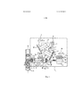
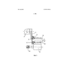
фигура 1. Вид сверху согласно изобретению шлифовального станка в принципиальном изображении;figure 1. Top view according to the invention of the grinding machine in the principal image;
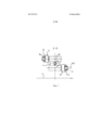
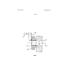
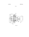
фигура 2. Вид в частичном разрезе плоскости сечения A-A для бабки изделия по фигуре 1;figure 2. A view in partial section of a plane section A-A for the headstock of the product according to figure 1;
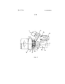
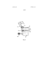
фигура 3. Принципиальное изображение одновременного врезания профилированного шлифовального круга первой шлифовальной бабки и внутреннего шлифовального круга второй шлифовальной бабки;figure 3. The principal image of the simultaneous insertion of a profiled grinding wheel of the first grinding headstock and the inner grinding wheel of the second grinding headstock;
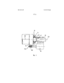
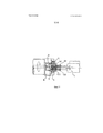
фигура 4. Положение второй шлифовальной бабки, в которой зажимное устройство размещено относительно центральной оси зажимного устройства бабки изделия и незадолго до введения в сверление изделия;figure 4. The position of the second grinding headstock, in which the clamping device is placed relative to the Central axis of the clamping device of the headstock of the product and shortly before the introduction into the drilling of the product;
фигура 5. Следующее за положением согласно фигуре 4 положение второй шлифовальной бабки при вошедшем в сверление изделия и находящемся в положении зажима зажимном устройстве;figure 5. Following the position according to figure 4, the position of the second grinding headstock when included in the drilling product and is in the clamping position of the clamping device;
фигура 6. Зажатое в сверлении посредством зажимного устройства изделие при шлифовании прямоходным способом шлифования противоположной плоской стороны;figure 6. Clamped in the drilling by means of a clamping device, the product when grinding a straight-line method of grinding the opposite flat side;
фигура 7. Увеличенное изображение шлифования противоположной плоской стороны посредством прямоходного шлифовального круга;figure 7. An enlarged image of grinding the opposite flat side by means of a linear grinding wheel;
фигура 8. Шлифование противоположной плоской стороны посредством способа шлифования под углом или шлифовального круга для шлифования под углом;Figure 8. Grinding the opposite flat side by an angle grinding method or an angle grinding wheel;
фигура 9. Внутреннее шлифование сверления изделия посредством внутреннего шлифовального круга с участком чернового и чистового шлифования при одновременной подаче смазывающе-охлаждающей жидкости через бабку изделия к шлифуемому участку; иFigure 9. Internal grinding of a product by means of an internal grinding wheel with a rough and finish grinding section while supplying a cutting fluid through the headstock to the surface to be grinded; and
фигура 10. Внутреннее шлифование сверления с помощью внутреннего шлифовального круга с участком чернового и чистового шлифования при черновом шлифовании способом однопроходного шлифования и чистовом шлифовании способом врезного шлифования.figure 10. Internal grinding of drilling using an internal grinding wheel with a section of rough and finish grinding during rough grinding by the method of single pass grinding and finish grinding by the method of mortise grinding.
На фигуре 1 в принципиальном изображении показан вид сверху согласно изобретению шлифовального станка, осуществляющего также согласно изобретению способ. На станине 1 расположены первая шлифовальная бабка 2, вторая шлифовальная бабка 17 и бабка 9 изделия, существующие в определенном отношении друг к другу. Первая шлифовальная бабка 2 несет первый шлифовальный шпиндель 3, на котором установлен шлифовальный круг 3.1. На первой шлифовальной бабке 2 установлен другой шлифовальный шпиндель 4, на котором базируется другой шлифовальный круг 4.1. Шлифовальный круг 4.1 профилирован и служит для шлифования первых плоских внешних поверхностей 14.1, а также неплоских внешних поверхностей 14.4 изделия 14, закрепленного в зажимном устройстве 12 первого шпинделя 10 изделия, приводимого во вращение изделие 14 посредством управляемой компьютерным программным управлением оси C1. Профилированный шлифовальный круг 4.1 вводится в контакт для шлифования c изделием 14 посредством компьютерного программного управления осей X1 и Z1 первого узла 2 шлифовального шпинделя.Figure 1 in a schematic image shows a top view according to the invention of a grinding machine, also carrying out according to the invention a method. On the bed 1 are located the first grinding
Первая шлифовальная бабка 2 имеет, кроме того, вертикально проходящую в плоскости чертежа ось B, поэтому посредством поворотного движения вокруг оси B шлифовальной бабки 2 выборочно в контакт с изделием могут приводиться профилированный шлифовальный круг 4.1 или шлифовальный круг 3.1. Шлифовальный круг 3.1 предусмотрен для шлифования второй плоской внешней поверхности 14.2 на изделии. В показанном на фигуре 1 изображении вторая плоская внешняя поверхность 14.2 зажата внутри зажимного устройства 12 шпинделя 10 изделия, а поэтому не может шлифоваться во время этого закрепленного состояния.The
Профилированный шлифовальный круг 4.1 выполнен и может вводиться контакт для шлифования с шлифуемым внешним профилем так, что, внутренний шлифовальный круг 19.1, расположенный на второй шлифовальной бабке 17 со шлифовальным шпинделем 19, по меньшей мере, частично параллельно по времени, можно устанавливать в сверление 14.3 изделия 14, поэтому сверление 14.3 изделия можно шлифовать вчистовую, не теряя вследствие этого продолжительности такта. В противоположность этому, в шлифовальных станках или способах согласно уровню техники операции по шлифованию на внешних поверхностях и во внутренней поверхности выполняют по очереди.The shaped grinding wheel 4.1 is made and a grinding contact can be made with the external profile to be grinded so that the internal grinding wheel 19.1 located on the second grinding
Вторая шлифовальная бабка 17 выполнена в виде комбинированного узла, в то время, как на шлифовальной бабке смонтировано дополнительное зажимное устройство 20, которое с одной стороны, может перемещаться, посредством регулируемых компьютерным цифровым программным управлением осей X2 и Z2 со шлифовальной бабкой 17 в плоскости X2-Z2, причем дополнительно зажимное устройство 20 может получать осевое перемещение 21 вдоль центральной оси 20.1.The
После того, как плоские внешние поверхности 14.1 и неплоские внешние поверхности 14.2, а также внутренняя поверхность сверления 14.3 отшлифованы вчистовую, шлифовальная бабка 17 перемещается в направлении X2 относительно своей центральной оси настолько, что центральная ось 20.1 зажимного устройства 20 располагается с центральной осью 10.1 шпинделя 10 изделия бабки 9 изделия на одной прямой. В этом положении шлифовальной бабки 17 зажимное устройство 20 входит в сверление 14.3 и захватывает изделие в виде зажима. При этом изделие зажато на протяжении определенного, относительно короткого времени, как в зажимном патроне 12 бабки 9 изделия, так посредством зажима зажимным устройством 20. После осуществленного зажима изделия 14 посредством зажимного устройства 20, зажимной патрон 12 бабки 9 изделия разъединяется и вторая шлифовальная бабка 17 перемещается. Вследствие этого открывается вторая плоская внешняя поверхность 14.4, поэтому посредством первой шлифовальной бабки 2 шлифовальный круг 3.1 может входить в положении для шлифования. Шлифовальный круг 3.1 выполнен как торцовый шлифовальный круг, поэтому вторую плоскую внешнюю поверхность 14.2 выполняют способом прямого врезного шлифования. Это позволяет шлифовать вчистовую передние, а также задние внешние стороны и внутренние поверхности сверления изделия, в частности, в виде шестерни для привода, на одном и том же шлифовальном станке. Это может обеспечивать изготовление отдельных отшлифованных партий изделий с небольшими отклонениями друг от друга по допуску на размер, заданного положения и геометрической форме.After the flat outer surfaces 14.1 and the non-planar outer surfaces 14.2, as well as the inner drilling surface 14.3, are polished cleanly, the grinding
Бабка 9 изделия выполнена так, что имеются два шпинделя, расположенные в бабке 9 изделия в 180° компоновке напротив друг друга. На чертеже справа предусмотрен шпиндель 10 изделия со своей центральной осью 10.1 и с установленным на нем зажимным патроном 12. На фигуре 1, в левой стороне, предусмотрен второй шпиндель 11 изделия со своей центральной осью 11.1 и зажимным патроном 13. В то время как шпиндель изделия со своим зажимным патроном 12 закрепил уже отшлифованное или также отшлифованное вчистовую изделие 14, с помощью второго шпинделя 11 изделия, т.е. с помощью зажимного патрона 13 уже закреплено еще не отшлифованное изделие 15. Изделие 15 может приводиться в движение вторым шпинделем 11 изделия посредством управляемой компьютерным программным управлением оси C2. Бабка 9 изделия теперь расположена с возможностью поворота так, что только принятое сначала в положении погрузки изделие 15 может переводиться в положение для шлифования. Это осуществляется в очень короткий промежуток времени, благодаря сдвоенной компоновке шпинделей изделия в бабке 9. Вследствие этого достигают минимизации вспомогательного времени в шлифовальном станке.The
На бабке 9 изделия дополнительно установлен правящий шпиндель 16 с правящим диском 16.1, посредством которого могут правиться шлифовальные круги 3.1 и 4.1 первой шлифовальной бабки. Первая шлифовальная бабка 2 имеет другой правящий шпиндель 5 с алмазным правящим диском 6, посредством которого правят внутренний шлифовальный круг 19.1, также называемый заточной оправкой. On the
Рядом со станиной 1 шлифовального станка осуществляется полностью автоматизированный подвод заготовок к шлифовальному станку и отведение готовых деталей от зажимной оправки 20 и от шлифовального станка с помощью не показанной на чертежах вспомогательной системы к подающе-отводящему ленточному транспортеру 22 и от него, расположенному на фигуре 1 с левой стороны рядом со станиной 1 шлифовального станка. Для подвода изделий к шлифовальному станку или их разгрузки из станка, после того, как они отшлифованы вчистовую, предусмотрены специальные манипуляторы, не описываемые в публикации отдельно, так как они не имеют особого значения для данного изобретения. Компоновка двух шпинделей 10, 11 изделия на бабке 9 изделия позволяет проводить погрузку предусмотренных для шлифования новых заготовок изделий 15 во вспомогательное время. Поворот заготовок изделия из положения погрузки продолжается с помощью данной бабки 9 изделия, например, менее, чем две секунды. Погрузка в зажимной патрон 13 в отношении необходимого на это времени некритична, поскольку она может осуществляться в любом случае в более короткое время, чем требуется при шлифовании для полного шлифования изделия 14. Во всяком случае, погрузка в зажимной патрон с закреплением и соответствующими манипуляциями, может происходить, как правило, в течение, примерно восьми секунд. Так как это происходит во вспомогательное время, т.е. во время, в которое обрабатывают изделие 14, можно еще больше сократить продолжительность такта для изделия, что благоприятно сказывается на расходах при изготовлении изделий.Next to the bed 1 of the grinding machine, a fully automated supply of workpieces to the grinding machine and the removal of finished parts from the clamping
На фигуре 2 показан частичный разрез вдоль плоскости A-A согласно фигуре 1, в частности, выполнение компоновки двух шпинделей 10, 11 изделия в бабке 9 изделия. Оба шпинделя 10, 11 изделия могут поворачиваться посредством поворотного узла 23 из положения для шлифования, соответствующего на фиг.2 компоновке изделия 14, в положение погрузки, соответствующее на фиг. 2 изделию 15. В частности, оба шпинделя 10, 11 изделия могут приводиться попеременно в положение обработки. Станина 1 обозначена в этом виде частичного разреза А-A бабки изделия схематически. Вследствие того, что шпиндель 10 изделия, т.е. на фигуре 2 нижний шпиндель изделия для шлифования внешних профилей и внутренних профилей изделия 14 расположен ближе к станине во время контакта для шлифования, диапазон изменения температур шлифовального станка еще более значительно выравнивается, а жесткость всего конструктивного узла также становится больше благодаря усовершенствованному действию рычага. Это позволяет достигать большей точности при обработке шлифованием в отношении максимально достигаемой точности размера и геометрической формы отшлифованного вчистовую изделия. Как уже было показано в связи с описанием фигуры 1, во время обработки шлифованием изделия 14 осуществляется загрузка шпинделя 11 изделия или зажимного патрона 13 новой заготовкой изделия 15. В частности, погрузка происходит во время обработки шлифованием. Погрузочные манипуляции запрограммированы так, что цикл загрузки не совпадает, например, с моментом времени достижения чистового размера изделия 14. Такое специальное программирование позволяет получить дальнейшую оптимизацию достигаемого качества изделия 14 на шлифовальном станке. Погрузка и разгрузка изделия производится в так называемое вспомогательное время. Для осуществления собственного процесса шлифования изделия 14, необходимо осуществить только занимающий небольшое время процесс поворота изделия 15 в положение изделия 14 согласно фигуре 2. Изделие 15 становится, так сказать, изделием 14, когда начинается обработка шлифованием изделия, или когда она закончена полностью. Вследствие этого собственно время для погрузки и разгрузки не имеет значения для продолжительности такта, а только время для поворота из положения погрузки в положение для шлифования.Figure 2 shows a partial section along the plane A-A according to figure 1, in particular, the layout of the two
На фигуре 3 изображен увеличенный фрагмент участка шлифовального станка согласно фигуре 1, показывающий переднюю бабку 10 изделия с зажатым изделием 14, в которой шлифовальный круг 4.1 находится с ним в контакте, а внутренний шлифовальный круг 19.1 на второй шлифовальной бабке 19 также находится в контакте для шлифования внутренней поверхности сверления 14.3. Как это показано на фигуре, во время обработки изделие 14 В неподвижно зажато в зажимном патроне 12. Для точной ориентации и для определения положения по длине в зажимном патроне изделие 14 прилегает к упорному кольцу 24 в зажимном патроне. С такой базовой плоскостью неподвижно зажатое посредством шпинделя 10 изделия в зажимном патроне 12 и приводимое во вращение компьютерным программным управлением изделие 14 шлифуют в отношении его внешнего профиля в виде первых плоских внешних поверхностей 14.1 и неплоских внешних поверхностей 14.4 посредством профилированного внешнего шлифовального круга 4.1 в шлифовальном шпинделе 4. Одновременно с помощью внутреннего шлифовального круга 19.1, приводимого во вращение установленным на второй шлифовальной бабке 17 шлифовальным шпинделем19, шлифуют сверление 14.3 изделия 14. Эти оба этапа обработки могут проводиться, по меньшей мере, частично или также полностью равномерно. Последнее соответствует, само собой разумеется, только тогда, если продолжительности обработки почти одинаковые по времени для обоих технологических процессов. Параллельная по времени обработка внешних поверхностей 14.1 и 14.4, а также сверления 14.3 приводит к уменьшенной продолжительности обработки или продолжительности такта, а вместе с ними - к уменьшенной стоимости изделий. Так как приводы для внешнего шлифовального круга 4.1, так и для внутреннего шлифовального круга 19.1 приводятся в движение с помощью управления компьютерным программным управлением, обработка в обоих процессах может выполняться, если это должно быть предпочтительно для определенного изделия, также частично или полностью с отсрочкой по очереди. Хотя это и увеличивает, в частности, продолжительность такта, однако, по соображениям технологий шлифования, это очень предпочтительно для определенных изделий.Figure 3 shows an enlarged fragment of a section of the grinding machine according to Figure 1, showing the
На фигуре 3 показано направление подачи внутреннего шлифовального круга 19.1 или шлифовального штифта при шлифовании в направлении стрелки 30. Однако принципиально может быть предпочтительно выполнять направление подачи в противоположном направлении. Это сильно зависит от конструктивного выполнения шлифовального станка. Эти мероприятия позволяют положительно использовать показатели жесткости и температурные дрифты шлифовального станка, поэтому еще более оптимизируются результаты шлифования в отношении точности.Figure 3 shows the feed direction of the inner grinding wheel 19.1 or of the grinding pin when grinding in the direction of
В том же самом корпус, в котором фиксированы шлифовальные шпиндели 19 на второй шлифовальной бабке 17, установлено также зажимное устройство, предпочтительно в виде зажимной оправки (20), показанной в частичном разрезе второй шлифовальной бабки 17. Зажимная оправка с возможностью автоматического осевого перемещения (21) и приведения во вращение. Благодаря выполнению также и второй шлифовальной бабки 17 с возможностью движения вдоль своей оси X2 и Z2, зажимную оправку 20 с соосной ориентацией своей центральной оси 20.1 можно центрировать к центральной оси 10.1 шпинделя 10 изделия и в этом положении осуществлять идентичное с закреплением посредством шпинделя 10 изделия закрепление в отношении пространственного расположения изделия зажимным патроном 12. Это создает возможность для обработки изделия с высокой точностью, так как для каждого из обоих закреплений ограничивается расположение изделия в зажатом положении относительно центральной оси.In the same housing in which the grinding
Шлифование, как внутренним шлифовальным кругом 19.1, так и внешним шлифовальным кругом 4.1 происходит предпочтительно с помощью эльборовой (CBN) накладки, причем предпочтительно используют эльборовую накладку на керамической связке. Конечно, возможно использование также других абразивных средств, например, корундовых или других эльборовых накладок на керамической связке, причем соответствующие оптимальные абразивные покрытия выбирают в зависимости от задачи обработки.Grinding, both with the internal grinding wheel 19.1 and the external grinding wheel 4.1, is preferably carried out using an Elbor (CBN) pad, and preferably an Elbor pad with a ceramic bond is used. Of course, it is also possible to use other abrasive products, for example, corundum or other elboric ceramic bonded linings, the corresponding optimal abrasive coatings being selected depending on the processing task.
В изображенной на фигуре 3 зажимной оправке 20, в частности, на ее левой стороне, на ее конечном участке, предусмотренном собственно для закрепления изделия 14 в сверлении 14.3, показан зажимной элемент 25, автоматически закрываемый и открываемый, т.е. зажимаемый согласно программе шлифования. В данном случае показан гидротензометрический зажимной элемент. Такой гидротензометрический зажимной элемент растягивается для активации зажимания при подводе гидравлической рабочей среды. Для разгрузки соответственно снижают давление гидравлической рабочей среды. Разумеется, возможны также другие зажимные элементы, например, зажимные цанги или даже внутренний зажимной патрон, т.е. механический патрон.In the clamping
В фигуре 4 закончена чистовая обработка плоских и неплоских внешних поверхностей 14.1, 14.4, а также внутренних поверхностей сверления 14.3 изделия 14, а шлифовальная бабка 17 перемещена посредством управляемых компьютерным программным управлением осей так, что внутренний шлифовальный круг 19.1 расположен параллельно к центральной оси 10.1 шпинделя изделия таким образом, что зажимная оправка 20 непосредственно находится перед сверлением 14.3 изделия 14 для ее непосредственной установки в конечном счете в соответствии со своим осевым перемещением 21 с целью закрепления в это сверление 14.3. Для этого геометрию шпинделя 10 изделия, также, как шлифовального шпинделя 19 для внутреннего шлифовального круга 19.1 выбирают такой, чтобы отсутствовали мешающие контуры между передней бабкой изделия и шлифовальным шпинделем 19 или внутренним шлифовальным кругом 19.1.In figure 4, finishing of the flat and non-planar external surfaces 14.1, 14.4, as well as the internal drilling surfaces 14.3 of the
Для получения усовершенствованного распределения смазывающе-охлаждающей жидкости также во внутреннем шлифовальном круге 19.1 или в шлифовальном штифте при подводе смазывающе-охлаждающей жидкости через шпиндель 10 изделия, предпочтительно оснастить шлифовальный штифт коническим выступом 19.2.In order to obtain an improved distribution of cutting fluid also in the internal grinding wheel 19.1 or in the grinding pin when supplying the cutting fluid through the
Затем на фигуре 5 показан, по сравнению с фигурой 4, момент, когда зажимная оправка 20 установлена после своего осевого перемещения 21 в сверление 14.3 и изделие 14 закреплено в нем. Для этого закрепление выполняют так, что центральная ось зажимной оправки 20.1 точно располагается на одной прямой с центральной осью 10.1 шпинделя 10 изделия. В этот момент изделие закреплено, так сказать, двукратно, как с зажимным патроном 12 шпинделя 10 изделия, так и с помощью зажимной оправки 20 шлифовальной бабки 17. Только после осуществления полного закрепления изделия 14 посредством зажимной оправки 20 в сверлении 14.3, зажимной патрон 12 отделяется от изделия 14, а шлифовальная бабка 17 перемещается вдоль управляемой компьютерным программным управлением оси, в частности, на фигуре 5 направо.Then, figure 5 shows, in comparison with figure 4, the moment when the clamping
Охватывание и передача изделия 14 от зажимного патрона 12 на зажимную оправку 20 может осуществляться при неподвижном или вращающемся шпинделе 10 изделия. При охватывании вращающимся шпинделем изделия 10 зажимная оправка 20 также должна вращаться с одинаковой скоростью вращения и в оном направлении вращения. Это оптимизирует время охватывания.The coverage and transfer of the
Когда шлифовальная бабка 17 с изделием 14 переместилась (смотри фиг. 6), шлифуют вторую плоскую внешнюю поверхность 14.2 с помощью внешнего шлифовального круга 3.1, фиксированном на соответствующем шлифовальном шпинделе 3 и приводимым им в движение, так как изделие 14 теперь полностью надежно и точно закреплено зажимной оправкой 20 во внутреннем сверлении посредством гидроизометрического зажимного элемента 25. Если изделие закреплено с помощью зажимной оправки 20 и она приводит изделие во вращение, что изображено вращающейся по кругу стрелкой на правой стороне, шлифуют точно также приводимым в движение внешним шлифовальным кругом 3.1 вторую плоскую внешнюю поверхность 14.2. В этом положении внутренний шлифовальный круг 19.11 со своим шлифовальным шпинделем 19, так сказать, отъехал в сторону и выведен из зацепления.When the grinding
Зажимная оправка выполнена так, что ее радиальные биения составлят в целом всего лишь несколько мкм. Вследствие этого, этим способом и с помощью этого шлифовального станка можно изготавливать с высокой точностью изделия на единственном шлифовальном станке, на одном и том же шлифовальном станке в смысле полной обработки обеих сторон изделия.The clamping mandrel is designed so that its radial runout is a total of only a few microns. As a result of this, in this way and with the help of this grinding machine, it is possible to produce products with high accuracy on a single grinding machine, on the same grinding machine in the sense of complete processing of both sides of the product.
В зависимости от формы изделия 14 также возможно, что на противоположной плоской стороне 14.2 можно шлифовать неплоские внешние поверхности. В таком случае, например, вместо прямоходного шлифовального круга 3.1 используют профилированный шлифовальный круг, в частности, в виде показанного на фигуре 3 внешнего шлифовального круга 4.1.Depending on the shape of the
На фигуре 7, в увеличенном изображении, показано положение обработки согласно фигуре 6, причем в дополнение вторая плоская внешняя поверхность 14.2 выполнена с уступом. Разумеется, что торцовым шлифовальным кругом 3.1 можно надежно шлифовать обе части плоской внешней поверхности 14.2.Figure 7, in an enlarged image, shows the position of the processing according to figure 6, and in addition the second flat outer surface 14.2 is made with a step. Of course, that the face grinding wheel 3.1 can reliably grind both parts of a flat outer surface 14.2.
На фигуре 8 показано положение для шлифования второй плоской внешней поверхности 14.2 по аналогии с фигурой 6, однако, посредством внешнего шлифовального круга 3.1, используемого способом шлифования под углом. Этот внешний шлифовальный круг 3.1 расположен в этом случае при соответствующей компоновке со своим шлифовальным шпинделем 3 на первой шлифовальной бабке 2 (на чертеже не показано). С помощью такой компоновки можно дополнительно шлифовать также неплоские внешние поверхности на противоположной плоской стороне, т.е. при необходимости цилиндрические или конические участки изделия на его второй стороне, для чего используют либо внешний шлифовальный круг 3.1, либо профилированный шлифовальный круг в соответствии с его используемым на фигуре 3 вариантом выполнения, однако, при другой соответствующей угловой компоновке или подаче. Способ обработки противоположной плоской стороны прямым врезным шлифованием или шлифования под углом, зависит от необходимой задачи шлифования и, естественно, также от геометрии изделия 14. Согласно изобретению, шлифовальный станок согласовывают в каждом случае отдельно относительно этого с изделием и с задачей шлифования, без какого-либо другого изменения изображенной на фигуре 1 принципиальной конструкции.The figure 8 shows the position for grinding the second flat outer surface 14.2 by analogy with figure 6, however, by means of an external grinding wheel 3.1, used by the method of grinding at an angle. This external grinding wheel 3.1 is located in this case with the corresponding layout with its grinding
На фигуре 9 показан другой предпочтительный вариант выполнения шлифовального станка при шлифовании сверления 14.3 изделия 14 посредством внутреннего шлифовального круга 19.1. Для наглядности на чертеже внешний шлифовальный круг 4.1 (смотри фигуру 3) опускался. Внутренний шлифовальный круг 19.1 выполнен в виде заточной оправки и имеет два участка 19.1.1 и 19.1.2 шлифования с разными абразивными покрытиями. Первое, набегающее вперед абразивное покрытие 19.1.1 служит для чернового шлифования поверхностей сверления 14.3, а второе, отстающее абразивное покрытие 19.1.2 служит для чистового шлифования сверления. Так как диаметр второго абразивного покрытия 19.1.2 больше первого абразивного покрытия 19.1.1, шлифовальную бабку 17 со шлифовальными шпинделями 19 после окончания чернового шлифования посредством первого абразивного покрытия 19.1.1 переставляют поперек центральной оси в соответствии с осью X2, и этот второй участок 19.1.2 шлифования входит в сверление для чистового шлифования. Первый участок 19.1.1 шлифования выступает затем в свободное пространство внутри шпинделя 10 изделия.Figure 9 shows another preferred embodiment of a grinding machine when grinding drilling 14.3 of
Как правило, кругом для чернового шлифования должен являться находящийся дальше всего от опоры шпинделя круг. Такие двухступенчатые внутренние шлифовальные круги 19.1 используют, прежде всего, тогда, когда сверление 14.3 изделия имеет, например, увеличенные припуски шлифования или припуски под шлифование из предварительной обработки сильно колеблются. Это черновое шлифование может быть также предпочтительным, в зависимости от того, какой материал нужно разрезать.As a rule, the rough grinding wheel should be the wheel farthest from the spindle support. Such two-stage internal grinding wheels 19.1 are used, first of all, when the drilling 14.3 of the product has, for example, increased grinding allowances or grinding allowances from pre-treatment vary greatly. This rough grinding may also be preferred, depending on which material needs to be cut.
Также и в этом случае для чистового шлифования используют эльборовое абразивное покрытие 19.1.2 на керамической связке, что позволяет достигать соответствующей хорошей чистоты обработки поверхности и высокой точности. Для чернового шлифования можно также применять эльборовое покрытие на керамической связке, но также и абразивное покрытие 19.1.1 с эльборовым покрытием, нанесенным гальваническим способом. Шлифовальные круги с гальваническим способом нанесенным эльборовым покрытием имеют, как правило, более высокую производительность резания, а вследствие этого они особенно хорошо подходят для процессов чернового шлифования. Такой двухступенчатый внутренний шлифовальный круг 19.1 обеспечивает оптимизацию процесса шлифования и достижения точности при одинаковом техническом выполнении станка.Also in this case, for finish grinding, an elbor abrasive coating 19.1.2 on a ceramic bond is used, which allows to achieve a corresponding good surface finish and high accuracy. For rough grinding, you can also use an elbor coating with a ceramic bond, but also an abrasive coating 19.1.1 with an elbor coating, applied by a galvanic method. Electroplated grinding wheels generally have higher cutting performance, and as a result, they are particularly well suited for rough grinding processes. Such a two-stage internal grinding wheel 19.1 provides optimization of the grinding process and achievement of accuracy with the same technical performance of the machine.
Во время шлифования находящегося в контакте шлифовального круга 19.1 необходимо подводить к нему смазывающе-охлаждающую жидкость 26. Согласно этому примеру выполнения смазывающе-охлаждающую жидкость 26 подводят через внутреннюю часть шпинделя 10 изделия и собственно к контакту для шлифования. Для сохранения более лучшего распределения смазывающе-охлаждающей жидкости 26, передняя часть, т.е. участок 19.1.1 чернового шлифования внутреннего шлифовального круга 19.1 может иметь коническую насадку для более лучшего распределения смазывающе-охлаждающей жидкости 26. Хотя такая коническая насадка может отсутствовать. Преимущество такой конической насадки 27 на переднем конце внутреннего шлифовального круга 19.1 состоит в уменьшенном завихрении смазывающе-охлаждающей жидкости 26 при подводе к шлифуемому участку, что обеспечивает более лучшее снабжение зоны шлифования смазывающе-охлаждающей жидкостью, а вследствие этого и условия для шлифования. В результате это положительно сказывается на точности результата шлифования и структуре поверхности отшлифованного вчистовую изделия.During grinding of the grinding wheel 19.1 in contact, it is necessary to supply a lubricant-cooling
На фигуре 10 показан другой предпочтительный вариант выполнения аналогичный фигуре 9, в котором внутренний шлифовальный круг 19.1 также двухступенчатый, снабженный первым, набегающим вперед участком 19.1.1 шлифования и вторым, отстающим участком 10.1.2 шлифования. Первый, набегающий вперед участок 19.1.1 шлифования имеет больший диаметр, чем второй, отстающий участок 19.1.2 шлифования. Первый участок 19.1.1 шлифования выполнен значительно уже, чем второй участок 19.1.2 шлифования, поэтому участком 19.1.1 чернового шлифования способом однопроходного шлифования можно отшлифовывать относительно большой припуск, причем целесообразно использовать в качестве абразивного покрытия эльборовое покрытие на керамической связке. После окончания чернового шлифования, внутренний шлифовальный круг 19.1 перемещается в сверление своим вторым участком 19.1 шлифования настолько, чтобы сверление можно было шлифовать вчистовую способом внутреннего шлифования, в частности, также и способом врезного шлифования. Для этого первый участок 19.1.1 шлифования перемещается в свободное пространство внутри шпинделя 10 изделия настолько, чтобы второй участок 19.1.2 шлифования можно было подать по оси X2 шлифовального шпинделя 19 в шлифуемую внутреннюю поверхность сверления 14.3.Figure 10 shows another preferred embodiment, similar to Figure 9, in which the inner grinding wheel 19.1 is also two-stage, equipped with a first, grinding forward section 19.1.1 and a second, grinding lagging section 10.1.2. The first grinding section 19.1.1 running forward has a larger diameter than the second grinding section 19.1.2 lagging behind. The first grinding section 19.1.1 is made much narrower than the second grinding section 19.1.2; therefore, the rough grinding section 19.1.1 can be ground with a single-pass grinding method with a relatively large allowance, and it is advisable to use an elbor coating on a ceramic bond as an abrasive coating. After rough grinding is completed, the inner grinding wheel 19.1 is moved into the drilling with its second grinding section 19.1 so that the drilling can be sanded off-site using the internal grinding method, in particular, also the mortise grinding method. For this, the first grinding section 19.1.1 is moved into the free space inside the
Передний участок 19.1.1 шлифования внутреннего шлифовального круга также имеет коническую насадку 27, служащую для более равномерного распределения смазывающе-охлаждающей жидкости 26 к соответствующему месту контакта для шлифования.The front grinding section 19.1.1 of the internal grinding wheel also has a
Изображенные в зажимном патроне 12 на зажимных кулачках стрелки должны отображать, что зажимной патрон фиксирует изделие 14 в зажатом состоянии, пока обрабатываются шлифуемые поверхности.The arrows depicted in the
В этом варианте выполнения чернового шлифования можно оптимизировать время шлифования изделия посредством чернового шлифования с помощью первого участка 19.1.1 шлифования при направлении подачи внутреннего шлифовального круга 19.1 в направлении зажимного патрона 12 в зажатом изделии 14 таким образом, что движение ввода шлифовального штифта 19.1 уже используется для чернового шлифования. Это выполнение допускает шлифование вчистовую с очень небольшим припуском шлифования вторым участком 19.1.2 шлифования внутреннего шлифовального круга 19.1. В целом, это оптимизирует общее время шлифования для сверления 14.3.In this rough grinding embodiment, it is possible to optimize the grinding time of the product by rough grinding with the first grinding section 19.1.1 in the feed direction of the inner grinding wheel 19.1 in the direction of the
При объединении шлифовальной бабки, в данном случае для внутреннего шлифования, и зажимного устройства в единственный узел устройства, используются необходимые для высокой точности зажимного устройства преимущества требующего, кроме того, большой прочности шлифовального шпинделя для обеих частей комбинированного устройства.When combining the grinding headstock, in this case, for internal grinding, and the clamping device into a single unit of the device, the advantages necessary for high precision clamping device are used, which also require the high strength of the grinding spindle for both parts of the combined device.
Claims (23)
Applications Claiming Priority (3)
| Application Number | Priority Date | Filing Date | Title |
|---|---|---|---|
| DE102014203402.7A DE102014203402B3 (en) | 2014-02-25 | 2014-02-25 | GRINDING MACHINE AND METHOD FOR GRINDING AXIAL HOLES AND BOTH WORKPIECES APPLICABLE TO WORK ON THE SURFACE |
| DE102014203402.7 | 2014-02-25 | ||
| PCT/EP2015/053121 WO2015128210A1 (en) | 2014-02-25 | 2015-02-13 | Grinding machine and method for grinding workpieces that have axial bores and planar external surfaces to be machined on both sides |
Publications (3)
| Publication Number | Publication Date |
|---|---|
| RU2016137818A RU2016137818A (en) | 2018-03-29 |
| RU2016137818A3 RU2016137818A3 (en) | 2018-06-28 |
| RU2663503C2 true RU2663503C2 (en) | 2018-08-07 |
Family
ID=52473914
Family Applications (1)
| Application Number | Title | Priority Date | Filing Date |
|---|---|---|---|
| RU2016137818A RU2663503C2 (en) | 2014-02-25 | 2015-02-13 | Grinding machine and method of grinding axial drilling and bilateral treatment flat external surface products |
Country Status (9)
| Country | Link |
|---|---|
| US (1) | US10058968B2 (en) |
| EP (1) | EP3110594B1 (en) |
| JP (1) | JP6469715B2 (en) |
| CN (1) | CN106061676B (en) |
| BR (1) | BR112016017435B1 (en) |
| DE (1) | DE102014203402B3 (en) |
| ES (1) | ES2664172T3 (en) |
| RU (1) | RU2663503C2 (en) |
| WO (1) | WO2015128210A1 (en) |
Families Citing this family (36)
| Publication number | Priority date | Publication date | Assignee | Title |
|---|---|---|---|---|
| JP6445257B2 (en) * | 2014-06-04 | 2018-12-26 | Ntn株式会社 | Cylindrical workpiece machining method and machining apparatus |
| DE102015206082A1 (en) * | 2015-04-02 | 2016-10-06 | Mahle International Gmbh | grinding machine |
| DE102015211115B4 (en) * | 2015-06-17 | 2022-11-03 | Erwin Junker Maschinenfabrik Gmbh | Process and grinding machine for grinding the external and internal contours of workpieces in one setting |
| DE102015010942B4 (en) * | 2015-08-18 | 2023-11-09 | Emag Holding Gmbh | Method and device for grinding and precision machining |
| JP2017080867A (en) * | 2015-10-30 | 2017-05-18 | トーヨーエイテック株式会社 | Grinding device |
| DE102016204273B4 (en) * | 2016-03-15 | 2023-11-30 | Erwin Junker Maschinenfabrik Gmbh | METHOD FOR COMPLETE GRINDING OF WAVE-SHAPED WORKPIECES WITH CYLINDRICAL AND PROFILED SECTIONS |
| DE102016009469A1 (en) * | 2016-08-03 | 2018-02-08 | Audi Ag | Method and device for hard fine machining of internally toothed gears by means of a gear honing machine |
| DE102017000681B4 (en) | 2017-01-26 | 2018-11-15 | KAPP Werkzeugmaschinen GmbH | A method for the combined finishing of at least one profile and at least one functional surface of a workpiece on a machine tool |
| CN107350952B (en) * | 2017-08-18 | 2023-04-18 | 江门市盈德钢化玻璃制品有限公司 | Automatic polishing machine for steel rings |
| DE102017217130B4 (en) * | 2017-09-26 | 2025-12-11 | Robert Bosch Gmbh | Grinding tool for internal cylindrical peel grinding |
| CN107584388A (en) * | 2017-10-24 | 2018-01-16 | 浙江晟禧精密机械科技有限公司 | A kind of steel ball deploys wheel grinding machine |
| DE102018001869A1 (en) | 2018-03-07 | 2019-09-12 | Neumayer Tekfor Engineering Gmbh | Device for the mechanical machining of a workpiece |
| EP3801964B1 (en) * | 2018-05-25 | 2024-09-11 | The Gleason Works | Multi-tool chamfering device for toothed workpieces |
| JP7202403B2 (en) * | 2018-06-27 | 2023-01-11 | ビリアン ケンネマン、ロニー | Straightening device for rotary tools |
| CN109202561B (en) * | 2018-09-17 | 2020-09-01 | 芜湖市天宏精密锻造有限公司 | Rolling bearing inner ring or outer ring grinding device |
| CN110421483B (en) * | 2018-12-04 | 2024-04-30 | 西安成立航空制造有限公司 | Clamping mechanism based on accurate tiny part of hole location grinding |
| CN109909816A (en) * | 2019-03-06 | 2019-06-21 | 苏州市乾丰造纸机械制造有限公司 | The double bistrique knife sharpeners of lower edge |
| CN110124821B (en) * | 2019-05-18 | 2020-11-06 | 池州灵芝化建材料科技有限公司 | Automatic mesh-dividing grinding and collecting device for raw ore and using method |
| WO2021144771A1 (en) * | 2020-01-17 | 2021-07-22 | L. Kellenberger & Co. Ag | Apparatus and method for grinding of materials such as metal comprising a handling system adapted to automatically exchange and dress tools |
| WO2021212029A1 (en) * | 2020-04-17 | 2021-10-21 | Amsted Rail Company, Inc. | Systems and methods for polishing a cylindrical lip-seal surface |
| CN112847030A (en) * | 2021-01-08 | 2021-05-28 | 戴鸿 | Grinding device for machining |
| CN112847050B (en) * | 2021-01-14 | 2024-05-14 | 福建省德化县帝窑陶瓷有限公司 | Semitransparent environment-friendly ceramic sheet grinding structure |
| CN113334162A (en) * | 2021-06-25 | 2021-09-03 | 徐州大泰机电科技有限公司 | Installation equipment of polishing of electric automobile rear axle pipe |
| CN113714911A (en) * | 2021-09-01 | 2021-11-30 | 杭州富阳锋拓机械有限公司 | Metal ring machining system |
| GB2613826A (en) * | 2021-12-16 | 2023-06-21 | Fives Landis Ltd | A machine tool for machining workpieces and methods of operation thereof |
| CN115139162B (en) * | 2022-09-06 | 2022-11-18 | 烟台汇金精密机械有限公司 | Multifunctional lathe for steel pipe machining |
| CN116000715B (en) * | 2023-03-23 | 2023-05-30 | 河北海蓝轴承制造有限公司 | Bearing ring grinding device |
| CN117001444A (en) * | 2023-06-08 | 2023-11-07 | 包头美科硅能源有限公司 | A square silicon rod reciprocating grinding process |
| CN116619153A (en) * | 2023-06-19 | 2023-08-22 | 深圳市神州数控机床有限公司 | Composite horizontal numerically controlled grinder capable of grinding inner and outer round composite materials simultaneously |
| CN117020769A (en) * | 2023-08-30 | 2023-11-10 | 安庆市月岭塑业有限公司 | PVC pipeline polisher |
| CN119658536A (en) * | 2023-09-21 | 2025-03-21 | 中国石油天然气集团有限公司 | A steel pipe spiral weld excess height grinding device |
| CN118123657B (en) * | 2024-04-30 | 2024-07-19 | 江苏晨光数控机床有限公司 | Ultra-precise numerical control universal grinding machine |
| CN118744363B (en) * | 2024-07-30 | 2025-10-14 | 马鞍山市恒永利机械科技有限公司 | Workpiece inner hole processing equipment |
| CN119734156B (en) * | 2024-12-02 | 2025-11-11 | 宝鸡法士特齿轮有限责任公司 | Universal spindle slide block machining device and method |
| CN119658427B (en) * | 2024-12-05 | 2026-01-09 | 宁夏天地奔牛实业集团有限公司 | Positioning and clamping tool for machining tail movable upper edge and machining method for tail movable upper edge |
| CN120439127B (en) * | 2025-05-27 | 2025-11-18 | 昆山仁杰飞精密电子有限公司 | A precision machining and grinding equipment for motor shafts |
Citations (4)
| Publication number | Priority date | Publication date | Assignee | Title |
|---|---|---|---|---|
| SU1416294A1 (en) * | 1983-04-05 | 1988-08-15 | Институт За Металорежещи Машини (Инопредприятие) | N/c cylindrical grinder for external and internal grinding |
| DE3817161A1 (en) * | 1987-05-20 | 1988-12-01 | Tsnii Metalorezh Mash | CIRCULAR GRINDING MACHINE WITH NUMERICAL CONTROL FOR GRINDING CHUCK AND TOP WORKPIECES |
| RU2090338C1 (en) * | 1994-10-05 | 1997-09-20 | Самарский государственный технический университет | Cutter grinding method |
| DE60303672T2 (en) * | 2002-03-18 | 2006-10-19 | Miyano Machinery Japan Inc., Ueda | MACHINE TOOL |
Family Cites Families (28)
| Publication number | Priority date | Publication date | Assignee | Title |
|---|---|---|---|---|
| US3646708A (en) * | 1967-01-09 | 1972-03-07 | Robert S Jones | Grinding machinery and methods |
| US4005552A (en) * | 1974-10-21 | 1977-02-01 | Tri-Ordinate Corporation | Apparatus for improved control of a grinding machine |
| US4051830A (en) * | 1976-05-11 | 1977-10-04 | Cincinnati Milacron, Inc. | Wheel dressing apparatus and method |
| DE3628977A1 (en) * | 1986-08-26 | 1988-03-03 | Buderus Kundenguss | GRINDING MACHINE FOR AUTOMATIC INNER ROUND, PLAN, EXTERNAL ROUND AND / OR INNER AND EXTERNAL THREAD GRINDING |
| JPS63144941A (en) * | 1986-12-05 | 1988-06-17 | Toyoda Mach Works Ltd | Complex grinding device |
| JPH0622788B2 (en) * | 1988-05-16 | 1994-03-30 | オ−クマ株式会社 | Grinder |
| US5044125A (en) * | 1988-09-02 | 1991-09-03 | Cincinnati Milacron-Heald Corp. | Method and apparatus for controlling grinding processes |
| JP2619497B2 (en) * | 1988-09-29 | 1997-06-11 | 豊田工機株式会社 | Grinding device with end face measuring device |
| US5139005A (en) * | 1990-08-14 | 1992-08-18 | The Gleason Works | Universal dressing roller and method and apparatus for dressing cup-shaped grinding wheels |
| DE59201551D1 (en) * | 1992-05-29 | 1995-04-06 | Gildemeister Spa | Multi-spindle lathe. |
| JP2560700Y2 (en) * | 1992-10-28 | 1998-01-26 | トーヨーエイテック株式会社 | Dressing equipment in compound grinding machines |
| DE19513963C2 (en) * | 1995-04-13 | 1998-05-28 | Gildemeister Ag | Numerically controlled lathe with a counter spindle |
| JP3187740B2 (en) * | 1997-02-26 | 2001-07-11 | 光洋機械工業株式会社 | Multi-step grinding machine |
| DE19753797C2 (en) * | 1997-12-04 | 2001-02-22 | Buderus Schleiftechnik | Device for grinding workpieces |
| DE19921785B4 (en) * | 1999-05-11 | 2005-11-24 | Erwin Junker Maschinenfabrik Gmbh | Method for grinding convex running surfaces and outer diameters on shafts with at least one disk-shaped shaft section and grinding machine for carrying out the method |
| DE10234707B4 (en) * | 2002-07-30 | 2007-08-02 | Erwin Junker Maschinenfabrik Gmbh | Method and device for grinding a rotationally symmetrical machine component |
| DE10235808B4 (en) * | 2002-08-05 | 2009-08-20 | Erwin Junker Maschinenfabrik Gmbh | Method and device for grinding a rotationally symmetrical machine component provided with a longitudinal bore |
| JP2005111631A (en) * | 2003-10-09 | 2005-04-28 | Star Micronics Co Ltd | NC automatic lathe |
| DE102005018959B3 (en) * | 2005-04-23 | 2006-08-31 | Emag Maschinenfabrik Gmbh | Internal round and flat grinding process for workpiece involves bringing outer surface of truncated-cone front part into engagement with inner surface of boring |
| DE102007009843B4 (en) * | 2007-02-28 | 2010-04-08 | Erwin Junker Maschinenfabrik Gmbh | Method for grinding a machine component and grinding machine for carrying out the method |
| DE102007030956A1 (en) * | 2007-07-04 | 2009-01-08 | The Gleason Works | Slide arrangement for a machine tool |
| JP5428740B2 (en) * | 2009-10-19 | 2014-02-26 | 株式会社ジェイテクト | Compound grinding machine |
| JP5402546B2 (en) * | 2009-11-11 | 2014-01-29 | 株式会社ジェイテクト | Cylindrical workpiece grinding method |
| JP5440159B2 (en) * | 2009-12-25 | 2014-03-12 | 株式会社ジェイテクト | Workpiece grinding method and grinding machine |
| JP5505099B2 (en) * | 2010-06-04 | 2014-05-28 | 株式会社ジェイテクト | Grinding method with compound grinder |
| JP5611691B2 (en) * | 2010-07-05 | 2014-10-22 | シチズンマシナリーミヤノ株式会社 | Machine tool and workpiece machining method |
| US8500514B2 (en) * | 2010-12-08 | 2013-08-06 | Koganei Seiki Co., Ltd. | Apparatus and method for processing piston |
| DE102012012331B4 (en) * | 2011-07-28 | 2016-03-03 | Emag Holding Gmbh | machine tool |
-
2014
- 2014-02-25 DE DE102014203402.7A patent/DE102014203402B3/en active Active
-
2015
- 2015-02-13 JP JP2016554230A patent/JP6469715B2/en not_active Expired - Fee Related
- 2015-02-13 RU RU2016137818A patent/RU2663503C2/en active
- 2015-02-13 BR BR112016017435-6A patent/BR112016017435B1/en not_active IP Right Cessation
- 2015-02-13 ES ES15704788.7T patent/ES2664172T3/en active Active
- 2015-02-13 EP EP15704788.7A patent/EP3110594B1/en not_active Not-in-force
- 2015-02-13 US US15/117,535 patent/US10058968B2/en active Active
- 2015-02-13 WO PCT/EP2015/053121 patent/WO2015128210A1/en not_active Ceased
- 2015-02-13 CN CN201580009296.6A patent/CN106061676B/en not_active Expired - Fee Related
Patent Citations (4)
| Publication number | Priority date | Publication date | Assignee | Title |
|---|---|---|---|---|
| SU1416294A1 (en) * | 1983-04-05 | 1988-08-15 | Институт За Металорежещи Машини (Инопредприятие) | N/c cylindrical grinder for external and internal grinding |
| DE3817161A1 (en) * | 1987-05-20 | 1988-12-01 | Tsnii Metalorezh Mash | CIRCULAR GRINDING MACHINE WITH NUMERICAL CONTROL FOR GRINDING CHUCK AND TOP WORKPIECES |
| RU2090338C1 (en) * | 1994-10-05 | 1997-09-20 | Самарский государственный технический университет | Cutter grinding method |
| DE60303672T2 (en) * | 2002-03-18 | 2006-10-19 | Miyano Machinery Japan Inc., Ueda | MACHINE TOOL |
Also Published As
| Publication number | Publication date |
|---|---|
| US10058968B2 (en) | 2018-08-28 |
| JP2017510468A (en) | 2017-04-13 |
| RU2016137818A (en) | 2018-03-29 |
| ES2664172T3 (en) | 2018-04-18 |
| WO2015128210A1 (en) | 2015-09-03 |
| JP6469715B2 (en) | 2019-02-13 |
| CN106061676B (en) | 2019-03-15 |
| RU2016137818A3 (en) | 2018-06-28 |
| DE102014203402B3 (en) | 2015-07-09 |
| US20170252886A1 (en) | 2017-09-07 |
| EP3110594B1 (en) | 2018-01-31 |
| EP3110594A1 (en) | 2017-01-04 |
| BR112016017435B1 (en) | 2021-01-26 |
| CN106061676A (en) | 2016-10-26 |
Similar Documents
| Publication | Publication Date | Title |
|---|---|---|
| RU2663503C2 (en) | Grinding machine and method of grinding axial drilling and bilateral treatment flat external surface products | |
| RU2417148C2 (en) | Method of grinding rod-shape parts, grinding machine tool (versions) and dual grinding section | |
| US8360819B2 (en) | Method for grinding a machine part, and grinding machine for carrying out said method | |
| US6039634A (en) | Hardened workpiece finishing process | |
| US10464182B2 (en) | Method and grinding machine for grinding external and internal contours of workpieces in one clamping | |
| RU2441739C2 (en) | Method and grinding machine for full grinding of short and/or bar-shape processed details | |
| US8678881B2 (en) | Grinding center and method for simultaneous grinding of a plurality of bearings and end-side surfaces of crankshafts | |
| EP2108480B1 (en) | Grinding machine and grinding method | |
| US8500518B2 (en) | Method of grinding an indexable insert and grinding wheel for carrying out the grinding method | |
| RU2711392C2 (en) | Method of grinding complex treatment of shaft-shaped parts with cylindrical and profiled sections | |
| KR20150004296A (en) | Double-side dresser | |
| CN105856032A (en) | Multifunctional full-automatic compound grinding machine | |
| KR100373116B1 (en) | Polishing method and apparatus for cam with concave side | |
| CN106457512A (en) | Method and device for grinding large crankshafts | |
| KR20010033336A (en) | Method and device for polishing workpieces with a simultaneous superfinish | |
| JPH0899242A (en) | Machine tool for combined working | |
| CZ304903B6 (en) | Method of grinding center bearings of crankshafts and apparatus for making the same | |
| CZ294212B6 (en) | Method for grinding exact outside diameters and other surfaces on workpieces, and a grinding machine for carrying out the method | |
| CZ2001487A3 (en) | Grinding machine with turning device for hard-machining | |
| CN205968556U (en) | Multi -functional full -automatic compound grinding machine | |
| US7551974B2 (en) | Processing method of workpieces using combined processing machines | |
| KR101199876B1 (en) | Method and grinding machine for the complete grinding of short and/or rod-shaped workpieces | |
| JP2007196302A (en) | Index type multi-grind grinding machine | |
| BG66427B1 (en) | A method and a machine tool for multi-operational machining of rotary components |