RU2655871C2 - System and method for cutting to length long rolled products coming from different strands of rolling mill - Google Patents
System and method for cutting to length long rolled products coming from different strands of rolling mill Download PDFInfo
- Publication number
- RU2655871C2 RU2655871C2 RU2016103621A RU2016103621A RU2655871C2 RU 2655871 C2 RU2655871 C2 RU 2655871C2 RU 2016103621 A RU2016103621 A RU 2016103621A RU 2016103621 A RU2016103621 A RU 2016103621A RU 2655871 C2 RU2655871 C2 RU 2655871C2
- Authority
- RU
- Russia
- Prior art keywords
- cutting
- threads
- drum
- strands
- guide
- Prior art date
Links
- 238000005520 cutting process Methods 0.000 title claims description 62
- 238000000034 method Methods 0.000 title claims description 6
- 238000005096 rolling process Methods 0.000 title abstract description 15
- 238000005098 hot rolling Methods 0.000 claims description 6
- 125000006850 spacer group Chemical group 0.000 claims description 4
- 125000004122 cyclic group Chemical group 0.000 claims description 2
- 239000002184 metal Substances 0.000 abstract description 6
- 229910052751 metal Inorganic materials 0.000 abstract description 6
- 239000000126 substance Substances 0.000 abstract 1
- 229910000831 Steel Inorganic materials 0.000 description 3
- 238000004519 manufacturing process Methods 0.000 description 3
- 239000010959 steel Substances 0.000 description 3
- -1 ferrous metals Chemical class 0.000 description 2
- CWYNVVGOOAEACU-UHFFFAOYSA-N Fe2+ Chemical compound [Fe+2] CWYNVVGOOAEACU-UHFFFAOYSA-N 0.000 description 1
- 238000009434 installation Methods 0.000 description 1
- 230000003993 interaction Effects 0.000 description 1
- 230000003014 reinforcing effect Effects 0.000 description 1
Images

Classifications
-
- B—PERFORMING OPERATIONS; TRANSPORTING
- B23—MACHINE TOOLS; METAL-WORKING NOT OTHERWISE PROVIDED FOR
- B23D—PLANING; SLOTTING; SHEARING; BROACHING; SAWING; FILING; SCRAPING; LIKE OPERATIONS FOR WORKING METAL BY REMOVING MATERIAL, NOT OTHERWISE PROVIDED FOR
- B23D33/00—Accessories for shearing machines or shearing devices
- B23D33/02—Arrangements for holding, guiding, and/or feeding work during the operation
-
- B—PERFORMING OPERATIONS; TRANSPORTING
- B21—MECHANICAL METAL-WORKING WITHOUT ESSENTIALLY REMOVING MATERIAL; PUNCHING METAL
- B21B—ROLLING OF METAL
- B21B15/00—Arrangements for performing additional metal-working operations specially combined with or arranged in, or specially adapted for use in connection with, metal-rolling mills
- B21B15/0007—Cutting or shearing the product
-
- B—PERFORMING OPERATIONS; TRANSPORTING
- B21—MECHANICAL METAL-WORKING WITHOUT ESSENTIALLY REMOVING MATERIAL; PUNCHING METAL
- B21B—ROLLING OF METAL
- B21B15/00—Arrangements for performing additional metal-working operations specially combined with or arranged in, or specially adapted for use in connection with, metal-rolling mills
-
- B—PERFORMING OPERATIONS; TRANSPORTING
- B23—MACHINE TOOLS; METAL-WORKING NOT OTHERWISE PROVIDED FOR
- B23D—PLANING; SLOTTING; SHEARING; BROACHING; SAWING; FILING; SCRAPING; LIKE OPERATIONS FOR WORKING METAL BY REMOVING MATERIAL, NOT OTHERWISE PROVIDED FOR
- B23D25/00—Machines or arrangements for shearing stock while the latter is travelling otherwise than in the direction of the cut
- B23D25/12—Shearing machines with blades on coacting rotating drums
-
- B—PERFORMING OPERATIONS; TRANSPORTING
- B23—MACHINE TOOLS; METAL-WORKING NOT OTHERWISE PROVIDED FOR
- B23D—PLANING; SLOTTING; SHEARING; BROACHING; SAWING; FILING; SCRAPING; LIKE OPERATIONS FOR WORKING METAL BY REMOVING MATERIAL, NOT OTHERWISE PROVIDED FOR
- B23D36/00—Control arrangements specially adapted for machines for shearing or similar cutting, or for sawing, stock which the latter is travelling otherwise than in the direction of the cut
-
- B—PERFORMING OPERATIONS; TRANSPORTING
- B21—MECHANICAL METAL-WORKING WITHOUT ESSENTIALLY REMOVING MATERIAL; PUNCHING METAL
- B21B—ROLLING OF METAL
- B21B1/00—Metal-rolling methods or mills for making semi-finished products of solid or profiled cross-section; Sequence of operations in milling trains; Layout of rolling-mill plant, e.g. grouping of stands; Succession of passes or of sectional pass alternations
- B21B1/16—Metal-rolling methods or mills for making semi-finished products of solid or profiled cross-section; Sequence of operations in milling trains; Layout of rolling-mill plant, e.g. grouping of stands; Succession of passes or of sectional pass alternations for rolling wire rods, bars, merchant bars, rounds wire or material of like small cross-section
-
- B—PERFORMING OPERATIONS; TRANSPORTING
- B21—MECHANICAL METAL-WORKING WITHOUT ESSENTIALLY REMOVING MATERIAL; PUNCHING METAL
- B21B—ROLLING OF METAL
- B21B15/00—Arrangements for performing additional metal-working operations specially combined with or arranged in, or specially adapted for use in connection with, metal-rolling mills
- B21B15/0007—Cutting or shearing the product
- B21B2015/0014—Cutting or shearing the product transversely to the rolling direction
-
- Y—GENERAL TAGGING OF NEW TECHNOLOGICAL DEVELOPMENTS; GENERAL TAGGING OF CROSS-SECTIONAL TECHNOLOGIES SPANNING OVER SEVERAL SECTIONS OF THE IPC; TECHNICAL SUBJECTS COVERED BY FORMER USPC CROSS-REFERENCE ART COLLECTIONS [XRACs] AND DIGESTS
- Y10—TECHNICAL SUBJECTS COVERED BY FORMER USPC
- Y10T—TECHNICAL SUBJECTS COVERED BY FORMER US CLASSIFICATION
- Y10T83/00—Cutting
- Y10T83/202—With product handling means
- Y10T83/2074—Including means to divert one portion of product from another
- Y10T83/2083—Deflecting guide
-
- Y—GENERAL TAGGING OF NEW TECHNOLOGICAL DEVELOPMENTS; GENERAL TAGGING OF CROSS-SECTIONAL TECHNOLOGIES SPANNING OVER SEVERAL SECTIONS OF THE IPC; TECHNICAL SUBJECTS COVERED BY FORMER USPC CROSS-REFERENCE ART COLLECTIONS [XRACs] AND DIGESTS
- Y10—TECHNICAL SUBJECTS COVERED BY FORMER USPC
- Y10T—TECHNICAL SUBJECTS COVERED BY FORMER US CLASSIFICATION
- Y10T83/00—Cutting
- Y10T83/465—Cutting motion of tool has component in direction of moving work
- Y10T83/4705—Plural separately mounted flying cutters
-
- Y—GENERAL TAGGING OF NEW TECHNOLOGICAL DEVELOPMENTS; GENERAL TAGGING OF CROSS-SECTIONAL TECHNOLOGIES SPANNING OVER SEVERAL SECTIONS OF THE IPC; TECHNICAL SUBJECTS COVERED BY FORMER USPC CROSS-REFERENCE ART COLLECTIONS [XRACs] AND DIGESTS
- Y10—TECHNICAL SUBJECTS COVERED BY FORMER USPC
- Y10T—TECHNICAL SUBJECTS COVERED BY FORMER US CLASSIFICATION
- Y10T83/00—Cutting
- Y10T83/465—Cutting motion of tool has component in direction of moving work
- Y10T83/4714—Oscillating work shifter adjacent cutter
Landscapes
- Engineering & Computer Science (AREA)
- Mechanical Engineering (AREA)
- Metal Rolling (AREA)
- Shearing Machines (AREA)
- Finish Polishing, Edge Sharpening, And Grinding By Specific Grinding Devices (AREA)
Abstract
Description
[0001] Настоящее изобретение относится к системе для разрезания на коммерческие длины разных нитей длинномерного проката из черного металла, выходящего из прокатного стана.[0001] The present invention relates to a system for cutting into commercial lengths of different strands of lengthy rolled ferrous metal leaving the rolling mill.
[0002] Изобретение может применяться, в частности, но не исключительно, в станах горячей прокатки для производства длинномерного проката из черных металлов, такого как пруток, арматура и т.п.[0002] The invention can be applied, in particular, but not exclusively, in hot rolling mills for the production of long rolled products from ferrous metals, such as bars, reinforcing bars, etc.
[0003] Для изготовления готового длинномерного металлического проката, такого как пруток, арматура и пр., в стане, помимо прочих устройств, имеется множество прокатных ручьев, выровненных вдоль линии прокатки для непрерывного прокатывания заготовок, поступающих из печи или другого подобного источника.[0003] For the manufacture of finished long metal products, such as rods, fittings, etc., the mill, among other devices, has many rolling streams aligned along the rolling line for continuous rolling of billets coming from a furnace or other similar source.
[0004] Стан по производству длинномерного проката может быть выполнен с возможностью обработки одновременно нескольких нитей. Нити получают, разделяя или разрезая еще горячее изделие в данной точке стана, например, после заданного количества пропусков прокатки. Разрезание выполняется для повышения производительности стана без увеличения скорости прокатки на последних ручьях. После этой операции разрезания длинномерное металлическое изделие делят на разные нити, которые, затем, должны быть обработаны.[0004] A mill for the production of long products may be configured to process several threads simultaneously. Threads are obtained by dividing or cutting an even hotter product at a given point in the mill, for example, after a given number of passes of rolling. Cutting is performed to increase the productivity of the mill without increasing the rolling speed in the last streams. After this cutting operation, a lengthy metal product is divided into different threads, which, then, must be processed.
[0005] После последнего прокатного ручья изделие обычно разрезают на сегменты прутка, которые затем охлаждают, например, в стеллаже-холодильнике.[0005] After the last rolling stream, the product is usually cut into segments of the bar, which are then cooled, for example, in a refrigerated rack.
[0006] Таким образом, имеется потребность в простом, компактном и эффективном разрезающем средстве для разрезания множества нитей, приходящих с прокатного стана, перед их выгрузкой на стеллаж-холодильник.[0006] Thus, there is a need for a simple, compact and efficient cutting tool for cutting a plurality of threads coming from a rolling mill before unloading them on a refrigerator rack.
[0007] КРАТКОЕ ОПИСАНИЕ ИЗОБРЕТЕНИЯ [0007] SUMMARY OF THE INVENTION
[0008] Вышеописанная проблема решается с помощью системы для разрезания на мерные длины по меньшей мере двух нитей длинномерного проката, предпочтительно выходящих из стана горячей прокатки, при этом система содержит:[0008] The above problem is solved by using a system for cutting into measured lengths of at least two strands of long steel, preferably leaving the hot rolling mill, the system comprising:
- ножницы, содержащие по меньшей мере два вращающихся барабана, каждый из которых имеет режущее средство, расположенное для разрезания одновременно по меньшей мере двух нитей длинномерного проката на готовые сегменты,- scissors containing at least two rotating drums, each of which has a cutting tool located to cut simultaneously at least two strands of lengthy rolled products into finished segments,
- по меньшей мере две подвижные направляющие, каждая из которых содержит по меньшей мере два канала, при этом каждый канал расположен для приема и направления по меньшей мере одной нити длинномерного проката, при этом направляющие выполнены с возможностью перемещения между положением, в котором при работе эти по меньшей мере две нити длинномерного проката расположены вне траектории режущего средства в положении, в котором эти нити не могут быть разрезаны, и положением, в котором эти по меньшей мере две нити расположены на траектории режущего средства, и могут быть разрезаны режущим средством.- at least two movable guides, each of which contains at least two channels, each channel being located for receiving and guiding at least one strand of long rolled products, while the guides are movable between a position in which these at least two strands of long rolled products are located outside the path of the cutting means in a position in which these threads cannot be cut, and in a position in which these at least two strands are located on the path of the cutting of means, and can be cut with a cutting tool.
[0009] Согласно другим признакам изобретения, взятым отдельно или в комбинации:[0009] According to other features of the invention, taken separately or in combination:
[0010] - каждый барабан содержит по меньшей мере два ножа, разнесенных друг от друга и отходящих наружу от внешней стенки барабана;[0010] - each drum contains at least two knives spaced from each other and extending outward from the outer wall of the drum;
[0011] - ножи барабана имеют по существу круговую траекторию, и каждая траектория проходит в параллельных вертикальных плоскостях;[0011] the drum knives have a substantially circular path, and each path passes in parallel vertical planes;
[0012] - по меньшей мере один нож каждого барабана расположен так, чтобы его круговая траектория проходила в одной вертикальной плоскости;[0012] - at least one knife of each drum is located so that its circular path passes in one vertical plane;
[0013] - каждый барабан содержит один нож, каждый нож имеет две режущие поверхности и имеет U-образную форму, определяющую проход для одной или более нити;[0013] - each drum contains one knife, each knife has two cutting surfaces and has a U-shape defining a passage for one or more threads;
[0014] - направляющие выполнены с возможностью вращения между указанными двумя положениями;[0014] - the guides are made to rotate between these two positions;
[0015] - каждая направляющая содержит проставку, проходящую между каждым каналом и горизонтально отделяющую друг от друга каждый канал относительно другого канала этой направляющей;[0015] - each rail contains a spacer extending between each channel and horizontally separating each channel from each other relative to another channel of this rail;
[0016] - каждый барабан имеет по существу цилиндрическую форму с осью, при этом каждая ось расположена в одной вертикальной плоскости и оси проходят параллельно друг другу;[0016] - each drum has a substantially cylindrical shape with an axis, with each axis located in the same vertical plane and the axes parallel to each other;
[0017] - ножи каждого барабана выровнены по линии, параллельной оси барабана;[0017] - the knives of each drum are aligned in a line parallel to the axis of the drum;
[0018] - система содержит множество приводных средств, при этом каждое приводное средство соединено с соединителем направляющей и каждое приводное средство содержит кривошипно-шатунный узел для циклического поступательного перемещения каждой соответствующей направляющей в двух направлениях;[0018] the system comprises a plurality of drive means, wherein each drive means is connected to a guide connector and each drive means comprises a crank assembly for cyclic translational movement of each respective guide in two directions;
[0019] - каждая направляющая далее содержит вал, соединенный с этими двумя каналами, и в которой линейное перемещение провоцирует поворот каждой направляющей вокруг вала между этими двумя положениями;[0019] each guide further comprises a shaft connected to these two channels, and in which linear movement causes each guide to rotate around the shaft between these two positions;
[0020] - первая направляющая расположена перед ножницами, а вторая направляющая расположена после ножниц в направлении движения нитей.[0020] - the first guide is located in front of the scissors, and the second guide is located after the scissors in the direction of movement of the threads.
[0021] Изобретение также относится к способу разрезания на мерные длины по меньшей мере двух нитей длинномерного проката на готовые сегменты, при этом эти по меньшей мере две нити поступают от стана горячей прокатки, и способ содержит этапы, на которых:[0021] The invention also relates to a method for cutting into measured lengths of at least two strands of long products into finished segments, these at least two strands coming from a hot rolling mill, and the method comprises the steps of:
- непрерывно перемещают эти две нити;- continuously move these two threads;
- направляют одновременно эти две нити на траекторию режущих средств, выполненных с возможностью одновременно разрезать эти по меньшей мере две нити;- send simultaneously these two threads on the path of the cutting means, made with the ability to simultaneously cut these at least two threads;
- разрезают одновременно эти по меньшей мере две нити режущими средствами;- cut simultaneously at least two threads with cutting means;
- направляют одновременно эти по меньшей мере две нити из траектории режущих средств.- direct at least these two threads from the path of the cutting means.
[0022] Преимущественно на этапе направления одновременно поворачивают эти две нити;[0022] Advantageously, in the direction step, the two threads are simultaneously turned;
[0023] Согласно изобретению предлагается система для простого разрезания на мерные длины длинномерного проката, приходящего из разных ручьев прокатного стана одновременно, и минимизирующая площадь, необходимую для обработки множества нитей в установке прокатного стана.[0023] According to the invention, a system is provided for easily cutting into lengths of lengthy rolled stock coming from different streams of a rolling mill at the same time, and minimizing the area required for processing a plurality of threads in a rolling mill installation.
[0024] КРАТКОЕ ОПИСАНИЕ ЧЕРТЕЖЕЙ[0024] A BRIEF DESCRIPTION OF THE DRAWINGS
[0025] Идеи настоящего изобретения будут легко понятны из нижеследующего, не ограничивающего подробного описания со ссылками на приложенные чертежи, где:[0025] The ideas of the present invention will be readily apparent from the following, non-limiting detailed description with reference to the attached drawings, where:
[0026] Фиг. 1 - схематический вид режущей системы по настоящему изобретению.[0026] FIG. 1 is a schematic view of a cutting system of the present invention.
[0027] Фиг. 2 - схематический вид сверху направляющей, применяемой в режущей системе по фиг. 1.[0027] FIG. 2 is a schematic plan view of a guide used in the cutting system of FIG. one.
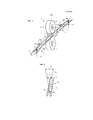
[0028] Фиг. 3 - продольное сечение возможного варианта изобретения.[0028] FIG. 3 is a longitudinal section of a possible embodiment of the invention.
[0029] ПОДРОБНОЕ ОПИСАНИЕ[0029] DETAILED DESCRIPTION
[0030] В варианте по фиг. 1 и 2 система для разрезания на мерные длины длинномерного проката по настоящему изобретению содержит верхний барабан 4 и нижний барабан 6. Каждый барабан 4 или 6 имеет по существу цилиндрическую форму с осью Х или Х' и поддерживает режущее средство, расположенное для одновременного разрезания двух нитей длинномерного проката, приходящего из прокатного стана или другого источника, на готовые сегменты. Оси Х и Х' расположены в одной вертикальной плоскости и проходят параллельно друг другу в этой плоскости.[0030] In the embodiment of FIG. 1 and 2, the system for cutting into measured lengths of long products of the present invention comprises an
[0031] Как показано на фиг. 1-3, режущими средствами могут быть ножи, поддерживаемые барабанами 4 и 6. Каждый нож отходит радиально наружу от внешней стенки соответствующего барабана 4 или 6. В этом варианте каждый барабан 4 или 6 поддерживает пару верхних ножей 8, 8' или пару нижних ноже 10, 10'. В каждой паре ножи выровнены по оси и разнесены друг от друга в осевом направлении, при этом расстояние между ножами зависит от расстояния между двумя нитями изделия. Другими словами, каждый верхний нож 8 и 8' по меньшей мере частично расположен в плоскости, пересекаемой осью Х их барабана 4 и каждый нижний нож 10, 10' по меньшей мере частично расположен в плоскости, пересекаемой осью X' их барабана 6. Кроме того, нижние и верхние ножи разнесены друг от друга про горизонтали в этих плоскостях. И вновь другими словами, ножи 8/8', 10/10' каждого барабана выровнены по линии, параллельной оси этого барабана и разнесены друг от друга по этой линии.[0031] As shown in FIG. 1-3, the cutting means may be knives supported by
[0032] Пары ножей 8/8', 10/10' вращаются вместе с соответствующими барабанами и расположены так, чтобы разделять две нити одновременно, как ножницы. Другими словами, каждый верхний нож 8, 8' взаимодействует с нижним ножом 10, 10' для разрезания нити длинномерного проката на готовые сегменты. В варианте, показанном на чертежах, верхний нож 8 и нижний нож 10, именуемые здесь левыми ножами, предназначены для разрезания одной нити длинномерного проката и расположены по меньшей мере частично в первой радиальной плоскости относительно оси Х, Х'. Таким же образом, верхний нож 8' и нижний нож 10, именуемые здесь правыми ножами, расположены по меньшей мере частично во второй радиальной плоскости относительно оси Х, Х'.[0032] The pairs of
[0033] Правые и левые ножи расположены так, чтобы перекрываться при достижении точки, где их круглые траектории сходятся (например, нижней точки для верхних ножей 8, 8' и верхней точки для нижних ножей 10, 10') так, чтобы разрезать нить 3 или 5 длинномерного проката на готовые сегменты длинномерного проката.[0033] The right and left knives are arranged to overlap when they reach the point where their circular paths converge (for example, the lower point for the
[0034] Барабаны 4, 6 соединены с одним приводным средством или с множеством приводных средств, которое (которые) приводит во вращение эти барабаны с одинаковой скоростью. Как показано на фиг. 3, приводное средство может содержать узел двигателя/редуктора 28.[0034] The
[0035] Система по настоящему изобретению также содержит по меньшей мере две вращающиеся направляющие 12 и 14. Каждая направляющая содержит два канала, и каждый канал предназначен и расположен для приема и направления одной нити длинномерного проката. Как можно видеть на фиг. 1, 2 и 3, входная направляющая 12 проходит горизонтально перед ножницами 7 в направлении движения изделия, а выходная направляющая 14 проходит горизонтально после ножниц 7.[0035] The system of the present invention also comprises at least two
[0036] Каналы 12a/12b или 14f/14b направляющей 12 или 14 могут быть разнесены и соединены друг с другом по меньшей мере одной проставкой 12c или 14c. От каждой из этих проставок 12c или 14c вертикально отходит поворотный стержень (или вал) 12d или 14d. Каждый канал 12a или 12b может содержать входную секцию, имеющую коническую форму, которая ведет в выходную секцию, имеющую постоянное сечение и предназначенную для удержания каждой нити в правильном положении перед разрезанием и после разрезания.[0036] The
[0037] Направляющие 12 и 14 разнесены друг от друга на расстояние, достаточное для взаимодействия ножей для разрезания нитей и, в то же время, для правильного направления нитей и сегмента нитей перед разрезанием и после него.[0037] The
[0038] Как лучше всего видно на фиг. 3, можно применить приводное средство для поворота направляющей вокруг каждого стержня 12d или 14d. Это приводное средство может быть соединено с соединителем 16 или 18, расположенным на [боковой] стороне каждой направляющей 12, 14. В варианте, показанном на фиг. 3, каждое приводное средство содержит узел 20 или 22 кривошипно-шатунного механизма, который приводится в действие двигателем 24 или 26. Каждый узел, включая приводное средство, и направляющая образуют систему шарнирного четырехугольника.[0038] As best seen in FIG. 3, drive means may be used to rotate the guide around each
[0039] Каждый узел 20, 22 при активации циклически поступательно перемещает соответствующую направляющую 12, 14 вперед и назад. Направляющие 12, 14, в свою очередь, поворачиваются вокруг вала 12d или 14d между нерабочим положением, в котором при работе нити длинномеров 2 или 5 расположены не на траектории режущих средств, в положении, где эти нити не могут быть разрезаны, и рабочим положением, в котором две нити 3 и 5 расположены на траектории режущих средств 8, 8' и 10, 10' где нити могут разрезаться режущими средствами на сегменты длинномерного проката. На фиг. 1 и 2 показана конфигурация, в которой нити 3 и 5 находятся вне траектории резания. Движение направляющих 12 и 14 показано на фиг. 2 двойной стрелкой А.[0039] Each
[0040] Для разрезания обеих нитей 3 и 5 на готовые сегменты, барабаны 4 и 6 непрерывно вращаются в противоположных направлениях. Следует отметить, что две нити проката непрерывно движутся вперед с помощью протяжных роликов (не показаны на чертежах), расположенных перед системой и/или после системы по настоящему изобретению.[0040] To cut both
[0041] В варианте, показанном на фиг. 2, приводным средством направляющих управляют на первом этапе так, чтобы в нерабочем положении две нити находились вне траектории режущих средств, при этом одна нить 3 была расположена между левым режущим средством 8 и другой нитью 5, расположенной справа от правого режущего средства 8'. Затем, на втором этапе, обе нити поворачиваются (влево) и устанавливаются на траектории режущего средства и разрезаются на сегменты длинномерного проката. Затем, на третьем этапе обе нити далее поворачиваются влево так, чтобы обе нити 3 и 5 опять оказались вне траектории режущего средства. Это значит, что левая нить 3 находится слева от левого режущего средства 8, а правая нить 5 расположена между двумя режущими средствами. Затем, на четвертом этапе, обе нити возвращают обратно на траекторию режущих средств, и они вновь разрезаются на сегменты длинномерного проката. Затем цикл повторяется с первого этапа.[0041] In the embodiment shown in FIG. 2, the guide means of the guides are controlled in a first step so that in the idle position the two threads are outside the path of the cutting means, with one
[0042] Эти движения показаны двойной стрелкой A, которая показывает направление движения центральной линии CL направляющей 12.[0042] These movements are shown by the double arrow A, which shows the direction of movement of the center line CL of the
[0043] В другом варианте на первом этапе в каждую из направляющих 12 и 14 подают длинномерный прокат с помощью расположенных перед ними протяжных роликов и приводят их в действие так, чтобы установить каждую нить 3 и 5 на круговой траектории правой 8'/10' и левой 8/10 пар ножей. Другими словами, в конце этого оборота каждая нить 3 и 5 соответственно расположена между ножами 8/10 и 8'/10' левой и правой пар ножей.[0043] In another embodiment, in the first step, a lengthy roll is supplied to each of the
[0044] Это движение направляющих показано, например, стрелкой A на фиг. 2.[0044] This movement of the rails is shown, for example, by arrow A in FIG. 2.
[0045] Дальнейшее вращение барабанов 4 и 6 провоцирует наложение ножей 8', 10', образующих правую пару ножей, и наложение ножей 8/10, образующих левую пару ножей, и приводит к одновременному разрезанию обеих нитей 3 и 5.[0045] Further rotation of the
[0046] Одновременно на втором этапе, каждая направляющая 12 и 14 поворачивается в положение, где нити 3 и 4 расположены вне круговой траектории ножей. Например, как можно видеть на фиг. 2, где показан вид сверху устройства по фиг. 1, на котором представлены только ножи 8, 8' или 10, 10', нити повернуты по часовой стрелке до положения, в котором нить 3 находится между ножами 8 и 8' (соответственно 10, 10'), а нить 5 находится слева от ножей 8 и 10'.[0046] At the same time, in the second step, each
[0047] Как описано выше, движение каждой нити 3 и 5 ограничено минимумом, необходимым для отвода каждой нити от положения, в котором каждая нить находится вне траектории двух режущих средств, в положение, в котором каждая нить пересекает траекторию двух режущих средств. Для этого свободное пространство между левым и правым ножами можно использовать для помещения нити 3 или нити 5 вне траекторий резания.[0047] As described above, the movement of each
[0048] Это также позволяет одновременно разрезать обе нити, что упрощает последующие погрузочно-разгрузочные операции с сегментами.[0048] This also allows both threads to be cut simultaneously, which simplifies subsequent loading and unloading operations with segments.
[0049] Затем второй и третий этапы повторяют так, чтобы из обеих нитей одновременно нарезать множества сегментов мерной длины.[0049] Then, the second and third steps are repeated so that multiple segments of measured length are simultaneously cut from both threads.
[0050] Управляющее средство (не показано) синхронизирует различные приводные элементы системы по настоящему изобретению так, чтобы осуществлять резание каждую нить длинномерного проката, например, регулируя частоту вращения двигателей 24 и 26, частоту двигательной части узла 28 мотор-редуктора, и скорости нитей длинномерного проката через частоту вращения протяжных роликов. Положение ножей также может определяться управляющим средством через подходящие датчики, чтобы осуществлять регулировки их положения. Это управляющее средство также управляет вышеуказанными параметрами для получения требуемой длины сегментов длинномерного проката.[0050] A control means (not shown) synchronizes the various drive elements of the system of the present invention so as to cut each strand of long steel, for example, by adjusting the speed of the
[0051] Следует также отметить, что приводное средство может работать так, чтобы обе нити длинномерного проката двигались циклически, с правой стороны режущего средства на левую сторону режущего средства. Это может быть реализовано, например, в варианте, где имеется только один нож на барабане, для резания множества нитей длинномерного проката.[0051] It should also be noted that the drive means can operate so that both strands of lengthy rolling move cyclically from the right side of the cutting means to the left side of the cutting means. This can be implemented, for example, in the embodiment where there is only one knife on the drum, for cutting multiple threads of lengthy rolled products.
[0052] В другом варианте (не показанном на чертежах) каждый барабан имеет только один нож. Каждый нож имеет две режущие поверхности и каждому ножу придана U-образная форма, определяющая проход для одной или более нити. В этом варианте каждый нож может содержать два конца, аналогичных ножам 8 и 8', которые соединены друг с другом проходящим между ними горизонтальным участком. В этом варианте верхний нож имеет перевернутую U-образную форму, а нижний нож - U-образную форму.[0052] In another embodiment (not shown in the drawings), each drum has only one knife. Each knife has two cutting surfaces and each knife is given a U-shape that defines the passage for one or more threads. In this embodiment, each knife may comprise two ends similar to the
[0053] Как было показано выше, согласно настоящему изобретению предлагается эффективное и компактное средство для одновременного разрезания множества нитей, приходящих от стана горячей прокатки.[0053] As shown above, the present invention provides an efficient and compact means for simultaneously cutting multiple threads coming from a hot rolling mill.
Claims (20)
Applications Claiming Priority (3)
| Application Number | Priority Date | Filing Date | Title |
|---|---|---|---|
| EP13425096.8A EP2821153B2 (en) | 2013-07-05 | 2013-07-05 | System for cutting to length long rolled products coming from different strands of a rolling mill |
| EP13425096.8 | 2013-07-05 | ||
| PCT/EP2014/063486 WO2015000779A1 (en) | 2013-07-05 | 2014-06-26 | System and method for cutting to length long rolled products coming from different strands of a rolling mill |
Publications (3)
| Publication Number | Publication Date |
|---|---|
| RU2016103621A RU2016103621A (en) | 2017-08-10 |
| RU2016103621A3 RU2016103621A3 (en) | 2018-03-29 |
| RU2655871C2 true RU2655871C2 (en) | 2018-05-29 |
Family
ID=49226103
Family Applications (1)
| Application Number | Title | Priority Date | Filing Date |
|---|---|---|---|
| RU2016103621A RU2655871C2 (en) | 2013-07-05 | 2014-06-26 | System and method for cutting to length long rolled products coming from different strands of rolling mill |
Country Status (9)
| Country | Link |
|---|---|
| US (1) | US10994348B2 (en) |
| EP (1) | EP2821153B2 (en) |
| JP (1) | JP6158438B2 (en) |
| CN (1) | CN105377457B (en) |
| BR (1) | BR112015033007B1 (en) |
| ES (1) | ES2649415T3 (en) |
| PL (1) | PL2821153T3 (en) |
| RU (1) | RU2655871C2 (en) |
| WO (1) | WO2015000779A1 (en) |
Families Citing this family (2)
| Publication number | Priority date | Publication date | Assignee | Title |
|---|---|---|---|---|
| ITMI20130107A1 (en) * | 2013-01-24 | 2014-07-25 | Danieli Off Mecc | CONVEYING DEVICE FOR LAMINATED BARS OUTPUT FROM A CUTTING SHEAR, ITS CUTTING MACHINE AND ITS CUTTING PROCESS |
| ITMI20131670A1 (en) * | 2013-10-09 | 2015-04-10 | Danieli Off Mecc | SINGLE SHEAR FOR CUTTING AND CONVEYING MORE LAMINATES |
Citations (3)
| Publication number | Priority date | Publication date | Assignee | Title |
|---|---|---|---|---|
| SU740418A1 (en) * | 1978-02-15 | 1980-06-15 | Украинский научно-исследовательский институт металлов | Drum-type flying shears |
| SU1407704A1 (en) * | 1987-01-04 | 1988-07-07 | Всесоюзный научно-исследовательский и проектно-конструкторский институт металлургического машиностроения им.А.И.Целикова | Arrangement for flying shears for guiding the movement of cut-off pieces of rolled stock |
| US20050235721A1 (en) * | 2004-04-21 | 2005-10-27 | Shore T M | Divide and chop shear arrangement |
Family Cites Families (35)
| Publication number | Priority date | Publication date | Assignee | Title |
|---|---|---|---|---|
| US2126528A (en) * | 1937-03-09 | 1938-08-09 | Phelps Dodge Copper Prod | Apparatus for continuous wire drawing |
| US2234976A (en) * | 1940-01-15 | 1941-03-18 | Wire Sales Company | Wire cutting machine |
| US2414772A (en) * | 1944-10-11 | 1947-01-21 | Morgan Construction Co | Shearing apparatus |
| US2701016A (en) * | 1949-05-31 | 1955-02-01 | Blaw Knox Co | Rotary flying shear mechanism for rod rolling mills or the like |
| US2924136A (en) | 1956-08-13 | 1960-02-09 | Birdsboro Steel Foundry & Mach | Flying shear |
| FR2120160B1 (en) * | 1970-12-31 | 1973-06-08 | Kawasaki Heavy Ind Ltd | |
| DE2132124C3 (en) * | 1971-06-28 | 1975-05-28 | Danieli & C. S.P.A., Buttrio, Udine (Italien) | Rotating shears, especially for rolling stock that is sniffing |
| SU656265A2 (en) | 1972-11-09 | 1989-07-15 | Минский Радиозавод Им.50-Летия Компартии Белоруссии | Injection mould |
| US3834260A (en) | 1973-07-02 | 1974-09-10 | Morgan Construction Co | Switching mechanism for cropping and sampling front and back ends of bar product delivered from mill |
| IT1051128B (en) | 1975-10-13 | 1981-04-21 | Simac Spa | HIGH SPEED CUTTING FLYING SHEARS WITH PARALLEL OPERATING GROUPS E.O IN COMBINED AND RALATIVE SERIES CUTTING SYSTEM |
| JPS53105780A (en) | 1977-02-28 | 1978-09-14 | Nippon Steel Corp | Shearing apparatus |
| JPS5824209B2 (en) | 1978-07-13 | 1983-05-19 | 株式会社神戸製鋼所 | High-speed wire cutting device |
| US4392399A (en) * | 1981-05-21 | 1983-07-12 | Veb Schwermaschinen-Kombinat "Ernst Thalmann" Magdeburg | Drum-type wire shear |
| US4406198A (en) * | 1981-05-21 | 1983-09-27 | Veb Schwermaschinenbau-Kombinat "Ernst Thalmann" Magdeburg | Drum-type wire shear |
| IT1181157B (en) | 1984-01-27 | 1987-09-23 | Danieli Off Mecc | COMPACT SHEAR WITH SCRAPER |
| JPH0240450B2 (en) | 1986-02-25 | 1990-09-11 | Kobe Steel Ltd | FURAINGUSHAASOCHI |
| DD258378B5 (en) | 1987-03-13 | 1997-03-20 | Sket Schwermamaschinenbau Gmbh | Process for the continuous production of steel rod finishing lengths |
| IT1214195B (en) | 1987-06-30 | 1990-01-10 | Danieli Off Mecc | HIGH SPEED FLYING SHEAR. |
| IT1220109B (en) * | 1987-07-13 | 1990-06-06 | Danieli Off Mecc | TAIL HEAD POINTING SYSTEM WITH SAMPLING |
| US5040440A (en) * | 1990-05-09 | 1991-08-20 | Stelco, Inc. | Product switching mechanism |
| DE4101941C2 (en) | 1991-01-21 | 1993-11-18 | Mannesmann Ag | Cold forming of wires |
| JPH069816A (en) | 1992-06-25 | 1994-01-18 | Matsushita Refrig Co Ltd | Foamed heat insulating material and heat insulating box material |
| JPH069816U (en) | 1992-07-10 | 1994-02-08 | 株式会社神戸製鋼所 | Split shear for multi-roll rolling |
| JPH07124814A (en) | 1993-10-28 | 1995-05-16 | Kobe Steel Ltd | Cutting method for rolled filament material and equipment therefor |
| IT1262245B (en) * | 1993-11-30 | 1996-06-19 | Danieli Off Mecc | HIGH SPEED FLYING SHEAR |
| US5526726A (en) * | 1993-12-23 | 1996-06-18 | Morgan Construction Company | High speed shear for end trimming rods and the like |
| DE19611302A1 (en) | 1996-03-22 | 1997-09-25 | Schloemann Siemag Ag | Method and device for separating and draining front and / or rear shoops on running rolling stock |
| DE19738470A1 (en) * | 1997-09-03 | 1999-03-11 | Sket Walzwerkstechnik Gmbh | Device for scooping and deflecting a roller core |
| DE19746528A1 (en) | 1997-10-22 | 1999-04-29 | Schloemann Siemag Ag | High-speed shears for cross cutting of rolled strip |
| US6745656B1 (en) * | 1999-04-08 | 2004-06-08 | Morgan Construction Company | High speed flying shear |
| DE10057716A1 (en) | 2000-11-15 | 2002-05-23 | Sms Demag Ag | Rotating shears used for cropping quickly moving rolled material, especially wire, have a guiding part as a lifting and lowering three-compartment guide at the rear |
| CH698243B1 (en) | 2005-07-27 | 2009-06-30 | Mtag Marti Technologie Ag | A method for cutting or cropping of a at a rolling speed moving rolling and scissors for performing the method. |
| US20120198978A1 (en) * | 2011-02-07 | 2012-08-09 | Siemens Industry, Inc. | Shearing system for moving product |
| ITMI20130107A1 (en) * | 2013-01-24 | 2014-07-25 | Danieli Off Mecc | CONVEYING DEVICE FOR LAMINATED BARS OUTPUT FROM A CUTTING SHEAR, ITS CUTTING MACHINE AND ITS CUTTING PROCESS |
| US9278456B2 (en) * | 2013-06-20 | 2016-03-08 | Siemens Industry, Inc. | High speed traversing shear |
-
2013
- 2013-07-05 ES ES13425096.8T patent/ES2649415T3/en active Active
- 2013-07-05 EP EP13425096.8A patent/EP2821153B2/en active Active
- 2013-07-05 PL PL13425096T patent/PL2821153T3/en unknown
-
2014
- 2014-06-26 BR BR112015033007-0A patent/BR112015033007B1/en active IP Right Grant
- 2014-06-26 JP JP2016522491A patent/JP6158438B2/en active Active
- 2014-06-26 WO PCT/EP2014/063486 patent/WO2015000779A1/en active Application Filing
- 2014-06-26 CN CN201480038243.2A patent/CN105377457B/en active Active
- 2014-06-26 RU RU2016103621A patent/RU2655871C2/en active
- 2014-06-26 US US14/902,988 patent/US10994348B2/en active Active
Patent Citations (3)
| Publication number | Priority date | Publication date | Assignee | Title |
|---|---|---|---|---|
| SU740418A1 (en) * | 1978-02-15 | 1980-06-15 | Украинский научно-исследовательский институт металлов | Drum-type flying shears |
| SU1407704A1 (en) * | 1987-01-04 | 1988-07-07 | Всесоюзный научно-исследовательский и проектно-конструкторский институт металлургического машиностроения им.А.И.Целикова | Arrangement for flying shears for guiding the movement of cut-off pieces of rolled stock |
| US20050235721A1 (en) * | 2004-04-21 | 2005-10-27 | Shore T M | Divide and chop shear arrangement |
Also Published As
| Publication number | Publication date |
|---|---|
| BR112015033007A2 (en) | 2017-07-25 |
| WO2015000779A1 (en) | 2015-01-08 |
| ES2649415T3 (en) | 2018-01-11 |
| US20160151815A1 (en) | 2016-06-02 |
| CN105377457B (en) | 2018-05-15 |
| EP2821153A1 (en) | 2015-01-07 |
| RU2016103621A (en) | 2017-08-10 |
| CN105377457A (en) | 2016-03-02 |
| PL2821153T3 (en) | 2018-02-28 |
| JP6158438B2 (en) | 2017-07-05 |
| EP2821153B1 (en) | 2017-08-30 |
| US10994348B2 (en) | 2021-05-04 |
| BR112015033007B1 (en) | 2023-03-07 |
| EP2821153B2 (en) | 2024-01-24 |
| RU2016103621A3 (en) | 2018-03-29 |
| JP2016529105A (en) | 2016-09-23 |
Similar Documents
| Publication | Publication Date | Title |
|---|---|---|
| TWI474910B (en) | Method and apparatus for producing cut to length bars in a steel mill | |
| CN101505930B (en) | Machine for cutting paper logs | |
| RU2655871C2 (en) | System and method for cutting to length long rolled products coming from different strands of rolling mill | |
| US20150298331A1 (en) | Method and apparatus for supporting product during cutting | |
| RU2367534C1 (en) | System for reception and transportation of feed bars from rolling mill to storage-discharge facility | |
| US20210086385A1 (en) | Cutting machine for cutting elongated products, and related method | |
| EP2948263B1 (en) | Conveying device of rolled bars exiting from a cutting shear, cutting machine and cutting process thereof | |
| RU2298446C2 (en) | Method and apparatus for subdividing hot rolled article cut pieces fed from rolling mill | |
| JP6199488B2 (en) | Drum, system and method for processing long rolled products conveyed from different strands of a rolling mill | |
| JP2004188499A (en) | Rod delivery system and method | |
| US3422652A (en) | Method and machine for changing the curvature of elongated workpieces | |
| KR0138471B1 (en) | High speed shear for end trimming rods and the like | |
| DE602005004668T2 (en) | STABPACKUNGSANLAGE AND CORRESPONDING METHOD | |
| US2726754A (en) | Rotary kickoff for cooling bed | |
| EP0685274B1 (en) | Method and device for severing and controlled cooling of single bars from a rolled section | |
| CN110383410A (en) | Machining apparatus and method | |
| WO2004080624A1 (en) | Device for extruding curved extruded profiles | |
| JP7163225B2 (en) | Rolling method and rolling equipment | |
| JPH07124814A (en) | Cutting method for rolled filament material and equipment therefor | |
| KR20180132754A (en) | Method for manufacturing cold-filler mill and pipe | |
| US20140041432A1 (en) | Hot-rolling machine for wire-rod and the like | |
| EP0290710A1 (en) | Reversing rolling mill for producing steel rods | |
| JPH10156421A (en) | Manufacture of pointed wire | |
| NO153925B (en) | DEVICE BY PUNCH BOATS. |