RU2653382C2 - Hydraulic press - Google Patents
Hydraulic press Download PDFInfo
- Publication number
- RU2653382C2 RU2653382C2 RU2016126048A RU2016126048A RU2653382C2 RU 2653382 C2 RU2653382 C2 RU 2653382C2 RU 2016126048 A RU2016126048 A RU 2016126048A RU 2016126048 A RU2016126048 A RU 2016126048A RU 2653382 C2 RU2653382 C2 RU 2653382C2
- Authority
- RU
- Russia
- Prior art keywords
- cylinders
- cross member
- hydraulic
- power element
- hydraulic press
- Prior art date
Links
- 230000013011 mating Effects 0.000 claims description 2
- 239000002184 metal Substances 0.000 abstract description 5
- 239000000126 substance Substances 0.000 abstract 1
- 238000003825 pressing Methods 0.000 description 3
- 229910000831 Steel Inorganic materials 0.000 description 1
- 239000002131 composite material Substances 0.000 description 1
- 238000010276 construction Methods 0.000 description 1
- 238000005265 energy consumption Methods 0.000 description 1
- 239000012530 fluid Substances 0.000 description 1
- 238000005242 forging Methods 0.000 description 1
- 238000012423 maintenance Methods 0.000 description 1
- 238000004519 manufacturing process Methods 0.000 description 1
- 238000000034 method Methods 0.000 description 1
- 230000001681 protective effect Effects 0.000 description 1
- 230000000284 resting effect Effects 0.000 description 1
- 239000010959 steel Substances 0.000 description 1
Images

Classifications
-
- B—PERFORMING OPERATIONS; TRANSPORTING
- B30—PRESSES
- B30B—PRESSES IN GENERAL
- B30B1/00—Presses, using a press ram, characterised by the features of the drive therefor, pressure being transmitted directly, or through simple thrust or tension members only, to the press ram or platen
- B30B1/32—Presses, using a press ram, characterised by the features of the drive therefor, pressure being transmitted directly, or through simple thrust or tension members only, to the press ram or platen by plungers under fluid pressure
-
- B—PERFORMING OPERATIONS; TRANSPORTING
- B30—PRESSES
- B30B—PRESSES IN GENERAL
- B30B15/00—Details of, or accessories for, presses; Auxiliary measures in connection with pressing
- B30B15/04—Frames; Guides
Landscapes
- Engineering & Computer Science (AREA)
- Mechanical Engineering (AREA)
- Physics & Mathematics (AREA)
- Fluid Mechanics (AREA)
- Press Drives And Press Lines (AREA)
- Presses And Accessory Devices Thereof (AREA)
Abstract
Description
Изобретение относится к области машиностроения, в частности к созданию или модернизации гидравлических прессов различного назначения.The invention relates to the field of engineering, in particular to the creation or modernization of hydraulic presses for various purposes.
По патенту RU 2281204 известен вертикальный гидравлический пресс, содержащий верхнюю поперечину и станину, стянутые колоннами, по которым направляется подвижная траверса с верхним инструментом, установленную на станине промежуточную плиту с выдвижным столом, закрепленным на нем нижним инструментом, где станина снабжена со стороны нижней поверхности гидроцилиндрами и вертикальными стяжками, в промежуточной плите на боковых поверхностях предусмотрены цапфы, жестко скрепленные с промежуточной плитой, например, путем запрессовки их концов, при этом цапфы и станина выполнены с отверстиями, через которые проходят вертикальные стяжки, на верхних концах последних выполнены головки, опирающиеся на цапфы, а нижние концы стяжек соединены посредством гаек с гидроцилиндрами, плунжеры которых через сферические шайбы опираются на нижнюю поверхность станины, гидроцилиндры запитаны постоянным давлением жидкости от гидропривода пресса.According to patent RU 2281204, a vertical hydraulic press is known, comprising an upper cross member and a bed, tightened by columns, along which a movable beam is guided with an upper tool, an intermediate plate mounted on the bed with a sliding table fixed to it with a lower tool, where the bed is provided with hydraulic cylinders on the lower surface side and vertical ties, in the intermediate plate on the side surfaces, trunnions are provided that are rigidly fastened to the intermediate plate, for example, by pressing in their ends, In this case, the pins and bed are made with holes through which vertical couplers pass, at the upper ends of the latter there are made heads resting on the pins, and the lower ends of the couplers are connected by means of nuts with hydraulic cylinders, the plungers of which are supported through the spherical washers on the lower surface of the bed, the hydraulic cylinders are fed with a constant fluid pressure from the hydraulic press.
Недостатками известного пресса являются сложность и высокая металлоемкость конструкции.The disadvantages of the known press are the complexity and high metal construction.
Наиболее близким к заявленному техническому решению является известный по патенту RU 111803 гидравлический ковочный пресс, содержащий станину, выполненную в виде верхней и нижней неподвижных поперечин, стянутых колоннами, подвижную поперечину, расположенную с возможностью перемещения по колоннам, рабочие и возвратные цилиндры, размещенные со стороны верхней неподвижной поперечины, завесы для защиты колонн, где завесы выполнены в виде сплошных защитных кожухов из композиционного материала, прикрепленных непосредственно к подвижной поперечине.Closest to the claimed technical solution is the hydraulic forging press known according to the patent RU 111803, comprising a bed made in the form of an upper and lower fixed cross-member, pulled together by columns, a movable cross-member located to move along the columns, working and return cylinders placed on the upper side a fixed cross member, curtains for protecting columns, where the curtains are made in the form of continuous protective casings of composite material attached directly to the movable cross the city.
Недостатками известного пресса являются сложность и высокая металлоемкость конструкции, низкая ремонтопригодность.The disadvantages of the known press are the complexity and high metal consumption of the structure, low maintainability.
Техническим результатом заявленного изобретения является снижение габаритов и металлоемкости, упрощение конструкции вследствие использования более простых и доступных узлов, повышение ремонтопригодности.The technical result of the claimed invention is to reduce the dimensions and metal consumption, simplify the design due to the use of simpler and more affordable nodes, increase maintainability.
Технический результат достигается тем, что в гидравлическом прессе, содержащем станину колонного типа с верхней и нижней поперечинами и траверсу со штампом, установленную с возможностью перемещения под действием рабочих цилиндров, согласно изобретению верхняя поперечина состоит из силового элемента, выполненного обеспечивающим стягивание станины, внизу которой расположены рабочие цилиндры, и подвижного сегмента, установленного с возможностью перемещения относительно силового элемента под действием закрепленных на нижней поперечине станины цилиндров быстрого хода и фиксации относительно упомянутого силового элемента посредством механизма фиксации.The technical result is achieved by the fact that in a hydraulic press containing a column-type bed with upper and lower cross-beams and a crosshead with a stamp, mounted for movement under the action of working cylinders, according to the invention, the upper cross-member consists of a power element made to tighten the bed, below which are located working cylinders, and a movable segment mounted to move relative to the power element under the action of fixed on the lower cross th frame rapid traverse cylinder and with respect to said fixing means fixing the actuator mechanism.
Механизм фиксации выполнен состоящим из по меньшей мере двух балок, установленных в гнездах, выполненных в силовом элементе или подвижном сегменте верхней поперечины, с возможностью перемещения под действием гидроцилиндров и расположения в ответных отверстиях, выполненных соответственно в подвижном сегменте или силовом элементе.The locking mechanism is made up of at least two beams installed in sockets made in the power element or the movable segment of the upper cross member, with the possibility of movement under the action of hydraulic cylinders and location in the mating holes made respectively in the movable segment or power element.
Размещение подвижного сегмента верхней поперечины на цилиндрах быстрого хода, закрепленных на нижней поперечине, позволяет выполнить верхнюю поперечину составной, что позволяет производить раскрытие рабочего пространства для подачи заготовки без использования собственного хода траверсы со штампом, что дает возможность не перемещать рабочие цилиндры на быстром ходу. Это существенно сокращает общий ход рабочих цилиндров, что позволяет значительно сократить их размеры. При этом появляется возможность использовать простые и легкодоступные гидроцилиндры домкратов, которые выпускаются серийно, что значительно упрощает конструкцию, поскольку рабочие цилиндры являются самой сложной в изготовлении и металлоемкой частью гидравлического пресса. Использование в качестве рабочих цилиндров гидроцилиндров домкратов позволяет легко производить их замену в случае поломки, что повышает ремонтопригодность изделия. Кроме того, появляется возможность существенно сократить длину колонн или рамы, поскольку траверса не перемещается по ним на быстром ходу. Таким образом, заявленная совокупность существенных признаков изобретения позволяет упростить конструкцию и снизить ее металлоемкость. При этом наличие механизма фиксации-дефиксации элементов верхней поперечины относительно друг друга позволяет жестко соединять их во время совершения рабочей операции. Для надежной фиксации использован механизм фиксации-дефиксации, включающий по меньшей мере две подвижные балки, приводимые в движение гидроцилиндрами и установленные в гнезда в корпусе подвижного сегмента или силового элемента верхней поперечины, при этом в корпусе силового элемента или подвижного сегмента верхней поперечины выполнены отверстия, ответные вышеуказанным балкам. Такая конструкция механизма позволяет осуществлять процесс фиксации-дефиксации автоматически, например, посредством подключения цилиндров быстрого хода и механизма фиксации-дефиксации к одному контуру низкого давления.Placing the movable segment of the upper cross member on the high-speed cylinders mounted on the lower cross-member allows the upper cross-member to be made integral, which allows opening the working space for feeding the workpiece without using the traverse’s own stroke with a stamp, which makes it possible not to move the working cylinders in high speed. This significantly reduces the overall stroke of the working cylinders, which can significantly reduce their size. In this case, it becomes possible to use simple and easily accessible jack cylinders, which are mass-produced, which greatly simplifies the design, since the working cylinders are the most difficult to manufacture and metal-intensive part of the hydraulic press. The use of jacks as hydraulic cylinders makes it easy to replace them in case of breakage, which increases the maintainability of the product. In addition, it becomes possible to significantly reduce the length of the columns or frame, since the beam does not move along them at high speed. Thus, the claimed combination of essential features of the invention allows to simplify the design and reduce its metal consumption. Moreover, the presence of a mechanism of fixation-fixation of the elements of the upper cross member relative to each other allows you to rigidly connect them during the work operation. For reliable fixation, a fixation-fixation mechanism is used, which includes at least two movable beams driven by hydraulic cylinders and installed in sockets in the housing of the movable segment or power element of the upper cross member, while holes in the body of the power element or mobile segment of the upper cross member are made the above beams. Such a design of the mechanism allows the fixing-fixing process to be carried out automatically, for example, by connecting the high-speed cylinders and the locking-fixing mechanism to one low pressure circuit.
Экспериментальная установка была собрана на базе рамы от штамповочного пресса ДЕ2430 усилием 100 тонн производства Нелидовского завода гидравлических прессов. В качестве рабочего цилиндра использовался доработанный домкрат ДГ100П100 производства Энерпром. В качестве цилиндров быстрого хода использовались гидроцилиндры ГЦ 100.50×400 производства Елецгидроагрегат. Гидравлический пресс использовался для штамповки из стальной тонкостенной заготовки. В ходе испытаний гидравлический пресс подтвердил функциональную идентичность прототипу при меньших размерах рабочего цилиндра.The experimental setup was assembled on the basis of a frame from a stamping press DE2430 with an effort of 100 tons produced by the Nelidovo plant of hydraulic presses. As a working cylinder, a modified jack DG100P100 manufactured by Enerprom was used. Hydraulic cylinders GC 100.50 × 400 manufactured by Eletshydroagregat were used as high-speed cylinders. A hydraulic press was used for stamping from a steel thin-walled workpiece. During the tests, the hydraulic press confirmed the functional identity of the prototype with a smaller working cylinder.
Например, гидроцилиндр домкрата с усилием 150 тонн и ходом в 100 мм весит всего 52 кг. Следовательно, при появлении утечки через шток на гидравлическом прессе, с использованием таких цилиндров, появляется возможность заменить цилиндр полностью, а потом заниматься заменой манжет в условиях специализированной мастерской. Кроме того, так как рабочие цилиндры расположены снизу, это исключает попадание этих утечек в рабочую зону гидравлического пресса, что обеспечивает повышение безопасности работы оператора и снижение процента брака, особенно при работе с горячими заготовками. Для демонтажа силовых цилиндров из основания гидравлического пресса можно воспользоваться цилиндрами быстрого хода, для этого при расчете параметров цилиндра нужно добавить к их целевой нагрузке вес силового цилиндра. Это позволит существенно сократить простои по этому виду технического обслуживания. Так как при осуществлении быстрых ходов масло нужно подавать только в цилиндры быстрого хода, нет необходимости в использовании баков наполнения и клапанов наполнения, что тоже существенно снижает стоимость и габариты. Использование в контуре низкого давления насосов с пропорциональным регулированием рабочего объема позволит снизить энергопотребление гидравлического пресса, осуществлять эффективную синхронизацию на быстром ходу и реализовать работу с высокой скоростью быстрого хода и плавным торможением в крайних точках. Это улучшит показатели производительности. Предполагается оснащать гидравлические прессы, при желании заказчика, встроенными устройствами для быстрой переналадки - шариковыми гидравлическими направляющими и гидравлическими зажимами штампов. Это позволит снизить простои на переналадку и увеличить производительность.For example, a jack hydraulic cylinder with a force of 150 tons and a stroke of 100 mm weighs only 52 kg. Therefore, when a leak occurs through the rod on a hydraulic press, using such cylinders, it becomes possible to replace the cylinder completely, and then engage in cuff replacement in a specialized workshop. In addition, since the working cylinders are located at the bottom, this prevents these leaks from entering the working area of the hydraulic press, which improves operator safety and reduces the percentage of rejects, especially when working with hot workpieces. To dismantle the power cylinders from the base of the hydraulic press, you can use high-speed cylinders; for this, when calculating the cylinder parameters, the weight of the power cylinder must be added to their target load. This will significantly reduce downtime for this type of maintenance. Since the oil must be supplied only to the high-speed cylinders when carrying out high-speed strokes, there is no need to use filling tanks and filling valves, which also significantly reduces the cost and dimensions. The use of pumps with proportional control of the working volume in the low pressure circuit will reduce the energy consumption of the hydraulic press, carry out efficient synchronization at high speed and realize work with high speed high speed and smooth braking at extreme points. This will improve performance. It is supposed to equip hydraulic presses, if the customer so desires, with built-in devices for quick readjustment - ball hydraulic guides and hydraulic die clamps. This will reduce downgrade downtime and increase productivity.
Сущность заявленного технического решения поясняется рисунками, на которых изображен вариант исполнения гидравлического пресса со станиной, стянутой колоннами:The essence of the claimed technical solution is illustrated by drawings, which depict an embodiment of a hydraulic press with a bed, pulled together by columns:
На фиг. 1 изображен вид спереди на гидравлический пресс с опущенным подвижным сегментом.In FIG. 1 is a front view of a hydraulic press with a movable segment lowered.
На фиг. 2 изображен вид спереди на гидравлический пресс с поднятым подвижным сегментом.In FIG. 2 is a front view of a hydraulic press with a raised movable segment.
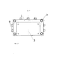
На фиг. 3 изображен вид на гидравлический пресс сверху.In FIG. 3 shows a top view of a hydraulic press.
Гидравлический пресс содержит верхнюю поперечину, состоящую из силового элемента 1, стягивающего конструкцию, и совмещаемого с ним подвижного сегмента 2, колонны 3, цилиндры быстрого хода 4, силовые цилиндры 5, траверсу 6 со штампом 7, нижнюю поперечину 8, механизм фиксации-дефиксации 9.The hydraulic press contains an upper cross member, consisting of a
Рабочий цикл гидравлического пресса происходит следующим образом.The duty cycle of the hydraulic press is as follows.
1. Начальное положение. В начале цикла подвижный сегмент верхней поперечины поднят.1. Starting position. At the beginning of the cycle, the movable segment of the upper cross member is raised.
2. Быстрый ход. Подвижный сегмент верхней поперечины посредством цилиндров быстрого хода перемещается на уровень силового элемента верхней поперечины.2. High speed. The movable segment of the upper cross member by means of high speed cylinders moves to the level of the power element of the upper cross member.
3. Фиксация. По окончании быстрого хода подвижный сегмент верхней поперечины фиксируется относительно силового элемента верхней поперечины с помощью гидроцилиндров фиксаторов.3. Fixation. At the end of the fast stroke, the movable segment of the upper cross member is fixed relative to the power element of the upper cross member using the clamp hydraulic cylinders.
4. Рабочий ход. Начинают работу рабочие цилиндры. Сначала в них подается масло из обоих контуров - низкого и высокого давления. После того как давление достигает уровня настройки реле низкого давления, контур низкого давления разгружается и в работе остается только контур высокого давления. Происходит прессование.4. The working stroke. Work cylinders begin to work. First, oil is supplied to them from both circuits - low and high pressure. After the pressure reaches the setting level of the low pressure switch, the low pressure circuit is unloaded and only the high pressure circuit remains in operation. Pressing occurs.
5. Дефиксация. После того как прессование и необходимая выдержка времени окончены, происходит сброс давления с силовых цилиндров. По окончании сброса давления цилиндры фиксаторов разблокируют подвижный сегмент верхней поперечины относительно силового элемента верхней поперечины.5. Fixation. After pressing and the necessary time delay are over, pressure is released from the power cylinders. At the end of the pressure relief, the retainer cylinders unlock the movable segment of the upper cross member relative to the power element of the upper cross member.
6. Обратный ход силовых цилиндров осуществляется под собственным весом траверсы и штампа (или, при необходимости, с помощью цилиндров быстрого хода, для этого нужно будет их выполнить поршневыми, а не плунжерными) и одновременно с быстрым обратным ходом. Быстрый обратный ход осуществляется цилиндрами быстрого хода.6. The return stroke of the power cylinders is carried out under the deadweight of the traverse and stamp (or, if necessary, using high-speed cylinders, for this it will be necessary to perform them piston, not plunger) and at the same time with a quick reverse stroke. Fast reverse is carried out by high speed cylinders.
7. Конец цикла. Подвижный сегмент верхней поперечины возвращается в начальное положение. Цикл закончен.7. The end of the cycle. The movable segment of the upper cross member returns to its initial position. The cycle is over.
Claims (2)
Priority Applications (1)
| Application Number | Priority Date | Filing Date | Title |
|---|---|---|---|
| RU2016126048A RU2653382C2 (en) | 2016-06-28 | 2016-06-28 | Hydraulic press |
Applications Claiming Priority (1)
| Application Number | Priority Date | Filing Date | Title |
|---|---|---|---|
| RU2016126048A RU2653382C2 (en) | 2016-06-28 | 2016-06-28 | Hydraulic press |
Publications (2)
| Publication Number | Publication Date |
|---|---|
| RU2016126048A RU2016126048A (en) | 2018-01-10 |
| RU2653382C2 true RU2653382C2 (en) | 2018-05-08 |
Family
ID=60965241
Family Applications (1)
| Application Number | Title | Priority Date | Filing Date |
|---|---|---|---|
| RU2016126048A RU2653382C2 (en) | 2016-06-28 | 2016-06-28 | Hydraulic press |
Country Status (1)
| Country | Link |
|---|---|
| RU (1) | RU2653382C2 (en) |
Citations (5)
| Publication number | Priority date | Publication date | Assignee | Title |
|---|---|---|---|---|
| SU432005A1 (en) * | 1973-01-17 | 1974-06-15 | HYDRAULIC PRESS | |
| SU867657A1 (en) * | 1979-07-18 | 1981-09-30 | Научно-Исследовательский Институт Тяжелого Машиностроения Производственного Объединения "Уралмаш" | Vertical hydraulic press |
| US4690049A (en) * | 1985-11-12 | 1987-09-01 | John T. Hepburn, Limited | Hydraulic press with side slab guided upper platen |
| WO2005097480A1 (en) * | 2004-04-07 | 2005-10-20 | Sinterteknik I Husqvarna Hubbe Ab | A hydraulic press with a displacable platen |
| RU111803U1 (en) * | 2011-07-08 | 2011-12-27 | Открытое акционерное общество "Магнитогорский металлургический комбинат" | HYDRAULIC FORGING PRESS |
-
2016
- 2016-06-28 RU RU2016126048A patent/RU2653382C2/en not_active IP Right Cessation
Patent Citations (5)
| Publication number | Priority date | Publication date | Assignee | Title |
|---|---|---|---|---|
| SU432005A1 (en) * | 1973-01-17 | 1974-06-15 | HYDRAULIC PRESS | |
| SU867657A1 (en) * | 1979-07-18 | 1981-09-30 | Научно-Исследовательский Институт Тяжелого Машиностроения Производственного Объединения "Уралмаш" | Vertical hydraulic press |
| US4690049A (en) * | 1985-11-12 | 1987-09-01 | John T. Hepburn, Limited | Hydraulic press with side slab guided upper platen |
| WO2005097480A1 (en) * | 2004-04-07 | 2005-10-20 | Sinterteknik I Husqvarna Hubbe Ab | A hydraulic press with a displacable platen |
| RU111803U1 (en) * | 2011-07-08 | 2011-12-27 | Открытое акционерное общество "Магнитогорский металлургический комбинат" | HYDRAULIC FORGING PRESS |
Also Published As
| Publication number | Publication date |
|---|---|
| RU2016126048A (en) | 2018-01-10 |
Similar Documents
| Publication | Publication Date | Title |
|---|---|---|
| US6240818B1 (en) | Precision blanking press with knife-edged ring and counter cylinder | |
| US3158046A (en) | Hydraulic forging press | |
| US7806031B1 (en) | Device for finely cutting workpieces from a material | |
| US4419878A (en) | Hydraulic drop forging press of above-construction with prestressed press frame | |
| CN106583567A (en) | Anti-deformation machining die | |
| US4024807A (en) | Press | |
| US3465669A (en) | Guide for the slide of a vertical press | |
| RU2653382C2 (en) | Hydraulic press | |
| RU195037U1 (en) | Hydraulic horizontal press | |
| CN111889604A (en) | High-precision forging and pressing equipment | |
| US4372144A (en) | Wrap ring assembly for precision no-draft forging | |
| CN203779911U (en) | Workbench follow-up device for single-pole quenching hydraulic press | |
| JPH05248405A (en) | Pressurizer of working machine | |
| US3681958A (en) | High pressure forming press | |
| EP3194088A1 (en) | Press brakes | |
| CN109249636A (en) | A kind of height-adjustable Manual hydraulic press | |
| US2944320A (en) | Equipment for forging the cranks of crankshafts in consecutive operations | |
| US2428620A (en) | Press structure | |
| RU2080996C1 (en) | Hydraulic forging press | |
| RU2281204C2 (en) | Vertical hydraulic press | |
| US3304823A (en) | Method and apparatus for punching sheet material | |
| JPS63213B2 (en) | ||
| US3777539A (en) | Forging press | |
| RU2352428C2 (en) | Multiple-head forging facility | |
| SU1081003A1 (en) | Deep-drawing hydraulic press |
Legal Events
| Date | Code | Title | Description |
|---|---|---|---|
| MM4A | The patent is invalid due to non-payment of fees |
Effective date: 20190629 |