RU2648503C1 - Unmanned convertiplane with an arched wing - Google Patents
Unmanned convertiplane with an arched wing Download PDFInfo
- Publication number
- RU2648503C1 RU2648503C1 RU2017100220A RU2017100220A RU2648503C1 RU 2648503 C1 RU2648503 C1 RU 2648503C1 RU 2017100220 A RU2017100220 A RU 2017100220A RU 2017100220 A RU2017100220 A RU 2017100220A RU 2648503 C1 RU2648503 C1 RU 2648503C1
- Authority
- RU
- Russia
- Prior art keywords
- wing
- screws
- semicircular
- arched
- along
- Prior art date
Links
- 230000005540 biological transmission Effects 0.000 claims abstract description 17
- 239000003638 chemical reducing agent Substances 0.000 claims abstract description 7
- 239000003351 stiffener Substances 0.000 claims abstract description 7
- 210000002480 semicircular canal Anatomy 0.000 claims description 11
- 230000002441 reversible effect Effects 0.000 claims description 8
- 238000005516 engineering process Methods 0.000 claims description 7
- 230000003068 static effect Effects 0.000 claims description 5
- 230000001360 synchronised effect Effects 0.000 claims description 4
- 230000015556 catabolic process Effects 0.000 claims description 3
- 238000006731 degradation reaction Methods 0.000 claims description 3
- 230000008014 freezing Effects 0.000 claims description 3
- 238000007710 freezing Methods 0.000 claims description 3
- 238000009434 installation Methods 0.000 claims description 2
- 230000007704 transition Effects 0.000 claims description 2
- 238000002507 cathodic stripping potentiometry Methods 0.000 claims 2
- 238000006243 chemical reaction Methods 0.000 claims 1
- 230000001052 transient effect Effects 0.000 abstract description 2
- 230000000694 effects Effects 0.000 abstract 1
- 239000000126 substance Substances 0.000 abstract 1
- 208000029108 46,XY sex reversal 8 Diseases 0.000 description 8
- 238000007664 blowing Methods 0.000 description 3
- 239000003381 stabilizer Substances 0.000 description 3
- 239000006096 absorbing agent Substances 0.000 description 2
- 239000000446 fuel Substances 0.000 description 2
- 238000004519 manufacturing process Methods 0.000 description 2
- 230000035939 shock Effects 0.000 description 2
- WKBOTKDWSSQWDR-UHFFFAOYSA-N Bromine atom Chemical compound [Br] WKBOTKDWSSQWDR-UHFFFAOYSA-N 0.000 description 1
- 229920000049 Carbon (fiber) Polymers 0.000 description 1
- 241000256259 Noctuidae Species 0.000 description 1
- 230000015572 biosynthetic process Effects 0.000 description 1
- GDTBXPJZTBHREO-UHFFFAOYSA-N bromine Substances BrBr GDTBXPJZTBHREO-UHFFFAOYSA-N 0.000 description 1
- 229910052794 bromium Inorganic materials 0.000 description 1
- 239000004917 carbon fiber Substances 0.000 description 1
- 239000002131 composite material Substances 0.000 description 1
- 230000008094 contradictory effect Effects 0.000 description 1
- 238000009826 distribution Methods 0.000 description 1
- 230000003631 expected effect Effects 0.000 description 1
- 230000010006 flight Effects 0.000 description 1
- 230000004941 influx Effects 0.000 description 1
- VNWKTOKETHGBQD-UHFFFAOYSA-N methane Chemical compound C VNWKTOKETHGBQD-UHFFFAOYSA-N 0.000 description 1
- 238000012544 monitoring process Methods 0.000 description 1
- 230000006641 stabilisation Effects 0.000 description 1
- 238000011105 stabilization Methods 0.000 description 1
- 238000009827 uniform distribution Methods 0.000 description 1
- 235000014101 wine Nutrition 0.000 description 1
Images
Classifications
-
- B—PERFORMING OPERATIONS; TRANSPORTING
- B64—AIRCRAFT; AVIATION; COSMONAUTICS
- B64C—AEROPLANES; HELICOPTERS
- B64C27/00—Rotorcraft; Rotors peculiar thereto
- B64C27/22—Compound rotorcraft, i.e. aircraft using in flight the features of both aeroplane and rotorcraft
- B64C27/28—Compound rotorcraft, i.e. aircraft using in flight the features of both aeroplane and rotorcraft with forward-propulsion propellers pivotable to act as lifting rotors
-
- B—PERFORMING OPERATIONS; TRANSPORTING
- B64—AIRCRAFT; AVIATION; COSMONAUTICS
- B64C—AEROPLANES; HELICOPTERS
- B64C37/00—Convertible aircraft
Landscapes
- Engineering & Computer Science (AREA)
- Aviation & Aerospace Engineering (AREA)
- Chemical & Material Sciences (AREA)
- Combustion & Propulsion (AREA)
- Mechanical Engineering (AREA)
- Toys (AREA)
Abstract
Description
Изобретение относится к области авиационной техники и может быть использовано в конструкции беспилотных и гибридных конвертопланов с арочным крылом, выполненных по концепции тандемного размещения несущих винтов в системе Х2+2, включающей два передних и два задних поворотных винта, обеспечивающих при отклонении их оси с горизонтального к вертикальному положению выполнение соответствующей тяги над арочными секциями крыла для вертикального и короткого взлета/посадки (ВВП и КВП) при наземном, аэродромном и палубном базировании.The invention relates to the field of aeronautical engineering and can be used in the design of unmanned and hybrid tiltrotoplanes with an arched wing, made according to the concept of tandem placement of rotors in the X2 + 2 system, including two front and two rear rotary screws, which ensure that their axis is deflected from horizontal to vertical position, the implementation of appropriate traction over the arched sections of the wing for vertical and short take-off / landing (GDP and KVP) for ground, airfield and deck based.
Известен гидроконвертоэкраноплан (патент RU 2264951, 24.02.2004), выполненный по трехбалочной схеме, разнесенные балки которой соединяют высокорасположенное крыло с киль-шайбами, связанными стабилизатором с вертикальным оперением, имеет двигатели, установленные в передних окончаниях разнесенных балок, трансмиссию с валами и редукторами, равномерно распределяющими ее мощность между двумя консольными и двумя межбалочными винтами в поворотных кольцевых каналах, создающими горизонтальную и соответствующим их отклонением вертикальную тягу, трехстоечное убирающееся колесное шасси, с носовой опорой.Known gidroverterokranoplan (patent RU 2264951, 02.24.2004), made according to a three-beam scheme, spaced beams which connect a high wing with keel washers connected by a stabilizer with vertical tail, has engines installed in the front ends of the spaced beams, transmission with shafts and gearboxes, evenly distributing its power between two cantilever and two inter-beam screws in rotary annular channels, creating horizontal and corresponding vertical deflection vertical thrust, three toechnoe retractable wheeled undercarriage with nose wheel.
Признаки, совпадающие, - наличие моноплана трехбалочной схемы и трапециевидным крылом, снабженным разнесенными балками с трехкилевым оперением и наплывами, имеющими в плане V-образные изломы, образующие переменную стреловидность по передним их кромкам и объединяющие в единую конструкцию крыло и фюзеляж, представляющий собой в плоскости симметрии S-образный профиль. Винты в поворотных кольцевых каналах, расположенные на концах крыла и между разнесенными балками, обеспечивают горизонтальную тягу и соответствующим отклонением вверх от горизонтального положения вертикальную на угол 90° или наклонную тягу на угол 35° соответственно при выполнении технологии ВВП и КВП.Signs that coincide are the presence of a monoplane with a three-beam scheme and a trapezoidal wing equipped with spaced beams with a three-keel plumage and influxes that have V-shaped fractures in plan, forming a variable sweep along their front edges and uniting the wing and fuselage in a single structure, which is a plane Symmetry S-shaped profile. The screws in the rotary annular channels located at the ends of the wing and between the spaced beams provide horizontal traction and a corresponding deviation upward from the horizontal position, vertical by 90 ° or inclined draft by 35 °, respectively, when performing the GDP and KVP technology.
Причины, препятствующие поставленной задаче: первая - это то, что при расположении равновеликих винтов в поворотных кольцевых каналах в центральной части фюзеляжа на консолях крыла и между разнесенными и хвостовой балками, то конструктивно в его компоновке необходимо смещать центр масс вдоль продольной оси фюзеляжа в направлении к вертикальной оси межбалочных винтов, т.к. наиболее рациональным местом расположения центра масс с расположенными тандемом консольными и межбалочными винтами является средняя точка между узлами их поворота; вторая - это то, что если центр масс между винтами одинакового диаметра сместить более чем на 5…7% расстояния между поворотными винтами в кольцевых каналах, то появляются недопустимые потери вертикальной тяги в режиме висения и увеличение веса главного редуктора из-за неблагоприятного распределения мощности между тандемными винтами; третья - это то, что поворотные консоли крыла с винтами в кольцевых каналах с увеличением его угла атаки на переходных режимах полета создают опасность появления на крыле срыва потока до создания винтами необходимой подъемной силы. Кроме того, межбалочные винты не позволяют увеличить диаметр канальных винтов и, как следствие, снижает вертикальную тяговооруженность.Reasons that impede the task: the first is that when equal-sized screws are located in the rotary annular channels in the central part of the fuselage on the wing consoles and between the spaced and tail beams, it is structurally necessary to shift the center of mass along the longitudinal axis of the fuselage towards the vertical axis of the girder screws, as the most rational location of the center of mass with the cantilever and girder screws located in tandem is the midpoint between the nodes of their rotation; the second one is that if the center of mass between the screws of the same diameter is shifted by more than 5 ... 7% of the distance between the rotary screws in the annular channels, then unacceptable losses of vertical thrust in the hovering mode and an increase in the weight of the main gearbox due to the unfavorable power distribution between tandem screws; the third is that the rotary wing consoles with screws in the annular channels with an increase in its angle of attack during transient flight conditions create a risk of flow stall on the wing until the necessary lift is created by the screws. In addition, the inter-beam screws do not allow to increase the diameter of the channel screws and, as a result, reduces the vertical thrust-to-weight ratio.
Известен беспилотный электроконвертоплан "Panther" корпорации IAI (Израиль), выполненный по двухбалочной схеме с высокорасположенным крылом, имеет двухкилевое П-образное оперение, смонтированное на разнесенных балках к консолям крыла, два передних поворотных, изменяющих ось вращения с горизонтальной на вертикальную, и один задний стационарный с вертикальной осью вращения электромоторы с тянущими винтами, размещенные соответственно в передних окончаниях разнесенных балок и на конце короткого фюзеляжа, систему управления и аккумуляторную батарею, трехстоечное колесное шасси, неубирающееся с передней опорой.Known unmanned electroconvert "Panther" corporation IAI (Israel), made according to the two-beam scheme with a high wing, has a two-keel U-shaped plumage mounted on spaced beams to the wing consoles, two front rotary, changing the axis of rotation from horizontal to vertical, and one rear stationary with a vertical axis of rotation electric motors with pulling screws, located respectively in the front ends of the spaced beams and at the end of the short fuselage, control system and battery Battery, three-post wheeled chassis, fixed gear with front support.
Признаки, совпадающие, - наличие моноплана двухбалочной схемы с трехколесным шасси и передней опорой. Разнесенные балки соединяют крыло с двухкилевым П-образным хвостовым оперением. Системой управляют три электромотора с тянущими винтами, два передних из которых поворотные. Беспилотный электроконвертоплан (БЭКП) может подниматься на высоту порядка 3 км, находится без подзарядки батарей в воздухе до 6 часов и действовать в радиусе до 60 км от оператора при длительных полетах днем и ночью для телевизионного или инфракрасного наблюдения местности в реальном масштабе времени. Трехвинтовой "Panther" является тактическим разведывательным вертикально взлетающим беспилотным аппаратом, сочетающим в себе преимущества и вертолета, и самолета. БЭКП "Panther" располагает поворотными электромоторами с тянущими винтами и, как вертолет, способен по командно-телеметрической радиолинии совершать вертикальный взлет, посадку и зависание.Signs that coincide are the presence of a monoplane of a two-beam scheme with a three-wheeled chassis and a front support. Spaced beams connect the wing with a two-keel U-shaped tail. The system is controlled by three electric motors with pulling screws, two of which are front rotary. An unmanned electroconvertopan (BEKP) can rise to a height of about 3 km, is located without recharging batteries in the air for up to 6 hours and operate in a radius of up to 60 km from the operator during long flights day and night for real-time television or infrared monitoring of the terrain. Three-screw "Panther" is a tactical reconnaissance vertically taking off unmanned aerial vehicle that combines the advantages of a helicopter and an airplane. BECP "Panther" has rotary electric motors with pulling screws and, like a helicopter, is capable of vertical take-off, landing and hovering via a command-telemetric radio line.
Причины, препятствующие поставленной задаче: первая - это то, что БЭКП трехвинтовой несущей схемы с задним винтом постоянного шага на конце фюзеляжа, используемым только на вертолетных режимах полета, имеет из-за отсутствия возможности угла установки лопасти, равного ϕ=0°, повышенное аэродинамическое сопротивление на самолетных режимах полета, сложную схему управления электромоторами при независимом вращении трех равновеликих винтов на вертолетных режимах полета, малую весовую отдачу и радиус действия. Вторая - это то, что при висении поток от двух передних и одного заднего тянущих винтов, обдувая соответственно крыло от его носка и кормовую часть фюзеляжа, создают значительную общую потерю (порядка 14%) в вертикальной их тяге, затормаживается и большие скорости потока отбрасываемого от них предопределяют образование вихревых колец, которые на низких скоростях снижения могут резко уменьшать силу тяги винтов и создавать ситуацию неуправляемого падения, что снижает стабильность управления и безопасность. Третья - это то, что расположение в передних окончаниях разнесенных балок поворотных электромоторов с тянущими винтами предопределяет конструктивно сложные узлы их поворота и невозможность при попутном ветре выполнить зависание в воздухе, что усложняет конструкцию и уменьшает надежность. Четвертая - это то, что диапазон высот применения БЭКП - 100…3500 м при взлетном его весе 65 кг.Reasons that impede the task: the first is that the BECP of a three-screw carrier circuit with a constant pitch rear rotor at the end of the fuselage, used only in helicopter flight modes, has, due to the lack of the possibility of installing a blade angle of ϕ = 0 °, an increased aerodynamic resistance in airplane flight modes, a complex control circuit of electric motors with independent rotation of three equal-sized propellers in helicopter flight modes, low weight return and range. The second one is that when the flow from two front and one rear pulling screws hangs, blowing respectively the wing from its nose and the rear of the fuselage, they create a significant total loss (about 14%) in their vertical thrust, and the high flow rates of the discarded they are predetermined by the formation of vortex rings, which at low lowering speeds can drastically reduce the thrust force of the screws and create an uncontrolled fall situation, which reduces the stability of control and safety. The third one is that the arrangement in the front ends of the spaced beams of rotary electric motors with pulling screws predetermines structurally complex nodes of their rotation and the inability to hang in the air in a fair wind, which complicates the design and reduces reliability. The fourth is that the range of application heights of BECP is 100 ... 3500 m with a take-off weight of 65 kg.
Наиболее близким к предлагаемому изобретению является многоцелевой многовинтовой вертолет-самолет (Патент RU 2448869, 03.12.2010), содержащий на консолях крыла две мотогондолы, в передних и задних окончаниях которых смонтированы по два винта, имеет хвостовое оперение, двигатели силовой установки (СУ), передающие валами трансмиссии мощность на поворотные винты, создающие горизонтальную и их соответствующим отклонением вертикальную тягу, и трехопорное колесное шасси с носовой вспомогательной опорой.Closest to the proposed invention is a multi-purpose multi-rotor helicopter airplane (Patent RU 2448869, 03/03/2010), containing two engine nacelles on the wing consoles, with two screws mounted at the front and rear ends, has tail unit, propulsion engines (SU), transmitting power by the transmission shafts to the rotary screws, creating horizontal and vertical deviation with their corresponding deviation, and a three-wheeled wheeled chassis with a nose support.
Признаки, совпадающие, - наличие высокорасположенного крыла, снабженного двухкилевым оперением и двумя мотогондолами, каждая из которых имеет переднюю и заднюю продолговатые, вынесенные за соответствующие кромки крыла, поворотные ее части с винтами. Поворотные тянущие и толкающие винты, расположенные соответственно спереди и сзади крыла, обеспечивают горизонтальную тягу и соответствующим отклонением вверх и вниз от горизонтального положения вертикальную на угол 90° или наклонную тягу на угол 65° соответственно при ВВП и КВП.Signs that coincide are the presence of a highly located wing equipped with a two-keel plumage and two engine nacelles, each of which has front and rear oblong, extended beyond the corresponding wing edges, its rotary parts with screws. Rotary pulling and pushing screws located respectively in front and behind the wing provide horizontal traction and a corresponding deviation up and down from the horizontal position, vertical by 90 ° or inclined draft by 65 °, respectively, for GDP and KVP.
Причины, препятствующие поставленной задаче: первая - это то, что аэродинамический его облик с круглым или овальным поперечным сечением сигарообразного фюзеляжа, имеющего высокорасположенное крыло и двухкилевое оперение на конце фюзеляжа, форма и длина кормовой части которого определяется различными требованиями, часто противоречивыми, что не способствует снижению массы фюзеляжа. Вторая - это то, что крыльевые мотогондолы с расположенными в них газотурбинными двигателями, имеющими выхлопы, направленные с боку и назад, осуществляют вредную обдувку задних поворотных винтов на вертолетных и на самолетных режимах его полета. Что также усложняет конструкцию крыла с мотогондолами и, как следствие, увеличивает массу его крыла. Третья - это то, что расположенные на крыльевых мотогондолах тандемом поворотные винты одинакового диаметра и, особенно, задние, отклоняющиеся вниз, имеют радиусы, не превышающие высоту установки мотогондол на крыле, что ограничивает взлетный его вес. Четвертая - это то, что традиционная аэродинамическая его схема, у которой основную подъемную силу, необходимую для полета, создает крыло, являясь основной несущей аэродинамической поверхностью, а дополнительную подъемную силу - стабилизатор и фюзеляж, которые также являются аэродинамическими поверхностями, но их составляющая в общей аэродинамической подъемной силе с традиционной схемой незначительна. Поэтому возможность повышения маневренности при переходных маневрах и увеличения весовой отдачи при повышении взлетного веса и дальнейшего уменьшения массы конструкции, но и геометрических размеров планера весьма ограничено.Reasons that impede the task: the first is that its aerodynamic appearance with a round or oval cross-section of the cigar-shaped fuselage, having a high wing and two-fin plumage at the end of the fuselage, the shape and length of the stern of which is determined by various requirements, often contradictory, which does not contribute reduce the mass of the fuselage. The second is that the wing nacelles with gas turbine engines located in them, having exhausts directed from the side and back, carry out harmful blowing of the rear rotary screws in helicopter and in airplane modes of its flight. Which also complicates the design of the wing with nacelles and, as a result, increases the mass of its wing. The third is that the rotary screws of the same diameter located on the wing nacelles in tandem and, especially, the rear ones, tilting down, have radii not exceeding the height of the engine nacelles on the wing, which limits its take-off weight. The fourth is that its traditional aerodynamic design, in which the wing creates the main lifting force necessary for flight, being the main supporting aerodynamic surface, and the additional lifting force is the stabilizer and the fuselage, which are also aerodynamic surfaces, but their component in common aerodynamic lift with traditional design is negligible. Therefore, the possibility of increasing maneuverability during transitional maneuvers and increasing weight return with increasing take-off weight and further reducing the mass of the structure, but also the geometrical dimensions of the airframe, is very limited.
Предлагаемым изобретением решается задача в указанном выше известном многоцелевом многовинтовом вертолете-самолете - увеличение аэродинамического качества и повышение маневренности при переходных маневрах и на малых скоростях полета, снижение на 41% взлетной скорости и скорости сваливания, увеличение топливной эффективности, весовой отдачи и коэффициента поднятия в производстве статической подъемной и подъемной силе при горизонтальном полете.The proposed invention solves the problem in the aforementioned known multi-purpose multi-rotor helicopter-helicopter - increasing aerodynamic quality and increasing maneuverability during transitional maneuvers and at low flight speeds, a 41% decrease in take-off speed and stall speed, increasing fuel efficiency, weight efficiency and lifting coefficient in production static lifting and lifting force during horizontal flight.
Отличительными признаками предлагаемого изобретения от указанного выше известного многоцелевого многовинтового вертолета-самолета, наиболее близкого к нему, являются наличие того, что он выполнен по схеме тандем высокоплан, каждое крыло которого состоит из двух с близким расположением друг к другу внутренних его секций, смонтированных уступом с передней секцией ниже задней при положительной деградации первой ко второй секции по углу атаки, при этом передняя и задняя равновеликого размаха внутренние секции крыла выполнены соответственно в виде полукольцевого канала, снабженного по передней кромке внутренним профилированным ребром жесткости и имеющего аэродинамический профиль арочной крыльевой секции, хорда которой составляет 3/4 от средней аэродинамической хорды (САХ) крыла и в виде цельно-поворотного закрылка (ЦПЗ), имеющего хорду 1/5 от САХ крыла и зазор между кромками секций, равный 1/20 от САХ крыла, имеющего эллиптическую заднюю кромку (ЭЗК), причем каждый ЦПЗ каждого крыла выполнен при виде спереди к и от продольной оси соответствующего полукольцевого канала соответственно с положительным и отрицательным углом поперечного V, образуя из них левым и правым ЦПЗ одного крыла конфигурацию типа чайка, и снабженный гондолой с редуктором тянущего винта, смонтированного как над изломами ЦПЗ, увеличивая строительную высоту над полукольцевым каналом и, как следствие, радиус тянущего винта, так и соосно соответствующему полукольцевому каналу передней секции крыла с возможностью свободного вращения в конце задней расходящейся внутренней полукольцевой его поверхности при создании им горизонтальной тяги и совместного отклонения с ЦПЗ крыла вверх на угол 45° и 90° для создания им подъемно-маршевой тяги и подъемной силы при выполнении соответственно короткого и вертикального взлета/посадки (КВП и ВВП) или зависания, при этом тянущие флюгерно-реверсивные винты, выполненные трехлопастными без автоматов перекоса их лопастей и с редукторами винтов, каждый их которых вращательно связан соединительными валами Н-образной в плане трансмиссии и создающие при выполнении ВВП и зависания необходимые управляющие моменты с обеспечением от всех несущих винтов полной компенсации реактивных крутящих моментов при противоположном направлении вращения между винтами в каждой их группе и одинакового направления вращения в диагонально расположенных несущих винтах, например, при виде сверху передний левый винт с задним правым винтом вращаются по часовой стрелке, имеют вертикальные оси их вращения благодаря смонтированным их редукторам на вершине V-образного излома ЦПЗ, вынесенные от задней кромки полукольцевого канала так, что плоскости вращения их лопастей, располагаясь над передними и задними полукольцевыми поверхностями каждого крыла, обдувают соответствующие их секции и создают суперциркуляцию на их верхних полукольцевых поверхностях, направленную от внешнего борта фюзеляжа и, как следствие, истекающую вниз соответственно с ближней к оси симметрии и дальней нижней четверти полукольцевой поверхности, генерируют дополнительную статическую подъемную силу, уменьшающую потери в вертикальной тяги, связанные с затенением соответствующих несущих винтов полукольцевыми каналами, имеющими при виде спереди арочную конфигурацию, открытую сверху, причем концевые части с ЭЗК переднего и заднего разрезных крыльев, размещенные по внешним бортам полукольцевых их каналов, снабжены соответственно внешними закрылками и элевонами, имеют отрицательный угол поперечного V и выполнены со стреловидностью по передней их кромке ![]()
![]()
Кроме того, с целью уменьшения длины продольного вала трансмиссии между секций полукольцевых каналов, упомянутые задние из которых и зеркально расположенные к ним - передние, имеющие открытые сверху арочные конфигурации, установлены в центральной части фюзеляжа так, что образуют при виде сверху объединенные полукольцевые каналы, передние и задние полукольцевые части которых снабжены на торцевых их стыках внутренними профилированными ребрами жесткости, но и от поперечной оси последних вынесены соответственно вперед и назад и равноудалены от центра масс, при этом по линии сопряжения внешних бортов переднего и заднего полукольцевых каналов две их ширины с концевыми хордами соответственно цельно-поворотного предкрылка (ЦПП) и упомянутого ЦПЗ при виде сверху имеют длину, равновеликую хорде концевых их частей, выполненных от внешних бортов объединенных полукольцевых каналов при виде спереди в виде серповидных несущих поверхностей, закрытых сверху и имеющих элероны эллипсовидного крыла, передние и задние арочные секции которого с соответствующими винтами, смонтированными соответственно на ЦПП и ЦПЗ, выполненных в поперечной плоскости при виде спереди в самолетной конфигурации в виде серповидных несущих поверхностей, имеющих закрытые сверху конфигурации, обеспечивающие соосное расположение горизонтальных осей вращения винтов в левой и правой их группах и синхронный для выполнения ВВП и зависания поворот передней и задней их групп соответственно вперед и назад по полету, причем каждый ЦПП, имеющий САХ, составляющую 9/10 от САХ ЦПЗ, обеспечивает свободное вращение переднего винта в начале передней расходящейся внутренней арочной поверхности в объединенном полукольцевом канале при создании им горизонтальной тяги, при этом передние винты в каждом конечном положении их совместного поворота с ЦПП при создании ими вертикальной или горизонтальной тяги снабжены возможностью осуществлять тягу соответственно по тянущей или толкающей схеме соответственно с большим положительным и меньшим отрицательным углом установки атаки их лопастей, а на переходных режимах полета обеспечивать синхронный ускоренный поворот передних винтов вверх или обратно вниз при нулевом угле установки их лопастей после или до установки задних винтов соответственно для создания ими вертикальной или горизонтальной тяги, при этом эллипсовидные концевые части крыла имеют по поперечной его оси на их концах секторные вырезы, образующие передний и задний треугольно подобные при виде сбоку концевые шайбы, отклоненные по равновеликим их дугам соответственно вниз и вверх и совместно образующие при виде сбоку внутренними соответствующими их сторонами наклонную линию, причем килевые поверхности V-образного оперения, имеющего эллиптическую переднюю кромку, выполнены с рулевыми поверхностями и прямой стреловидностью по задней кромке, размещенной при виде сбоку параллельно наклонной линии, верхний конец которой отклонен назад по полету.In addition, in order to reduce the length of the longitudinal shaft of the transmission between the sections of the semicircular canals, the aforementioned rear of which and mirrored to them are front, having arched configurations open from above, are installed in the central part of the fuselage so that, when viewed from above, they form combined semicircular channels, front and the rear semicircular parts of which are provided at their butt joints with internal profiled stiffeners, but also from the transverse axis of the latter are taken forward and backward, respectively, and equidistant from the center of mass, while along the line connecting the outer sides of the front and rear semicircular canals, their two widths with end chords of a one-piece rotary slat (CPP) and said CPP, when viewed from above, have a length equal to the chord of their end parts made from the outer sides united semicircular channels when viewed from the front in the form of sickle-shaped bearing surfaces, closed from above and having an ailerons of an ellipsoidal wing, the front and rear arched sections of which are mounted with the corresponding screws and, accordingly, on the central control center and central control center, made in the transverse plane when viewed from the front in an airplane configuration in the form of crescent-shaped bearing surfaces having configurations closed from above, ensuring the coaxial arrangement of the horizontal axes of rotation of the screws in their left and right groups and synchronous front axle rotation and their back groups, respectively, forward and backward along the flight, with each CPP having a SAX component of 9/10 from the SAX CPP provides free rotation of the front screw at the beginning of the front flow an internal arched surface in the joint semicircular channel when creating horizontal traction, while the front screws in each final position of their joint rotation with the CPC when creating vertical or horizontal traction are equipped with the ability to carry out traction according to the pulling or pushing pattern, respectively, with a greater positive and lesser negative angle of attack of their blades, and in transitional flight modes, provide synchronized accelerated rotation of the front screws up or but downward at a zero angle of installation of their blades after or before installing the rear screws, respectively, to create vertical or horizontal traction, while the ellipsoidal end parts of the wing have sector cutouts along its transverse axis at their ends, forming front and rear triangular like when viewed from the side end washers deflected along their equal arcs down and up, respectively, and together when viewed from the side with their respective inner sides, an inclined line, and the keel surfaces of the V-shaped Eren having an elliptical leading edge configured to direct and control surfaces at the trailing edge sweep, located at a side parallel to the oblique line, the upper end of which is deflected back along the flight.
Кроме того, эллипсовидные концевые части крыла с упомянутыми серповидными несущими поверхностями, выполненными открытыми сверху, имеют на их концах упомянутые треугольно подобные при виде сбоку передние и задние концевые шайбы, отклоненные по равновеликим их дугам соответственно вверх и вниз и совместно образующие при виде сбоку внутренними соответствующими их сторонами наклонную линию, при этом килевые поверхности V-образного оперения, имеющего эллиптическую заднюю кромку, выполнены с соответствующими рулевыми поверхностями и обратной стреловидностью по передней кромке, размещенной при виде сбоку параллельно наклонной линии, верхний конец которой отклонен вперед по полету.In addition, the ellipsoidal end parts of the wing with the said crescent-shaped bearing surfaces made open from above have at their ends the aforementioned triangular-like front and rear end washers, deflected upward and downward along their equal arcs, respectively, and together forming, from the side, the internal corresponding their sides an inclined line, while the keel surfaces of the V-shaped plumage having an elliptical trailing edge are made with the corresponding steering surfaces and hydrochloric sweep on the leading edge, located at a side parallel to the oblique line, the upper end of which is deflected forward flight.
Кроме того, упомянутые передние и задние концевые шайбы, отклоненные при виде спереди вниз соответственно по разновеликим их дугам, так что передние из них с большим радиусом дуги, имея меньший размах, образуют при этом щель между наружными и внутренними поверхностями соответственно передней и задней концевой шайбы.In addition, the said front and rear end washers, deflected when viewed from the front down respectively along their arcs of different sizes, so that the front ones with a large arc radius, having a smaller swing, form a gap between the outer and inner surfaces of the front and rear end washers, respectively .
Кроме того, упомянутые передние и задние концевые шайбы, отклоненные при виде спереди вверх соответственно по разновеликим их дугам, так что передние из них с меньшим радиусом дуги, имея больший размах, образуют щель при этом между внутренними и наружными поверхностями соответственно передней и задней концевой шайбы.In addition, the said front and rear end washers rejected when viewed from the front up respectively along their arcs of different sizes, so that the front ones with a smaller arc radius, having a larger swing, form a gap in this case between the inner and outer surfaces of the front and rear end washers, respectively .
Кроме того, полностью электрическая СУ выполнена по последовательной гибридной технологии с системой электропривода, включающей два обратимых электромотора-генератора (ОЭМГ) и два электромотора, вращательно связанные соответственно с передними и задними винтами, аккумуляторные быстро перезаряжаемые батареи, преобразователь энергии с блоком управления силовой передачи, подключающим и отключающим ОЭМГ и электромоторы, при этом передние с вертикальной осью вращения ОЭМГ, размещенные на удлиненных профилированных держателях с несущими винтами, вынесенными вперед от стационарных предкрылков, по меньшей мере, одного упомянутого разрезного крыла и обеспечивающими создание подъемной силы при выполнении ВВП и зависания и возможность в самолетной конфигурации при авторотации передних несущих винтов осуществления подзарядки аккумуляторов соответственно при работе ОЭМГ в режиме электромотора и ветрогенератора.In addition, the all-electric control system is made using serial hybrid technology with an electric drive system, including two reversible electric motor generators (OEMs) and two electric motors rotationally connected with front and rear screws, rechargeable fast rechargeable batteries, an energy converter with a power transmission control unit, connecting and disconnecting OEMs and electric motors, while front ones with a vertical axis of rotation of OEMs located on elongated profiled holders with a bearing screws handed down forward from stationary slats, at least one of said slotted wing and providing a lifting force when the GDP, and the ability to hang airplane configuration in autorotation front rotor of recharging the batteries when working OEMG respectively in the motor mode and the wind turbine.
Кроме того, задние меньшие винты, смонтированные на упомянутых ЦПЗ, выполненных при виде спереди в самолетной конфигурации в виде серповидной несущей поверхности закрытой сверху и размещенных при этом в соответствующих открытых сверху арочных секциях, имеющих по внешним их бортам поворотные концевые части крыла, выполненные по передней кромке с обратной стреловидностью, смонтированы с положительным углом ϕ=+10° поперечного V, снабжены на их законцовках гондолами редукторов больших тянущих винтов, при этом передние два больших и задние два меньших винта размещены соответственно в направлении полета спереди и сзади от центра масс и имеют соответственно на вертолетных режимах полета меньшее и большее расстояния от вертикальных их осей вращения до центра масс, но и с возможностью преобразования его полетной конфигурации с вертолета четырехвинтовой несущей схемы, включающей два больших и два меньших несущих винта, как в самолет с четырехвинтовой или двухвинтовой движительной системой при зафиксированных во флюгерном положении лопастях каждого меньшего винта, так и обратно, причем электрическая СУ выполнена по параллельно-последовательной гибридной технологии с системой электропривода, включающей два электромотора, вращательно связанные с соответствующим задними меньшими винтами, ОЭМГ, аккумуляторные быстро перезаряжаемые батареи, преобразователь энергии с блоком управления силовой передачи, подключающим и отключающим электромоторы, ОЭМГ и турбодизельный двигатель (ТДД), переключающим генерирующую мощность и порядок подзарядки аккумуляторов и снабженной возможностью реализации двух способов работы с внутренним источником энергии - ТДД и ОЭМГ, установленными в задней части фюзеляжа в двигательном отсеке, при этом ОЭМГ, вращательно связанный с коробкой передач, подключающей ОЭМГ, работающий как электромотор, к входному валу главного редуктора, увеличивая взлетную мощность на режимах ВВП и зависания либо к ТДД, передающему крутящий момент как на главный Т-образный в плане редуктор, имеющий поперечные валы трансмиссии, проложенные в упомянутых ребрах жесткости арочных каналов и связанные далее гибким валом с редукторами больших винтов, так и на ОЭМГ, работающий как генератор, для выработки генерирующей электрической мощности и подзарядки аккумуляторов с обеспечением необходимых режимов его полета в самолетной конфигурации, хвостовое оперение выполнено в виде Н-образного оперения с развитыми киль-шайбами, имеющими килевые поверхности, размещенные при виде сверху по продольным осям редукторов меньших винтов, при этом в стояночной самолетной конфигурации при зафиксированных во флюгерном положении лопастях как каждого переднего большего винта таким образом, что одна из трех его лопастей размещается к плоскости симметрии вдоль концевой части крыла, а две другие при этом его лопасти, выполненные складывающимися, отклоняются к уже зафиксированной лопасти, так и каждого заднего меньшего винта таким образом, что одна из трех его лопастей размещается вниз вертикально и параллельно плоскости симметрии, а две другие при этом его лопасти, выполненные складывающимися, отклоняются к уже зафиксированной лопасти, затем после поочередного складывания лопастей каждой группы винтов для уменьшения стояночной площади поворачиваются вверх концевые части крыла и отклоняются к оси симметрии совместно со сложенными лопастями больших винтов с их фиксацией над соответствующей арочной секцией крыла.In addition, the rear smaller screws mounted on the said central design centers, made when viewed from the front in an airplane configuration in the form of a crescent-shaped bearing surface closed from above and placed in the corresponding open top arched sections having rotatable wing end parts made on the front on their outer sides edges with reverse sweep, mounted with a positive angle ϕ = + 10 ° of transverse V, equipped at their tips with nacelles of reducers of large pulling screws, while the front two large and rear and the smaller propellers are respectively arranged in the direction of flight in front of and behind the center of mass and, respectively, in helicopter flight modes, have a shorter and larger distance from their vertical axis of rotation to the center of mass, but also with the possibility of converting its flight configuration from a helicopter of a four-screw carrier circuit, including two large and two smaller rotors, both in an airplane with a four-screw or twin-screw propulsion system with the blades of each smaller rotor fixed in the vane position oh, and the electric SU is made in parallel-serial hybrid technology with an electric drive system that includes two electric motors rotationally connected to the corresponding rear smaller screws, an OEMG, rechargeable quickly rechargeable batteries, an energy converter with a power transmission control unit connecting and disconnecting electric motors, an OEMG and turbodiesel engine (TDD), switching the generating power and the order of recharging the batteries and equipped with the possibility of implementing two ways of working you with an internal energy source - TDD and OEMH installed in the rear of the fuselage in the engine compartment, with OEMH rotationally connected to the gearbox connecting the OEMH, working as an electric motor, to the input shaft of the main gearbox, increasing take-off power in GDP and hovering modes or to TDD, transmitting torque to the main T-shaped gearbox in plan, having transverse transmission shafts laid in the mentioned stiffening ribs of the arched channels and further connected by a flexible shaft with reducers of large wines comrade, and on an OEMH, operating as a generator, to generate generating electric power and recharge the batteries with the necessary flight modes in an airplane configuration, the tail unit is made in the form of an N-shaped tail unit with developed keel washers having keel surfaces placed at top view along the longitudinal axes of the gearboxes of smaller screws, while in the aircraft parking configuration with the blades fixed in the vane position as each front larger screw in such a way that one of its three blades is placed to the plane of symmetry along the wing end portion, and the other two while its folding folding blades deflect to the already fixed blade, and each rear smaller screw in such a way that one of its three blades is placed down vertically and parallel to the plane of symmetry, and the other two at the same time its blades, made folding, deviate to the already fixed blades, then after alternately folding the blades of each group of screws to reduce the parking area areas rotate upward end parts of the wing and deviate to the axis of symmetry together with the folded blades of large screws with their fixation over the corresponding arched section of the wing.
Кроме того, развитое П-образное оперение имеет килевые поверхности, которые отклонены к плоскости симметрии и установлены на концах удобообтекаемых тонких разнесенных балок, размещенных на консолях упомянутого разрезного крыла в верхних частях и по внешним бортам развитого полукольцевого канала-центроплана, имеющего аэродинамический профиль открытого сверху арочного крыла, снабженного упомянутыми большими винтами на поворотных концевых частях, имеющих при виде спереди в самолетной конфигурации вид несущей поверхности с поперечным V серповидной конфигурации, открытой сверху, при этом вдоль продольной оси полукольцевого канала-центроплана совместно с последним и на верхней части внутренней его поверхности смонтирован короткий фюзеляж-гондола, имеющий плавно образованную тонкую кормовую часть фюзеляжа-гондолы, задние внешние борта которой выполнены в виде ответных зеркальных внутренних поверхностей внешних бортов полукольцевого канала-центроплана, образующих две левую и правую арочные секции для упомянутых меньших винтов, смонтированных на упомянутых ЦПЗ.In addition, the developed U-shaped plumage has keel surfaces that are deflected to the plane of symmetry and are installed at the ends of the streamlined thin spaced beams located on the consoles of the said split wing in the upper parts and along the outer sides of the developed semicircular canal-center section with the aerodynamic profile open from above an arched wing equipped with the aforementioned large screws on the rotary end parts, which, when viewed from the front in an airplane configuration, have a transverse view V crescent-shaped configuration, open from above, while along the longitudinal axis of the semicircular canal-center section, together with the latter and on the upper part of its inner surface, a short fuselage-gondola is mounted, having a smoothly formed thin aft part of the fuselage-gondola, the rear outer sides of which are made in the form of reciprocal mirrored inner surfaces of the outer sides of the semicircular canal-center section, forming two left and right arched sections for the said smaller screws mounted on the mentioned CPP.
Благодаря наличию этих признаков, позволяющих освоить беспилотный конвертоплан с арочным крылом (БКАК) по схеме тандем высокоплан, каждое крыло которого состоит из двух с близким расположением друг к другу внутренних его секций, смонтированных уступом с передней секцией ниже задней при положительной деградации первой ко второй секции по углу атаки, при этом передняя и задняя равновеликого размаха внутренние секции крыла выполнены соответственно в виде полукольцевого канала, снабженного по передней кромке внутренним профилированным ребром жесткости и имеющего аэродинамический профиль арочной крыльевой секции, хорда которой составляет 3/4 от средней аэродинамической хорды (САХ) крыла и в виде ЦПЗ, имеющего хорду 1/5 от САХ крыла и зазор между кромками секций, равный 1/20 от САХ крыла, причем каждый ЦПЗ каждого крыла, имеющего эллиптическую заднюю кромку, выполнен при виде спереди к и от продольной оси соответствующего полукольцевого канала соответственно с положительным и отрицательным углом поперечного V, образуя из них левым и правым ЦПЗ одного крыла конфигурацию типа чайка, и снабженный гондолой с редуктором тянущего винта, смонтированного как над изломами ЦПЗ, увеличивая строительную высоту над полукольцевым каналом и, как следствие, - радиус тянущего винта, так и соосно соответствующему полукольцевому каналу передней секции крыла с возможностью свободного вращения в конце задней расходящейся внутренней полукольцевой его поверхности при создании им горизонтальной тяги и совместного отклонения с ЦПЗ крыла вверх на угол 45° и 90° для создания им подъемно-маршевой тяги и подъемной силы при выполнении соответственно КВП и ВВП или зависания, при этом тянущие флюгерно-реверсивные винты, выполненные трехлопастными без автоматов перекоса их лопастей и с редукторами винтов, каждый их которых вращательно связан соединительными валами Н-образной в плане трансмиссии и создающие при выполнении ВВП и зависания необходимые управляющие моменты с обеспечением от всех несущих винтов полной компенсации реактивных крутящих моментов при противоположном направлении вращения между винтами в каждой их группе и одинакового направления вращения в диагонально расположенных несущих винтах, например, при виде сверху передний левый винт с задним правым винтом вращаются по часовой стрелке, имеют вертикальные оси их вращения благодаря смонтированным их редукторам на вершине V-образного излома ЦПЗ, вынесенные от задней кромки полукольцевого канала так, что плоскости вращения их лопастей, располагаясь над передними и задними полукольцевыми поверхностями каждого крыла, обдувают соответствующие их секции и создают суперциркуляцию на их верхних полукольцевых поверхностях, направленную от внешнего борта фюзеляжа и, как следствие, истекающую вниз соответственно с ближней к оси симметрии и дальней нижней четверти полукольцевой поверхности, генерируют дополнительную статическую подъемную силу, уменьшающую потери в вертикальной тяги, связанные с затенением соответствующих несущих винтов полукольцевыми каналами, имеющими при виде спереди арочную конфигурацию, открытую сверху, причем концевые части полуэллиптического переднего и заднего разрезных крыльев, размещенные по внешним бортам полукольцевых их каналов, снабжены соответственно внешними закрылками и элевонами, имеют отрицательный угол поперечного V и выполнены со стреловидностью по передней их кромке ![]()
![]()
Предлагаемое изобретение БКАК и ГКАК исполнения ТРНВ-Х2+2 с вариантами их использования представлены соответственно на фиг. 1, 2 и 3, 4 и условным расположением на разрезных арочных крыльях соответствующих поворотных винтов левой и правой их групп в полетной конфигурации самолета и вертолета соответственно.The proposed invention BKAK and GKAK execution TRNV-X2 + 2 with options for their use are presented respectively in FIG. 1, 2 and 3, 4 and the conditional arrangement on the split arched wings of the corresponding rotary screws of their left and right groups in the flight configuration of the aircraft and helicopter, respectively.
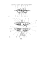
На фиг. 1 на общих видах спереди и сверху соответственно а) и б) изображен БКАК с V-образным оперением и тандемными полуэллиптическими крыльями, имеющими полукольцевые каналы с арочными поверхностями, открытыми сверху.In FIG. 1, in general front and top views a) and b), respectively, depicts a BKAK with a V-shaped plumage and tandem semi-elliptical wings having semicircular channels with arched surfaces open from above.
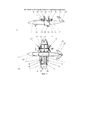
На фиг. 2 на общих видах сбоку и сверху соответственно а) и б) изображен БКАК с килями обратной стреловидности V-образного оперения и эллиптическим крылом с едиными полукольцевыми каналами, передние левый и правый винты которых работают по толкающей и тянущей схеме, и концевыми частями крыла, имеющими при виде спереди наравне с ЦПП и ЦПЗ вид серповидной конфигурации, закрытой сверху.In FIG. 2 in general side and top views a) and b), respectively, depicts a BKAK with reverse sweep keels of the V-shaped plumage and an elliptical wing with single semicircular channels, the front left and right screws of which work according to the pushing and pulling pattern, and the wing end parts having when viewed from the front along with the CPP and CPP, the view of the crescent configuration is closed from above.
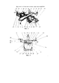
На общих видах изображены на фиг. 3 в изометрической проекции двухкилевой и сверху фиг. 4 двухбалочной схемы ГКАК с разновеликими винтами, два передних из них больших винта смонтированы на поворотных концевых частях полуэллиптического крыла, имеющего полукольцевой канал-центроплан с двумя задними меньшими винтами, установленными на левом и правом ЦПЗ с эллиптической задней кромкой.In general views are shown in FIG. 3 in an isometric view of two-keel and on top of FIG. 4 double-beam GKAK circuits with different-sized screws, two front of them large screws are mounted on the rotary end parts of a semi-elliptical wing, with a semicircular canal-center section with two rear smaller screws mounted on the left and right CPP with an elliptical trailing edge.
Беспилотный конвертоплан с арочным крылом имеет из композитного углепластика планер по схеме высокоплан с тандемными и эллиптическим крыльями, представлен на фиг. 1-2, содержит фюзеляж 1 с передним 2 и задним 3 разрезными крыльями. В вырезах каждого крыла с близким расположением установлены как передняя секция арочного крыла - полукольцевой канал 4 с внутренним передним ребром 5 жесткости и концевой частью 6, так и задняя секция - ЦПЗ 7, имеющий при виде спереди конфигурацию типа чайка, но и над изломом последней гондолу 8 с редуктором тянущего трехлопастного винта 9. Концевые части 5 полуэллиптических крыльев 2 и 3 снабжены соответственно закрылками 10 и элевонами 11. Развитое V-образное оперение 12 имеет полуэллиптические кили с рулевыми поверхностями 13 (см. фиг. 1).An unmanned convertiplane with an arched wing has a composite carbon fiber glider according to the high-plan model with tandem and elliptical wings, shown in FIG. 1-2, contains the
Для уменьшения длины продольного вала Н-образной трансмиссии объединенный полукольцевой канал имеет переднюю 15 (см. фиг. 2) и заднюю 4 арочные секции эллиптического крыла 14, выполненные открытыми сверху, установлены в центральной части фюзеляжа 1 и центре масс. Концевые части 6 с элеронами 16 эллиптического крыла 14, передние и задние части которого соответственно с винтами 17 и 9 и их гондолами 8 размещены на ЦПП 18 и ЦПЗ 7, отклоняемых вверх и обратно соответственно от полукольцевых секций 15 и 4. Полуэллиптическое V-образное оперение обратной стреловидности, килевые поверхности 19 с рулевыми поверхностями 20 которого имеют переднюю кромку, размещенную при виде сбоку параллельно радиусам секторного выреза, образованного концевыми крылышками 21 (см. фиг. 2а). Трехопорное колесное шасси имеет переднюю его опору 22, убирающуюся в носовую нишу фюзеляжа 1, оснащено основными их подкрыльными опорами 23 с неубирающимися амортизационными колесами в обтекателях 24, смонтированных снаружи в нижней части их полукольцевых каналов 4 задней секции эллиптического крыла 14 (см. фиг. 2) и арочной секции 32 полуэллиптического крыла (см. фиг. 3 и 4).To reduce the length of the longitudinal shaft of the H-shaped transmission, the combined semicircular channel has a front 15 (see Fig. 2) and rear 4 arched sections of the
Для упрощения конструкции ГКАК может иметь Н- или П-образное оперения на концах фюзеляжа 1 или тонких разнесенных балок 25 с киль-шайбами 26, отклоненными к плоскости симметрии и имеющими рули направления 27 и стабилизатор 28 с рулями высоты 29 (см. фиг. 3-4). Разнесенные балки 25 смонтированы на верхних частях и по внешним бортам развитого полукольцевого канала-центроплана 30. Вдоль продольной оси последнего смонтирован короткий фюзеляж-гондола 31, имеющий по внешним бортам полукольцевые секции 32 для тянущих меньших левого 33 и правого 34 винтов в гондолах 35, смонтированных на ЦПЗ 36, выполненных в поперечной плоскости при виде спереди в виде серповидных несущих поверхностей, закрытых сверху. Большие тянущие левый 37 и правый 38 винты с гондолами 39 их редукторов смонтированы на законцовках цельно-поворотных концевых частей 40 с элеронами 41 полуэллиптического (секции 30, 36 и 40) разрезного крыла 42 (см. фиг. 4).To simplify the design, the HCC can have an H- or U-shaped tail at the ends of the
Силовая установка ГКАК (см. фиг. 3 и 4) выполнена электрической и по параллельно-последовательной гибридной технологии, в которой два электромотора, вращательно связанные с задними меньшими винтами, и ТДД, вращательно связанные с передними большими винтами. При этом ОЭМГ вращательно связан с коробкой передач, подключаемой ОЭМГ, работающий как электромотор, к входному валу главного редуктора, увеличивая взлетную мощность на режимах ВВП и зависания либо к ТДД, передающему крутящий момент и на главный редуктор трансмиссии, и на ОЭМГ, работающий как генератор, для выработки генерирующей электрической мощности и подзарядки аккумуляторов в горизонтальном полете (на фиг. 3 и 4 не показано).The power plant GKAK (see Fig. 3 and 4) is made of electric and parallel-serial hybrid technology, in which two electric motors rotationally connected to the rear smaller screws, and TDD, rotationally connected to the front large screws. In this case, the OEMG is rotationally connected to the gearbox, which is connected as an electric motor, to the input shaft of the main gearbox, increasing the take-off power in the GDP and hover modes, either to the TDD, which transmits torque to the main gearbox of the transmission, and to the OEMG working as a generator , to generate generating electric power and recharge the batteries in horizontal flight (not shown in Fig. 3 and 4).
Управление (четырехвинтовыми БКАК и ГКАК идентично) приводится на примере БКАК (см. фиг. 2), которое обеспечивается общим и дифференциальным изменением шага поворотных двух передних 17 и двух задних 9 винтов и отклонением рулевых поверхностей 16 и 20, работающих в зоне активного обдува этих винтов. При крейсерском полете подъемная сила создается крылом 14, горизонтальная тяга - винтами 17 и 9, на режиме висения только винтами 17 и 9, на режиме перехода - крылом 14 с винтами 17 и 9. При переходе с самолетного режима полета на режим висения и если возникает момент тангажа (Mz), то он парируется отклонением рулей высоты 20, создающих, работая в зоне обдува двух задних винтов 9, парирующую силу. После установки поворотных винтов двух передних 17 и двух задних 9 в вертикальное положение вдоль линий вертикальной их тяги обеспечивается возможность вертолетных режимов полета. При этом в данной конфигурации четырехвинтовой несущей схемы реактивные моменты от двух передних 17 и двух задних 9 компенсируются полностью за счет взаимно противоположного их вращения в каждой группе винтов. Поворотные передние 17 и задние 9 винты отклоняются от горизонтального положения в вертикальное на угол 90° и наклонное 45° соответственно при выполнении ВВП и КВП на вертолетных и самолетных режимах полета БКАК. При висении на вертолетных режимах полета продольное управление БКАК осуществляется изменением шага винтов передней 17 и задней группы 9, путевое управление - изменением крутящих моментов каждой группы винтов, имеющих одинаковое направление вращения в диагонально расположенных группах винтов, например передний левый 17 винт с правым задним 9 винтом и передний правый 17 винт с левым задним 9 винтом (см. фиг. 2б). Поперечное управление обеспечивается изменением шага левой группы 17-9 и правой 9-17 несущих винтов, осуществляющих поперечную балансировку при одновременном соответствующем изменении шага двух передних винтов 17, обеспечивающих при этом продольную стабилизацию в связи с изменяемой продольной балансировкой. После вертикального взлета и набора высоты для перехода на самолетный режим полета поворотные винты передние 17 и задние 9 синхронно устанавливаются в горизонтальное положение (см. фиг. 2а). После чего производится крейсерский полет, при котором путевое управление обеспечивается рулевыми поверхностями 20. Продольное и поперечное управление может осуществляться синфазным и дифференциальным отклонением рулевых поверхностей 20 V-образного оперения 19 обратной стреловидности и элеронов 16 эллиптического крыла 14 соответственно.The control (four-screw BKAK and GKAK identical) is given on the example of the BKAK (see Fig. 2), which is provided by the general and differential change in the pitch of the rotary two
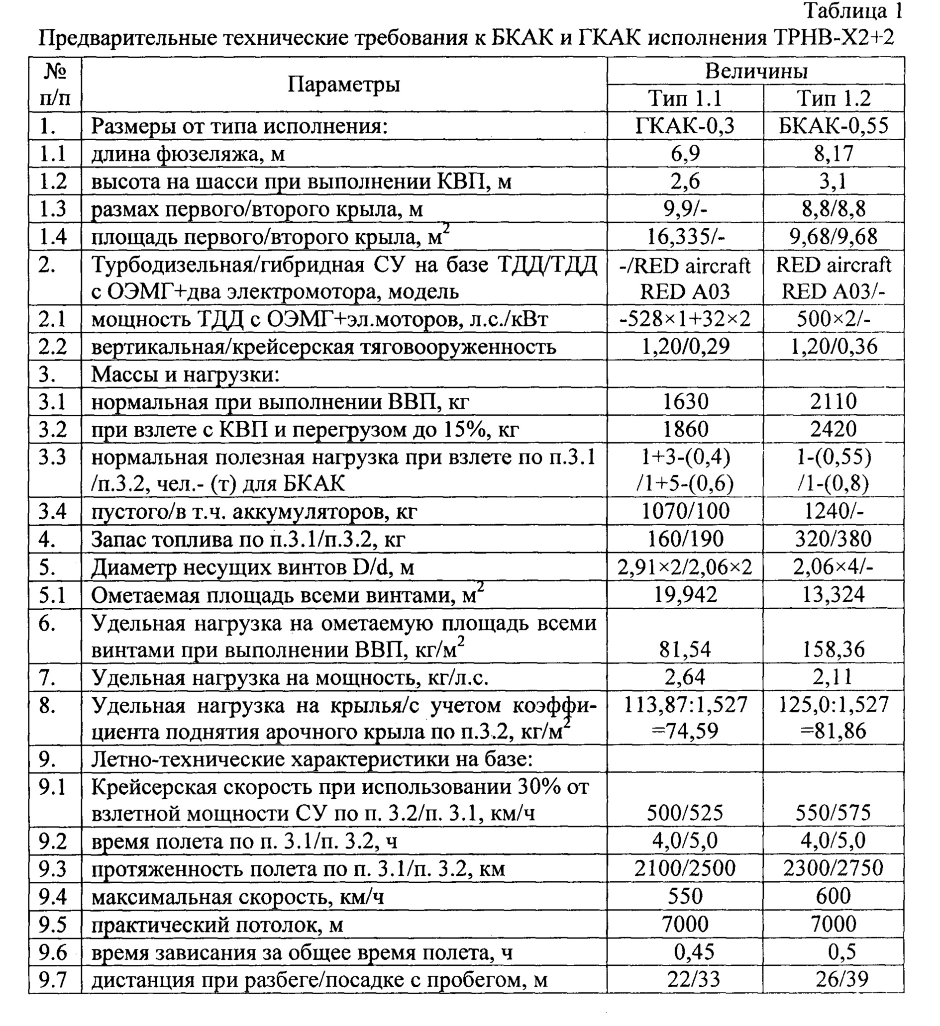
Таким образом, БКАК исполнения ТРНВ-Х2+2 с аэродинамической схемой тандем высокоплан, имеющий переднее и заднее арочные крылья с соответствующими винтами на ЦПЗ и V-образное оперение, представляет собой четырехвинтовой беспилотный конвертоплан. При выборе такой схемы БКАК большую роль играет необходимость обеспечения условий безопасного его использования на протяженных трассах при длительном времени крейсерского режима полета в самолетной конфигурации, но и, особенно, при выполнении переходного маневра, заходе на зависание и во время самой вертикальной посадки. Снижение аварийности достигается уменьшением скорости полета и принятием специальных мер (тандемная схема с арочными полуэллиптическими крыльями обеспечат соответственно хорошие противосрывные и противоштопорные характеристики). Ожидаемый эффект от такой конструкции - ощутимое уменьшение взлетной и скорости сваливания в 1,41 раза меньше, чем если арочное крыло было заменено традиционным сечением крыла, что позволит удвоить время барражирующего полета. В конечном итоге широкие эксплуатационные требования к конвертопланам нового поколения, несомненно, приведут к освоению скоростных БКАК и ГКАК, позволяющих реализовать высокие технико-экономические результаты (см. табл. 1) и достойно конкурировать с корпорацией IAI (Израиль).Thus, the BKAK version TRNV-X2 + 2 with an aerodynamic tandem tandem aeroplane model, having front and rear arched wings with corresponding propellers on the central landing gear and V-tail, is a four-screw unmanned tiltrotor. When choosing such a BCCA scheme, an important role is played by the need to ensure the conditions for its safe use on long routes with a long cruising flight mode in an airplane configuration, but also, especially when performing a transitional maneuver, hovering and during the vertical landing itself. Reducing accidents is achieved by reducing flight speed and taking special measures (a tandem scheme with arched semi-elliptical wings will provide good anti-tearing and anti-tearing characteristics, respectively). The expected effect of such a design is a noticeable decrease in take-off and stall speed of 1.41 times less than if the arched wing was replaced by a traditional wing section, which will double the time of a boarding flight. Ultimately, the wide operational requirements for the new generation of convertiplanes will undoubtedly lead to the development of high-speed BKAK and GKAK, which allow to achieve high technical and economic results (see Table 1) and compete adequately with the IAI corporation (Israel).
Claims (9)
Priority Applications (1)
| Application Number | Priority Date | Filing Date | Title |
|---|---|---|---|
| RU2017100220A RU2648503C1 (en) | 2017-01-09 | 2017-01-09 | Unmanned convertiplane with an arched wing |
Applications Claiming Priority (1)
| Application Number | Priority Date | Filing Date | Title |
|---|---|---|---|
| RU2017100220A RU2648503C1 (en) | 2017-01-09 | 2017-01-09 | Unmanned convertiplane with an arched wing |
Publications (1)
| Publication Number | Publication Date |
|---|---|
| RU2648503C1 true RU2648503C1 (en) | 2018-03-26 |
Family
ID=61708110
Family Applications (1)
| Application Number | Title | Priority Date | Filing Date |
|---|---|---|---|
| RU2017100220A RU2648503C1 (en) | 2017-01-09 | 2017-01-09 | Unmanned convertiplane with an arched wing |
Country Status (1)
| Country | Link |
|---|---|
| RU (1) | RU2648503C1 (en) |
Cited By (8)
| Publication number | Priority date | Publication date | Assignee | Title |
|---|---|---|---|---|
| RU185522U1 (en) * | 2018-07-23 | 2018-12-07 | Сергей Павлович Шульдяков | Unmanned aerial vehicle |
| CN109018321A (en) * | 2018-07-02 | 2018-12-18 | 寇冠 | Driven rotor craft |
| EP3741671A1 (en) * | 2019-04-12 | 2020-11-25 | The Boeing Company | Hybrid multirotor vehicles |
| RU2757693C1 (en) * | 2021-05-24 | 2021-10-20 | Закрытое акционерное общество "Инновационный центр "Бирюч" (ЗАО "ИЦ "Бирюч") | Vertical take-off and landing aircraft with propellers on rotary wing flaps |
| CN113682099A (en) * | 2021-10-12 | 2021-11-23 | 飞行空间(惠州)科技有限公司 | Flying vehicle |
| CN114750938A (en) * | 2022-03-16 | 2022-07-15 | 朱世友 | A light electric vertical lift aircraft |
| RU2812011C1 (en) * | 2023-09-25 | 2024-01-22 | Общество С Ограниченной Ответственностью "Завод Сигнал" | Uav from standardized parts and assemblies and production method |
| CN117585206A (en) * | 2023-11-29 | 2024-02-23 | 江西洪都航空工业股份有限公司 | A dual-mode quadcopter |
Citations (5)
| Publication number | Priority date | Publication date | Assignee | Title |
|---|---|---|---|---|
| US2032848A (en) * | 1934-11-26 | 1936-03-03 | Kutnar Virgil | Airplane |
| RU2096262C1 (en) * | 1993-06-01 | 1997-11-20 | Юрий Степанович Баканов | Arched wing aircraft |
| WO2009069109A2 (en) * | 2007-11-14 | 2009-06-04 | Vestal Ltd | Wing and a multiple propeller aircraft |
| RU152795U1 (en) * | 2015-01-28 | 2015-06-20 | Федеральное государственное унитарное предприятие "Государственный научно-исследовательский институт прикладных проблем" (ФГУП "ГосНИИПП) | AIRCRAFT |
| RU2582743C1 (en) * | 2014-12-02 | 2016-04-27 | Дмитрий Сергеевич Дуров | Aircraft vertical take-off system |
-
2017
- 2017-01-09 RU RU2017100220A patent/RU2648503C1/en not_active IP Right Cessation
Patent Citations (5)
| Publication number | Priority date | Publication date | Assignee | Title |
|---|---|---|---|---|
| US2032848A (en) * | 1934-11-26 | 1936-03-03 | Kutnar Virgil | Airplane |
| RU2096262C1 (en) * | 1993-06-01 | 1997-11-20 | Юрий Степанович Баканов | Arched wing aircraft |
| WO2009069109A2 (en) * | 2007-11-14 | 2009-06-04 | Vestal Ltd | Wing and a multiple propeller aircraft |
| RU2582743C1 (en) * | 2014-12-02 | 2016-04-27 | Дмитрий Сергеевич Дуров | Aircraft vertical take-off system |
| RU152795U1 (en) * | 2015-01-28 | 2015-06-20 | Федеральное государственное унитарное предприятие "Государственный научно-исследовательский институт прикладных проблем" (ФГУП "ГосНИИПП) | AIRCRAFT |
Cited By (11)
| Publication number | Priority date | Publication date | Assignee | Title |
|---|---|---|---|---|
| CN109018321A (en) * | 2018-07-02 | 2018-12-18 | 寇冠 | Driven rotor craft |
| RU185522U1 (en) * | 2018-07-23 | 2018-12-07 | Сергей Павлович Шульдяков | Unmanned aerial vehicle |
| EP3741671A1 (en) * | 2019-04-12 | 2020-11-25 | The Boeing Company | Hybrid multirotor vehicles |
| US11891166B2 (en) | 2019-04-12 | 2024-02-06 | The Boeing Company | Hybrid multirotor vehicles and related methods |
| RU2757693C1 (en) * | 2021-05-24 | 2021-10-20 | Закрытое акционерное общество "Инновационный центр "Бирюч" (ЗАО "ИЦ "Бирюч") | Vertical take-off and landing aircraft with propellers on rotary wing flaps |
| CN113682099A (en) * | 2021-10-12 | 2021-11-23 | 飞行空间(惠州)科技有限公司 | Flying vehicle |
| CN113682099B (en) * | 2021-10-12 | 2024-04-16 | 飞行空间(惠州)科技有限公司 | A flying car |
| CN114750938A (en) * | 2022-03-16 | 2022-07-15 | 朱世友 | A light electric vertical lift aircraft |
| RU2816404C1 (en) * | 2023-04-03 | 2024-03-28 | Дмитрий Сергеевич Дуров | Combat aircraft complex with unmanned aerial vehicle |
| RU2812011C1 (en) * | 2023-09-25 | 2024-01-22 | Общество С Ограниченной Ответственностью "Завод Сигнал" | Uav from standardized parts and assemblies and production method |
| CN117585206A (en) * | 2023-11-29 | 2024-02-23 | 江西洪都航空工业股份有限公司 | A dual-mode quadcopter |
Similar Documents
| Publication | Publication Date | Title |
|---|---|---|
| RU2648503C1 (en) | Unmanned convertiplane with an arched wing | |
| RU2448869C1 (en) | Multipurpose multi-tiltrotor helicopter-aircraft | |
| RU2527248C1 (en) | Drone with hybrid power plant (versions) | |
| RU2627965C1 (en) | High-speed amphibious rotorcraft | |
| RU2661277C1 (en) | Unmanned carrier-based convertible rotorcraft | |
| RU2629475C1 (en) | High-speed turbofan combined helicopter | |
| KR20220029575A (en) | Vertical take-off and landing aircraft using a fixed forward tilted rotor to simulate rigid wing aerodynamics | |
| CN101875399A (en) | A kind of tilt rotor aircraft adopting side-by-side coaxial twin rotors | |
| RU2657706C1 (en) | Convertiplane | |
| RU2629478C2 (en) | High-speed helicopter with propulsion-steering system | |
| RU2351506C2 (en) | Multipurpose hydroconvertipropeller plane | |
| RU2548304C1 (en) | Multirotor convertible high-speed helicopter | |
| US7370828B2 (en) | Rotary wing aircraft | |
| RU2547155C1 (en) | Multi-rotor unmanned electroconvertible aircraft | |
| RU2521090C1 (en) | High-speed turboelectric helicopter | |
| RU2492112C1 (en) | Heavy-duty multi-propeller converter plate | |
| RU2532672C1 (en) | Heavy convertible electric drone | |
| RU2652863C1 (en) | High-speed hybrid helicopter-aircraft | |
| RU2542805C1 (en) | Vtol aircraft with hybrid power plant | |
| RU2618832C1 (en) | Multirotor high-speed combined helicopter | |
| RU2582743C1 (en) | Aircraft vertical take-off system | |
| RU2648937C1 (en) | Aeromobile of hover take-off | |
| RU2611480C1 (en) | Multi-screw unmanned rotorcraft | |
| RU2543120C1 (en) | Multirotor hybrid electrical convertiplane | |
| RU2609856C1 (en) | Fast-speed convertible compound helicopter |
Legal Events
| Date | Code | Title | Description |
|---|---|---|---|
| MM4A | The patent is invalid due to non-payment of fees |
Effective date: 20190110 |