RU2639460C2 - Box of actuators for power selection from the gas turbine engine containing the assembly casing - Google Patents
Box of actuators for power selection from the gas turbine engine containing the assembly casing Download PDFInfo
- Publication number
- RU2639460C2 RU2639460C2 RU2015119673A RU2015119673A RU2639460C2 RU 2639460 C2 RU2639460 C2 RU 2639460C2 RU 2015119673 A RU2015119673 A RU 2015119673A RU 2015119673 A RU2015119673 A RU 2015119673A RU 2639460 C2 RU2639460 C2 RU 2639460C2
- Authority
- RU
- Russia
- Prior art keywords
- housing
- sections
- gears
- gas turbine
- turbine engine
- Prior art date
Links
Images
Classifications
-
- F—MECHANICAL ENGINEERING; LIGHTING; HEATING; WEAPONS; BLASTING
- F02—COMBUSTION ENGINES; HOT-GAS OR COMBUSTION-PRODUCT ENGINE PLANTS
- F02C—GAS-TURBINE PLANTS; AIR INTAKES FOR JET-PROPULSION PLANTS; CONTROLLING FUEL SUPPLY IN AIR-BREATHING JET-PROPULSION PLANTS
- F02C7/00—Features, components parts, details or accessories, not provided for in, or of interest apart form groups F02C1/00 - F02C6/00; Air intakes for jet-propulsion plants
- F02C7/32—Arrangement, mounting, or driving, of auxiliaries
-
- B—PERFORMING OPERATIONS; TRANSPORTING
- B60—VEHICLES IN GENERAL
- B60K—ARRANGEMENT OR MOUNTING OF PROPULSION UNITS OR OF TRANSMISSIONS IN VEHICLES; ARRANGEMENT OR MOUNTING OF PLURAL DIVERSE PRIME-MOVERS IN VEHICLES; AUXILIARY DRIVES FOR VEHICLES; INSTRUMENTATION OR DASHBOARDS FOR VEHICLES; ARRANGEMENTS IN CONNECTION WITH COOLING, AIR INTAKE, GAS EXHAUST OR FUEL SUPPLY OF PROPULSION UNITS IN VEHICLES
- B60K25/00—Auxiliary drives
-
- F—MECHANICAL ENGINEERING; LIGHTING; HEATING; WEAPONS; BLASTING
- F16—ENGINEERING ELEMENTS AND UNITS; GENERAL MEASURES FOR PRODUCING AND MAINTAINING EFFECTIVE FUNCTIONING OF MACHINES OR INSTALLATIONS; THERMAL INSULATION IN GENERAL
- F16H—GEARING
- F16H57/00—General details of gearing
- F16H57/02—Gearboxes; Mounting gearing therein
- F16H57/033—Series gearboxes, e.g. gearboxes based on the same design being available in different sizes or gearboxes using a combination of several standardised units
-
- B—PERFORMING OPERATIONS; TRANSPORTING
- B64—AIRCRAFT; AVIATION; COSMONAUTICS
- B64D—EQUIPMENT FOR FITTING IN OR TO AIRCRAFT; FLIGHT SUITS; PARACHUTES; ARRANGEMENTS OR MOUNTING OF POWER PLANTS OR PROPULSION TRANSMISSIONS IN AIRCRAFT
- B64D41/00—Power installations for auxiliary purposes
- B64D2041/002—Mounting arrangements for auxiliary power units (APU's)
-
- B—PERFORMING OPERATIONS; TRANSPORTING
- B64—AIRCRAFT; AVIATION; COSMONAUTICS
- B64D—EQUIPMENT FOR FITTING IN OR TO AIRCRAFT; FLIGHT SUITS; PARACHUTES; ARRANGEMENTS OR MOUNTING OF POWER PLANTS OR PROPULSION TRANSMISSIONS IN AIRCRAFT
- B64D41/00—Power installations for auxiliary purposes
- B64D41/007—Ram air turbines
-
- Y—GENERAL TAGGING OF NEW TECHNOLOGICAL DEVELOPMENTS; GENERAL TAGGING OF CROSS-SECTIONAL TECHNOLOGIES SPANNING OVER SEVERAL SECTIONS OF THE IPC; TECHNICAL SUBJECTS COVERED BY FORMER USPC CROSS-REFERENCE ART COLLECTIONS [XRACs] AND DIGESTS
- Y10—TECHNICAL SUBJECTS COVERED BY FORMER USPC
- Y10S—TECHNICAL SUBJECTS COVERED BY FORMER USPC CROSS-REFERENCE ART COLLECTIONS [XRACs] AND DIGESTS
- Y10S74/00—Machine element or mechanism
- Y10S74/05—Gas turbine with gearing
-
- Y—GENERAL TAGGING OF NEW TECHNOLOGICAL DEVELOPMENTS; GENERAL TAGGING OF CROSS-SECTIONAL TECHNOLOGIES SPANNING OVER SEVERAL SECTIONS OF THE IPC; TECHNICAL SUBJECTS COVERED BY FORMER USPC CROSS-REFERENCE ART COLLECTIONS [XRACs] AND DIGESTS
- Y10—TECHNICAL SUBJECTS COVERED BY FORMER USPC
- Y10T—TECHNICAL SUBJECTS COVERED BY FORMER US CLASSIFICATION
- Y10T74/00—Machine element or mechanism
- Y10T74/21—Elements
- Y10T74/2186—Gear casings
Abstract
Description
Изобретение относится к коробке приводов для отбора мощности от газотурбинного двигателя, предназначенной для передачи движения от газотурбинного двигателя через выходящий из него радиальный вал на различные вспомогательные устройства, связанные с газотурбинным двигателем, такие как насосы, электрогенераторы и т.д., которые необходимы для работы газотурбинного двигателя, или на другие устройства летательного аппарата, приводимого в движение этим газотурбинным двигателем. Согласно изобретению корпус коробки является сборным и содержит соединенные между собой участки.The invention relates to a drive box for power take-off from a gas turbine engine, designed to transmit movement from a gas turbine engine through a radial shaft emerging from it to various auxiliary devices associated with a gas turbine engine, such as pumps, electric generators, etc., which are necessary for operation a gas turbine engine, or other devices of an aircraft driven by this gas turbine engine. According to the invention, the box body is prefabricated and contains interconnected sections.
Коробка приводов, по существу, содержит внутри корпуса кинематическую цепь, включающую в себя совокупность зубчатых колес, зацепляющихся между собой таким образом, чтобы передавать движение от радиального вала на устройства. Таким образом, эта цепь связана с радиальным валом газотурбинного двигателя и с валами отбора мощности устройств. Коробка приводов прикреплена к газотурбинному двигателю в необходимом положении, а устройства, в свою очередь, прикреплены к коробке приводов. В документе US-A-12/0006137 описана известная конструкция коробки приводов. Здесь же кратко представлены приводной вал газотурбинного двигателя, радиальный вал и собственно коробка приводов, содержащая кинематическую цепь внутри корпуса, состоящую из прямозубых зубчатых колес. Устройство находится на коробке противоположно креплению к газотурбинному двигателю. Все оси зубчатых колес являются параллельными, и эта известная коробка содержит единую линию зубчатой передачи.The drive box essentially contains a kinematic chain inside the housing, which includes a set of gears engaged with each other so as to transmit movement from the radial shaft to the device. Thus, this circuit is connected with the radial shaft of the gas turbine engine and with the power take-off shafts of the devices. The drive box is attached to the gas turbine engine in the required position, and the devices, in turn, are attached to the drive box. US-A-12/0006137 describes a known drive box design. Here, a drive shaft of a gas turbine engine, a radial shaft, and a drive box proper, containing a kinematic chain inside the housing, consisting of spur gears, are briefly presented. The device is located on the box opposite the mount to the gas turbine engine. All gear axles are parallel, and this known box contains a single gear line.
В данном случае линией зубчатой передачи называют набор смежных зубчатых колес, принадлежащих кинематической цепи и в принципе зацепляющихся между собой, при этом зубчатые колеса расположены в одной плоскости или в параллельных плоскостях; иначе говоря, все оси вращения зубчатых колес являются параллельными (перпендикулярными к этой плоскости или к этим параллельным плоскостям), и считается, что зубчатые колеса, которые напрямую зацепляются между собой, находятся в одной плоскости; вместе с тем, линия зубчатой передачи может быть расположена в параллельных плоскостях, если существуют зубчатые колеса, расположенные в линию вдоль одной оси вращения.In this case, a gear line is a set of adjacent gears that belong to a kinematic chain and, in principle, mesh with each other, while the gears are located in the same plane or in parallel planes; in other words, all the axes of rotation of the gears are parallel (perpendicular to this plane or to these parallel planes), and it is believed that the gears that are directly engaged among themselves are in the same plane; however, the gear line may be arranged in parallel planes if there are gears arranged in a line along one axis of rotation.
Исследования для уменьшения габаритного размера заставляют использовать преимущественно коробки приводов, кинематическая цепь которых содержит множество линий зубчатых передач в разных плоскостях вместо единой линии зубчатой передачи в обычной конструкции. Эти линии зубчатых передач расположены последовательно и связаны между собой соединительными зубчатыми передачами с непараллельными осями. Действительно, извилистая форма, которую при этом принимает кинематическая цепь, позволяет ей оставаться смежной с газотурбинным двигателем по всей своей длине, что позволяет одновременно избегать больших радиальных, осевых и угловых габаритных размеров, неизбежных, когда присутствует только одна линия зубчатой передачи, которая должна иметь определенную длину, то есть все эти большие габаритные размеры являются недостатком.Studies to reduce the overall size make it necessary to use mainly gearboxes, the kinematic chain of which contains many gear lines in different planes instead of a single gear line in a conventional design. These gear lines are arranged in series and interconnected by connecting gears with non-parallel axes. Indeed, the sinuous shape that the kinematic chain takes in this case allows it to remain adjacent to the gas turbine engine along its entire length, which allows us to simultaneously avoid the large radial, axial and angular dimensions that are unavoidable when there is only one gear line, which should have a certain length, that is, all of these large overall dimensions are a drawback.
Чтобы обеспечить уменьшение габарита, было бы логично, чтобы корпус коробки приводов состоял из частей, в каждой из которых расположена одна из линий зубчатых передач, причем эти части имеют основные направления протяженности, совпадающие с направлениями их линий зубчатых передач, однако при этом повышается стоимость изготовления корпуса независимо от того, применяют литье или механическую обработку, так как необходимо либо изготовить сложную литейную форму, либо снять большое количество материала, что к тому же влечет за собой усложнение операции литья или увеличение времени на механическую обработку.In order to ensure a reduction in size, it would be logical for the case of the gearbox to consist of parts, in each of which one of the gear lines is located, and these parts have main length directions that coincide with the directions of their gear lines, however, this increases the manufacturing cost cases regardless of whether casting or machining is used, since it is necessary either to make a complex casting mold or to remove a large amount of material, which also entails more complexity ue casting operation or increase in the time for machining.
Основной задачей изобретения является снижение стоимости изготовления корпуса коробки приводов, состоящего из множества последовательных частей, проходящих в разных направлениях, и, следовательно, привлечь интерес к использованию коробок приводов, кинематическая цепь которых состоит из множества линий зубчатых передач.The main objective of the invention is to reduce the cost of manufacturing the housing of the gearbox, consisting of many successive parts extending in different directions, and, therefore, to attract interest in the use of gearboxes, the kinematic chain of which consists of many gear lines.
Согласно изобретению корпус состоит из отдельных участков простой формы, соответствующих его частям и объединенных друг с другом на границах соединения после раздельного изготовления. Эти участки, как правило, имеют простую, например, прямолинейную или дугообразную форму и являются достаточно короткими, что позволяет уменьшить общую стоимость изготовления по сравнению с единым корпусом и даже по сравнению с корпусом обычной коробки с единой линией зубчатой передачи, который является дорогим в изготовлении по причине большой длины, даже если его форма является простой.According to the invention, the housing consists of separate sections of simple shape, corresponding to its parts and combined with each other at the borders of the connection after separate manufacture. These sections, as a rule, have a simple, for example, rectilinear or arched shape and are quite short, which allows to reduce the total cost of production compared to a single case and even compared to the case of a conventional box with a single gear transmission line, which is expensive to manufacture due to the length, even if its shape is simple.
Предпочтительно границы соединения между объединенными участками корпуса совпадают с границами соединения линий зубчатых передач (зацепляющиеся участки соединительных зубчатых передач), поэтому концы линий зубчатых передач доходят до концов участков корпуса перед их объединением, но не выступая из них явно, что облегчает манипулирование участками коробки приводов, а затем их соединение. Вместе с тем, это совпадение границ соединения не является обязательным. Если оно существует, можно предусмотреть несколько вариантов выполнения. Граница соединения может быть расположена под углом к частям, и в этом случае соединительная зубчатая передача состоит из конических или прямозубых зубчатых колес; граница соединения может находиться на одной из главных сторон одного из участков корпуса, и в этом случае соединительная зубчатая передача будет состоять из конических или прямозубых зубчатых колес.Preferably, the boundaries of the connection between the combined sections of the housing coincide with the boundaries of the connection of the lines of the gears (engaging sections of the connecting gears), therefore, the ends of the lines of the gears reach the ends of the sections of the housing before combining them, but without protruding clearly, which facilitates the manipulation of the sections of the gearbox and then their connection. However, this coincidence of the boundaries of the connection is optional. If it exists, several embodiments may be envisaged. The boundary of the connection may be located at an angle to the parts, in which case the connecting gear consists of bevel or spur gears; the boundary of the connection can be on one of the main sides of one of the sections of the housing, in which case the connecting gear will consist of bevel or spur gears.
Далее следует описание некоторых вариантов осуществления изобретения со ссылками на чертежи, при этом должно быть понятно, что возможны также другие варианты осуществления и описание не является ограничительным.The following is a description of some embodiments of the invention with reference to the drawings, it being understood that other embodiments are also possible and the description is not restrictive.
На фиг. 1, 2, 3 и 4 показана коробка приводов в соответствии с изобретением;In FIG. 1, 2, 3, and 4 show a drive box in accordance with the invention;
на фиг. 5, 6 и 7 - варианты применения коробки приводов согласно изобретению.in FIG. 5, 6 and 7 illustrate applications of the drive box according to the invention.
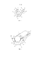
Коробка приводов согласно варианту осуществления раскрыта со ссылками на первые фиг. 1-4. Как показано на фиг. 1, она имеет трехмерную форму, включая наружный корпус с двумя параллельными и прямолинейными концевыми частями 1 и 2 и частично круговой средней частью 3, соединяющей вышеуказанные части и перпендикулярной к ним. На фиг. 2 показано, что эта коробка приводов может быть преимущественно расположена вокруг газотурбинного двигателя 4, например, в месте его рабочей части высокого давления, при этом концевые части 1 и 2 расположены в осевом направлении указанного газотурбинного двигателя на диаметрально противоположных образующих, а средняя часть 3 соответственно охватывает газотурбинный двигатель 4, делая вокруг него половину оборота. Отбор мощности газотурбинного двигателя может происходить непосредственно от обычного радиального вала, принадлежащего газотурбинному двигателю 4, или через промежуточный вал, принадлежащий отдельному корпусу и зацепляющийся с радиальным валом. Некоторые возможные положения приводного (радиального или промежуточного) вала показаны ссылочным обозначением 9 на фиг. 1.A drive box according to an embodiment is disclosed with reference to the first FIGS. 1-4. As shown in FIG. 1, it has a three-dimensional shape, including an outer casing with two parallel and
Устройства 10, приводимые во вращение коробкой приводов, могут быть установлены на верхних 6, боковых 7 и передних 8 поверхностях, а также на радиально наружных поверхностях 11 средней части 3. Крепление коробки приводов на газотурбинном двигателе 4 может быть выполнено болтами в точках 12 крепления, находящихся на корпусе 13, возможно посредством клиньев или других промежуточных держателей между газотурбинным двигателем 4 и, например, некоторыми из внутренних поверхностей 5 коробки. Устройства 10 прикреплены к корпусу 13 в других точках 12 крепления.The
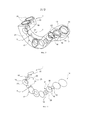
На фиг. 3 показано, что коробка приводов, по существу, состоит из корпуса 13, определяющего контур трех частей 1, 2 и 3, и кинематической цепи 14, которая находится в корпусе 13 и в которой имеется три линии 15, 16 и 17 зубчатых передач, соответственно расположенные в соответствующих частях 1, 2 и 3. Каждая из них содержит зубчатые колеса 18, как правило, с прямыми зубьями, зацепляющиеся между собой для образования прямых зубчатых передач, при этом оси 19 некоторых из этих зубчатых колес 18 служат для приведения во вращение подвижных частей устройств 10 и проходят через отверстия 20 корпуса 13. Число зубчатых колес 18, их диаметры и передаточные отношения, а также положения отверстий 20, ограничивающих оси 19 привода устройств 10, можно выбирать достаточно свободно в зависимости от скоростей вращений, которые необходимо передавать, и от положений устройств 10. Специальное отверстие 21 выполнено на входе приводного вала 9, который содержит ведущую шестерню 22, зацепляющуюся с каким-либо из зубчатых колес 18.In FIG. 3 shows that the drive box essentially consists of a
На фиг. 4 отдельно показана кинематическая цепь 14. Соединение между тремя линиями 15, 16 и 17 зубчатых передач происходит через соединительные зубчатые передачи 23 и 24 с не параллельными осями. Каждая из них может включать в себя первую коническую шестерню 25, неподвижно соединенную и коаксиальную с крайним зубчатым колесом 18 линии 17 зубчатой передачи, и вторую коническую шестерню 26, также неподвижно соединенную и коаксиальную с крайним зубчатым колесом 18 одной из других линий 15 или 16 зубчатых передач. Соединительные зубчатые передачи 23 и 24 обеспечивают, таким образом, непрерывность кинематической цепи 14 и способность ее приведения в движение только посредством ведущей шестерни 22. Они позволяют также ориентировать каждую из линий 15, 16 и 17 зубчатых передач в направлении части 1, 2 или 3 корпуса 13.In FIG. 4, the
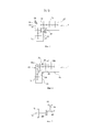
Далее следует более подробное описание изогнутых участков соединения между частями корпуса 13 в трехмерной коробке приводов изогнутой формы в соответствии с изобретением. Как показано на фиг. 5, можно поместить соединительную зубчатую передачу 23 (например) только в изгибе, образованном двумя последовательными частями (в данном случае 1 и 3). Поскольку непосредственно изготавливать корпус 13 сложной формы очень дорого, то в соответствии с изобретением его выполняют в виде участков, соответствующих каждой из частей, в данном случае участков 27 и 28 для частей 1 и 3, которые соединяют между собой болтовыми фланцами с установкой между ними уплотнительной прокладки или, в случае необходимости, промежуточного фланца.The following is a more detailed description of the curved sections of the connection between the parts of the
Согласно варианту выполнения, показанному на фиг. 5, фланцы 29 образуют границу соединения между участками 27 и 28 корпуса, которая проходит в плоскости, пересекающей изгиб, то есть под углом к главным направлениям протяженности частей 1 и 3 и, в частности, по диагонали изгиба. Соединение между коническими шестернями 25 и 26 расположено в этом случае на этой плоской границе соединения таким образом, что конические шестерни 25 и 26 доходят до отверстия участков 27 и 28 корпуса перед их сборкой и, кроме того, все зубчатые колеса 18 могут иметь параллельные оси 17 внутри каждого из участков 27 и 28 корпуса, при этом каждая из линий зубчатых передач принадлежит отдельному участку корпуса. Эти две особенности позволяют упростить изготовление корпуса и объединение его участков 27 и 28.According to the embodiment shown in FIG. 5, the
Другой предпочтительный возможный вариант осуществления представлен на фиг. 6. Граница соединения проходит в данном случае параллельно по отношению к главным сторонам частей 1 и 3, в данном случае в плоскости внутренней поверхности 31 части 3, и вместо торцевой поверхности части 1, причем эта граница соединения образована фланцами 30, аналогичными вышеуказанным фланцам. Преимуществом такой конструкции является то, что формы участков корпуса, в данном случае 45 и 46, не имеют скошенных концевых областей, то есть являются более простыми. Преимущество предыдущего варианта, в котором кинематическая цепь разделена на участки, концы которых доходят до границы соединения, можно сохранить, если коническая зубчатая передача соединения линий зубчатых передач, образованная коническими шестернями 25 и 26, полностью находится в одной из частей, в данном случае 3, и кинематическая цепь 14 содержит зубчатую передачу соединения, принадлежащую одной из линий зубчатых передач (в данном случае 15), и образована зубчатыми колесами 18 с прямыми зубьями, в данном случае обозначенными 18а и 18b, зацепляющимися в месте 47 контакта, которое совпадает с границей 30 соединения. Незначительным недостатком такой конструкции является то, что участок 46 корпуса содержит зубчатое колесо (18а), ось 19 которого имеет направление, отличное от направления других, и, следовательно, в этом месте изготовление является немного более сложным.Another preferred possible embodiment is shown in FIG. 6. In this case, the joint boundary extends parallel to the main sides of
Аналогичные конструкции могут быть выполнены для соединения между частями 2 и 3, которое не показано, и, в целом, для любого соединения частей разного направления, независимо от формы и, в частности, от угла, образуемого частями, и независимо от числа частей коробки приводов.Similar designs can be made for the connection between
Эквивалентное выполнение с точки зрения кинематики может быть предложено для замены конических шестерен 25 и 26 прямой шестерней 48 и зубчатым венцом 49 на плоскости, как показано на фиг. 7, но без изменения других элементов согласно варианту осуществления изобретения.An equivalent implementation from the point of view of kinematics can be proposed to replace the
Claims (10)
Applications Claiming Priority (3)
| Application Number | Priority Date | Filing Date | Title |
|---|---|---|---|
| FR1260242 | 2012-10-26 | ||
| FR1260242A FR2997467B1 (en) | 2012-10-26 | 2012-10-26 | TURBOMACHINE MOVEMENT GEAR BOX, COMPOSED OF ASSEMBLED CASING |
| PCT/FR2013/052545 WO2014064390A1 (en) | 2012-10-26 | 2013-10-24 | Power take-off gearbox on a turbomachine, consisting of an assembled housing |
Publications (2)
| Publication Number | Publication Date |
|---|---|
| RU2015119673A RU2015119673A (en) | 2016-12-27 |
| RU2639460C2 true RU2639460C2 (en) | 2017-12-21 |
Family
ID=47624303
Family Applications (1)
| Application Number | Title | Priority Date | Filing Date |
|---|---|---|---|
| RU2015119673A RU2639460C2 (en) | 2012-10-26 | 2013-10-24 | Box of actuators for power selection from the gas turbine engine containing the assembly casing |
Country Status (11)
| Country | Link |
|---|---|
| US (1) | US9316158B2 (en) |
| EP (1) | EP2912291B1 (en) |
| JP (1) | JP6218846B2 (en) |
| CN (1) | CN104968917B (en) |
| BR (1) | BR112015009233B1 (en) |
| CA (1) | CA2889030C (en) |
| ES (1) | ES2589114T3 (en) |
| FR (1) | FR2997467B1 (en) |
| PL (1) | PL2912291T3 (en) |
| RU (1) | RU2639460C2 (en) |
| WO (1) | WO2014064390A1 (en) |
Families Citing this family (5)
| Publication number | Priority date | Publication date | Assignee | Title |
|---|---|---|---|---|
| FR2995053B1 (en) * | 2012-09-03 | 2016-03-04 | Snecma | TURBOMACHINE MOVEMENT GEAR BOX COMPRISING A GEAR-LINKED CINEMA CHAIN EXTENDING IN NON-PARALLEL PLANS |
| FR3012845B1 (en) * | 2013-11-07 | 2015-10-23 | Snecma | TURBOMACHINE EQUIPPED WITH MEANS FOR RECOVERING THE THROTTLE EFFORTS OF ITS ENGINE |
| US10047827B2 (en) * | 2016-02-26 | 2018-08-14 | The Boeing Company | Low-profile, rotating-shaft transmission device, and associated method |
| US10502142B2 (en) * | 2017-04-11 | 2019-12-10 | United Technologies Corporation | Turbine engine gearbox assembly with sets of inline gears |
| FR3124545B1 (en) * | 2021-06-28 | 2023-06-23 | Safran Aircraft Engines | Assembly for an aircraft turbomachine comprising an equipment support |
Citations (5)
| Publication number | Priority date | Publication date | Assignee | Title |
|---|---|---|---|---|
| SU198058A1 (en) * | TRANSMISSION BOX FOR AUXILIARY UNITS OF AUTOMOBILE GAS TURBINE ENGINE | |||
| US20040012282A1 (en) * | 2002-03-22 | 2004-01-22 | Takashi Haga | Reduction gear for geared motor, geared motor, and product group thereof |
| US6840479B1 (en) * | 2003-12-05 | 2005-01-11 | The Boeing Company | Airframe mounted accessory drive (AMAD) power take-off shaft auxiliary power generation |
| US20120006137A1 (en) * | 2010-07-07 | 2012-01-12 | Hamilton Sundstrand Corporation | Gear driven accessory for gearbox |
| US20120117982A1 (en) * | 2010-11-17 | 2012-05-17 | Suciu Gabriel L | Axial accessory gearbox |
Family Cites Families (4)
| Publication number | Priority date | Publication date | Assignee | Title |
|---|---|---|---|---|
| US6142418A (en) * | 1998-05-12 | 2000-11-07 | Hamilton Sundstrand Corporation | Multi-path secondary power system for an aircraft |
| US7975465B2 (en) * | 2003-10-27 | 2011-07-12 | United Technologies Corporation | Hybrid engine accessory power system |
| US9068515B2 (en) * | 2011-12-07 | 2015-06-30 | United Technologies Corporation | Accessory gearbox with tower shaft removal capability |
| US8973465B2 (en) * | 2012-07-20 | 2015-03-10 | United Technologies Corporation | Gearbox for gas turbine engine |
-
2012
- 2012-10-26 FR FR1260242A patent/FR2997467B1/en active Active
-
2013
- 2013-10-24 JP JP2015538534A patent/JP6218846B2/en not_active Expired - Fee Related
- 2013-10-24 BR BR112015009233-0A patent/BR112015009233B1/en not_active IP Right Cessation
- 2013-10-24 CN CN201380056286.9A patent/CN104968917B/en active Active
- 2013-10-24 RU RU2015119673A patent/RU2639460C2/en active
- 2013-10-24 US US14/437,030 patent/US9316158B2/en active Active
- 2013-10-24 CA CA2889030A patent/CA2889030C/en not_active Expired - Fee Related
- 2013-10-24 EP EP13789880.5A patent/EP2912291B1/en active Active
- 2013-10-24 ES ES13789880.5T patent/ES2589114T3/en active Active
- 2013-10-24 WO PCT/FR2013/052545 patent/WO2014064390A1/en active Application Filing
- 2013-10-24 PL PL13789880.5T patent/PL2912291T3/en unknown
Patent Citations (5)
| Publication number | Priority date | Publication date | Assignee | Title |
|---|---|---|---|---|
| SU198058A1 (en) * | TRANSMISSION BOX FOR AUXILIARY UNITS OF AUTOMOBILE GAS TURBINE ENGINE | |||
| US20040012282A1 (en) * | 2002-03-22 | 2004-01-22 | Takashi Haga | Reduction gear for geared motor, geared motor, and product group thereof |
| US6840479B1 (en) * | 2003-12-05 | 2005-01-11 | The Boeing Company | Airframe mounted accessory drive (AMAD) power take-off shaft auxiliary power generation |
| US20120006137A1 (en) * | 2010-07-07 | 2012-01-12 | Hamilton Sundstrand Corporation | Gear driven accessory for gearbox |
| US20120117982A1 (en) * | 2010-11-17 | 2012-05-17 | Suciu Gabriel L | Axial accessory gearbox |
Also Published As
| Publication number | Publication date |
|---|---|
| CN104968917A (en) | 2015-10-07 |
| EP2912291B1 (en) | 2016-07-20 |
| JP6218846B2 (en) | 2017-10-25 |
| CA2889030A1 (en) | 2014-05-01 |
| RU2015119673A (en) | 2016-12-27 |
| JP2016500788A (en) | 2016-01-14 |
| FR2997467B1 (en) | 2016-07-29 |
| US9316158B2 (en) | 2016-04-19 |
| EP2912291A1 (en) | 2015-09-02 |
| CA2889030C (en) | 2019-11-05 |
| PL2912291T3 (en) | 2016-12-30 |
| BR112015009233B1 (en) | 2021-01-26 |
| US20150285153A1 (en) | 2015-10-08 |
| CN104968917B (en) | 2016-08-17 |
| ES2589114T3 (en) | 2016-11-10 |
| FR2997467A1 (en) | 2014-05-02 |
| WO2014064390A1 (en) | 2014-05-01 |
Similar Documents
| Publication | Publication Date | Title |
|---|---|---|
| RU2639460C2 (en) | Box of actuators for power selection from the gas turbine engine containing the assembly casing | |
| RU2641777C2 (en) | Gear box for power take-off in gas turbine engine consisting of kinematic circuit with engagement lines arranged in non-parallel planes | |
| US9278760B2 (en) | Torque split gearbox for rotary wing aircraft | |
| CN105202132B (en) | Multi-speed transmission | |
| RU2686967C2 (en) | Accessory gearbox (versions) and gas turbine engine | |
| JP2005240800A (en) | Mechanical driving system for accessory gear box | |
| US20160025203A1 (en) | Wave generator of strain wave gearing | |
| JP2005241006A (en) | Mechanical driving system for auxiliary machine gear box | |
| RU2702071C2 (en) | Compact transmission | |
| WO2014195390A1 (en) | Geared compressor | |
| US20170248194A1 (en) | Low-profile, rotating-shaft transmission device, and associated method | |
| CA2954108C (en) | Planetary gear assembly | |
| CN202032045U (en) | Step-up transfer case | |
| KR101164644B1 (en) | A Reduction Gear of Cycloid | |
| US20110195815A1 (en) | Planetary reduction gearbox | |
| RU173830U1 (en) | COX REDUCER | |
| CN105909758A (en) | Intermediate straight gear | |
| CN203500390U (en) | Transmission for gearbox | |
| AU2014101113A4 (en) | Double-gearbox Tubular Motor | |
| CN110701250A (en) | Multi-layer multi-surface hypoid bevel gear rotating mechanism and using method thereof | |
| CN203670701U (en) | Combined reduction box | |
| CN105422742A (en) | Reinforcing ultra-clean-and-bright grinding head reducer | |
| ITNA20130036U1 (en) | MECHANICAL TRANSMISSION FOR BRUSH CUTTERS WITH CENTRIFUGAL CLUTCH FOR 78 MM CLUTCH BELL AND HOLE WHEEL FOR MOTOR MOUNTING 70.7 MM. | |
| CN105422761A (en) | Penetrating type mini tiller shifting and speed changing system | |
| CN105041978A (en) | Spiral bevel gear reducer |
Legal Events
| Date | Code | Title | Description |
|---|---|---|---|
| PD4A | Correction of name of patent owner |