CN110701250A - Multi-layer multi-surface hypoid bevel gear rotating mechanism and using method thereof - Google Patents
Multi-layer multi-surface hypoid bevel gear rotating mechanism and using method thereof Download PDFInfo
- Publication number
- CN110701250A CN110701250A CN201911114554.3A CN201911114554A CN110701250A CN 110701250 A CN110701250 A CN 110701250A CN 201911114554 A CN201911114554 A CN 201911114554A CN 110701250 A CN110701250 A CN 110701250A
- Authority
- CN
- China
- Prior art keywords
- bevel gear
- shell
- gear
- bearing
- deep groove
- Prior art date
- Legal status (The legal status is an assumption and is not a legal conclusion. Google has not performed a legal analysis and makes no representation as to the accuracy of the status listed.)
- Pending
Links
Images


Classifications
-
- F—MECHANICAL ENGINEERING; LIGHTING; HEATING; WEAPONS; BLASTING
- F16—ENGINEERING ELEMENTS AND UNITS; GENERAL MEASURES FOR PRODUCING AND MAINTAINING EFFECTIVE FUNCTIONING OF MACHINES OR INSTALLATIONS; THERMAL INSULATION IN GENERAL
- F16H—GEARING
- F16H1/00—Toothed gearings for conveying rotary motion
- F16H1/02—Toothed gearings for conveying rotary motion without gears having orbital motion
- F16H1/20—Toothed gearings for conveying rotary motion without gears having orbital motion involving more than two intermeshing members
- F16H1/22—Toothed gearings for conveying rotary motion without gears having orbital motion involving more than two intermeshing members with a plurality of driving or driven shafts; with arrangements for dividing torque between two or more intermediate shafts
- F16H1/222—Toothed gearings for conveying rotary motion without gears having orbital motion involving more than two intermeshing members with a plurality of driving or driven shafts; with arrangements for dividing torque between two or more intermediate shafts with non-parallel axes
-
- F—MECHANICAL ENGINEERING; LIGHTING; HEATING; WEAPONS; BLASTING
- F16—ENGINEERING ELEMENTS AND UNITS; GENERAL MEASURES FOR PRODUCING AND MAINTAINING EFFECTIVE FUNCTIONING OF MACHINES OR INSTALLATIONS; THERMAL INSULATION IN GENERAL
- F16H—GEARING
- F16H57/00—General details of gearing
- F16H57/02—Gearboxes; Mounting gearing therein
- F16H57/021—Shaft support structures, e.g. partition walls, bearing eyes, casing walls or covers with bearings
-
- F—MECHANICAL ENGINEERING; LIGHTING; HEATING; WEAPONS; BLASTING
- F16—ENGINEERING ELEMENTS AND UNITS; GENERAL MEASURES FOR PRODUCING AND MAINTAINING EFFECTIVE FUNCTIONING OF MACHINES OR INSTALLATIONS; THERMAL INSULATION IN GENERAL
- F16H—GEARING
- F16H57/00—General details of gearing
- F16H57/02—Gearboxes; Mounting gearing therein
- F16H57/023—Mounting or installation of gears or shafts in the gearboxes, e.g. methods or means for assembly
Abstract
The invention discloses a multi-level multi-faced hypoid bevel gear rotating mechanism and a using method thereof, and particularly relates to the technical field of transmission mechanisms. The invention assembles the gears in series in the linear direction, replaces the function of a harmonic speed reducer in a gear transmission mode, reduces the space occupation and the weight, realizes the 90-degree corner by utilizing the characteristic of the bevel gear, realizes the parallel installation of the input part in a linear shell with a small space by utilizing the eccentric characteristic of the hypoid gear, and improves the strength of the whole structure by utilizing the high strength of the bevel gear.
Description
Technical Field
The invention relates to the technical field of transmission mechanisms, in particular to a multi-level multi-surface hypoid bevel gear rotating mechanism and a using method thereof.
Background
Bevel gears, also known as bevel gears, are used. For transmission between intersecting shafts. The transmission direction can be changed compared to a cylindrical gear. The single stage ratio can be up to 6 and up to 8.
In a multi-shaft transmission mechanism, a harmonic reducer is used in combination with a servo motor to realize multi-shaft rotation in the current structure.
Because each rotation direction all needs to install a harmonic speed reducer machine, causes the complete machine mechanism great, and weight is heavier. Meanwhile, the transmission efficiency and the strength of the harmonic reducer are limited, so that the transmission precision, the rigidity strength and the impact strength of the whole mechanism are low.
Disclosure of Invention
In order to overcome the above-mentioned drawbacks of the prior art, embodiments of the present invention provide a multi-level multi-faced hypoid bevel gear rotating mechanism and a method for using the same, in which gears are assembled in series in a linear direction, and the function of a harmonic reducer is replaced by a gear transmission manner, thereby reducing space occupation and weight, and simultaneously, a 90 ° rotation angle is realized by using the characteristics of the bevel gears, parallel installation of an input part in a small-space linear housing is realized by using the eccentric characteristics of hypoid gears, and the strength of the overall structure is improved by using the high strength of the bevel gears.
In order to achieve the purpose, the invention provides the following technical scheme: a multi-level multi-surface hypoid bevel gear rotating mechanism comprises a first shell, a second shell, a third shell and a fourth shell, wherein the first shell is arranged on one side of the second shell, the third shell and the fourth shell are sequentially arranged at the bottom of the second shell, a transmission group A is arranged in the first shell, a transmission group B is arranged in the second shell, a power output part A and a power output part B are arranged in the third shell, and a power input part A and a power input part B are arranged in the fourth shell;
the transmission set A comprises a first crossed roller bearing, first bevel gears and first oil seals, wherein the first bevel gears are arranged in a first shell, the first crossed roller bearing is fixedly arranged on one side of the first shell, the number of the first oil seals is two, and the two first oil seals are fixedly arranged on the inner wall of the first crossed roller bearing and in the other side of the first crossed roller bearing;
the transmission set B comprises a rotating arm, a second oil seal, a second bevel gear, a third bevel gear, a second crossed roller bearing, a first deep groove ball bearing, a second deep groove ball bearing, a fourth bevel gear and a nut, wherein the fourth bevel gear is arranged on one side, close to the first shell, of the second shell, the rotating arm, the second oil seal, the second bevel gear, the third bevel gear, the second crossed roller bearing, the first deep groove ball bearing, the second deep groove ball bearing and the nut are sequentially sleeved on the fourth bevel gear, and the nut is used for fixing;
a rotating arm cover plate is arranged between the first shell and the second shell, the first shell and the second shell are connected through the rotating arm cover plate, the cross section of the rotating arm cover plate is L-shaped, and the first bevel gear and the fourth bevel gear are meshed.
In a preferred embodiment, the power output part a comprises a fifth bevel gear, a third oil seal, a third deep groove ball bearing, a fourth deep groove ball bearing, a first bearing cover, a first straight gear, a first gasket and a first screw, wherein the fifth bevel gear, the third oil seal, the third deep groove ball bearing, the fourth deep groove ball bearing, the first bearing cover, the first straight gear, the first gasket and the first screw are sequentially connected in series from top to bottom, the first bearing cover and the screw thereon fix the power output part a inside the third housing, and the fifth bevel gear is meshed with the third bevel gear.
In a preferred embodiment, the power output part B comprises a sixth bevel gear, a fourth oil seal, a fifth deep groove ball bearing, a sixth deep groove ball bearing, a second bearing cover, a second spur gear, a second gasket and a second screw, wherein the sixth bevel gear, the fourth oil seal, the fifth deep groove ball bearing, the sixth deep groove ball bearing, the second bearing cover, the second spur gear, the second gasket and the second screw are sequentially connected in series from top to bottom, the second bearing cover and the screw thereon fix the power output part B inside the third housing, and the sixth bevel gear is meshed with the second bevel gear.
In a preferred embodiment, the power take-off a and the power take-off B are arranged side by side.
In a preferred embodiment, the power input part a includes a third spur gear, a first servo motor and a first snap ring, the first snap ring and the third spur gear are sequentially and fixedly disposed on an output end of the first servo motor, the power input part B includes a fourth spur gear, a second servo motor and a second snap ring, and the second snap ring and the fourth spur gear are sequentially and fixedly disposed on an output end of the second servo motor.
In a preferred embodiment, the power input part a and the power input part B are arranged side by side, the third spur gear is meshed with the first spur gear, and the fourth spur gear is meshed with the second spur gear.
In a preferred embodiment, a sealing gasket is arranged between the third housing and the fourth housing, and a housing cover plate is fixedly arranged on one side of the second housing.
A use method of a multi-level multi-surface hypoid bevel gear rotating mechanism comprises the following steps:
the method comprises the following steps: firstly, assembling a mechanism;
step two: assembling a first crossed roller bearing, a first bevel gear and a first shell together by screws, sealing two sides by a first oil seal, and completing the assembly of a transmission group A;
step three: sequentially sleeving a rotating arm, a second oil seal, a second bevel gear, a third bevel gear, a second crossed roller bearing, a first deep groove ball bearing and a second deep groove ball bearing on a fourth bevel gear, fixing by using a nut, and finishing the assembly of the transmission set B;
step four: fixing the first shell, the rotating arm cover plate, the second shell and the shell cover plate by screws;
step five: sequentially connecting a fifth bevel gear, a third oil seal, a third deep groove ball bearing, a fourth deep groove ball bearing, a first bearing cover, a first straight gear, a first gasket and a first screw in series from top to bottom, and fixing a power output part A in a third shell through the first bearing cover and the screw on the first bearing cover, so that the fifth bevel gear is meshed with the third bevel gear, and the power output part A is assembled;
step six: a sixth bevel gear, a fourth oil seal, a fifth deep groove ball bearing, a sixth deep groove ball bearing, a second bearing cap, a second straight gear, a second gasket and a second screw are sequentially connected in series from top to bottom and then pass through the second bearing cap and the screws on the second bearing cap, so that a power output part B is fixed in a third shell, the sixth bevel gear is meshed with the second bevel gear, and the power output part B is assembled;
step seven: fixedly arranging a first retaining ring and a third straight gear on the output end of a first servo motor in sequence to form a power input part A;
step eight: fixedly arranging a second retaining ring and a fourth straight gear on the output end of a second servo motor in sequence to form a power input part B, fixedly arranging the power input part A and the power input part B in parallel inside a fourth shell, enabling the third straight gear to be meshed with the first straight gear, enabling the fourth straight gear to be meshed with the second straight gear, arranging a sealing gasket between the third shell and the fourth shell, and fixing the third shell and the fourth shell through screws;
step nine: thus, the whole mechanism is assembled;
step ten: the transmission group A, the rotating arm cover plate and the rotating arm jointly form a rotating structure N, and the inner ring of the first crossed roller bearing is of a rotating structure M;
step eleven: a first straight gear is driven by a first servo motor through a third straight gear to operate, and is linked with a fifth bevel gear, then drives the third bevel gear to operate, is linked with a fourth bevel gear, then drives a first bevel gear to operate, and is linked with a first crossed roller bearing inner ring, and the first crossed roller bearing inner ring is a second-stage 360-degree rotating mechanism;
step twelve: the second servo motor drives the second straight gear to operate through the fourth straight gear, is linked with the sixth bevel gear and then drives the second bevel gear to operate, and is linked with a rotating structure N which is a first-stage 360-degree rotating mechanism;
step thirteen: the second-stage 360-degree rotating mechanism is driven by the first servo motor and can independently operate, when the first-stage 360-degree rotating mechanism rotates, the rotating structure N rotates around the fourth bevel gear in a circumferential mode, at the moment, due to the fact that the first bevel gear is meshed with the fourth bevel gear, when the rotating structure N rotates, the first bevel gear and the fourth bevel gear interfere with each other and the rotating structure N is prevented from rotating, at the moment, the second servo motor must be driven to operate, the fourth bevel gear is linked to operate, and therefore the first bevel gear and the rotating structure N are guaranteed to rotate around the fourth bevel gear by 360 degrees.
The invention has the technical effects and advantages that:
1. in the linear direction, the gears are assembled in series, the function of a harmonic speed reducer is replaced by a gear transmission mode, the space occupation and the weight are reduced, and meanwhile, the 90-degree corner is realized by utilizing the characteristics of the bevel gear;
2. the input parts are installed in parallel in a linear shell with a small space by the eccentric characteristic of the bevel gears, and the strength of the whole structure is improved by utilizing the high strength of the bevel gears.
Drawings
Fig. 1 is a front view of the overall structure of the present invention.
Fig. 2 is a back view of the overall structure of the present invention.
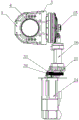
Fig. 3 is a front structural sectional view of the overall structure of the present invention.
Fig. 4 is a side structural sectional view of the overall structure of the present invention.
Fig. 5 is a top view structural cross-section of the overall structure of the present invention.
Fig. 6 is a structural sectional view showing the side inclined state of the overall structure of the present invention.
Fig. 7 is a schematic view of a portion of the structure shown in fig. 6.
Fig. 8 is a schematic view of the structure of the rotating arm cover plate of the present invention.
The reference signs are: 1 a first crossed roller bearing, 2 a first bevel gear, 3 a first shell, 4 a first oil seal, 5 a rotating arm cover plate, 6 a rotating arm, 7 a second oil seal, 8 a second bevel gear, 9 a third bevel gear, 10 a second shell, 11 a shell cover plate, 12 a second crossed roller bearing, 13 a first deep groove ball bearing, 14 a second deep groove ball bearing, 15 a nut, 16 a fifth bevel gear, 17 a third oil seal, 18 a third deep groove ball bearing, 19 a fourth deep groove ball bearing, 20 a first bearing cover, 21 a first straight gear, 22 a first gasket, 23 a first screw, 24 a first servo motor, 25 a sixth bevel gear, 26 a fourth oil seal, 27 a fifth deep groove ball bearing, 28 a sixth deep groove ball bearing, 29 a second bearing cover, 30 a second straight gear, 31 a second gasket, 32 a second screw, 33 a first retaining ring, 34 a third straight gear, 35 a fourth straight gear, 36 a second servo motor, 37 a second retaining ring, 37 a straight gear, 38 a third housing, 39 a fourth housing, 40 a fourth bevel gear, 41 a gasket.
Detailed Description
The technical solutions in the embodiments of the present invention will be clearly and completely described below with reference to the drawings in the embodiments of the present invention, and it is obvious that the described embodiments are only a part of the embodiments of the present invention, and not all of the embodiments. All other embodiments, which can be derived by a person skilled in the art from the embodiments given herein without making any creative effort, shall fall within the protection scope of the present invention.
1-8, the multi-level multi-faced hypoid bevel gear rotating mechanism comprises a first shell 3, a second shell 10, a third shell 38 and a fourth shell 39, wherein the first shell 3 is arranged at one side of the second shell 10, the third shell 38 and the fourth shell 39 are sequentially arranged at the bottom of the second shell 10, a transmission group A is arranged inside the first shell 3, a transmission group B is arranged inside the second shell 10, a power output part A and a power output part B are arranged inside the third shell 38, and a power input part A and a power input part B are arranged inside the fourth shell 39;
the transmission set A comprises a first crossed roller bearing 1, a first bevel gear 2 and first oil seals 4, wherein the first bevel gear 2 is arranged in a first shell 3, the first crossed roller bearing 1 is fixedly arranged on one side of the first shell 3, the number of the first oil seals 4 is two, and the two first oil seals 4 are fixedly arranged on the inner wall of the first crossed roller bearing 1 and in the other side of the first shell;
the transmission set B comprises a rotating arm 6, a second oil seal 7, a second bevel gear 8, a third bevel gear 9, a second crossed roller bearing 12, a first deep groove ball bearing 13, a second deep groove ball bearing 14, a fourth bevel gear 40 and a nut 15, wherein the fourth bevel gear 40 is arranged on one side, close to the first shell 3, of the second shell 10, the rotating arm 6, the second oil seal 7, the second bevel gear 8, the third bevel gear 9, the second crossed roller bearing 12, the first deep groove ball bearing 13, the second deep groove ball bearing 14 and the nut 15 are sequentially sleeved on the fourth bevel gear 40, and the nut 15 is used for fixing;
a rotating arm cover plate 5 is arranged between the first shell 3 and the second shell 10, the first shell 3 and the second shell 10 are connected through the rotating arm cover plate 5, the cross section of the rotating arm cover plate 5 is L-shaped, and the first bevel gear 2 is engaged with the fourth bevel gear 40.
Further, the power output part a comprises a fifth bevel gear 16, a third oil seal 17, a third deep groove ball bearing 18, a fourth deep groove ball bearing 19, a first bearing cover 20, a first straight gear 21, a first gasket 22 and a first screw 23, wherein the fifth bevel gear 16, the third oil seal 17, the third deep groove ball bearing 18, the fourth deep groove ball bearing 19, the first bearing cover 20, the first straight gear 21, the first gasket 22 and the first screw 23 are sequentially connected in series from top to bottom, wherein the first bearing cover 20 and the screw thereon fix the power output part a inside the third housing 38, and the fifth bevel gear 16 is meshed with the third bevel gear 9;
further, the power output part B comprises a sixth bevel gear 25, a fourth oil seal 26, a fifth deep groove ball bearing 27, a sixth deep groove ball bearing 28, a second bearing cover 29, a second spur gear 30, a second gasket 31 and a second screw 32, wherein the sixth bevel gear 25, the fourth oil seal 26, the fifth deep groove ball bearing 27, the sixth deep groove ball bearing 28, the second bearing cover 29, the second spur gear 30, the second gasket 31 and the second screw 32 are sequentially connected in series from top to bottom, the second bearing cover 29 and the screws thereon enable the power output part B to be fixed inside the third housing 38, and the sixth bevel gear 25 is meshed with the second bevel gear 8;
further, the power output part A and the power output part B are arranged side by side;
further, the power input part a includes a third spur gear 34, a first servo motor 24 and a first snap ring 33, the first snap ring 33 and the third spur gear 34 are sequentially and fixedly disposed on an output end of the first servo motor 24, the power input part B includes a fourth spur gear 35, a second servo motor 36 and a second snap ring 37, and the second snap ring 37 and the fourth spur gear 35 are sequentially and fixedly disposed on an output end of the second servo motor 36;
further, the power input part a and the power input part B are arranged side by side, the third spur gear 34 is engaged with the first spur gear 21, and the fourth spur gear 35 is engaged with the second spur gear 30;
further, a gasket 41 is disposed between the third housing 38 and the fourth housing 39, and a housing cover plate 11 is fixedly disposed on one side of the second housing 10.
A use method of a multi-level multi-surface hypoid bevel gear rotating mechanism comprises the following steps:
the method comprises the following steps: firstly, assembling a mechanism;
step two: assembling a first crossed roller bearing 1, a first bevel gear 2 and a first shell 3 together by screws, sealing two sides by a first oil seal 4, and completing the assembly of a transmission group A;
step three: sequentially sleeving a rotating arm 6, a second oil seal 7, a second bevel gear 8, a third bevel gear 9, a second crossed roller bearing 12, a first deep groove ball bearing 13 and a second deep groove ball bearing 14 on a fourth bevel gear 40, fixing by using a nut 15, and finishing the assembly of the transmission set B;
step four: fixing the first shell 3, the rotating arm cover plate 5, the second shell 10 and the shell cover plate 11 by screws;
step five: a fifth bevel gear 16, a third oil seal 17, a third deep groove ball bearing 18, a fourth deep groove ball bearing 19, a first bearing cover 20, a first straight gear 21, a first gasket 22 and a first screw 23 are sequentially connected in series from top to bottom, and then the power output part A is fixed in a third shell 38 through the first bearing cover 20 and the screw on the first bearing cover, so that the fifth bevel gear 16 is meshed with the third bevel gear 9, and the power output part A is assembled;
step six: a sixth bevel gear 25, a fourth oil seal 26, a fifth deep groove ball bearing 27, a sixth deep groove ball bearing 28, a second bearing cover 29, a second straight gear 30, a second gasket 31 and a second screw 32 are sequentially connected in series from top to bottom, and then the power output part B is fixed in a third shell 38 through the second bearing cover 29 and the screws on the second bearing cover, so that the power output part B is assembled;
step seven: a first snap ring 33 and a third spur gear 34 are sequentially fixedly arranged on the output end of the first servo motor 24 to form a power input part A;
step eight: a second retaining ring 37 and a fourth spur gear 35 are sequentially and fixedly arranged on the output end of a second servo motor 36 to form a power input part B, the power input part A and the power input part B are fixedly arranged in parallel inside a fourth shell 39, the third spur gear 34 is meshed with the first spur gear 21, the fourth spur gear 35 is meshed with the second spur gear 30, a sealing gasket 41 is arranged between the third shell 38 and the fourth shell 39, and the third shell 38 and the fourth shell 39 are fixed through screws;
step nine: thus, the whole mechanism is assembled;
step ten: the transmission group A, the rotating arm cover plate 5 and the rotating arm 6 jointly form a rotating structure N, and the inner ring of the first crossed roller bearing 1 is of a rotating structure M;
step eleven: the first straight gear 21 is driven to run by the first servo motor 24 through the third straight gear 34, and is linked with the fifth bevel gear 16, then drives the third bevel gear 9 to run, is linked with the fourth bevel gear 40, then drives the first bevel gear 2 to run, and is linked with the inner ring of the first crossed roller bearing 1, and the second-stage 360-degree rotating mechanism is formed;
step twelve: the second servo motor 36 drives the second straight gear 30 to operate through the fourth straight gear 35, and is linked with the sixth bevel gear 25, and then drives the second bevel gear 8 to operate, and is linked with the rotating structure N, which is a first-stage 360-degree rotating mechanism;
step thirteen: the second-stage 360-degree rotating mechanism is driven by the first servo motor 24 and can independently operate, when the first-stage 360-degree rotating mechanism rotates, the rotating structure N rotates around the fourth bevel gear 40 in a circular mode, at the moment, due to the fact that the first bevel gear 2 is meshed with the fourth bevel gear 40, when the rotating structure N rotates, the first bevel gear 2 interferes with the fourth bevel gear 40 and the rotating structure N is prevented from rotating, at the moment, the second servo motor 36 must be driven to operate, the fourth bevel gear 40 is linked to operate, and therefore the first bevel gear 2 and the rotating mechanism N are guaranteed to rotate around the fourth bevel gear 40 by 360 degrees.
The working principle of the invention is as follows:
referring to the attached drawings 1-8 of the specification, a first crossed roller bearing 1, a first bevel gear 2 and a first shell 3 are assembled together by screws, two sides are sealed by a first oil seal 4, a transmission set A is assembled, a rotating arm 6, a second oil seal 7, a second bevel gear 8, a third bevel gear 9, a second crossed roller bearing 12, a first deep groove ball bearing 13 and a second deep groove ball bearing 14 are sequentially sleeved on a fourth bevel gear 40 and fixed by a nut 15, a transmission set B is assembled, the first shell 3, the rotating arm cover plate 5, the second shell 10 and a shell cover plate 11 are fixed by screws, a fifth bevel gear 16, a third oil seal 17, a third deep groove ball bearing 18, a fourth deep groove ball bearing 19, a first bearing cover 20, a first straight gear 21, a first gasket 22 and a first screw 23 are sequentially connected in series from top to bottom and then a power output part A is fixed inside a third shell 38 by the first bearing cover 20 and the screw on the first bearing cover, the fifth bevel gear 16 is engaged with the third bevel gear 9, the power output part A is assembled, the sixth bevel gear 25, the fourth oil seal 26, the fifth deep groove ball bearing 27, the sixth deep groove ball bearing 28, the second bearing cap 29, the second spur gear 30, the second gasket 31 and the second screw 32 are sequentially connected in series from top to bottom, and then the power output part B is fixed inside the third housing 38 through the second bearing cap 29 and the screw thereon, the sixth bevel gear 25 is engaged with the second bevel gear 8, the power output part B is assembled, the first snap ring 33 and the third spur gear 34 are sequentially fixed on the output end of the first servomotor 24 to form the power input part A, the second snap ring 37 and the fourth spur gear 35 are sequentially fixed on the output end of the second servomotor 36 to form the power input part B, the power input part A and the power input part B are fixedly arranged inside the fourth housing 39 side by side, the third spur gear 34 is engaged with the first spur gear 21, the fourth spur gear 35 is engaged with the second spur gear 30, and the gasket 41 is provided between the third housing 38 and the fourth housing 39, and the third housing 38 and the fourth housing 39 are fixed by screws, and the assembly of the entire mechanism is completed;
referring to the attached drawings 1-8 of the specification, a second servo motor 36 drives a second straight gear 30 to operate through a fourth straight gear 35, and is linked with a sixth bevel gear 25, and then drives a second bevel gear 8 to operate, and is linked with a rotating structure N, which is a first-stage 360-degree rotating mechanism, the first servo motor 24 drives a first straight gear 21 to operate through a third straight gear 34, is linked with a fifth bevel gear 16, and is driven to operate through a third bevel gear 9, and is linked with a fourth bevel gear 40, and then drives a first bevel gear 2 to operate, and is linked with an inner ring of a first crossed roller bearing 1, which is a second-stage 360-degree rotating mechanism, and is driven by the first servo motor 24 to operate independently, when the first-stage 360-degree rotating mechanism rotates, the rotating structure N rotates around the fourth bevel gear 40, at this time, because the first bevel gear 2 is meshed with the fourth bevel gear 40, when the rotating structure N rotates, the first bevel gear 2 interferes with the fourth bevel gear 40 and prevents the rotating structure N from rotating, and the second servo motor 36 must be driven to operate to be linked with the fourth bevel gear 40 to ensure that the first bevel gear 2 and the rotating structure N rotate together by 360 ° around the fourth bevel gear 40.
The points to be finally explained are: first, in the description of the present application, it should be noted that, unless otherwise specified and limited, the terms "mounted," "connected," and "connected" should be understood broadly, and may be a mechanical connection or an electrical connection, or a communication between two elements, and may be a direct connection, and "upper," "lower," "left," and "right" are only used to indicate a relative positional relationship, and when the absolute position of the object to be described is changed, the relative positional relationship may be changed;
secondly, the method comprises the following steps: in the drawings of the disclosed embodiments of the invention, only the structures related to the disclosed embodiments are referred to, other structures can refer to common designs, and the same embodiment and different embodiments of the invention can be combined with each other without conflict;
and finally: the above description is only for the purpose of illustrating the preferred embodiments of the present invention and is not to be construed as limiting the invention, and any modifications, equivalents, improvements and the like that are within the spirit and principle of the present invention are intended to be included in the scope of the present invention.
Claims (8)
1. A multi-level multi-faced hypoid bevel gear rotating mechanism, comprising a first housing (3), a second housing (10), a third housing (38) and a fourth housing (39), characterized in that: the power transmission device comprises a first shell (3), a third shell (38) and a fourth shell (39), wherein the first shell (3) is arranged on one side of a second shell (10), the third shell (38) and the fourth shell (39) are sequentially arranged at the bottom of the second shell (10), a transmission group A is arranged in the first shell (3), a transmission group B is arranged in the second shell (10), a power output part A and a power output part B are arranged in the third shell (38), and a power input part A and a power input part B are arranged in the fourth shell (39);
the transmission set A comprises a first crossed roller bearing (1), a first bevel gear (2) and first oil seals (4), wherein the first bevel gear (2) is arranged in a first shell (3), the first crossed roller bearing (1) is fixedly arranged on one side of the first shell (3), the number of the first oil seals (4) is two, and the two first oil seals (4) are fixedly arranged on the inner wall of the first crossed roller bearing (1) and in the other side of the shell;
the transmission set B comprises a rotating arm (6), a second oil seal (7), a second bevel gear (8), a third bevel gear (9), a second crossed roller bearing (12), a first deep groove ball bearing (13), a second deep groove ball bearing (14), a fourth bevel gear (40) and a nut (15), wherein the fourth bevel gear (40) is arranged on one side, close to the first shell (3), of the second shell (10), the rotating arm (6), the second oil seal (7), the second bevel gear (8), the third bevel gear (9), the second crossed roller bearing (12), the first deep groove ball bearing (13), the second deep groove ball bearing (14) and the nut (15) are sequentially sleeved on the fourth bevel gear (40), and the nut (15) is used for fixing;
a rotating arm cover plate (5) is arranged between the first shell (3) and the second shell (10), the first shell (3) and the second shell (10) are connected through the rotating arm cover plate (5), the cross section of the rotating arm cover plate (5) is L-shaped, and the first bevel gear (2) is meshed with the fourth bevel gear (40).
2. The multi-level multi-faced hypoid bevel gear rotating mechanism according to claim 1, wherein: the power output part A comprises a fifth bevel gear (16), a third oil seal (17), a third deep groove ball bearing (18), a fourth deep groove ball bearing (19), a first bearing cover (20), a first straight gear (21), a first gasket (22) and a first screw (23), wherein the fifth bevel gear (16), the third oil seal (17), the third deep groove ball bearing (18), the fourth deep groove ball bearing (19), the first bearing cover (20), the first straight gear (21), the first gasket (22) and the first screw (23) are sequentially connected in series from top to bottom, the first bearing cover (20) and the screw on the first bearing cover fix the power output part A inside a third shell (38), and the fifth bevel gear (16) is meshed with the third bevel gear (9).
3. The multi-level multi-faced hypoid bevel gear rotating mechanism according to claim 1, wherein: power take off portion B includes sixth bevel gear (25), fourth oil blanket (26), fifth deep groove ball bearing (27), sixth deep groove ball bearing (28), second bearing cap (29), second spur gear (30), second gasket (31) and second screw (32), sixth bevel gear (25), fourth oil blanket (26), fifth deep groove ball bearing (27), sixth deep groove ball bearing (28), second bearing cap (29), second spur gear (30), second gasket (31) and second screw (32) establish ties from the top down in proper order, and wherein second bearing cap (29) and the screw above it make power take off portion B fix inside third shell (38), sixth bevel gear (25) mesh with second bevel gear (8) mutually.
4. The multi-level multi-faced hypoid bevel gear rotating mechanism according to claim 1, wherein: the power output part A and the power output part B are arranged side by side.
5. The multi-level multi-faced hypoid bevel gear rotating mechanism according to claim 1, wherein: power input portion A includes third straight-tooth gear (34), first servo motor (24) and first buckle (33), first buckle (33) and third straight-tooth gear (34) are fixed the setting in proper order on the output of first servo motor (24), power input portion B includes fourth straight-tooth gear (35), second servo motor (36) and second buckle (37), second buckle (37) and fourth straight-tooth gear (35) are fixed the setting in proper order on the output of second servo motor (36).
6. The multi-level multi-faced hypoid bevel gear rotating mechanism according to claim 1, wherein: the power input part A and the power input part B are arranged side by side, the third straight gear (34) is meshed with the first straight gear (21), and the fourth straight gear (35) is meshed with the second straight gear (30).
7. The multi-level multi-faced hypoid bevel gear rotating mechanism according to claim 1, wherein: a sealing gasket (41) is arranged between the third shell (38) and the fourth shell (39), and a shell cover plate (11) is fixedly arranged on one side of the second shell (10).
8. A use method of a multi-level multi-surface hypoid bevel gear rotating mechanism is characterized in that: the method comprises the following steps:
the method comprises the following steps: firstly, assembling a mechanism;
step two: assembling a first crossed roller bearing (1), a first bevel gear (2) and a first shell (3) together by screws, sealing two sides by a first oil seal (4), and completing the assembly of a transmission group A;
step three: sequentially sleeving a rotating arm (6), a second oil seal (7), a second bevel gear (8), a third bevel gear (9), a second crossed roller bearing (12), a first deep groove ball bearing (13) and a second deep groove ball bearing (14) on a fourth bevel gear (40), fixing by using a nut (15), and finishing the assembly of a transmission set B;
step four: fixing a first shell (3), a rotating arm cover plate (5), a second shell (10) and a shell cover plate (11) by screws;
step five: a fifth bevel gear (16), a third oil seal (17), a third deep groove ball bearing (18), a fourth deep groove ball bearing (19), a first bearing gland (20), a first straight gear (21), a first gasket (22) and a first screw (23) are sequentially connected in series from top to bottom and then pass through the first bearing gland (20) and the screw on the first bearing gland, so that a power output part A is fixed inside a third shell (38), the fifth bevel gear (16) is meshed with a third bevel gear (9), and the power output part A is assembled;
step six: a sixth bevel gear (25), a fourth oil seal (26), a fifth deep groove ball bearing (27), a sixth deep groove ball bearing (28), a second bearing cap (29), a second straight gear (30), a second gasket (31) and a second screw (32) are sequentially connected in series from top to bottom and then pass through the second bearing cap (29) and the screw on the second bearing cap, so that a power output part B is fixed inside a third shell (38), the sixth bevel gear (25) is meshed with the second bevel gear (8), and the power output part B is assembled;
step seven: a first snap ring (33) and a third straight gear (34) are sequentially and fixedly arranged on the output end of the first servo motor (24) to form a power input part A;
step eight: a second retaining ring (37) and a fourth straight gear (35) are sequentially and fixedly arranged on the output end of a second servo motor (36) to form a power input part B, the power input part A and the power input part B are fixedly arranged in a fourth shell (39) side by side, the third straight gear (34) is meshed with the first straight gear (21), the fourth straight gear (35) is meshed with the second straight gear (30), a sealing gasket (41) is arranged between the third shell (38) and the fourth shell (39), and the third shell (38) and the fourth shell (39) are fixed through screws;
step nine: thus, the whole mechanism is assembled;
step ten: the transmission group A, the rotating arm cover plate (5) and the rotating arm (6) jointly form a rotating structure N, and the inner ring of the first crossed roller bearing (1) is of a rotating structure M;
step eleven: a first straight gear (21) is driven to operate by a first servo motor (24) through a third straight gear (34), and is linked with a fifth bevel gear (16), then a third bevel gear (9) is driven to operate, and is linked with a fourth bevel gear (40), then a first bevel gear (2) is driven to operate, and is linked with an inner ring of a first crossed roller bearing (1), and the inner ring is a second-stage 360-degree rotating mechanism;
step twelve: a second servo motor (36) drives a second straight gear (30) to operate through a fourth straight gear (35), and is linked with a sixth bevel gear (25) to drive a second bevel gear (8) to operate, and is linked with a rotating structure N which is a first-stage 360-degree rotating mechanism;
step thirteen: the second-stage 360-degree rotating mechanism is driven by the first servo motor (24) and can independently operate, when the first-stage 360-degree rotating mechanism rotates, the rotating structure N rotates around the fourth bevel gear (40) in a circular mode, at the moment, due to the fact that the first bevel gear (2) is meshed with the fourth bevel gear (40), when the rotating structure N rotates, the first bevel gear (2) and the fourth bevel gear (40) can interfere with each other and prevent the rotating structure N from rotating, at the moment, the second servo motor (36) must be driven to operate, the fourth bevel gear (40) is linked to operate, and therefore the first bevel gear (2) and the rotating mechanism N are enabled to rotate around the fourth bevel gear (40) in a 360-degree mode.
Priority Applications (1)
| Application Number | Priority Date | Filing Date | Title |
|---|---|---|---|
| CN201911114554.3A CN110701250A (en) | 2019-11-14 | 2019-11-14 | Multi-layer multi-surface hypoid bevel gear rotating mechanism and using method thereof |
Applications Claiming Priority (1)
| Application Number | Priority Date | Filing Date | Title |
|---|---|---|---|
| CN201911114554.3A CN110701250A (en) | 2019-11-14 | 2019-11-14 | Multi-layer multi-surface hypoid bevel gear rotating mechanism and using method thereof |
Publications (1)
| Publication Number | Publication Date |
|---|---|
| CN110701250A true CN110701250A (en) | 2020-01-17 |
Family
ID=69204390
Family Applications (1)
| Application Number | Title | Priority Date | Filing Date |
|---|---|---|---|
| CN201911114554.3A Pending CN110701250A (en) | 2019-11-14 | 2019-11-14 | Multi-layer multi-surface hypoid bevel gear rotating mechanism and using method thereof |
Country Status (1)
| Country | Link |
|---|---|
| CN (1) | CN110701250A (en) |
Citations (5)
| Publication number | Priority date | Publication date | Assignee | Title |
|---|---|---|---|---|
| CN101881320A (en) * | 2009-05-08 | 2010-11-10 | 湖南省双峰县湘源皇视电子有限公司 | Multi-output shaft gearbox with different rotating speeds |
| CN202726933U (en) * | 2012-08-01 | 2013-02-13 | 成都佳士科技有限公司 | Wrist transmission structure of manipulator |
| CN102966701A (en) * | 2012-11-21 | 2013-03-13 | 中国船舶重工集团公司第七一六研究所 | Hypoid bevel gear transmission device |
| JP2017106533A (en) * | 2015-12-09 | 2017-06-15 | 株式会社安川電機 | Actuator |
| CN211039540U (en) * | 2019-11-14 | 2020-07-17 | 常熟鑫利茗动力科技有限公司 | Multi-layer multi-surface hypoid bevel gear rotating mechanism |
-
2019
- 2019-11-14 CN CN201911114554.3A patent/CN110701250A/en active Pending
Patent Citations (5)
| Publication number | Priority date | Publication date | Assignee | Title |
|---|---|---|---|---|
| CN101881320A (en) * | 2009-05-08 | 2010-11-10 | 湖南省双峰县湘源皇视电子有限公司 | Multi-output shaft gearbox with different rotating speeds |
| CN202726933U (en) * | 2012-08-01 | 2013-02-13 | 成都佳士科技有限公司 | Wrist transmission structure of manipulator |
| CN102966701A (en) * | 2012-11-21 | 2013-03-13 | 中国船舶重工集团公司第七一六研究所 | Hypoid bevel gear transmission device |
| JP2017106533A (en) * | 2015-12-09 | 2017-06-15 | 株式会社安川電機 | Actuator |
| CN211039540U (en) * | 2019-11-14 | 2020-07-17 | 常熟鑫利茗动力科技有限公司 | Multi-layer multi-surface hypoid bevel gear rotating mechanism |
Similar Documents
| Publication | Publication Date | Title |
|---|---|---|
| US11078989B2 (en) | Reduction gear and electromechanical device | |
| JP2011237026A (en) | Planetary gear speed reducer | |
| CN107842590B (en) | Redundancy angular displacement output type differential mechanism | |
| CN211039540U (en) | Multi-layer multi-surface hypoid bevel gear rotating mechanism | |
| KR101171810B1 (en) | Manipulator with an external rotor motor | |
| JP2866249B2 (en) | Speed reducer series with internal meshing planetary gear structure | |
| CN214274369U (en) | Motor with novel tooth difference planet wheel gear box | |
| CN113843776A (en) | Modularization executor, arm and robot | |
| CN110701250A (en) | Multi-layer multi-surface hypoid bevel gear rotating mechanism and using method thereof | |
| JP2017040348A (en) | Planetary gear device and its design method | |
| JP2004197921A (en) | Hypoid reduction gear unit and its series | |
| CA2954108C (en) | Planetary gear assembly | |
| CN214274368U (en) | Motor with built-in gear difference planetary gear box | |
| CN102261432B (en) | Planet gear speed reducing mechanism and motor | |
| CN115000677A (en) | Dual-input antenna unfolding driving device | |
| CN209100607U (en) | A kind of driving speed reducer of ultra-large type hydraulic crawler excavator | |
| CN107701667B (en) | Composite speed reducer | |
| KR20110121127A (en) | A reduction gear of cycloid | |
| CN205047749U (en) | Planetary gear drive mechanism | |
| CN110836223A (en) | Crossed roller bearing and speed reducer | |
| CN219605976U (en) | Differential planetary reducer | |
| CN210240456U (en) | Planetary reducer with stable structure | |
| KR101941539B1 (en) | Planetary gear reducer | |
| CN216180508U (en) | Modularization executor, arm and robot | |
| CN211145102U (en) | Crossed roller bearing and speed reducer |
Legal Events
| Date | Code | Title | Description |
|---|---|---|---|
| PB01 | Publication | ||
| PB01 | Publication | ||
| SE01 | Entry into force of request for substantive examination | ||
| SE01 | Entry into force of request for substantive examination | ||
| RJ01 | Rejection of invention patent application after publication | ||
| RJ01 | Rejection of invention patent application after publication |
Application publication date: 20200117 |