RU2638897C2 - Method of multiphase pump operation and its arrangement - Google Patents
Method of multiphase pump operation and its arrangement Download PDFInfo
- Publication number
- RU2638897C2 RU2638897C2 RU2014152045A RU2014152045A RU2638897C2 RU 2638897 C2 RU2638897 C2 RU 2638897C2 RU 2014152045 A RU2014152045 A RU 2014152045A RU 2014152045 A RU2014152045 A RU 2014152045A RU 2638897 C2 RU2638897 C2 RU 2638897C2
- Authority
- RU
- Russia
- Prior art keywords
- liquid phase
- phase
- separator
- separated
- chamber
- Prior art date
Links
- 238000000034 method Methods 0.000 title claims abstract description 36
- 239000007791 liquid phase Substances 0.000 claims abstract description 104
- 239000007790 solid phase Substances 0.000 claims abstract description 70
- 239000000203 mixture Substances 0.000 claims abstract description 46
- 239000007792 gaseous phase Substances 0.000 claims abstract description 32
- 239000007787 solid Substances 0.000 claims abstract description 28
- 239000002245 particle Substances 0.000 claims abstract description 19
- 238000005086 pumping Methods 0.000 claims abstract description 12
- 239000010802 sludge Substances 0.000 claims description 43
- 230000007246 mechanism Effects 0.000 claims description 41
- 238000000926 separation method Methods 0.000 claims description 28
- 239000007789 gas Substances 0.000 claims description 21
- 239000007788 liquid Substances 0.000 claims description 19
- 238000002347 injection Methods 0.000 claims description 5
- 239000007924 injection Substances 0.000 claims description 5
- 239000013049 sediment Substances 0.000 claims description 4
- 238000007689 inspection Methods 0.000 claims description 3
- 230000001105 regulatory effect Effects 0.000 claims description 2
- 239000000126 substance Substances 0.000 abstract description 3
- 230000008569 process Effects 0.000 description 13
- 239000012071 phase Substances 0.000 description 10
- 230000007423 decrease Effects 0.000 description 7
- 238000004519 manufacturing process Methods 0.000 description 6
- 230000005484 gravity Effects 0.000 description 5
- 230000015572 biosynthetic process Effects 0.000 description 4
- 238000013461 design Methods 0.000 description 4
- 239000012530 fluid Substances 0.000 description 4
- 238000005755 formation reaction Methods 0.000 description 4
- 229930195733 hydrocarbon Natural products 0.000 description 4
- 150000002430 hydrocarbons Chemical class 0.000 description 4
- 238000011144 upstream manufacturing Methods 0.000 description 4
- 238000005461 lubrication Methods 0.000 description 3
- 230000009471 action Effects 0.000 description 2
- 238000013459 approach Methods 0.000 description 2
- 230000004888 barrier function Effects 0.000 description 2
- 230000006835 compression Effects 0.000 description 2
- 238000007906 compression Methods 0.000 description 2
- 238000010438 heat treatment Methods 0.000 description 2
- 239000003112 inhibitor Substances 0.000 description 2
- VNWKTOKETHGBQD-UHFFFAOYSA-N methane Chemical compound C VNWKTOKETHGBQD-UHFFFAOYSA-N 0.000 description 2
- 238000005192 partition Methods 0.000 description 2
- 230000000737 periodic effect Effects 0.000 description 2
- 239000002244 precipitate Substances 0.000 description 2
- 230000008439 repair process Effects 0.000 description 2
- 230000000717 retained effect Effects 0.000 description 2
- 230000002411 adverse Effects 0.000 description 1
- 230000001174 ascending effect Effects 0.000 description 1
- 238000005452 bending Methods 0.000 description 1
- 230000008901 benefit Effects 0.000 description 1
- 230000001276 controlling effect Effects 0.000 description 1
- 238000001816 cooling Methods 0.000 description 1
- 238000010586 diagram Methods 0.000 description 1
- 238000001914 filtration Methods 0.000 description 1
- 230000017525 heat dissipation Effects 0.000 description 1
- 239000012535 impurity Substances 0.000 description 1
- 238000012423 maintenance Methods 0.000 description 1
- 238000002156 mixing Methods 0.000 description 1
- 230000004048 modification Effects 0.000 description 1
- 238000012986 modification Methods 0.000 description 1
- 239000003345 natural gas Substances 0.000 description 1
- 230000035515 penetration Effects 0.000 description 1
- 230000035699 permeability Effects 0.000 description 1
- 230000008092 positive effect Effects 0.000 description 1
- 238000001556 precipitation Methods 0.000 description 1
- 238000012545 processing Methods 0.000 description 1
- 230000000630 rising effect Effects 0.000 description 1
- 239000011435 rock Substances 0.000 description 1
- 238000007789 sealing Methods 0.000 description 1
- 230000001960 triggered effect Effects 0.000 description 1
- XLYOFNOQVPJJNP-UHFFFAOYSA-N water Substances O XLYOFNOQVPJJNP-UHFFFAOYSA-N 0.000 description 1
Images
Classifications
-
- F—MECHANICAL ENGINEERING; LIGHTING; HEATING; WEAPONS; BLASTING
- F04—POSITIVE - DISPLACEMENT MACHINES FOR LIQUIDS; PUMPS FOR LIQUIDS OR ELASTIC FLUIDS
- F04C—ROTARY-PISTON, OR OSCILLATING-PISTON, POSITIVE-DISPLACEMENT MACHINES FOR LIQUIDS; ROTARY-PISTON, OR OSCILLATING-PISTON, POSITIVE-DISPLACEMENT PUMPS
- F04C13/00—Adaptations of machines or pumps for special use, e.g. for extremely high pressures
- F04C13/005—Removing contaminants, deposits or scale from the pump; Cleaning
-
- F—MECHANICAL ENGINEERING; LIGHTING; HEATING; WEAPONS; BLASTING
- F04—POSITIVE - DISPLACEMENT MACHINES FOR LIQUIDS; PUMPS FOR LIQUIDS OR ELASTIC FLUIDS
- F04C—ROTARY-PISTON, OR OSCILLATING-PISTON, POSITIVE-DISPLACEMENT MACHINES FOR LIQUIDS; ROTARY-PISTON, OR OSCILLATING-PISTON, POSITIVE-DISPLACEMENT PUMPS
- F04C13/00—Adaptations of machines or pumps for special use, e.g. for extremely high pressures
- F04C13/007—Venting; Gas and vapour separation during pumping
-
- B—PERFORMING OPERATIONS; TRANSPORTING
- B01—PHYSICAL OR CHEMICAL PROCESSES OR APPARATUS IN GENERAL
- B01D—SEPARATION
- B01D21/00—Separation of suspended solid particles from liquids by sedimentation
- B01D21/0018—Separation of suspended solid particles from liquids by sedimentation provided with a pump mounted in or on a settling tank
-
- B—PERFORMING OPERATIONS; TRANSPORTING
- B01—PHYSICAL OR CHEMICAL PROCESSES OR APPARATUS IN GENERAL
- B01D—SEPARATION
- B01D21/00—Separation of suspended solid particles from liquids by sedimentation
- B01D21/24—Feed or discharge mechanisms for settling tanks
- B01D21/2494—Feed or discharge mechanisms for settling tanks provided with means for the removal of gas, e.g. noxious gas, air
-
- B—PERFORMING OPERATIONS; TRANSPORTING
- B01—PHYSICAL OR CHEMICAL PROCESSES OR APPARATUS IN GENERAL
- B01D—SEPARATION
- B01D21/00—Separation of suspended solid particles from liquids by sedimentation
- B01D21/30—Control equipment
- B01D21/34—Controlling the feed distribution; Controlling the liquid level ; Control of process parameters
-
- B—PERFORMING OPERATIONS; TRANSPORTING
- B01—PHYSICAL OR CHEMICAL PROCESSES OR APPARATUS IN GENERAL
- B01D—SEPARATION
- B01D45/00—Separating dispersed particles from gases or vapours by gravity, inertia, or centrifugal forces
- B01D45/04—Separating dispersed particles from gases or vapours by gravity, inertia, or centrifugal forces by utilising inertia
- B01D45/08—Separating dispersed particles from gases or vapours by gravity, inertia, or centrifugal forces by utilising inertia by impingement against baffle separators
-
- B—PERFORMING OPERATIONS; TRANSPORTING
- B01—PHYSICAL OR CHEMICAL PROCESSES OR APPARATUS IN GENERAL
- B01D—SEPARATION
- B01D45/00—Separating dispersed particles from gases or vapours by gravity, inertia, or centrifugal forces
- B01D45/12—Separating dispersed particles from gases or vapours by gravity, inertia, or centrifugal forces by centrifugal forces
- B01D45/16—Separating dispersed particles from gases or vapours by gravity, inertia, or centrifugal forces by centrifugal forces generated by the winding course of the gas stream, the centrifugal forces being generated solely or partly by mechanical means, e.g. fixed swirl vanes
-
- F—MECHANICAL ENGINEERING; LIGHTING; HEATING; WEAPONS; BLASTING
- F04—POSITIVE - DISPLACEMENT MACHINES FOR LIQUIDS; PUMPS FOR LIQUIDS OR ELASTIC FLUIDS
- F04B—POSITIVE-DISPLACEMENT MACHINES FOR LIQUIDS; PUMPS
- F04B15/00—Pumps adapted to handle specific fluids, e.g. by selection of specific materials for pumps or pump parts
-
- F—MECHANICAL ENGINEERING; LIGHTING; HEATING; WEAPONS; BLASTING
- F04—POSITIVE - DISPLACEMENT MACHINES FOR LIQUIDS; PUMPS FOR LIQUIDS OR ELASTIC FLUIDS
- F04B—POSITIVE-DISPLACEMENT MACHINES FOR LIQUIDS; PUMPS
- F04B3/00—Machines or pumps with pistons coacting within one cylinder, e.g. multi-stage
-
- F—MECHANICAL ENGINEERING; LIGHTING; HEATING; WEAPONS; BLASTING
- F04—POSITIVE - DISPLACEMENT MACHINES FOR LIQUIDS; PUMPS FOR LIQUIDS OR ELASTIC FLUIDS
- F04C—ROTARY-PISTON, OR OSCILLATING-PISTON, POSITIVE-DISPLACEMENT MACHINES FOR LIQUIDS; ROTARY-PISTON, OR OSCILLATING-PISTON, POSITIVE-DISPLACEMENT PUMPS
- F04C11/00—Combinations of two or more machines or pumps, each being of rotary-piston or oscillating-piston type; Pumping installations
- F04C11/001—Combinations of two or more machines or pumps, each being of rotary-piston or oscillating-piston type; Pumping installations of similar working principle
-
- F—MECHANICAL ENGINEERING; LIGHTING; HEATING; WEAPONS; BLASTING
- F04—POSITIVE - DISPLACEMENT MACHINES FOR LIQUIDS; PUMPS FOR LIQUIDS OR ELASTIC FLUIDS
- F04C—ROTARY-PISTON, OR OSCILLATING-PISTON, POSITIVE-DISPLACEMENT MACHINES FOR LIQUIDS; ROTARY-PISTON, OR OSCILLATING-PISTON, POSITIVE-DISPLACEMENT PUMPS
- F04C13/00—Adaptations of machines or pumps for special use, e.g. for extremely high pressures
- F04C13/008—Pumps for submersible use, i.e. down-hole pumping
-
- F—MECHANICAL ENGINEERING; LIGHTING; HEATING; WEAPONS; BLASTING
- F04—POSITIVE - DISPLACEMENT MACHINES FOR LIQUIDS; PUMPS FOR LIQUIDS OR ELASTIC FLUIDS
- F04C—ROTARY-PISTON, OR OSCILLATING-PISTON, POSITIVE-DISPLACEMENT MACHINES FOR LIQUIDS; ROTARY-PISTON, OR OSCILLATING-PISTON, POSITIVE-DISPLACEMENT PUMPS
- F04C2/00—Rotary-piston machines or pumps
- F04C2/08—Rotary-piston machines or pumps of intermeshing-engagement type, i.e. with engagement of co-operating members similar to that of toothed gearing
- F04C2/10—Rotary-piston machines or pumps of intermeshing-engagement type, i.e. with engagement of co-operating members similar to that of toothed gearing of internal-axis type with the outer member having more teeth or tooth-equivalents, e.g. rollers, than the inner member
- F04C2/107—Rotary-piston machines or pumps of intermeshing-engagement type, i.e. with engagement of co-operating members similar to that of toothed gearing of internal-axis type with the outer member having more teeth or tooth-equivalents, e.g. rollers, than the inner member with helical teeth
-
- F—MECHANICAL ENGINEERING; LIGHTING; HEATING; WEAPONS; BLASTING
- F04—POSITIVE - DISPLACEMENT MACHINES FOR LIQUIDS; PUMPS FOR LIQUIDS OR ELASTIC FLUIDS
- F04C—ROTARY-PISTON, OR OSCILLATING-PISTON, POSITIVE-DISPLACEMENT MACHINES FOR LIQUIDS; ROTARY-PISTON, OR OSCILLATING-PISTON, POSITIVE-DISPLACEMENT PUMPS
- F04C3/00—Rotary-piston machines or pumps, with non-parallel axes of movement of co-operating members, e.g. of screw type
- F04C3/06—Rotary-piston machines or pumps, with non-parallel axes of movement of co-operating members, e.g. of screw type the axes being arranged otherwise than at an angle of 90 degrees
- F04C3/08—Rotary-piston machines or pumps, with non-parallel axes of movement of co-operating members, e.g. of screw type the axes being arranged otherwise than at an angle of 90 degrees of intermeshing engagement type, i.e. with engagement of co-operating members similar to that of toothed gearing
- F04C3/085—Rotary-piston machines or pumps, with non-parallel axes of movement of co-operating members, e.g. of screw type the axes being arranged otherwise than at an angle of 90 degrees of intermeshing engagement type, i.e. with engagement of co-operating members similar to that of toothed gearing the axes of cooperating members being on the same plane
-
- B—PERFORMING OPERATIONS; TRANSPORTING
- B04—CENTRIFUGAL APPARATUS OR MACHINES FOR CARRYING-OUT PHYSICAL OR CHEMICAL PROCESSES
- B04C—APPARATUS USING FREE VORTEX FLOW, e.g. CYCLONES
- B04C3/00—Apparatus in which the axial direction of the vortex flow following a screw-thread type line remains unchanged ; Devices in which one of the two discharge ducts returns centrally through the vortex chamber, a reverse-flow vortex being prevented by bulkheads in the central discharge duct
- B04C2003/006—Construction of elements by which the vortex flow is generated or degenerated
-
- B—PERFORMING OPERATIONS; TRANSPORTING
- B04—CENTRIFUGAL APPARATUS OR MACHINES FOR CARRYING-OUT PHYSICAL OR CHEMICAL PROCESSES
- B04C—APPARATUS USING FREE VORTEX FLOW, e.g. CYCLONES
- B04C3/00—Apparatus in which the axial direction of the vortex flow following a screw-thread type line remains unchanged ; Devices in which one of the two discharge ducts returns centrally through the vortex chamber, a reverse-flow vortex being prevented by bulkheads in the central discharge duct
- B04C3/06—Construction of inlets or outlets to the vortex chamber
-
- F—MECHANICAL ENGINEERING; LIGHTING; HEATING; WEAPONS; BLASTING
- F04—POSITIVE - DISPLACEMENT MACHINES FOR LIQUIDS; PUMPS FOR LIQUIDS OR ELASTIC FLUIDS
- F04C—ROTARY-PISTON, OR OSCILLATING-PISTON, POSITIVE-DISPLACEMENT MACHINES FOR LIQUIDS; ROTARY-PISTON, OR OSCILLATING-PISTON, POSITIVE-DISPLACEMENT PUMPS
- F04C13/00—Adaptations of machines or pumps for special use, e.g. for extremely high pressures
- F04C13/001—Pumps for particular liquids
-
- F—MECHANICAL ENGINEERING; LIGHTING; HEATING; WEAPONS; BLASTING
- F04—POSITIVE - DISPLACEMENT MACHINES FOR LIQUIDS; PUMPS FOR LIQUIDS OR ELASTIC FLUIDS
- F04C—ROTARY-PISTON, OR OSCILLATING-PISTON, POSITIVE-DISPLACEMENT MACHINES FOR LIQUIDS; ROTARY-PISTON, OR OSCILLATING-PISTON, POSITIVE-DISPLACEMENT PUMPS
- F04C15/00—Component parts, details or accessories of machines, pumps or pumping installations, not provided for in groups F04C2/00 - F04C14/00
- F04C15/06—Arrangements for admission or discharge of the working fluid, e.g. constructional features of the inlet or outlet
-
- F—MECHANICAL ENGINEERING; LIGHTING; HEATING; WEAPONS; BLASTING
- F04—POSITIVE - DISPLACEMENT MACHINES FOR LIQUIDS; PUMPS FOR LIQUIDS OR ELASTIC FLUIDS
- F04C—ROTARY-PISTON, OR OSCILLATING-PISTON, POSITIVE-DISPLACEMENT MACHINES FOR LIQUIDS; ROTARY-PISTON, OR OSCILLATING-PISTON, POSITIVE-DISPLACEMENT PUMPS
- F04C2/00—Rotary-piston machines or pumps
- F04C2/08—Rotary-piston machines or pumps of intermeshing-engagement type, i.e. with engagement of co-operating members similar to that of toothed gearing
- F04C2/12—Rotary-piston machines or pumps of intermeshing-engagement type, i.e. with engagement of co-operating members similar to that of toothed gearing of other than internal-axis type
- F04C2/14—Rotary-piston machines or pumps of intermeshing-engagement type, i.e. with engagement of co-operating members similar to that of toothed gearing of other than internal-axis type with toothed rotary pistons
- F04C2/16—Rotary-piston machines or pumps of intermeshing-engagement type, i.e. with engagement of co-operating members similar to that of toothed gearing of other than internal-axis type with toothed rotary pistons with helical teeth, e.g. chevron-shaped, screw type
-
- F—MECHANICAL ENGINEERING; LIGHTING; HEATING; WEAPONS; BLASTING
- F04—POSITIVE - DISPLACEMENT MACHINES FOR LIQUIDS; PUMPS FOR LIQUIDS OR ELASTIC FLUIDS
- F04C—ROTARY-PISTON, OR OSCILLATING-PISTON, POSITIVE-DISPLACEMENT MACHINES FOR LIQUIDS; ROTARY-PISTON, OR OSCILLATING-PISTON, POSITIVE-DISPLACEMENT PUMPS
- F04C2210/00—Fluid
- F04C2210/24—Fluid mixed, e.g. two-phase fluid
-
- F—MECHANICAL ENGINEERING; LIGHTING; HEATING; WEAPONS; BLASTING
- F04—POSITIVE - DISPLACEMENT MACHINES FOR LIQUIDS; PUMPS FOR LIQUIDS OR ELASTIC FLUIDS
- F04C—ROTARY-PISTON, OR OSCILLATING-PISTON, POSITIVE-DISPLACEMENT MACHINES FOR LIQUIDS; ROTARY-PISTON, OR OSCILLATING-PISTON, POSITIVE-DISPLACEMENT PUMPS
- F04C2240/00—Components
- F04C2240/80—Other components
- F04C2240/806—Pipes for fluids; Fittings therefor
Abstract
Description
Данное изобретение касается способа работы многофазного насоса с впускным отверстием (подводом) со стороны всасывания и выходным отверстием (отводом) с напорной (разгрузочной) стороны, который нагнетает многофазную смесь с твердыми частицами. Изобретение также касается работы устройств прокачки многофазной смеси с содержанием твердых частиц, работа которых предполагает использование многофазного насоса с впускным отверстием (подводом) со стороны всасывания и выходным отверстием (отводом) с разгрузочной стороны. Под процессом разделения (сепарации) с разгрузочной стороны понимается, что жидкая фаза отделяется от газообразной фазы и по линии рециркуляции сепарированная жидкая фаза перемещается на сторону всасывания.This invention relates to a method of operating a multiphase pump with an inlet (inlet) on the suction side and an outlet (outlet) on the pressure (discharge) side, which pumps a multiphase mixture with solid particles. The invention also relates to the operation of devices for pumping a multiphase mixture with a solids content, the operation of which involves the use of a multiphase pump with an inlet (inlet) on the suction side and an outlet (outlet) on the discharge side. The process of separation (separation) from the discharge side is understood that the liquid phase is separated from the gaseous phase and the separated liquid phase is moved to the suction side along the recirculation line.
В частности, вышеуказанное имеет непосредственное отношение к добыче углеводородов (а точнее к добыче нефти и природного газа), к смесям веществ с крайне неоднородным составом. Это могут быть как скважины с исключительно газовым компонентом, так и скважины со 100% жидким компонентом. Спрогнозировать длительность отдельных фаз при добыче или состав многофазных смесей не представляется возможным. В принципе, можно отделить разные фазы друг от друга до прокачки многофазной смеси, т.е. отделить в сепараторе друг от друга газовую фазу и жидкую фазу таким образом, чтобы только газовая фаза или только жидкая фаза поступала на соответствующие насосные установки. Такой способ подразумевает большие производственные и транспортные затраты.In particular, the above is directly related to the production of hydrocarbons (and more specifically to the production of oil and natural gas), to mixtures of substances with an extremely heterogeneous composition. These can be either wells with an exclusively gas component or wells with a 100% liquid component. It is not possible to predict the duration of individual phases during production or the composition of multiphase mixtures. In principle, it is possible to separate the different phases from each other before pumping the multiphase mixture, i.e. separate the gas phase and the liquid phase in the separator from each other so that only the gas phase or only the liquid phase enters the respective pumping units. This method involves large production and transportation costs.
Чтобы избежать расходов на приобретение такого сепаратора, как правило, используют многофазный насос, суть работы которого заключается в использовании многошпиндельного винтового насосного устройства.To avoid the cost of acquiring such a separator, as a rule, a multiphase pump is used, the essence of which is to use a multi-spindle screw pump device.
Режим работы многофазного винтового насоса и насоса с, по меньшей мере, одним винтовым шпинделем известен под номером WO 94/27049 A1. Корпус имеет, по меньшей мере, один всасывающий патрубок и, по меньшей мере, один разгрузочный патрубок. Входящая масса подается параллельно на винтовой шпиндель непрерывным мало-импульсным потоком и беспрерывно выводится на разгрузочный патрубок. Процесс отделения (сепарации) жидкой фазы от газообразной фазы происходит в напорной камере. На разгрузочной стороне часть жидкости сепарированной жидкой фазы перекачивается в зону всасывания, рециркулируется, и, таким образом, в процессе циркуляции обеспечивает уплотнение и охлаждение. В результате раздела (сепарации) скорость потока выходной массы на разгрузочной стороне снижается. Жидкостная обводная линия расположена в напорной камере на глубине, достаточной для обеспечения постоянной циркуляции жидкости. Соединение обводной линии расположено под корпусом насоса.The operating mode of the multiphase screw pump and pump with at least one screw spindle is known as WO 94/27049 A1. The housing has at least one suction pipe and at least one discharge pipe. The incoming mass is fed in parallel to the screw spindle in a continuous low-pulse flow and is continuously output to the discharge pipe. The process of separation (separation) of the liquid phase from the gaseous phase occurs in the pressure chamber. On the discharge side, a portion of the liquid of the separated liquid phase is pumped to the suction zone, recycled, and thus provides sealing and cooling during the circulation process. As a result of separation (separation), the flow rate of the output mass on the discharge side is reduced. The liquid bypass line is located in the pressure chamber at a depth sufficient to ensure constant fluid circulation. The bypass connection is located under the pump housing.
В результате повышения спроса на углеводороды, кроме прочего, увеличилась добыча в легкодоступных и нефтегазоносных (продуктивных) местах. Поэтому скважины, которые являются менее продуктивными или имеют большую долю твердой фазы в многофазной смеси, стали использоваться более интенсивно. Кроме того, были предприняты попытки продлить срок эксплуатации скважин, которые были вскрыты при помощи гидроразрыва пласта (фрекинга), что позволило в результате образования трещин увеличить общую газовую и жидкостную проходимость в скалистых породах. Это также привело к увеличению содержания твердых частиц в прокачиваемой многофазной смеси.As a result of increased demand for hydrocarbons, among other things, production increased in easily accessible and oil-and-gas-bearing (productive) places. Therefore, wells that are less productive or have a large fraction of the solid phase in the multiphase mixture, began to be used more intensively. In addition, attempts were made to extend the life of wells that were discovered by hydraulic fracturing (fracking), which allowed the formation of cracks to increase the total gas and liquid permeability in rock formations. This also led to an increase in the solids content of the pumped multiphase mixture.
При увеличении содержания твердых частиц у оборудования с определенным уровнем технической оснащенности (prior art device) возникают проблемы, связанные с глубоким расположением линии рециркуляции, так как попадающие на дно твердые частицы в зоне пониженного потока также рециркулируются, что ведет к повышенному износу винтов и корпуса насоса. Кроме того, существует риск того, что линия рециркуляции будет закупорена такими твердыми веществами.With an increase in the solids content of equipment with a certain level of technical equipment (prior art device), problems arise due to the deep location of the recirculation line, since solids falling to the bottom in the low-flow zone are also recycled, which leads to increased wear of the screws and pump housing . In addition, there is a risk that the recirculation line will become clogged with such solids.
Цель этого изобретения заключается в рассмотрении способа и механизма снижения или устранения таких неблагоприятных факторов. В соответствии с изобретением, эта цель достигается с помощью способа, имеющего характерные черты главного пункта формулы изобретения, и устройства, имеющего характеристики подчиненного пункта формулы изобретения. Приоритетные конфигурации и дополнительные способы реализации этого изобретения раскрыты в дополнительных пунктах формулы изобретения, описаниях и чертежах.The purpose of this invention is to consider a method and mechanism for reducing or eliminating such adverse factors. In accordance with the invention, this goal is achieved using a method having the characteristic features of the main claim, and a device having the characteristics of a subordinate claim. Priority configurations and additional methods for implementing this invention are disclosed in additional claims, descriptions and drawings.
В изобретении предлагается способ работы многофазного насоса, у которого есть впускное отверстие (подвод, патрубок) со стороны всасывания и выходное отверстие с разгрузочной стороны. Насос закачивает внутрь многофазную смесь с твердыми частицами, которая прокачивается в сепараторную камеру с разгрузочной стороны. Затем в этой камере газообразная фаза отделяется от жидкой и твердой фазы. После чего жидкая фаза отделяется там же от твердой фазы, и часть жидкой фазы (очищенная от твердой фазы) перемещается в зону всасывания, чтобы, с одной стороны, произвести щелевое уплотнение внутри винтового насоса, а с другой стороны, обеспечить отвод тепла, выделяющегося при сжатии. Сепарация жидкой фазы смеси от твердой фазы имеет преимущество, которое состоит в том, что жидкая фаза, которая максимально очищена от твердой фазы, используется для рециркуляции, смазки винтов и отвода тепла, которое образуется внутри многофазного насоса при сжатии. В результате чего снижается износ движущихся частей насоса. Устанавливается процесс отвода тепла и, кроме того, предотвращается попадание твердых частиц в контур постоянной циркуляции. Разделение твердой и жидкой фаз можно выполнить в несколько этапов. Цель таких последовательных этапов разделения состоит в том, чтобы твердые частицы (насколько это возможно) не попали в линию рециркуляции, а затем на сторону всасывания.The invention proposes a method of operating a multiphase pump, which has an inlet (inlet, pipe) on the suction side and an outlet on the discharge side. The pump pumps in a multiphase mixture with solid particles, which is pumped into the separator chamber from the discharge side. Then, in this chamber, the gaseous phase is separated from the liquid and solid phases. After that, the liquid phase is separated from the solid phase in the same place, and part of the liquid phase (purified from the solid phase) is moved to the suction zone in order, on the one hand, to make a gap seal inside the screw pump and, on the other hand, to ensure the heat released during compression. The separation of the liquid phase of the mixture from the solid phase has the advantage that the liquid phase, which is as clean as possible from the solid phase, is used for recirculation, lubrication of the screws and heat dissipation that forms inside the multiphase pump during compression. As a result, wear of moving parts of the pump is reduced. The process of heat removal is established and, in addition, the ingress of solid particles into the constant circulation circuit is prevented. The separation of solid and liquid phases can be performed in several stages. The purpose of such successive separation steps is to prevent solid particles (as far as possible) from entering the recirculation line and then to the suction side.
В последующих вариантах изобретения твердая фаза, удаленная в сепараторной камере, выводится из нее. Это особенно выгодно, когда условия ввода и движения (углеводородов) внутри сепараторов не способны обеспечить вывод осевшей твердой фазы. Сепараторная камера может находиться в отдельном модуле, в секции корпуса насоса или в самом корпусе насоса.In subsequent embodiments of the invention, the solid phase removed in the separator chamber is removed from it. This is especially advantageous when the conditions of input and movement (hydrocarbons) inside the separators are not able to provide the output of the settled solid phase. The separation chamber may be located in a separate module, in a section of the pump housing or in the pump housing itself.
Твердая фаза может непрерывно отводится, например, с помощью потока внутри сепараторной камеры, роторного шлюза или центробежного сепаратора, то есть там, где твердая фаза не выводится из сепараторной камеры через выпускное отверстие для жидкой фазы. Можно также обеспечить периодическое удаление твердой фазы из сепараторной камеры, например, с помощью путем установки регулирующего клапана, использования осадков жидкости, которые намеренно создаются в процессе перекачки, или с помощью инспекционной дверцы. Если в процессе нормального режима работы многофазного насоса жидкой фазы будет недостаточно для вывода твердой фазы, накопленной в сепараторной камере, то в процессе регулирования работы насоса может произойти намеренное образование осадков жидкости, т.е. пульсирующий приток жидкой фазы. Результатом такого действия станет приход достаточного количества жидкой фазы, необходимой для вывода накопленных твердых частиц.The solid phase can be continuously discharged, for example, by means of a stream inside the separator chamber, rotor lock or centrifugal separator, that is, where the solid phase is not removed from the separator chamber through the liquid outlet. You can also ensure periodic removal of the solid phase from the separator chamber, for example, by installing a control valve, using liquid sediments that are intentionally created during the pumping process, or using an inspection door. If during the normal operation of the multiphase pump the liquid phase is not enough to remove the solid phase accumulated in the separator chamber, then in the process of regulating the operation of the pump, intentional formation of liquid sediments may occur, i.e. pulsating inflow of the liquid phase. The result of this action will be the arrival of a sufficient amount of the liquid phase necessary to remove the accumulated solid particles.
Газообразную фазу можно удалить из сепараторной камеры отдельно от жидкой фазы при помощи газоотвода (расположенного отдельно от отвода для жидкой фазы) с таким расчетом, чтобы при увеличении напора можно было реализовать отдельную подачу выкачиваемых углеводородов. Если отвод сжатой газообразной фазы не предполагается вместе с жидкой и твердой фазами (при наличии таковых), сепарация фаз на разгрузочной стороне после закачки многофазным насосом выполняется так, чтобы одновременно увеличить напор насоса и выполнить сепарацию и разделение фаз выкачиваемых сред.The gaseous phase can be removed from the separator chamber separately from the liquid phase by means of a gas outlet (located separately from the outlet for the liquid phase) so that, with an increase in pressure, a separate supply of pumped hydrocarbons can be realized. If the discharge of the compressed gaseous phase is not assumed together with the liquid and solid phases (if any), the separation of the phases on the discharge side after injection by the multiphase pump is performed so as to simultaneously increase the pump head and separate and separate the phases of the pumped media.
Подачу на сторону всасывания жидкой фазы отдельно от твердой фазы можно выполнить регулируемым способом, например, как функцию измеренных значений в составе многофазного потока (планируемого для закачки), что позволит, при необходимости, откорректировать количество рециркуляционной жидкости. Аналогично этому, при помощи регулируемого способа можно выполнить отвод газа из сепараторной камеры, что позволит отрегулировать доли жидкой и твердой фазы (при наличии таковых) внутри сепараторной камеры, а также количество жидкой фазы, которое планируется для рециркуляции (при необходимости).The supply to the suction side of the liquid phase separately from the solid phase can be performed in a controlled manner, for example, as a function of the measured values in the composition of the multiphase flow (planned for injection), which will allow, if necessary, to adjust the amount of recirculation fluid. Similarly, using a controlled method, it is possible to discharge gas from the separator chamber, which will allow you to adjust the fraction of liquid and solid phase (if any) inside the separator chamber, as well as the amount of liquid phase that is planned for recirculation (if necessary).
Жидкая фаза выводится из сепараторной камеры в отдельно расположенный (от камеры) резервуар, а из резервуара в рециркуляционную обводную линию и далее на сторону всасывания. При прохождении отделившейся жидкой фазы в резервуар запускается процесс балансировки рециркуляции, поскольку жидкая фаза, отделенная от твердой фазы, может быть собрана и сохранена как резерв для сепарации. Поэтому колебания подпитывающего потока прямо не влияют на циркуляцию и поэтому также не влияют ни на смазку и уплотнение, ни на теплоотвод в винтовом насосе.The liquid phase is discharged from the separator chamber to a separately located (from the chamber) reservoir, and from the reservoir to the recirculation bypass line and further to the suction side. When the separated liquid phase passes into the tank, the recycle balancing process is started, since the liquid phase separated from the solid phase can be collected and stored as a reserve for separation. Therefore, fluctuations in the feed stream do not directly affect the circulation and therefore also do not affect either the lubrication and the seal, or the heat sink in the screw pump.
Жидкая фаза, очищенная от твердой фазы, может перед процессом рециркуляции пройти процедуру фильтрации, чтобы избавиться от нежелательных частиц.The liquid phase, purified from the solid phase, may undergo a filtration procedure before the recirculation process to get rid of unwanted particles.
Для удаления отделившейся твердой фазы жидкая фаза может время от времени подаваться в многофазный насос и сепараторную камеру. Такая периодическая подача или инициируется первичной входной средой (т.е. многофазной смесью со стороны всасывания), или удаляется из отделившейся и накопившейся жидкой фазы с разгрузочной стороны. Это позволяет уже обработанной жидкой фазе (очищенной от долей твердой фазы) периодически перемещаться от разгрузочной стороны (например, от резервуара), к стороне всасывания, чтобы вывести твердую фазу, скопившуюся в сепараторной камере. Сбор жидкой фазы можно производить на впускной стороне, например, путем правильного расположения подающих труб с водоподъемными секциями, чтобы при этом жидкая фаза в низко расположенных секциях передвигалась при помощи пульсации газообразной фазы в направлении многофазного насоса.To remove the separated solid phase, the liquid phase may be supplied from time to time to the multiphase pump and the separator chamber. Such a periodic supply is either initiated by the primary inlet medium (i.e., the multiphase mixture from the suction side), or is removed from the separated and accumulated liquid phase from the discharge side. This allows the already-treated liquid phase (purified from fractions of the solid phase) to periodically move from the discharge side (for example, from the tank), to the suction side, in order to remove the solid phase accumulated in the separator chamber. The collection of the liquid phase can be carried out on the inlet side, for example, by correctly positioning the supply pipes with the lifting sections, so that the liquid phase in the lower sections moves by pulsing the gaseous phase in the direction of the multiphase pump.
Для отвода твердой фазы из сепараторной камеры можно использовать, например, датчики, которые инициируют удаление в зависимости от уровня наполнения, или, как вариант, удаление твердой фазы из сепараторной камеры происходит с использованием временного таймера. В зависимости от показаний датчика, инициируется подача осадка жидкости или активируется поворотная заслонка для отвода твердой фазы (при необходимости). Аналогично вышеуказанному способу, механизмы отвода могут инициироваться посредством датчика системы управления.For removal of the solid phase from the separator chamber, for example, sensors can be used that initiate removal depending on the level of filling, or, alternatively, the removal of the solid phase from the separator chamber is carried out using a time timer. Depending on the sensor, a liquid precipitate is initiated or a rotary damper is activated to drain the solid phase (if necessary). Similar to the above method, retraction mechanisms can be triggered by a sensor of the control system.
Подача жидкой фазы на сторону всасывания выполняется посредством линии рециркуляции или рециркуляционной обводной линии, которые оснащены, по меньшей мере, одним клапаном, который полностью открывается при запуске. Следовательно, можно произвести запуск устройства (без нагрузки), что при запуске системы приведет к понижению сопротивления и экономии энергоресурсов. После запуска и достижения стабильного рабочего состояния клапан может перекрываться для начала процесса выкачивания и увеличения напора многофазной смеси в многофазном насосе. В результате таких действий можно добиться требуемого уровня напора. После достижения требуемого уровня напора диаметр клапана на линии рециркуляции можно отрегулировать с учетом рабочих параметров, что позволяет откорректировать работу системы в зависимости от меняющихся условий. Например, можно увеличивать диаметр клапана при обнаружении нагрева многофазного насоса, что позволит устранить такой нагрев в насосе. При достаточной доле жидкой фазы в перекачиваемой многофазной смеси диаметр заслонки уменьшается для повышения КПД работы системы.The liquid phase is supplied to the suction side by means of a recirculation line or a recirculation bypass line, which are equipped with at least one valve that opens completely at startup. Therefore, it is possible to start the device (without load), which, when starting the system, will lead to a decrease in resistance and energy saving. After starting and achieving a stable operating state, the valve may be closed to start the pumping process and increase the pressure of the multiphase mixture in the multiphase pump. As a result of such actions, the desired level of pressure can be achieved. After reaching the required pressure level, the valve diameter on the recirculation line can be adjusted taking into account the operating parameters, which allows you to adjust the system operation depending on changing conditions. For example, you can increase the diameter of the valve when detecting heating of a multiphase pump, which will eliminate such heating in the pump. With a sufficient proportion of the liquid phase in the multiphase pumped mixture, the diameter of the shutter decreases to increase the efficiency of the system.
Предлагается рассмотреть устройство для прокачки многофазной смеси с содержанием твердых частиц, работа которых предполагает использование многофазного насоса с впускным отверстием (подводом) со стороны всасывания и выходным отверстием (отводом) с разгрузочной стороны. Под процессом разделения с разгрузочной стороны понимается, что жидкая фаза отделяется от газообразной фазы, и по линии рециркуляции сепарированная жидкая фаза перемещается на сторону всасывания. Далее предусматривается, по меньшей мере, одна камера отстоя в сепараторном механизме, в котором твердая фаза отделяется от жидкой фазы. Камера отстоя соединена с выходным отверстием и отделена от резервуара. Резервуар установлен для жидкой фазы, отделенной от твердой фазы, и соединен с линией рециркуляции.It is proposed to consider a device for pumping a multiphase mixture with a solids content, the operation of which involves the use of a multiphase pump with an inlet (inlet) on the suction side and an outlet (outlet) on the discharge side. The separation process from the discharge side is understood to mean that the liquid phase is separated from the gaseous phase, and the separated liquid phase moves to the suction side along the recirculation line. Further, at least one sludge chamber is provided in a separator mechanism in which the solid phase is separated from the liquid phase. The sludge chamber is connected to the outlet and is separated from the tank. The tank is installed for the liquid phase, separated from the solid phase, and connected to the recirculation line.
Камера отстоя образуется в сепараторном механизме, что позволяет осуществлять сепарацию, исходя из удельного веса жидкой и твердой фаз. Указанная камера отстоя расположена в зоне пониженного потока сепараторного механизма и позволяет осуществлять эффективное отделение твердой фазы от жидкой фазы. Сепараторный механизм может находиться в сепараторной камере, что приведет к снижению скорости потока закачиваемой многофазной смеси. Камера отстоя - это часть сепараторной камеры или специальная секция сепараторного механизма. Также допускается использование других сепараторных механизмов для отделения твердой фазы от жидкой, например, устройство с центробежным действием, предназначенное для сепарации с помощью силы инерции. Резервуар отделен от камеры отстоя и рассчитан на поступление жидкой фазы, отделившейся от твердой фазы. Несмотря на то, что такое отделение не учитывает трудностей динамики жидкостей и газов, резервуар можно также расположить в зоне над камерой отстоя. Это обеспечит возможность попадания в камеру отстоя частиц твердой фазы, имеющихся в жидкой фазе.The sludge chamber is formed in a separator mechanism, which allows separation based on the specific gravity of the liquid and solid phases. The specified sludge chamber is located in the zone of low flow of the separator mechanism and allows for the effective separation of the solid phase from the liquid phase. The separator mechanism may be in the separator chamber, which will lead to a decrease in the flow rate of the injected multiphase mixture. The sludge chamber is a part of the separator chamber or a special section of the separator mechanism. It is also allowed to use other separator mechanisms to separate the solid phase from the liquid, for example, a centrifugal device designed to separate by inertia. The tank is separated from the sludge chamber and is designed for the intake of a liquid phase separated from the solid phase. Despite the fact that such a compartment does not take into account the difficulties of the dynamics of liquids and gases, the tank can also be located in the area above the sludge chamber. This will ensure that solid particles present in the liquid phase can enter the sludge chamber.
В варианте изобретения предусмотрено разделение камеры отстоя от резервуара при помощи разделительной перегородки, на которой формируется перелив или канал. Поэтому резервуар может обеспечить физический барьер для камеры отстоя. При интенсивных потоках или завихрениях в камере отстоя происходит ресуспендирование осевшей твердой фазы только внутри камеры отстоя, и частицы твердой фазы до резервуара не доходят. Канал можно предусмотреть в разделительной перегородке для возможности, например, контроля открытия или закрытия в резервуаре подачи отделившейся жидкой фазы в зависимости от уровня наполнения. Если на разделительной перегородке происходит переполнение, и имеется минимальное количество жидкой и твердой фаз в камере отстоя, то процесс рециркуляции произойдет только при минимуме жидкой и твердой фаз в камере отстоя.An embodiment of the invention provides for separation of the sludge chamber from the reservoir by means of a dividing wall on which an overflow or channel is formed. Therefore, the reservoir can provide a physical barrier to the sludge chamber. During intense flows or vortices in the sludge chamber, the settled solid phase is resuspended only inside the sludge chamber, and the solid phase particles do not reach the reservoir. The channel can be provided in the separation wall for the possibility, for example, of controlling the opening or closing of the separated liquid phase in the supply tank, depending on the level of filling. If overflow occurs on the dividing wall, and there is a minimum amount of liquid and solid phases in the sludge chamber, the recirculation process will occur only with a minimum of liquid and solid phases in the sludge chamber.
Выше по потоку от линии рециркуляции может быть установлен фильтр для частичной задержки отделившихся твердых частиц.Upstream of the recirculation line, a filter can be installed to partially delay the separated solid particles.
Из-за увеличения напора многофазного насоса внутри сепараторного механизма, клапан можно расположить выше по потоку или на линии рециркуляции. Это позволит контролировать подачу жидкой фазы. Время и количество рециркулирующей жидкой фазы можно контролировать при помощи клапана.Due to the increased pressure of the multiphase pump inside the separator mechanism, the valve can be positioned upstream or on the recirculation line. This will allow you to control the flow of the liquid phase. The time and amount of the recycle liquid phase can be controlled by a valve.
Отдельный газоотвод для отделившейся газообразной фазы можно обустроить в сепараторном механизме, что позволит отдельно отводить газообразную фазу. Желательно, чтобы газоотвод располагался выше, чем отвод для жидкой и твердой фазы.A separate gas outlet for the separated gaseous phase can be arranged in a separator mechanism, which will allow to separate the gaseous phase separately. It is desirable that the gas outlet is located higher than the outlet for liquid and solid phase.
Сепараторные механизмы могут размещаться в отдельном от многофазного насоса корпусе. Такая особенность считается предпочтительной, если сепараторные механизмы соединены с большим количеством многофазных насосов. Если многофазные насосы параллельно соединены с сепараторными механизмами вне корпуса многофазного насоса, отдельные насосы можно отключать для проведения ремонтных работ. Кроме того, благодаря такому подходу можно будет модернизировать стандартные многофазные насосы, чтобы снизить производственные расходы. Как правило, учитывая ограниченность рабочих зон, размещение на небольших площадях крупных многофазных насосов с сепараторными механизмами не представляется возможным. Внутри сепараторных механизмов образуется зона пониженного потока, что позволяет производить сепарацию газообразной фазы от жидкой фазы и жидкой фазы от твердой фазы в тех местах, где скорость потока многофазной смеси на выходе из насоса уменьшается, а скорость потока в зоне пониженного потока близка нулю. Такая ситуация облегчает разделение отдельных фаз.Separator mechanisms can be housed in a housing separate from the multiphase pump. This feature is considered preferable if the separator mechanisms are connected to a large number of multiphase pumps. If multiphase pumps are connected in parallel with separator mechanisms outside the multiphase pump housing, individual pumps can be turned off for repair work. In addition, with this approach it will be possible to upgrade standard multiphase pumps to lower production costs. As a rule, given the limited working areas, it is not possible to place large multiphase pumps with separator mechanisms in small areas. A zone of reduced flow is formed inside the separator mechanisms, which allows the separation of the gaseous phase from the liquid phase and the liquid phase from the solid phase in those places where the flow rate of the multiphase mixture at the pump outlet decreases and the flow rate in the zone of reduced flow is close to zero. This situation facilitates the separation of the individual phases.
Подъемную колонну и/или трубу с U-образной формой можно расположить перед входным отверстием (подводом) многофазного насоса, при помощи чего жидкая фаза может накапливаться во входном отверстии восходящей трубы и затем может подаваться в многофазный насос, если указанный уровень напора достигается газообразной фазой. Жидкая и твердая фазы, которые располагаются внутри сепараторных механизмов, выводятся с использованием осадка жидкости. Кроме того, теплоотвод осуществляется посредством теплообмена между нагретыми веществами, расположенными внутри корпуса насоса или сепараторного механизма. Такая возможность насоса положительно влияет на перекачивание многофазной смеси с высоким содержанием газообразных компонентов.The lifting column and / or pipe with a U-shape can be placed in front of the inlet (inlet) of the multiphase pump, whereby the liquid phase can accumulate in the inlet of the ascending pipe and then can be supplied to the multiphase pump if the specified pressure level is reached by the gaseous phase. The liquid and solid phases that are located inside the separator mechanisms are discharged using a liquid precipitate. In addition, heat is removed through heat exchange between heated substances located inside the pump casing or separator mechanism. This ability of the pump has a positive effect on the pumping of a multiphase mixture with a high content of gaseous components.
Отдельно закрываемое выпускное отверстие для отделившейся твердой фазы может быть установлено внутри сепараторного механизма. Выпускное отверстие для твердой фазы отличается от выпускного отверстия для жидкой и газообразной фаз (при наличии таковых). Выпускное отверстие можно оснастить центробежным сепаратором, поворотной заслонкой, и/или регулирующим клапаном, что позволяет удалять накопленную твердую фазу в камере отстоя из сепараторного механизма, причем, по возможности, без прерывания работы насоса.A separately sealed outlet for separated solid phase can be installed inside the separator mechanism. The outlet for the solid phase is different from the outlet for liquid and gaseous phases (if any). The outlet can be equipped with a centrifugal separator, a rotary damper, and / or a control valve, which allows you to remove the accumulated solid phase in the sludge chamber from the separator mechanism, and, if possible, without interrupting the pump.
Варианты изобретения детально представлены на прилагаемых чертежах. Отображено:Embodiments of the invention are presented in detail in the accompanying drawings. Displayed:
Фиг. 1 - схематический вид в поперечном разрезе насоса;FIG. 1 is a schematic cross-sectional view of a pump;
Фиг. 2 - схематический вид в поперечном разрезе сепараторного механизма;FIG. 2 is a schematic cross-sectional view of a separator mechanism;
Фиг. 3 - схема подключения к сепараторному механизму с учетом Фиг. 2;FIG. 3 is a diagram of a connection to a separator mechanism taking into account FIG. 2;
Фиг. 4 - вариант сепараторного механизма; иFIG. 4 - version of the separator mechanism; and
Фиг. 5-7 - параллельное расположение насосов с одним сепараторным механизмом.FIG. 5-7 - parallel arrangement of pumps with one separator mechanism.
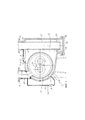
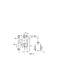
На Фиг. 1 показан механизм закачки многофазной смеси с твердой фазой, который сконструирован как многофазный насос 1. Многофазный насос 1 оборудован кожухом 5, в котором есть входное отверстие 10, входной патрубок 11, разгрузочное отверстие 20, разгрузочный патрубок 21. Набор винтов 30 размещен в корпусе насоса 32. Винты 30 могут быть двухшпиндельными и двухпоточными, в которых направление потока может смещаться наружу от середины винтов 30. Накачиваемая многофазная смесь, содержащая твердую фазу, проходит через впускное отверстие 10 к винтам 30, где установлена всасывающая камера до винтов 30. На проекте конструкции отображена всасывающая камера с винтами 30. Многофазная смесь прокачивается от середины винтов 30 (перпендикулярно рабочей плоскости наружу по обоим сторонам) и оттуда попадает в напорную камеру 40, окружающую винты 30 и насосный корпус 32, в котором находятся винты 30.In FIG. 1 shows the injection mechanism of a multiphase mixture with a solid phase, which is designed as a
У кожуха 5 есть скос, направленный вниз под винтами 30 и сепараторным механизмом со стороны нагнетания 45, которые расширяются в поперечном сечении напорной камеры 40 в направлении выпускного отверстия 20. При увеличении объема и поперечного сечения потока скорость потока внутри напорной камеры 40 уменьшается, что в результате приводит к разделению фаз, существующих в многофазной смеси. Газообразная фаза, у которой наименьший удельный вес, поднимется вверх, жидкая фаза отделится посредине, а твердая фаза, у которой самый большой удельный вес, осядет на дно.The
Газовый выход 61 расположен в верхней части кожуха 5, через который отделившаяся газообразная фаза может выходить отдельно. Труба 60 соединена с газовым выходом 61, на котором расположен клапан 65, предпочтительно регулирующий клапан, который открывается или закрывается в зависимости от требуемой скорости потока. Перемещение газообразной фазы можно осуществить через газовый выход 61 после увеличения напора от винтов 30; как вариант, на трубе 60 можно открыть разгрузочное отверстие 20 и отвести газообразную фазу через разгрузочное отверстие 20 вместе с оставшимися компонентами многофазной смеси. Если клапан 65 перекрыт, газообразная фаза может выводиться через выпускное отверстие 20, которое расположено в зоне под винтами 30. Вместо внешней трубы 60 с клапаном 65 можно предусмотреть сквозное отверстие в верхней части кожуха 5 возле выпускного отверстия 20. Таким образом, прямая обводная линия 60, встроенная в перпендикулярно направленную выпускную трубу 25, обеспечивает обвод к выпускному отверстию 20. Такой подход позволяет простыми средствами разделить и удалить газообразную фазу из напорной камеры 40. Выпускное отверстие 20 выводит многофазную смесь вверх из кожуха на разгрузочную сторону, тогда как открытие выпускного отверстия 20 в напорной камере 40 устанавливается под винтами 30. Нужно отметить, что минимальная площадь поперечного сечения для прохода отделенной газообразной фазы всегда имеется на линии транспортировки. Желаемое удаление жидкой фазы произойдет через выпускное отверстие 20.The
В конструкции корпуса 5 с увеличенным объемом, который используется как сепараторный механизм 45, в нижней части располагается камера отстоя, которая предназначена для улавливания твердых частиц, оседающих на дно при уменьшении потока. Камера отстоя 80 расположена на более низком уровне кожуха 5 и ниже винтов 30, обеспечивающих увеличение напора. Направленная вниз перегородка кожуха 5 ведет от винтов 30 к камере отстоя 80, что позволяет твердым частицам, находящимся на верхнем уровне, спускаться вниз. Разгрузочное отверстие 85 расположено в камере отстоя 80, которое перекрывается крышкой 86. Зона пониженного потока 82 формируется выше камеры отстоя 80, что позволяет отделить жидкую и газообразную фазы в результате разделения путем использования разницы плотностей (гравитационное разделение). Вместо фиксированного перекрытия (крышки) 86 со встроенной инспекционной дверцей можно предусмотреть разгрузочное отверстие 85 с клапаном, центробежным сепаратором и поворотной заслонкой, что позволит вытеснить накопившуюся твердую фазу из камеры отстоя 80 (при необходимости).In the design of the
Выпускное отверстие для жидкости 51 предусматривается над камерой отстоя 80 на разгрузочной стороне 40 в кожухе 5, к которому присоединена линия рециркуляции 50. Линия рециркуляции 50 прокладывается от разгрузочной стороны 40 к всасывающей стороне на входном отверстии 10. Распределительный клапан 55 предусматривается на линии рециркуляции 50, который открывается или перекрывается по мере необходимости, что позволяет регулировать процесс рециркуляции от разгрузочной стороны 40 к всасывающей стороне. Выпускное отверстие для жидкой фазы 51 для рециркуляционной обводной линии 50 располагается над камерой отстоя 80 и ниже винтов 30. В результате расположения выпускного отверстия для жидкой фазы 51 над камерой отстоя 80, жидкая фаза, у которой твердая фаза уже осела, направляется в линию рециркуляции 50. Для оседания и разделения в зоне пониженного потока 82 располагается над осевшей твердой фазой резервуар 90, из которого берется рециркуляционная жидкость.A
На Фиг. 1 как вариант или в дополнение к описанной линии рециркуляции 50 с клапаном 55 отображена линия рециркуляции 50 с зазором или отверстием в корпусе насоса 32. Отверстие или зазор предоставляет возможность соединения камеры всасывания внутри корпуса насоса 32 с напорной камерой 40 вне корпуса насоса 32 и в корпусе 5. Благодаря верхней ориентации отверстия 50, более тяжелые твердые частицы не перемещаются (или практически не перемещаются) к всасывающей стороне. Кроме того, расположение отверстия 50 предусмотрено в верхнем положении с тем, чтобы обеспечить разделение твердой и жидкой фаз, а после этого отделившаяся жидкая фаза могла достичь необходимого уровня воды.In FIG. 1, as an option or in addition to the described
Во время работы по смешению составов многофазной смеси вся напорная камера 40 заполняется многофазной смесью. Если газопровод 60 перекрыт, то вся накачиваемая многофазная смесь отводится через подъемную колонну 25 и разгрузочное отверстие 20 многофазного насоса 1, имеющего сепараторный механизм 45 в корпусе 5. В этом случае подъемная колонна 25 открывается ниже уровня винтов 30 и кожуха насоса 32 и перемещает многофазную смесь из напорной камеры 40 к фланцу 21. Твердая фаза, отделенная и накопленная в камере отстоя 80, перемещается вместе с жидкой фазой. Если скорость потока недостаточна для вывода твердых примесей, расположенных в напорной камере 80, накопленные твердые частицы могут быть выведены из напорной камеры 40 в процессе работы с помощью поворотной заслонки или других средств. Альтернативным вариантом может быть промывка твердых отложений посредством так называемых осадков жидкости.During the work of mixing the compositions of the multiphase mixture, the
В месте расположении выходного отверстия для жидкой фазы 51 над камерой отстоя 80 в направлении силы тяжести жидкая фаза, очищенная от твердой фазы, рециркулирует для уплотнения зазора между винтами 30 и кожухом насоса 32 и для обеспечения смазки. Абразивные твердые частицы в значительной степени удерживаются, поскольку они находятся ниже резервуара 90 в камере отстоя 80. На чертеже не показано конструктивного разделения резервуара 90 и камеры отстоя 80; замедлители потока могут находится в корпусе 5 внутри напорной камеры 40, которые сохраняют твердые частицы или препятствуют их перемещению к выходному отверстию для жидкой фазы 51. Указанные замедлители потока могут, например, иметь форму лабиринтообразных направляющих или перемычек.At the location of the outlet for the
Дополнительное выходное отверстие 70 располагается на нижней части кожуха 5, используется для слива в целях проведения техобслуживания и ремонтных работ, но процессе работы перекрывается.An
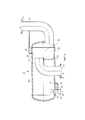
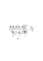
Модифицированный вариант изобретения изображен на Фиг. 2, в котором сепараторный механизм 45 устанавливается отдельно. Сепараторный механизм 45 можно подключить к многофазному насосу 1 (см. Фиг. 3).A modified embodiment of the invention is shown in FIG. 2, in which the
На Фиг. 3 представлен стандартный многофазный насос 1 в форме винтового насоса. В данном случае винты 30 расположены внутри кожуха насоса 32, который установлен внутри напорной камеры 40 кожуха 5. Прокачиваемая среда проходит через входное отверстие 10 на входной патрубок 11 к винтам 30, а оттуда перпендикулярно наружу в напорную камеру 40, расположенную вокруг корпуса насоса 32 с насосными винтами 30. Накачанная многофазная смесь отводится из напорной камеры 40, находясь в кольцевом пространстве, к выходному отверстию насоса 20'.In FIG. 3 shows a standard
На Фиг. 2 показан сепараторный механизм 45 как отдельный компонент с соответствующими соединительными патрубками. Входные патрубки 11 для входного отверстия 10 предусмотрены для соединения входных патрубков 11 многофазного насоса 1 (см. Фиг. 3); входной патрубок 11 соединен с трубчатым кожухом 100. Выходное отверстие насоса 20 соединяется с корпусом 100 через выпускные патрубки 21 многофазного насоса 1 (см. Фиг. 3). Многофазная смесь протекает от входного отверстия 10, через многофазный насос 1, к выходному отверстию 20 многофазного насоса 1 (по стрелкам), в сепараторную камеру 45, и оттуда через выходное отверстие 20 к транспортировочным трубам или для дальнейших процессов обработки. Входное отверстие сепараторной камеры 45 устанавливается в виде согнутой под углом 90° трубы, что позволяет перемещаться многофазной смеси строго горизонтально к сепараторной камере 45.In FIG. 2 shows a
Камера отстоя 80 с зоной пониженного потока 82 предусмотрена внутри сепараторной камеры 45, в которой многофазная смесь выкачивается из многофазного насоса 1. Выходное отверстие 85 с крышкой 86 предусматривается в нижней части камеры отстоя 80. Подъемная колонна 25 устанавливается перпендикулярно вверх от камеры отстоя 80.A
Камера отстоя 80 соединена с резервуаром 90 через разделительную перегородку 95, в которой находится канал. Жидкая фаза, полностью очищенная от твердой фазы, накапливается в резервуаре 90, затем повторно рециркулируется к входному отверстию 10 через линию рециркуляции 50. Также в одном из вариантов здесь устанавливается регулировочный клапан 55 на линии рециркуляции 50; альтернативным или дополнительным вариантом может быть установка обводной линии 50 на всасывающем патрубке входного отверстия 10. Чтобы улучшить качество жидкой фазы, можно установить ряд разделительных перегородок 95 по потоку вверх на линии рециркуляции 50, каждая из которых учитывает транспортировку жидкой фазы через каналы 96 или переливы в направлении обвода 50. Для этих целей необходимо создать серию камер отстоя 80 и зон пониженного потока 82 внутри корпуса 100. Таким образом, предусматривается возможность многоступенчатого разделения жидкой и твердой фаз.The
Выпускное отверстие для газа (газоотвод) 61 с газопроводом 60 и клапаном 65 предусматривается в верхней части корпуса 100, что позволит отделившейся газовой фазе внутри корпуса 100 переместиться или в направлении выпускного отверстия 20, или к отдельному газопроводу. Аналогично жидкой фазе с линии рециркуляции 50, предусматривается также отверстие (канал) 60 - линия от сепараторной камеры внутри кожуха 100 к выходному отверстию 20.A gas outlet (gas outlet) 61 with a
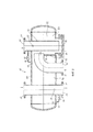
Модификация изобретения изображена на Фиг. 4. Принцип работы отдельной сепараторной камеры 45 отображен на Фиг. 2, хотя впускное отверстие 10 для многофазного насоса не проходит от источника через перегородку корпуса. Подключение к многофазному насосу 1 (Фиг. 3) выполняется через выпускные патрубки 21, тогда как входное отверстие 10 многофазного насоса 1 соединяется с нагнетательной трубой и т.п. В сепараторном механизме (Фиг. 4) отделившаяся жидкая фаза соединяется по линии рециркуляции 50 со всасывающей стороной через входное отверстие 10, которое не соединено с линией подачи. Поэтому отделившаяся жидкая фаза подается на всасывающую сторону во впускное отверстие 10 винтового насоса.A modification of the invention is shown in FIG. 4. The principle of operation of the
На всасывающей стороне многофазного насоса 1 могут устанавливаться устройства для сбора жидкой фазы, например, трубопроводы с U-образным профилем, емкости или резервуары, посредством которых контролируемое количество жидкой фазы подается на входную сторону. Это предусматривает возможность того, что, с одной стороны, большое количество тепла выведется из корпуса 5 многофазного насоса 1 и, с другой стороны, накопленная твердая фаза выведется из сепараторных механизмов 45.On the suction side of the
На Фиг. 4 выпускное отверстие 20 из камеры отстоя 80 располагается горизонтально, что позволит легко вывести осевшую твердую фазу из камеры отстоя 80. Определенный противоток многофазной смеси обуславливается изгибающимся вверх выходным отверстием 20, что приводит к разделению и осадку твердой фазы внутри камеры отстоя.In FIG. 4, the
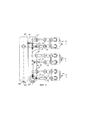
На Фиг. 5 показано (вид сбоку) расположение некоторого количества многофазных насосов 1, подключенных параллельно, которые оборудованы отдельной сепараторной камерой 45 и восходящими средствами сбора 110, в которые закачанная многофазная смесь поставляется и первоначально накапливается из подающей трубы (на Фиг. не показано) при помощи впускного патрубка 111. От сборного контейнера 110 для каждого многофазного насоса 1, входной трубопровод ведет к входному отверстию 10 каждого соответствующего многофазного насоса 1. Входной трубопровод имеет U-образный профиль и предполагается для контроля образования остатков жидкости. Жидкость собирается небольшими дозами при помощи U-образной структуры входного трубопровода, в котором достаточно большой диаметр трубы предотвращает любое пневматическое перемещение оставшейся массы. Внутри U-образной секции входного трубопровода жидкая фаза с твердыми частицами и газообразная фаза отделяются друг от друга в горизонтальной секции трубопровода. Жидкая фаза с твердыми частицами сохраняется и накапливается, в то время как газообразная фаза протекает над ней через трубопровод. При увеличении жидкого объема внутри горизонтальных секций трубопровода диаметр потока газообразной фазы уменьшается. Поэтому, исходя из разности скоростей газообразной фазы и жидкой фазы с твердыми частицами, на границе фаз образуются волны, которые полностью блокируют пути проникновения потока газообразной фазы. Если происходит такое явление, газообразные фазы проталкивают остатки жидкости перед собой над поднимающейся секцией, которая соединена с горизонтальной секцией трубопровода, вверх и во входное отверстие 10 многофазного насоса 1. Периодичность остатков жидкости и их объем определяется взаимосвязью между отдельными параметрами закачки (количество закачанного и газообразного компонента) и геометрическими параметрами трубопровода (диаметр, длина горизонтальной части и разность высот возрастающей секции).In FIG. 5 shows (side view) the location of a number of
В дополнение к сборному контейнеру 110, корпус 100 отдельного сепараторного механизма 45 (Фиг. 5) соединен с многофазным насосом 1 через выходные отверстия насоса 20'. Общее выходное отверстие 20 ведет от сепараторного механизма 45 до транспортных линий. Линия рециркуляции 50 с клапаном 55 расположена на обратной стороне кожуха 100 и ведет к впускному отверстию 10 насоса 1. Периодичность и объем остатков жидкости можно регулировать через контролируемую подачу отделившейся жидкой фазы согласно расположению и соединению линии рециркуляции 50 с возрастающей секцией линии подачи. Дополнительная линия рециркуляции 50, для которой можно предусмотреть клапан, ведет от сепараторного механизма 45 к сборному контейнеру 110, что допускает управление секцией входного трубопровода или стороны всасывания, на которой отделившаяся жидкая фаза рециркулирует.In addition to the
На Фиг. 6 показано параллельное расположение трех многофазных насосов 1 - вид сверху (Фиг. 5). Перекачиваемая многофазная смесь, которая подается из источника, направляется через впускной патрубок 111 в сборный контейнер 110. От указанного сборного контейнера 110 три подводящие U-образные трубы ведут под сепараторный механизм 45 через впускные отверстия 10 многофазных насосов 1. После закачивания многофазная смесь перемещается в сепараторный механизм 45 через выпускные отверстия насоса 20', сепарируется там и выводится через выходное отверстие 20. На обратной стороне кожуха 100 располагается общее выпускное отверстие для жидкой фазы 51, которое соединено с трубопроводом, от которого линии рециркуляции 50 ведут к впускным отверстиям 10 и сборным контейнерам 110 на всасывающих сторонах насосов 1. Распределительный клапан 55 устанавливается на каждую линию рециркуляции 50, чтобы обеспечить в каждом насосе 1 контролируемую подачу отделившейся жидкой фазы. Таким образом, представляется возможность, например, при запуске насоса предусмотреть полное открытие линии рециркуляции 50 и, как следствие, уменьшить противодавления, что может существенно разгрузить и сделать запуск насоса 1 энергоэффективным.In FIG. 6 shows a parallel arrangement of three multiphase pumps 1 - a top view (Fig. 5). The multiphase pumped mixture, which is supplied from the source, is sent through the
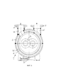
На Фиг. 7 показан вид в поперечном разрезе по линии Α-A (Фиг. 5). Отдельный сепараторный механизм 45 показан в поперечном разрезе рядом с подводящей трубой на стороне всасывания. Выходные отверстия насоса 20' направлены в кожух 100 в общую трубу, которая вставляется в камеру отстоя 80 внутри корпуса 100. Разделительная стенка 95 показана также как крышка 86, конструкция согласуется с конструкцией на Фиг. 4, обводной трубопровод 60 с клапаном 65 для газообразной фазы, выходящей из верхней части кожуха 100 непосредственно к разгрузочному отверстию 20.In FIG. 7 is a cross-sectional view taken along line Α-A (FIG. 5). A
На Фиг. 7 справа отображена линия В-В (вид в поперечном разрезе). Как видно, сборная труба разгрузочных отверстий 20' открывается перпендикулярно в камере отстоя 80. Оттуда разгрузочное отверстие 20 идет перпендикулярно вверх и затем горизонтально изгибается, что позволяет отвести многофазную смесь. После разделения жидкой фазы от твердой фазы в сепараторной камере, отделенная жидкая фаза проводится через заградительную стенку 95 в кожух 100 сепараторного механизма 45. Жидкая фаза, отделенная от твердой фазы, вытекает из выходного отверстия для жидкой фазы через линию рециркуляции 50 с отдельными клапанами 55 в подводящей трубе 10 на стороне всасывания многофазных насосов 1. Крышка 86 находится на нижней стороне камеры отстоя 80.In FIG. 7, the line BB is shown on the right (cross-sectional view). As can be seen, the collection pipe of the discharge openings 20 'opens perpendicularly to the
Claims (27)
Applications Claiming Priority (3)
| Application Number | Priority Date | Filing Date | Title |
|---|---|---|---|
| DE102012015064.4A DE102012015064B4 (en) | 2012-07-31 | 2012-07-31 | Method for operating a multi-phase pump and device thereto |
| DE102012015064.4 | 2012-07-31 | ||
| PCT/EP2013/002260 WO2014019687A2 (en) | 2012-07-31 | 2013-07-31 | Method for operating a multi-phase pump and apparatus therefor |
Publications (2)
| Publication Number | Publication Date |
|---|---|
| RU2014152045A RU2014152045A (en) | 2016-09-20 |
| RU2638897C2 true RU2638897C2 (en) | 2017-12-18 |
Family
ID=48979701
Family Applications (1)
| Application Number | Title | Priority Date | Filing Date |
|---|---|---|---|
| RU2014152045A RU2638897C2 (en) | 2012-07-31 | 2013-07-31 | Method of multiphase pump operation and its arrangement |
Country Status (12)
| Country | Link |
|---|---|
| US (2) | US9689385B2 (en) |
| EP (1) | EP2880313B1 (en) |
| JP (1) | JP6324957B2 (en) |
| KR (1) | KR102036224B1 (en) |
| CN (1) | CN104487715B (en) |
| BR (1) | BR112015000844A2 (en) |
| CA (1) | CA2877513C (en) |
| DE (1) | DE102012015064B4 (en) |
| IN (1) | IN2014KN02982A (en) |
| MX (1) | MX362235B (en) |
| RU (1) | RU2638897C2 (en) |
| WO (1) | WO2014019687A2 (en) |
Families Citing this family (6)
| Publication number | Priority date | Publication date | Assignee | Title |
|---|---|---|---|---|
| EP3371454A4 (en) * | 2015-11-02 | 2019-05-08 | Flowserve Management Company | Multi-phase pump with cooled liquid reservoir |
| JP2019512075A (en) * | 2016-02-16 | 2019-05-09 | サビック グローバル テクノロジーズ ベスローテン フェンノートシャップ | Method and system for cooling treatment plant water |
| GB2578012B (en) | 2017-05-15 | 2022-06-15 | Aker Solutions As | System and method for fluid processing |
| SE541077C2 (en) * | 2017-09-05 | 2019-03-26 | Husqvarna Ab | Separator, separator system and methods of their operation |
| US10926197B2 (en) | 2018-06-22 | 2021-02-23 | Hamilton Sunstrand Corporation | Multifunctional phase separation apparatus |
| DE102020133760A1 (en) | 2020-12-16 | 2022-06-23 | Leistritz Pumpen Gmbh | Process for conveying a fluid through a screw pump and screw pump |
Citations (5)
| Publication number | Priority date | Publication date | Assignee | Title |
|---|---|---|---|---|
| GB2405906A (en) * | 2003-09-12 | 2005-03-16 | Aesseal Plc | Liquid ring vacuum pump with automatically maintained level of barrier fluid |
| RU2366833C1 (en) * | 2008-04-17 | 2009-09-10 | Открытое акционерное общество "Татарский научно-исследовательский и проектно-конструкторский институт нефтяного машиностроения" (ОАО "ТатНИИнефтемаш") | Multi-phase screw pump |
| US20110103987A1 (en) * | 2009-11-04 | 2011-05-05 | General Electric Company | Pump system |
| DE102010019238A1 (en) * | 2010-05-03 | 2011-11-24 | Joh. Heinr. Bornemann Gmbh | Container, sump and multi-phase pump system and method for separating and splitting a multi-phase mixture |
| US20120048113A1 (en) * | 2010-08-31 | 2012-03-01 | General Electric Company | System and method for multiphase pump lubrication |
Family Cites Families (26)
| Publication number | Priority date | Publication date | Assignee | Title |
|---|---|---|---|---|
| US2381695A (en) * | 1943-03-11 | 1945-08-07 | Laval Steam Turbine Co | Pumping system |
| NL6501909A (en) * | 1964-06-25 | 1965-12-27 | ||
| DE1607694C3 (en) * | 1967-02-11 | 1974-08-29 | Deutsche Gold- Und Silber-Scheideanstalt Vormals Roessler, 6000 Frankfurt | Plant for the separation of solids from aerosols |
| US3559809A (en) * | 1969-02-07 | 1971-02-02 | Amf Inc | Filter back wash means |
| DE4316735C2 (en) | 1993-05-19 | 1996-01-18 | Bornemann J H Gmbh & Co | Pumping method for operating a multi-phase screw pump and pump |
| JP3712817B2 (en) * | 1997-03-27 | 2005-11-02 | 株式会社日立製作所 | Hybrid gear pump and hydraulic circuit of engine using the same |
| US6033577A (en) * | 1998-05-18 | 2000-03-07 | Dravo Lime Company | Coordination of liquid-solid separators and fluid tanks |
| US6214092B1 (en) * | 1998-11-12 | 2001-04-10 | Larry G. Odom | Fracturing material separator apparatus |
| US6358411B1 (en) * | 2000-05-19 | 2002-03-19 | Mckinney Jerry L. | Wastewater treatment plant |
| US6662951B1 (en) * | 2000-09-27 | 2003-12-16 | Basic Resources, Inc. | Process for extracting and purifying naturally occurring zeolite |
| FR2818702B1 (en) * | 2000-12-21 | 2003-04-11 | Roxer | DEVICE AND METHOD FOR INJECTING A GASEOUS FUEL IN LIQUID FORM FOR INTERNAL COMBUSTION ENGINES |
| DE10350226B4 (en) | 2003-10-27 | 2005-11-24 | Joh. Heinr. Bornemann Gmbh | Method for conveying multiphase mixtures and pump system |
| US7255233B2 (en) * | 2004-06-14 | 2007-08-14 | Uchicago Argonne Llc | Method and apparatus for separating mixed plastics using flotation techniques |
| US7569097B2 (en) | 2006-05-26 | 2009-08-04 | Curtiss-Wright Electro-Mechanical Corporation | Subsea multiphase pumping systems |
| US7708059B2 (en) | 2007-11-13 | 2010-05-04 | Baker Hughes Incorporated | Subsea well having a submersible pump assembly with a gas separator located at the pump discharge |
| DE102008018407B4 (en) | 2008-04-10 | 2012-03-22 | Joh. Heinr. Bornemann Gmbh | Underwater delivery unit |
| JP5104656B2 (en) * | 2008-08-26 | 2012-12-19 | 株式会社豊田自動織機 | Variable displacement rotary pump |
| US20100278672A1 (en) * | 2009-04-30 | 2010-11-04 | General Electric Company | Method and apparatus for lubricating a screw pump system |
| US20100278671A1 (en) * | 2009-04-30 | 2010-11-04 | General Electric Company | Method and apparatus for reducing particles in a screw pump lubricant |
| US8419398B2 (en) * | 2009-04-30 | 2013-04-16 | General Electric Company | Method and apparatus for managing fluid flow within a screw pump system |
| US20120211230A1 (en) * | 2009-10-27 | 2012-08-23 | Karl Gregory Anderson | Subsea separation systems |
| US9101859B2 (en) * | 2012-06-01 | 2015-08-11 | Dow Global Technologies Llc | Cross-flow filtration system including particulate settling zone |
| US8986431B2 (en) * | 2012-11-14 | 2015-03-24 | Pall Corporation | Purification arrangements and methods for gas pipeline systems |
| JP6143633B2 (en) * | 2013-10-15 | 2017-06-07 | 住友重機械工業株式会社 | Compressor and compressor oil quantity management system |
| US10036319B2 (en) * | 2014-10-31 | 2018-07-31 | General Electric Company | Separator assembly for a gas turbine engine |
| US10233925B2 (en) * | 2016-06-23 | 2019-03-19 | James D. Sutton | Scalable hydraulic motor with drive input shaft and driven output shaft |
-
2012
- 2012-07-31 DE DE102012015064.4A patent/DE102012015064B4/en active Active
-
2013
- 2013-07-31 JP JP2015524668A patent/JP6324957B2/en active Active
- 2013-07-31 BR BR112015000844A patent/BR112015000844A2/en not_active IP Right Cessation
- 2013-07-31 KR KR1020157003094A patent/KR102036224B1/en active IP Right Grant
- 2013-07-31 EP EP13747969.7A patent/EP2880313B1/en active Active
- 2013-07-31 WO PCT/EP2013/002260 patent/WO2014019687A2/en active Application Filing
- 2013-07-31 US US14/405,314 patent/US9689385B2/en active Active
- 2013-07-31 RU RU2014152045A patent/RU2638897C2/en not_active IP Right Cessation
- 2013-07-31 CN CN201380038882.4A patent/CN104487715B/en active Active
- 2013-07-31 MX MX2014015877A patent/MX362235B/en active IP Right Grant
- 2013-07-31 CA CA2877513A patent/CA2877513C/en active Active
- 2013-07-31 IN IN2982KON2014 patent/IN2014KN02982A/en unknown
-
2017
- 2017-05-23 US US15/602,472 patent/US11143180B2/en active Active
Patent Citations (5)
| Publication number | Priority date | Publication date | Assignee | Title |
|---|---|---|---|---|
| GB2405906A (en) * | 2003-09-12 | 2005-03-16 | Aesseal Plc | Liquid ring vacuum pump with automatically maintained level of barrier fluid |
| RU2366833C1 (en) * | 2008-04-17 | 2009-09-10 | Открытое акционерное общество "Татарский научно-исследовательский и проектно-конструкторский институт нефтяного машиностроения" (ОАО "ТатНИИнефтемаш") | Multi-phase screw pump |
| US20110103987A1 (en) * | 2009-11-04 | 2011-05-05 | General Electric Company | Pump system |
| DE102010019238A1 (en) * | 2010-05-03 | 2011-11-24 | Joh. Heinr. Bornemann Gmbh | Container, sump and multi-phase pump system and method for separating and splitting a multi-phase mixture |
| US20120048113A1 (en) * | 2010-08-31 | 2012-03-01 | General Electric Company | System and method for multiphase pump lubrication |
Also Published As
| Publication number | Publication date |
|---|---|
| DE102012015064B4 (en) | 2018-08-02 |
| CN104487715A (en) | 2015-04-01 |
| JP6324957B2 (en) | 2018-05-16 |
| CA2877513A1 (en) | 2014-02-06 |
| JP2015523498A (en) | 2015-08-13 |
| WO2014019687A3 (en) | 2014-06-26 |
| BR112015000844A2 (en) | 2017-06-27 |
| EP2880313A2 (en) | 2015-06-10 |
| MX2014015877A (en) | 2015-08-05 |
| MX362235B (en) | 2019-01-09 |
| US20170254328A1 (en) | 2017-09-07 |
| KR20150038001A (en) | 2015-04-08 |
| EP2880313B1 (en) | 2021-06-30 |
| WO2014019687A8 (en) | 2015-01-15 |
| WO2014019687A2 (en) | 2014-02-06 |
| KR102036224B1 (en) | 2019-11-26 |
| CN104487715B (en) | 2018-04-17 |
| RU2014152045A (en) | 2016-09-20 |
| DE102012015064A1 (en) | 2014-02-06 |
| CA2877513C (en) | 2019-07-09 |
| IN2014KN02982A (en) | 2015-05-08 |
| US9689385B2 (en) | 2017-06-27 |
| US11143180B2 (en) | 2021-10-12 |
| US20150226214A1 (en) | 2015-08-13 |
Similar Documents
| Publication | Publication Date | Title |
|---|---|---|
| RU2638897C2 (en) | Method of multiphase pump operation and its arrangement | |
| EP3137732B1 (en) | Multiphase separation system | |
| EP3116621B1 (en) | Split flow pipe separator with sand traps comprising a sand cyclone and process using it | |
| RU2716120C2 (en) | Separator for fluid medium obtained from oil well and separation device containing it | |
| US7854849B2 (en) | Compact multiphase inline bulk water separation method and system for hydrocarbon production | |
| SK286611B6 (en) | Combined degassing and flotation tank and use thereof | |
| MXPA06008261A (en) | Separation of crude oil at the well head. | |
| US20180073343A1 (en) | Method and System for Subsea Purification of Produced Water From Subsea Oil Producing Installations | |
| RU2754106C1 (en) | Method for catching and disposing of sand from products of petroleum and gas boreholes and apparatus for implementation thereof | |
| RU2308313C1 (en) | Liquid-gas separator | |
| CN111573871A (en) | Closed oily sewage treatment device and process | |
| US20180154282A1 (en) | Method and device for separation of liquids and gas with use of inclined and rounded holes or channels in the wall of a pipe | |
| CN212334813U (en) | Closed oily sewage treatment plant | |
| RU2361641C1 (en) | Tube separation installation | |
| RU2473373C1 (en) | Discharge phase separator | |
| RU2683463C1 (en) | Method of lifting inhomogeneous multi-phase products from wells and device for its implementation | |
| RU2636313C1 (en) | Oil purification plant | |
| RU2469766C1 (en) | Settling tank for purification of oil-containing wastewater | |
| CN109896570A (en) | A kind of enclosed air-floating apparatus | |
| CN105771491A (en) | Efficient tail gas automatic purifying device | |
| NO20160209A1 (en) | Method and system for subsea purification of produced water from subsea oil producing installations. |
Legal Events
| Date | Code | Title | Description |
|---|---|---|---|
| MM4A | The patent is invalid due to non-payment of fees |
Effective date: 20200801 |