US6033577A - Coordination of liquid-solid separators and fluid tanks - Google Patents
Coordination of liquid-solid separators and fluid tanks Download PDFInfo
- Publication number
- US6033577A US6033577A US09/080,655 US8065598A US6033577A US 6033577 A US6033577 A US 6033577A US 8065598 A US8065598 A US 8065598A US 6033577 A US6033577 A US 6033577A
- Authority
- US
- United States
- Prior art keywords
- fluid
- liquid
- tank
- bank
- line
- Prior art date
- Legal status (The legal status is an assumption and is not a legal conclusion. Google has not performed a legal analysis and makes no representation as to the accuracy of the status listed.)
- Expired - Fee Related
Links
- 239000012530 fluid Substances 0.000 title claims abstract description 147
- 239000007787 solid Substances 0.000 title claims abstract description 128
- 238000000034 method Methods 0.000 claims abstract description 37
- 230000008859 change Effects 0.000 claims description 7
- 230000004044 response Effects 0.000 claims description 6
- 230000008569 process Effects 0.000 abstract description 9
- 238000004886 process control Methods 0.000 abstract description 5
- 238000000926 separation method Methods 0.000 abstract description 4
- 239000007800 oxidant agent Substances 0.000 description 30
- 230000008929 regeneration Effects 0.000 description 20
- 238000011069 regeneration method Methods 0.000 description 20
- 238000005201 scrubbing Methods 0.000 description 17
- 238000010790 dilution Methods 0.000 description 16
- 239000012895 dilution Substances 0.000 description 16
- 239000000347 magnesium hydroxide Substances 0.000 description 15
- 229910001862 magnesium hydroxide Inorganic materials 0.000 description 15
- 239000002609 medium Substances 0.000 description 15
- OSGAYBCDTDRGGQ-UHFFFAOYSA-L calcium sulfate Chemical compound [Ca+2].[O-]S([O-])(=O)=O OSGAYBCDTDRGGQ-UHFFFAOYSA-L 0.000 description 14
- VTHJTEIRLNZDEV-UHFFFAOYSA-L magnesium dihydroxide Chemical compound [OH-].[OH-].[Mg+2] VTHJTEIRLNZDEV-UHFFFAOYSA-L 0.000 description 14
- 239000007788 liquid Substances 0.000 description 11
- 238000006477 desulfuration reaction Methods 0.000 description 9
- 230000023556 desulfurization Effects 0.000 description 9
- 150000003467 sulfuric acid derivatives Chemical class 0.000 description 9
- 238000010586 diagram Methods 0.000 description 8
- 239000007864 aqueous solution Substances 0.000 description 6
- 239000000243 solution Substances 0.000 description 6
- 235000008733 Citrus aurantifolia Nutrition 0.000 description 5
- FYYHWMGAXLPEAU-UHFFFAOYSA-N Magnesium Chemical compound [Mg] FYYHWMGAXLPEAU-UHFFFAOYSA-N 0.000 description 5
- 235000011941 Tilia x europaea Nutrition 0.000 description 5
- 239000004571 lime Substances 0.000 description 5
- 239000011777 magnesium Substances 0.000 description 5
- 229910052749 magnesium Inorganic materials 0.000 description 5
- LSNNMFCWUKXFEE-UHFFFAOYSA-L sulfite Chemical class [O-]S([O-])=O LSNNMFCWUKXFEE-UHFFFAOYSA-L 0.000 description 5
- UGFAIRIUMAVXCW-UHFFFAOYSA-N Carbon monoxide Chemical compound [O+]#[C-] UGFAIRIUMAVXCW-UHFFFAOYSA-N 0.000 description 4
- RAHZWNYVWXNFOC-UHFFFAOYSA-N Sulphur dioxide Chemical compound O=S=O RAHZWNYVWXNFOC-UHFFFAOYSA-N 0.000 description 4
- 239000003546 flue gas Substances 0.000 description 4
- 239000007789 gas Substances 0.000 description 4
- 239000000203 mixture Substances 0.000 description 4
- 239000000523 sample Substances 0.000 description 4
- 241000446313 Lamella Species 0.000 description 3
- 239000012736 aqueous medium Substances 0.000 description 3
- 230000008901 benefit Effects 0.000 description 3
- 229910052602 gypsum Inorganic materials 0.000 description 3
- 239000010440 gypsum Substances 0.000 description 3
- 239000002002 slurry Substances 0.000 description 3
- 239000000126 substance Substances 0.000 description 3
- CSNNHWWHGAXBCP-UHFFFAOYSA-L Magnesium sulfate Chemical compound [Mg+2].[O-][S+2]([O-])([O-])[O-] CSNNHWWHGAXBCP-UHFFFAOYSA-L 0.000 description 2
- AXCZMVOFGPJBDE-UHFFFAOYSA-L calcium dihydroxide Chemical compound [OH-].[OH-].[Ca+2] AXCZMVOFGPJBDE-UHFFFAOYSA-L 0.000 description 2
- 239000000920 calcium hydroxide Substances 0.000 description 2
- 229910001861 calcium hydroxide Inorganic materials 0.000 description 2
- 230000007423 decrease Effects 0.000 description 2
- 230000003247 decreasing effect Effects 0.000 description 2
- 230000001419 dependent effect Effects 0.000 description 2
- 230000004048 modification Effects 0.000 description 2
- 238000012986 modification Methods 0.000 description 2
- 239000002245 particle Substances 0.000 description 2
- 238000001556 precipitation Methods 0.000 description 2
- 239000002562 thickening agent Substances 0.000 description 2
- OYPRJOBELJOOCE-UHFFFAOYSA-N Calcium Chemical compound [Ca] OYPRJOBELJOOCE-UHFFFAOYSA-N 0.000 description 1
- LSNNMFCWUKXFEE-UHFFFAOYSA-N Sulfurous acid Chemical class OS(O)=O LSNNMFCWUKXFEE-UHFFFAOYSA-N 0.000 description 1
- 239000006096 absorbing agent Substances 0.000 description 1
- 238000010521 absorption reaction Methods 0.000 description 1
- 239000007900 aqueous suspension Substances 0.000 description 1
- QVGXLLKOCUKJST-UHFFFAOYSA-N atomic oxygen Chemical compound [O] QVGXLLKOCUKJST-UHFFFAOYSA-N 0.000 description 1
- 230000015572 biosynthetic process Effects 0.000 description 1
- 239000011575 calcium Substances 0.000 description 1
- 229910052791 calcium Inorganic materials 0.000 description 1
- 238000003889 chemical engineering Methods 0.000 description 1
- 238000000605 extraction Methods 0.000 description 1
- -1 magnesium hydroxide ions Chemical class 0.000 description 1
- 229910052943 magnesium sulfate Inorganic materials 0.000 description 1
- 235000019341 magnesium sulphate Nutrition 0.000 description 1
- 230000003647 oxidation Effects 0.000 description 1
- 238000007254 oxidation reaction Methods 0.000 description 1
- 230000001590 oxidative effect Effects 0.000 description 1
- 229910052760 oxygen Inorganic materials 0.000 description 1
- 239000001301 oxygen Substances 0.000 description 1
- 238000012856 packing Methods 0.000 description 1
- 238000005498 polishing Methods 0.000 description 1
- 230000000630 rising effect Effects 0.000 description 1
- 239000011885 synergistic combination Substances 0.000 description 1
- 238000004448 titration Methods 0.000 description 1
- 238000011144 upstream manufacturing Methods 0.000 description 1
- XLYOFNOQVPJJNP-UHFFFAOYSA-N water Substances O XLYOFNOQVPJJNP-UHFFFAOYSA-N 0.000 description 1
- 238000005200 wet scrubbing Methods 0.000 description 1
Images

Classifications
-
- B—PERFORMING OPERATIONS; TRANSPORTING
- B01—PHYSICAL OR CHEMICAL PROCESSES OR APPARATUS IN GENERAL
- B01D—SEPARATION
- B01D21/00—Separation of suspended solid particles from liquids by sedimentation
- B01D21/30—Control equipment
- B01D21/34—Controlling the feed distribution; Controlling the liquid level ; Control of process parameters
Definitions
- the present invention applies to liquid tanks connected to liquid-solid separators such as centrifugal separators. While not limited to industrial and chemical engineering uses, the present invention is typically applied in these areas.
- the present invention is designed to overcome problems associated generally with operating liquid-solid separators connected to liquid tanks and more specifically with operating separators and tanks as components of a larger system.
- one application of the present invention is the method and apparatus of process control of liquid-solid separators connected to fluid tanks as part of the system for treating spent scrubbing medium from flue gas desulfurization wet scrubbers.
- sulfur dioxide-containing flue gas may be scrubbed with a slurry containing magnesium scrubbing components.
- the scrubbing takes place, for example, in an absorption tower in which the gas flow is typically countercurrent to and in intimate contact with a scrubbing solution.
- the solution may flow over packing or trays, or be sprayed into an open section of the tower.
- Spent scrubbing fluid in a desulfurization wet scrubber is largely comprised of sulfites.
- This scrubbing fluid needs to be treated to convert sulfites into readily usable or disposable products such as magnesium hydroxide and calcium sulfate.
- the treatment process is started by removing a portion of the scrubbing fluid to an oxidizer.
- the aqueous scrubbing fluid comprised mainly of sulfites, is contacted at least with an oxygen-containing gas, such as air, which is typically sparged through the unit and removed from the top after contact with the fluid.
- the sulfites are converted to sulfates.
- This treated aqueous scrubbing fluid contains dissolved sulfates and suspended sulfates as well as other minor suspended solids.
- the fluid is then discharged to a first group, or bank, of liquid-solid separators.
- the liquid-solid separator uses centrifugal force to separate the smaller low density particles from the larger high density particles.
- the oxidized medium is separated into an overflow of sulfates containing few suspended solids and an underflow with a heavier concentration of suspended solids.
- the overflow is clarified and passed to a regeneration tank.
- the underflow of calcium sulfate may be further contacted with additional solution in the dilution tank before the resulting aqueous solution is discharged to a third bank of liquid-solid separators wherein the solution is once again separated into an overflow and an underflow.
- the captured magnesium hydroxide in the overflow can be recycled back to the absorber tower and calcium sulfate in the underflow solution can be recycled back to the oxidizer.
- the present invention comprises an on-line control method and apparatus for the controlling and coordination of the liquid tanks and liquid-solid separators.
- the coordination is necessary to help optimize the use of liquid-solid separators, optimize feed tank levels to avoid tank overflow, to maintain a continuous fluid flow and to help eliminate fluid line back pressure.
- One or more oxidizing tanks, regeneration tanks, and further dilution tanks may each be connected to a bank of liquid-solid separators.
- the method and apparatus of the present invention are applicable to fluid tanks connected to liquid-solid separators, but the present invention will be illustrated in the context of a system for the desulfurization of sulfur dioxide containing gas from a wet scrubbing unit.
- a change in the number of separators in operation changes the pressure of the fluid in the line between the fluid feed tank and liquid-solid separators.
- the control method of the present invention obtains data from a sensor about the change in fluid pressure, computes a value based on this data, and generates a second command signal to respond to increased or decreased pressure in the fluid feed line.
- the command signal is directed to increasing or decreasing the speed of the pump or opening or closing a control valve.
- the pump speed or control valve position will change in order to better maintain a constant line fluid pressure.
- the apparatus for carrying out the method of the present invention comprises fluid sensors on a fluid feed tank, an exit line containing an in-line pump that extends from the fluid feed tank to a bank of separators or optionally an in-line control valve on a recirculation line connected to a control apparatus, fluid pressure sensors on the bank of separators, a liquid-solid separator controller such as an automated valve and a coordination controller.
- FIG. 3 is a block diagram and functional schematic representation of the details of the bank of hydroclones of FIG. 1;
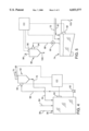
- FIG. 4 is a block diagram and functional schematic representation of the details of the regeneration tank of FIG. 1 connected to a bank of liquid-solid separators;
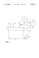
- FIG. 7 is a block diagram and functional schematic representation of the details of the dilution tank of FIG. 5 having a recirculation line with an in-line control valve connected to a control apparatus.
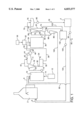
- FIG. 1 a flow diagram for the treatment of spent scrubbing medium from a desulfurization wet scrubber.
- the method and apparatus for the simultaneous control of the number of automated liquid-solid separators in service and the pump speed are integrated into this embodiment and detailed in the accompanying illustrations.
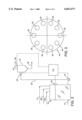
- FIG. 2 shows oxidizer tank 10 connected to liquid-solid separators bank 18 of FIG. 1 by feed line 22.
- liquid-solid separator 18 is a bank of individual hydroclones 20.
- FIG. 3 shows oxidizer tank 10 connected to liquid-solid separators bank 18 of FIG. 1 by feed line 22.
- liquid-solid separator 18 is a bank of individual hydroclones 20.
- FIG. 3 shows oxidizer tank 10 connected to liquid-solid separators bank 18 of FIG. 1 by feed line 22.
- liquid-solid separator 18 is a bank of individual hydroclones 20.
- FIG. 3 shows oxidizer tank 10 connected to liquid-solid separators bank 18 of FIG. 1 by feed line 22.
- liquid-solid separator 18 is a bank of individual hydroclones 20.
- FIG. 3 shows oxidizer tank 10 connected to liquid-solid separators bank 18 of FIG. 1 by feed line 22.
- liquid-solid separator 18 is a bank of individual hydroclones 20.
- FIG. 3 shows oxidizer tank 10
- Coordination controller CC may be for example, a pneumatic, electric, digital, programmable logic controller, or other controller system known in the art which is programmable and preset so that it operates in response to information received from the fluid level sensors 24, pressure sensors 26, in-line pump 16 and liquid-solid separator controller 28.
- the fluid level sensors 24, pressure sensors 26, liquid-solid separator controller 28 and in-line pump 16 are all operably associated with coordination controller CC to coordinate operation of discharge from oxidizer tank 10, in-line pump 16 and first bank of liquid-solid separators 18.
- the control system can send and receive signals that may be electronic, digital or pneumatic.
- Liquid-solid separator controller 28 such as an automated valve, located on bank of liquid-solid separators 18 effectuates the turning on and turning off of individual liquid-solid separators in response to information from coordination controller CC.
- information relating to the flow rate may be provided by means of flow indicators.
- flow indicators may be in the form of orifice plates or turbine meters, by way of example.
- information like the overflow to underflow volume ratio, density ratio, flow rate ratio to coordination controller CC may be provided.
- the above mentioned apparatus is a synergistic combination of elements that perform a coordinated procedure designed to help optimize the operation of the liquid-solid separators used in the desulfurization treatment system.
- a predetermined number of hydroclones 20 are placed in service by the opening of inlet valves (not shown).
- the fluid level in the oxidizer tank 10 is initially established by upstream process parameters.
- Liquid-solid separator feed pump 16 is started and the inlet pressure at first liquid-solid separator bank 18 is established. Fluid flow to the liquid-solid separator bank 18 is allowed to achieve equilibrium. A steady state pump speed or revolutions per minute (rpm) will be achieved so that desired liquid-solid separator bank 18 inlet pressure can be achieved and maintained.
- control of in-line pump 16 is set to automatic, and an inlet pressure setpoint for the fluid entering first liquid-solid separator 18 is established. It may be established automatically after which the setpoint information is sent to coordination controller CC. Alternatively, the setpoint may be predetermined and programmed into coordination controller CC. The pressure setpoint is the desired fluid inlet pressure for first liquid-solid separators bank 18.
- the control for liquid-solid separator bank 18 is set to automatic.
- the coordination controller CC computes and generates an output signal to liquid-solid separator controller 28 to place in service one or more automated hydroclones 20 by the opening of an inlet valve (not shown). This additional hydroclone or hydroclones 20 reduces the total fluid inlet pressure to liquid-solid separator bank 18.
- Coordination controller CC then receives an input signal lower than the desired pressure setpoint from sensors 26 and subsequently computes and generates an output signal to increase the revolutions per minute or speed of in-line pump 16 until the desired pressure at inlet pressure sensors 26 is achieved. As the speed of pump 16 increases so does gpm (gallons per minute) of fluid flow to liquid-solid separator bank 18. This increase in fluid flow now starts to drop the fluid level in oxidizer tank 10.
- controller CC computes and generates an output signal computed from an input signal from fluid level sensors 24.
- the signal is sent to liquid-solid separator controller 28 which in turn generates a signal to close an automated hydroclone or hydroclones 20 in first liquid-solid separator bank 18.
- Coordination controller CC receives this pressure information and accordingly decreases the speed of pump 16 to adjust the pressure. Subsequently, the fluid level in oxidizer tank 10 rises again if fluid input is greater than fluid discharge.
- the system can operate on the basis of an infinite number of setpoints.
- a working example of a possible operating setpoint is setting the coordination controller CC to respond to a 2% increase or decrease above or below the high or low level fluid level setpoint for oxidizer tank 10. For example, if the fluid level in oxidizer tank 10 rises above high level setpoint by 2%, an additional hydroclone 20 will be placed in service until the fluid level falls below the low level setpoint by 2% or falls below the high level setpoint by 2% depending on the desired system operation. At that time, the additional hydroclone 20 will be taken out of service.
- the control method described above may occur simultaneously and instantaneously.
- the aforementioned method and apparatus for coordinating fluid tanks and separators may be set to accommodate different process parameters. Operation of the automatic separators can change the composition of the separator underflow and overflow. For example if the pressure drop across the liquid-solid separator and the speed of the separator are changed the concentration of solids in the underflow can be increased. These can be used to change pressure set point parameters. Pump speed may be different if a better solids separation is desired to accommodate a different pressure drop to achieve a desired underflow concentration. Additionally the system may include fluid density sensitive pumps and separators that can accommodate fluid density changes as a result of solid separation.
- first liquid-solid separator bank 18 uses centrifugal forces to separate the oxidized medium into an aqueous solution of sulfates and a solids containing effluent comprising insoluble sulfates.
- One advantage of using hydroclones is that by making appropriate adjustments in the hydroclone operating parameters, namely the feed rates, underflow rates and pressure drop across the hydroclone, the chemical compositions of the underflow and overflow can be controlled.
- the solids containing effluent is discharged from liquid-solid separator bank 18 through underflow line 30 to a set of filters 32 (FIG. 1).
- the solids containing effluent may be dewatered.
- Part of the effluent will be discharged from filters 32 in solid form such as calcium sulfate, gypsum, through line 34, and part will be discharged as an aqueous solution and recycled to a regeneration tank 36 through line 38.
- the aqueous solution of sulfates exits liquid-solid separator bank 18 by overflow line 40 and is fed into a thickener tank 42. After a residence time, the overflow medium from thickener tank 42 exits by line 44 and is passed to regeneration feed tank 46.
- Regeneration feed tank 46 is connected by in-line pump 48 to regeneration tank 36 through feed line 50.
- the soluble magnesium sulfate is reacted with calcium hydroxide, delivered to regeneration tank 36 from lime tank 52 by line 54, which results in the precipitation of calcium sulfate and magnesium hydroxide.
- Lime tank 52 is supplied by slaker 56.
- FIG. 4 details regeneration tank 36 and second bank of liquid-solid separator 62 of FIG. 1.
- liquid-solid separator 62 is a bank of individual hydroclones.
- Regeneration tank 36 has fluid level sensors 64. Also included between regeneration tank 36 and separator 62 are fluid inlet pressure sensors 66.
- Liquid-solid separator bank 62 has a liquid-solid separator controller 68 for turning on and turning off individual hydroclones.
- Fluid level sensors 64, fluid inlet pressure sensors 66, liquid-solid separator controller 68 and in-line pump 60 are all connected to a controlling means.
- the controlling means is preferably coordination controller CC, the same controller used to coordinate the liquid level of oxidizer tank 10. However the controlling means may be an entirely separate controller.
- the coordination of the regeneration tank and liquid-solid separator bank may occur simultaneously and instantaneously.
- the coordination of regeneration tank 36 with liquid-solid separator 62 operates in the same manner as the coordination of oxidizer tank 10 and liquid-solid separator bank 18 described above.
- the coordination may also be made dependent on setpoint parameters derived from desired chemical compositions of overflow line 70 and underflow line 72 from liquid-solid separator 62.
- Solids are discharged from liquid-solid separator 62 through underf low line 72 into dilution tank 74, (FIG. 1), while a separated aqueous suspension of magnesium hydroxide is discharged through overflow line 70 into a lamella separator 76.
- Solids from lamella separator 76 are discharged through line 78, by means of pump 80, to magnesium hydroxide tank 4.
- the excess soluble calcium components are discharged from magnesium hydroxide tank 4 through line 6 which connects to discharge line 82.
- Magnesium hydroxide from magnesium hydroxide tank 4 is recycled back to scrubber 2 by line 6, by means of pump 84.
- Magnesium hydroxide from magnesium hydroxide tank 4 is also recycled back to oxidizer tank 10 by line 85 which is connected to line 6.
- Liquids from lamella separator 76 are discharged into dilution tank 74 via line 81.
- the aqueous solution in dilution tank 74 may be further separated by passing the solution into a third liquid-solid separators bank 86 through feed line 88 by means of in-line pump 90.
- FIG. 5 details dilution tank 74 and third liquid-solid separators bank 86 of FIG. 1.
- liquid-solid separator bank 86 is a bank of individual hydroclones.
- Dilution tank 74 has fluid level sensors 92 located thereon. Also included between dilution tank 74 and separator 86 are fluid inlet pressure sensors 94.
- Liquid-solid separators bank 86 has a liquid solid separator controller 96 for turning on and turning off individual hydroclones.
- Fluid level sensors 92, fluid inlet pressure sensors 94, liquid-solid separator controller 96 and in-line pump 90 are all connected to a controlling means.
- the controlling means is preferably coordination controller CC, the same controller used to coordinate oxidizer tank 10. However the controlling means may be an entirely separate controller. Again the coordination of the fluid tank and separator bank may occur simultaneously and instantaneously.
- the coordination of dilution tank 74 with liquid-solid separator bank 86 operates in the same manner as the coordination of oxidizer tank 10 and liquid-solid separator bank 18 described above.
- the coordination may also be made dependent on setpoint parameters derived from desired chemical compositions of the overflow line 98 and underflow line 100 from liquid-solid separator bank 86.
- the gypsum contaminated with magnesium hydroxide solids residue from hydroclone bank 86 is recycled into oxidizer tank 10 through underflow line 100 (FIG. 1).
- the aqueous medium from hydroclone bank 86 is passed into to make-up tank 102 by overflow line 98.
- the dilution tank 74 is also directly connected to makeup tank 102 by overflow line 103.
- the contents of make-up tank 102 are recycled to scrubber 2 via recycle line 104 having in-line pump 106. This scrubbing medium treatment system described above is operated continuously.
- FIG. 1 shows a treatment system for spent scrubbing medium from a wet scrubber having three hydroclone banks.
- First hydroclone bank 18 is connected to oxidizer tank 10 by line 22 and pump 16.
- Second hydroclone bank 62 is connected to regeneration tank 36 by line 58 and pump 60.
- Third hydroclone bank 86 is connected to dilution tank 74 by pump 90 and line 88.
- FIG. 6 Another embodiment is illustrated in FIG. 6. This method of control is for the use of in-line pumps that have a set discharge rate. This embodiment may be adapted to any system of fluid tanks connected to liquid solid separators. Because the rate of fluid entering into tank 108 (FIG. 6) could vary, a recirculation line 110 can be placed on line 11 after the discharge of the in-line pump 112 with a control valve 114 that receives a signal from coordination controller CC. In-line pump 112 is located on line 111 which is connected to recirculation line 110 and liquid-solid separator inlet line 113.
- Stream 116 enters tank 108 at a varying fluid flow. Due to the entering fluid flow varying and in-line pump 112 having a fixed discharge rate, the level in tank 108 will vary. To ensure control of level in tank 108 for steady process control, the following actions will be taken:
- a predetermined number of hydroclones in a liquid-solid separator bank 120 are placed in service by the opening of inlet valves (not shown). Also control valve 114 is set to a predetermined position. Fluid level in tank 108 is established by fluid level sensors 118. In-line feed pump 112 is started and the inlet pressure at liquid solid separator bank 120 through lines 111 and 113 is established. Fluid flow to liquid solid separator bank 120 is allowed to achieve equilibrium. A steady state fluid flow will be achieved so that the desired liquid-solid separator bank inlet pressure can be achieved and maintained. Liquid-solid separator bank 120 has an overflow line 126 and an underflow line 128.
- control valve 114 is set to automatic.
- An inlet pressure setpoint for the fluid entering liquid-solid separator is established. It may be established automatically after which the setpoint information is sent to coordination controller CC. Alternatively, a setpoint may be predetermined and programmed into coordination controller CC. The pressure setpoint is the desired fluid inlet pressure for liquid-solid separator bank 120.
- fluid level setpoint range for the fluid level in tank 108 is also established. It may be established automatically after which the setpoint information is sent to coordination controller cC. Alternatively the setpoint range may be predetermined and programmed into coordination controller CC.
- the setpoint range includes a high level setpoint and a low-level setpoint.
- the control for liquid-solid separator bank 120 is set to automatic.
- the coordination controller CC computes and generates an output signal to liquid solid separator controller 122 to place in service one or more automated hydroclones (not shown) by the opening of an inlet valve (not shown). This additional hydroclone or hydroclones reduces the total fluid inlet pressure to liquid-solid separator bank 120.
- coordination controller CC receives an input signal lower than the desired pressure setpoint from the pressure sensors 124 the coordination controller CC subsequently computes and generates an output signal to close control valve 114 on recirculation line 110 until the desired pressure at inlet sensor 124 is achieved.
- control valve 114 closes, the gpm of fluid flow to liquid-solid separator bank 120 increases. This increase in fluid flow now starts to drop the fluid level in tank 108.
- the coordination controller CC computes and generates an output signal to liquid-solid separator controller 122 to close one or more automated hydroclones in the liquid-solid separator bank 120.
- the fluid inlet pressure at inlet pressure sensor 124 increases.
- Coordination controller CC receives this information and accordingly opens control valve 114 on the recirculation line 110 to adjust the pressure. Subsequently, the fluid level in the tank 108 rises again if the fluid input is greater than fluid discharge.
- FIG. 7 shows the above control valve embodiment adapted for use on dilution tank 74 of FIGS. 5 and 1.
- FIG. 7 shows dilution tank 74 having a recirculation line 130 with a control valve 132.
- the advantages and operation of this system are the same as described generally for the embodiment in FIG. 6.
Abstract
Description
Claims (5)
Priority Applications (1)
| Application Number | Priority Date | Filing Date | Title |
|---|---|---|---|
| US09/080,655 US6033577A (en) | 1998-05-18 | 1998-05-18 | Coordination of liquid-solid separators and fluid tanks |
Applications Claiming Priority (1)
| Application Number | Priority Date | Filing Date | Title |
|---|---|---|---|
| US09/080,655 US6033577A (en) | 1998-05-18 | 1998-05-18 | Coordination of liquid-solid separators and fluid tanks |
Publications (1)
| Publication Number | Publication Date |
|---|---|
| US6033577A true US6033577A (en) | 2000-03-07 |
Family
ID=22158762
Family Applications (1)
| Application Number | Title | Priority Date | Filing Date |
|---|---|---|---|
| US09/080,655 Expired - Fee Related US6033577A (en) | 1998-05-18 | 1998-05-18 | Coordination of liquid-solid separators and fluid tanks |
Country Status (1)
| Country | Link |
|---|---|
| US (1) | US6033577A (en) |
Cited By (7)
| Publication number | Priority date | Publication date | Assignee | Title |
|---|---|---|---|---|
| US6276873B1 (en) * | 1999-01-29 | 2001-08-21 | Southern California Edison Company | Ground water remediation control process |
| US6655039B2 (en) * | 1999-01-04 | 2003-12-02 | Gunther Hultsch | Centrifugal dryer |
| US20080272069A1 (en) * | 2005-09-19 | 2008-11-06 | Claes Olofsson | Apparatus And Method For Separation Of Water From An Emulsion Or Mixture Of Water And Oil |
| US20120328510A1 (en) * | 2010-03-05 | 2012-12-27 | Rdp Technologies, Inc. | Process and Apparatus for Slaking Lime and Dissolving Scale |
| US20150226214A1 (en) * | 2012-07-31 | 2015-08-13 | Itt Bornemann Gmbh | Method for Operating a Multi-phase Pump and Apparatus Therefor |
| US9650293B2 (en) | 2010-03-05 | 2017-05-16 | Rdp Technologies, Inc. | Process and apparatus for slaking lime and dissolving scale |
| CN111204891A (en) * | 2020-01-20 | 2020-05-29 | 上海交通大学 | Centrifugal vortex type ballast water filtering device with self-adaptive cleaning function |
Citations (10)
| Publication number | Priority date | Publication date | Assignee | Title |
|---|---|---|---|---|
| US4042025A (en) * | 1976-09-17 | 1977-08-16 | Standard Oil Company (Indiana) | Hydraulic control system underflow valve control method and apparatus |
| US4482461A (en) * | 1982-12-20 | 1984-11-13 | French Systems, Inc. | Backwash control for constant volume-pressure filtration system |
| US4659461A (en) * | 1983-06-01 | 1987-04-21 | Noel Carroll | Liquid separating apparatus |
| US4783272A (en) * | 1987-08-28 | 1988-11-08 | Atlantic Richfield Company | Removing solids from process separator vessels |
| US4822484A (en) * | 1985-10-02 | 1989-04-18 | Noel Carroll | Treatment of multiphase mixtures |
| US4844812A (en) * | 1988-06-22 | 1989-07-04 | Amoco Corporation | Pumped hydrocyclone backpressure control |
| US5039499A (en) * | 1988-04-29 | 1991-08-13 | Dravo Lime Company | Process for desulfurization of sulfur dioxide-containing gas streams |
| US5084255A (en) * | 1991-03-26 | 1992-01-28 | Dravco Lime Company | Sulfur dioxide removal process with gypsum and magnesium hydroxide production |
| US5507955A (en) * | 1990-03-02 | 1996-04-16 | Merpro Montassa Limited | Method of operating hydrocyclone systems by adding water to maintain flow rates |
| US5620606A (en) * | 1994-08-01 | 1997-04-15 | Rpc Waste Management Services, Inc. | Method and apparatus for reacting oxidizable matter with particles |
-
1998
- 1998-05-18 US US09/080,655 patent/US6033577A/en not_active Expired - Fee Related
Patent Citations (10)
| Publication number | Priority date | Publication date | Assignee | Title |
|---|---|---|---|---|
| US4042025A (en) * | 1976-09-17 | 1977-08-16 | Standard Oil Company (Indiana) | Hydraulic control system underflow valve control method and apparatus |
| US4482461A (en) * | 1982-12-20 | 1984-11-13 | French Systems, Inc. | Backwash control for constant volume-pressure filtration system |
| US4659461A (en) * | 1983-06-01 | 1987-04-21 | Noel Carroll | Liquid separating apparatus |
| US4822484A (en) * | 1985-10-02 | 1989-04-18 | Noel Carroll | Treatment of multiphase mixtures |
| US4783272A (en) * | 1987-08-28 | 1988-11-08 | Atlantic Richfield Company | Removing solids from process separator vessels |
| US5039499A (en) * | 1988-04-29 | 1991-08-13 | Dravo Lime Company | Process for desulfurization of sulfur dioxide-containing gas streams |
| US4844812A (en) * | 1988-06-22 | 1989-07-04 | Amoco Corporation | Pumped hydrocyclone backpressure control |
| US5507955A (en) * | 1990-03-02 | 1996-04-16 | Merpro Montassa Limited | Method of operating hydrocyclone systems by adding water to maintain flow rates |
| US5084255A (en) * | 1991-03-26 | 1992-01-28 | Dravco Lime Company | Sulfur dioxide removal process with gypsum and magnesium hydroxide production |
| US5620606A (en) * | 1994-08-01 | 1997-04-15 | Rpc Waste Management Services, Inc. | Method and apparatus for reacting oxidizable matter with particles |
Cited By (14)
| Publication number | Priority date | Publication date | Assignee | Title |
|---|---|---|---|---|
| US6655039B2 (en) * | 1999-01-04 | 2003-12-02 | Gunther Hultsch | Centrifugal dryer |
| US6276873B1 (en) * | 1999-01-29 | 2001-08-21 | Southern California Edison Company | Ground water remediation control process |
| US20080272069A1 (en) * | 2005-09-19 | 2008-11-06 | Claes Olofsson | Apparatus And Method For Separation Of Water From An Emulsion Or Mixture Of Water And Oil |
| US7678285B2 (en) * | 2005-09-19 | 2010-03-16 | Claes Olofsson | Apparatus and method for separation of water from an emulsion or mixture of water and oil |
| CN101291714B (en) * | 2005-09-19 | 2012-09-26 | 克拉斯·奥洛夫松 | Apparatus and method for separation of water from an emulsion or mixture of water and oil |
| US9023312B2 (en) * | 2010-03-05 | 2015-05-05 | Rdp Technologies, Inc. | Process and apparatus for slaking lime and dissolving scale |
| US20120328510A1 (en) * | 2010-03-05 | 2012-12-27 | Rdp Technologies, Inc. | Process and Apparatus for Slaking Lime and Dissolving Scale |
| US9650293B2 (en) | 2010-03-05 | 2017-05-16 | Rdp Technologies, Inc. | Process and apparatus for slaking lime and dissolving scale |
| US9856166B2 (en) | 2010-03-05 | 2018-01-02 | Rdp Technologies, Inc. | Process and apparatus for slaking lime and dissolving scale |
| US10112852B2 (en) | 2010-03-05 | 2018-10-30 | Rdp Technologies, Inc. | RDPreheating water jackets |
| US20150226214A1 (en) * | 2012-07-31 | 2015-08-13 | Itt Bornemann Gmbh | Method for Operating a Multi-phase Pump and Apparatus Therefor |
| US9689385B2 (en) * | 2012-07-31 | 2017-06-27 | Itt Bornemann Gmbh | Method for operating a multi-phase pump and apparatus therefor |
| US11143180B2 (en) | 2012-07-31 | 2021-10-12 | Itt Bornemann Gmbh | Method for operating a multi-phase pump and apparatus therefor |
| CN111204891A (en) * | 2020-01-20 | 2020-05-29 | 上海交通大学 | Centrifugal vortex type ballast water filtering device with self-adaptive cleaning function |
Similar Documents
| Publication | Publication Date | Title |
|---|---|---|
| US6033577A (en) | Coordination of liquid-solid separators and fluid tanks | |
| US5958244A (en) | Cross-flow filtering process for separating fluid from a free-flowing medium and installation for implementing it | |
| JPS6261717B2 (en) | ||
| EP1386654A1 (en) | Method for controlling oxidation in flue gas desulfurization | |
| US4018680A (en) | Process for separating iron, zinc and lead from flue dust and/or flue sludge | |
| US4482528A (en) | Lime slaking and grit removal process utilized in SO2 removal | |
| JP3332678B2 (en) | Wet flue gas desulfurization equipment | |
| US4351804A (en) | Sulfur dioxide scrubber with hydroclone separator | |
| CA1214310A (en) | Method of producing calcium sulfate dihydrate in connection with the desulfurization of flue gases | |
| EP0915732B1 (en) | A method and apparatus for removing gaseous elementary mercury from a gas | |
| EP0263057B1 (en) | Method for desulfurizing smoke | |
| CN1084216C (en) | Concentrating and discharging method for wet fume-extracting desulfurizing absorption liquor raw material | |
| CN114281042A (en) | Energy-saving control method and device for wet desulphurization circulating system | |
| JP7242378B2 (en) | Separation and recovery system and separation and recovery method | |
| US5662794A (en) | Solid-liquid separator and wet flue gas desulfurization apparatus | |
| US4379130A (en) | Process for regenerating scrubbing solutions | |
| US4234335A (en) | Gas cleaning method and apparatus | |
| JP2004344762A (en) | Wet flue-gas desulfurizing method and wet flue-gas desulfurizing apparatus | |
| CN115608125A (en) | Method and system for monitoring, regulating and controlling desulfurization wastewater discharge on line through chloride ions | |
| KR100294625B1 (en) | Suspension Concentration Control Method in Liquid Extraction Unit and Wet Flue Gas Desulfurization System | |
| JPS59199021A (en) | Controlling method of wet lime-gypsum desulfurization plant | |
| JPH11128612A (en) | Draining device and slurry concentration control by wet type flue gas desulfurizer | |
| JP2000015051A (en) | Control method for absorption tower bleed liquid flow rate in flue gas desulfurization apparatus | |
| JP2002172313A (en) | Wet flue-gas desulfurization apparatus | |
| Perlmutter | Comparison of Gypsum Dewatering Technologies at Flue Gas Desulfurization Plants |
Legal Events
| Date | Code | Title | Description |
|---|---|---|---|
| AS | Assignment |
Owner name: DRAVO LIME COMPANY, PENNSYLVANIA Free format text: ASSIGNMENT OF ASSIGNORS INTEREST;ASSIGNORS:BRABAND, WILLIAM E.;CHENAULT, STEVEN;INKENHAUS, WILLIAM;AND OTHERS;REEL/FRAME:009717/0302;SIGNING DATES FROM 19990330 TO 19990416 |
|
| AS | Assignment |
Owner name: DRAVO LIME, INC., PENNSYLVANIA Free format text: CHANGE OF NAME;ASSIGNOR:DRAVO LIME COMPANY;REEL/FRAME:010977/0986 Effective date: 19990915 |
|
| AS | Assignment |
Owner name: CARMEUSE LIME & STONE, INC., PENNSYLVANIA Free format text: MERGER;ASSIGNOR:DRAVO LIME, INC.;REEL/FRAME:013645/0005 Effective date: 20020605 |
|
| AS | Assignment |
Owner name: CARMEUSE LIME & STONE, INC., PENNSYLVANIA Free format text: MERGER;ASSIGNOR:DRAVO LIME, INC.;REEL/FRAME:013532/0671 Effective date: 20020605 |
|
| AS | Assignment |
Owner name: CARMEUSE NORTH AMERICA SERVICES, INC., PENNSYLVANI Free format text: ASSIGNMENT OF ASSIGNORS INTEREST;ASSIGNOR:CARMEUSE LIME & STONE, INC.;REEL/FRAME:013608/0293 Effective date: 20030425 |
|
| REMI | Maintenance fee reminder mailed | ||
| LAPS | Lapse for failure to pay maintenance fees | ||
| FP | Lapsed due to failure to pay maintenance fee |
Effective date: 20040307 |
|
| STCH | Information on status: patent discontinuation |
Free format text: PATENT EXPIRED DUE TO NONPAYMENT OF MAINTENANCE FEES UNDER 37 CFR 1.362 |