RU2633171C1 - Method of joining metal parts - Google Patents
Method of joining metal parts Download PDFInfo
- Publication number
- RU2633171C1 RU2633171C1 RU2016106302A RU2016106302A RU2633171C1 RU 2633171 C1 RU2633171 C1 RU 2633171C1 RU 2016106302 A RU2016106302 A RU 2016106302A RU 2016106302 A RU2016106302 A RU 2016106302A RU 2633171 C1 RU2633171 C1 RU 2633171C1
- Authority
- RU
- Russia
- Prior art keywords
- metal
- metal part
- depressant
- silicon
- phosphorus
- Prior art date
Links
Images
Classifications
-
- B—PERFORMING OPERATIONS; TRANSPORTING
- B23—MACHINE TOOLS; METAL-WORKING NOT OTHERWISE PROVIDED FOR
- B23K—SOLDERING OR UNSOLDERING; WELDING; CLADDING OR PLATING BY SOLDERING OR WELDING; CUTTING BY APPLYING HEAT LOCALLY, e.g. FLAME CUTTING; WORKING BY LASER BEAM
- B23K1/00—Soldering, e.g. brazing, or unsoldering
- B23K1/0008—Soldering, e.g. brazing, or unsoldering specially adapted for particular articles or work
- B23K1/0012—Brazing heat exchangers
-
- F—MECHANICAL ENGINEERING; LIGHTING; HEATING; WEAPONS; BLASTING
- F28—HEAT EXCHANGE IN GENERAL
- F28F—DETAILS OF HEAT-EXCHANGE AND HEAT-TRANSFER APPARATUS, OF GENERAL APPLICATION
- F28F21/00—Constructions of heat-exchange apparatus characterised by the selection of particular materials
- F28F21/08—Constructions of heat-exchange apparatus characterised by the selection of particular materials of metal
- F28F21/081—Heat exchange elements made from metals or metal alloys
-
- B—PERFORMING OPERATIONS; TRANSPORTING
- B23—MACHINE TOOLS; METAL-WORKING NOT OTHERWISE PROVIDED FOR
- B23K—SOLDERING OR UNSOLDERING; WELDING; CLADDING OR PLATING BY SOLDERING OR WELDING; CUTTING BY APPLYING HEAT LOCALLY, e.g. FLAME CUTTING; WORKING BY LASER BEAM
- B23K1/00—Soldering, e.g. brazing, or unsoldering
- B23K1/008—Soldering within a furnace
-
- B—PERFORMING OPERATIONS; TRANSPORTING
- B23—MACHINE TOOLS; METAL-WORKING NOT OTHERWISE PROVIDED FOR
- B23K—SOLDERING OR UNSOLDERING; WELDING; CLADDING OR PLATING BY SOLDERING OR WELDING; CUTTING BY APPLYING HEAT LOCALLY, e.g. FLAME CUTTING; WORKING BY LASER BEAM
- B23K1/00—Soldering, e.g. brazing, or unsoldering
- B23K1/20—Preliminary treatment of work or areas to be soldered, e.g. in respect of a galvanic coating
- B23K1/203—Fluxing, i.e. applying flux onto surfaces
-
- B—PERFORMING OPERATIONS; TRANSPORTING
- B23—MACHINE TOOLS; METAL-WORKING NOT OTHERWISE PROVIDED FOR
- B23K—SOLDERING OR UNSOLDERING; WELDING; CLADDING OR PLATING BY SOLDERING OR WELDING; CUTTING BY APPLYING HEAT LOCALLY, e.g. FLAME CUTTING; WORKING BY LASER BEAM
- B23K20/00—Non-electric welding by applying impact or other pressure, with or without the application of heat, e.g. cladding or plating
- B23K20/02—Non-electric welding by applying impact or other pressure, with or without the application of heat, e.g. cladding or plating by means of a press ; Diffusion bonding
- B23K20/023—Thermo-compression bonding
-
- B—PERFORMING OPERATIONS; TRANSPORTING
- B23—MACHINE TOOLS; METAL-WORKING NOT OTHERWISE PROVIDED FOR
- B23K—SOLDERING OR UNSOLDERING; WELDING; CLADDING OR PLATING BY SOLDERING OR WELDING; CUTTING BY APPLYING HEAT LOCALLY, e.g. FLAME CUTTING; WORKING BY LASER BEAM
- B23K20/00—Non-electric welding by applying impact or other pressure, with or without the application of heat, e.g. cladding or plating
- B23K20/16—Non-electric welding by applying impact or other pressure, with or without the application of heat, e.g. cladding or plating with interposition of special material to facilitate connection of the parts, e.g. material for absorbing or producing gas
-
- B—PERFORMING OPERATIONS; TRANSPORTING
- B23—MACHINE TOOLS; METAL-WORKING NOT OTHERWISE PROVIDED FOR
- B23K—SOLDERING OR UNSOLDERING; WELDING; CLADDING OR PLATING BY SOLDERING OR WELDING; CUTTING BY APPLYING HEAT LOCALLY, e.g. FLAME CUTTING; WORKING BY LASER BEAM
- B23K35/00—Rods, electrodes, materials, or media, for use in soldering, welding, or cutting
- B23K35/001—Interlayers, transition pieces for metallurgical bonding of workpieces
- B23K35/004—Interlayers, transition pieces for metallurgical bonding of workpieces at least one of the workpieces being of a metal of the iron group
-
- B—PERFORMING OPERATIONS; TRANSPORTING
- B23—MACHINE TOOLS; METAL-WORKING NOT OTHERWISE PROVIDED FOR
- B23K—SOLDERING OR UNSOLDERING; WELDING; CLADDING OR PLATING BY SOLDERING OR WELDING; CUTTING BY APPLYING HEAT LOCALLY, e.g. FLAME CUTTING; WORKING BY LASER BEAM
- B23K35/00—Rods, electrodes, materials, or media, for use in soldering, welding, or cutting
- B23K35/02—Rods, electrodes, materials, or media, for use in soldering, welding, or cutting characterised by mechanical features, e.g. shape
- B23K35/0222—Rods, electrodes, materials, or media, for use in soldering, welding, or cutting characterised by mechanical features, e.g. shape for use in soldering, brazing
- B23K35/0244—Powders, particles or spheres; Preforms made therefrom
- B23K35/025—Pastes, creams, slurries
-
- B—PERFORMING OPERATIONS; TRANSPORTING
- B23—MACHINE TOOLS; METAL-WORKING NOT OTHERWISE PROVIDED FOR
- B23K—SOLDERING OR UNSOLDERING; WELDING; CLADDING OR PLATING BY SOLDERING OR WELDING; CUTTING BY APPLYING HEAT LOCALLY, e.g. FLAME CUTTING; WORKING BY LASER BEAM
- B23K35/00—Rods, electrodes, materials, or media, for use in soldering, welding, or cutting
- B23K35/22—Rods, electrodes, materials, or media, for use in soldering, welding, or cutting characterised by the composition or nature of the material
- B23K35/24—Selection of soldering or welding materials proper
- B23K35/30—Selection of soldering or welding materials proper with the principal constituent melting at less than 1550 degrees C
- B23K35/3033—Ni as the principal constituent
-
- B—PERFORMING OPERATIONS; TRANSPORTING
- B23—MACHINE TOOLS; METAL-WORKING NOT OTHERWISE PROVIDED FOR
- B23K—SOLDERING OR UNSOLDERING; WELDING; CLADDING OR PLATING BY SOLDERING OR WELDING; CUTTING BY APPLYING HEAT LOCALLY, e.g. FLAME CUTTING; WORKING BY LASER BEAM
- B23K35/00—Rods, electrodes, materials, or media, for use in soldering, welding, or cutting
- B23K35/22—Rods, electrodes, materials, or media, for use in soldering, welding, or cutting characterised by the composition or nature of the material
- B23K35/24—Selection of soldering or welding materials proper
- B23K35/30—Selection of soldering or welding materials proper with the principal constituent melting at less than 1550 degrees C
- B23K35/3053—Fe as the principal constituent
-
- B—PERFORMING OPERATIONS; TRANSPORTING
- B23—MACHINE TOOLS; METAL-WORKING NOT OTHERWISE PROVIDED FOR
- B23K—SOLDERING OR UNSOLDERING; WELDING; CLADDING OR PLATING BY SOLDERING OR WELDING; CUTTING BY APPLYING HEAT LOCALLY, e.g. FLAME CUTTING; WORKING BY LASER BEAM
- B23K35/00—Rods, electrodes, materials, or media, for use in soldering, welding, or cutting
- B23K35/22—Rods, electrodes, materials, or media, for use in soldering, welding, or cutting characterised by the composition or nature of the material
- B23K35/36—Selection of non-metallic compositions, e.g. coatings, fluxes; Selection of soldering or welding materials, conjoint with selection of non-metallic compositions, both selections being of interest
- B23K35/3601—Selection of non-metallic compositions, e.g. coatings, fluxes; Selection of soldering or welding materials, conjoint with selection of non-metallic compositions, both selections being of interest with inorganic compounds as principal constituents
-
- B—PERFORMING OPERATIONS; TRANSPORTING
- B23—MACHINE TOOLS; METAL-WORKING NOT OTHERWISE PROVIDED FOR
- B23K—SOLDERING OR UNSOLDERING; WELDING; CLADDING OR PLATING BY SOLDERING OR WELDING; CUTTING BY APPLYING HEAT LOCALLY, e.g. FLAME CUTTING; WORKING BY LASER BEAM
- B23K35/00—Rods, electrodes, materials, or media, for use in soldering, welding, or cutting
- B23K35/22—Rods, electrodes, materials, or media, for use in soldering, welding, or cutting characterised by the composition or nature of the material
- B23K35/36—Selection of non-metallic compositions, e.g. coatings, fluxes; Selection of soldering or welding materials, conjoint with selection of non-metallic compositions, both selections being of interest
- B23K35/3612—Selection of non-metallic compositions, e.g. coatings, fluxes; Selection of soldering or welding materials, conjoint with selection of non-metallic compositions, both selections being of interest with organic compounds as principal constituents
-
- B—PERFORMING OPERATIONS; TRANSPORTING
- B23—MACHINE TOOLS; METAL-WORKING NOT OTHERWISE PROVIDED FOR
- B23K—SOLDERING OR UNSOLDERING; WELDING; CLADDING OR PLATING BY SOLDERING OR WELDING; CUTTING BY APPLYING HEAT LOCALLY, e.g. FLAME CUTTING; WORKING BY LASER BEAM
- B23K35/00—Rods, electrodes, materials, or media, for use in soldering, welding, or cutting
- B23K35/22—Rods, electrodes, materials, or media, for use in soldering, welding, or cutting characterised by the composition or nature of the material
- B23K35/36—Selection of non-metallic compositions, e.g. coatings, fluxes; Selection of soldering or welding materials, conjoint with selection of non-metallic compositions, both selections being of interest
- B23K35/365—Selection of non-metallic compositions of coating materials either alone or conjoint with selection of soldering or welding materials
-
- B—PERFORMING OPERATIONS; TRANSPORTING
- B23—MACHINE TOOLS; METAL-WORKING NOT OTHERWISE PROVIDED FOR
- B23P—METAL-WORKING NOT OTHERWISE PROVIDED FOR; COMBINED OPERATIONS; UNIVERSAL MACHINE TOOLS
- B23P15/00—Making specific metal objects by operations not covered by a single other subclass or a group in this subclass
- B23P15/26—Making specific metal objects by operations not covered by a single other subclass or a group in this subclass heat exchangers or the like
-
- C—CHEMISTRY; METALLURGY
- C22—METALLURGY; FERROUS OR NON-FERROUS ALLOYS; TREATMENT OF ALLOYS OR NON-FERROUS METALS
- C22C—ALLOYS
- C22C19/00—Alloys based on nickel or cobalt
- C22C19/03—Alloys based on nickel or cobalt based on nickel
-
- C—CHEMISTRY; METALLURGY
- C22—METALLURGY; FERROUS OR NON-FERROUS ALLOYS; TREATMENT OF ALLOYS OR NON-FERROUS METALS
- C22C—ALLOYS
- C22C19/00—Alloys based on nickel or cobalt
- C22C19/03—Alloys based on nickel or cobalt based on nickel
- C22C19/05—Alloys based on nickel or cobalt based on nickel with chromium
- C22C19/051—Alloys based on nickel or cobalt based on nickel with chromium and Mo or W
- C22C19/056—Alloys based on nickel or cobalt based on nickel with chromium and Mo or W with the maximum Cr content being at least 10% but less than 20%
-
- C—CHEMISTRY; METALLURGY
- C22—METALLURGY; FERROUS OR NON-FERROUS ALLOYS; TREATMENT OF ALLOYS OR NON-FERROUS METALS
- C22C—ALLOYS
- C22C19/00—Alloys based on nickel or cobalt
- C22C19/03—Alloys based on nickel or cobalt based on nickel
- C22C19/05—Alloys based on nickel or cobalt based on nickel with chromium
- C22C19/058—Alloys based on nickel or cobalt based on nickel with chromium without Mo and W
-
- C—CHEMISTRY; METALLURGY
- C22—METALLURGY; FERROUS OR NON-FERROUS ALLOYS; TREATMENT OF ALLOYS OR NON-FERROUS METALS
- C22C—ALLOYS
- C22C19/00—Alloys based on nickel or cobalt
- C22C19/07—Alloys based on nickel or cobalt based on cobalt
-
- C—CHEMISTRY; METALLURGY
- C22—METALLURGY; FERROUS OR NON-FERROUS ALLOYS; TREATMENT OF ALLOYS OR NON-FERROUS METALS
- C22C—ALLOYS
- C22C38/00—Ferrous alloys, e.g. steel alloys
-
- C—CHEMISTRY; METALLURGY
- C22—METALLURGY; FERROUS OR NON-FERROUS ALLOYS; TREATMENT OF ALLOYS OR NON-FERROUS METALS
- C22C—ALLOYS
- C22C38/00—Ferrous alloys, e.g. steel alloys
- C22C38/18—Ferrous alloys, e.g. steel alloys containing chromium
-
- C—CHEMISTRY; METALLURGY
- C22—METALLURGY; FERROUS OR NON-FERROUS ALLOYS; TREATMENT OF ALLOYS OR NON-FERROUS METALS
- C22C—ALLOYS
- C22C38/00—Ferrous alloys, e.g. steel alloys
- C22C38/18—Ferrous alloys, e.g. steel alloys containing chromium
- C22C38/40—Ferrous alloys, e.g. steel alloys containing chromium with nickel
- C22C38/44—Ferrous alloys, e.g. steel alloys containing chromium with nickel with molybdenum or tungsten
-
- C—CHEMISTRY; METALLURGY
- C22—METALLURGY; FERROUS OR NON-FERROUS ALLOYS; TREATMENT OF ALLOYS OR NON-FERROUS METALS
- C22C—ALLOYS
- C22C38/00—Ferrous alloys, e.g. steel alloys
- C22C38/18—Ferrous alloys, e.g. steel alloys containing chromium
- C22C38/40—Ferrous alloys, e.g. steel alloys containing chromium with nickel
- C22C38/58—Ferrous alloys, e.g. steel alloys containing chromium with nickel with more than 1.5% by weight of manganese
-
- C—CHEMISTRY; METALLURGY
- C22—METALLURGY; FERROUS OR NON-FERROUS ALLOYS; TREATMENT OF ALLOYS OR NON-FERROUS METALS
- C22C—ALLOYS
- C22C9/00—Alloys based on copper
-
- F—MECHANICAL ENGINEERING; LIGHTING; HEATING; WEAPONS; BLASTING
- F28—HEAT EXCHANGE IN GENERAL
- F28D—HEAT-EXCHANGE APPARATUS, NOT PROVIDED FOR IN ANOTHER SUBCLASS, IN WHICH THE HEAT-EXCHANGE MEDIA DO NOT COME INTO DIRECT CONTACT
- F28D9/00—Heat-exchange apparatus having stationary plate-like or laminated conduit assemblies for both heat-exchange media, the media being in contact with different sides of a conduit wall
- F28D9/0031—Heat-exchange apparatus having stationary plate-like or laminated conduit assemblies for both heat-exchange media, the media being in contact with different sides of a conduit wall the conduits for one heat-exchange medium being formed by paired plates touching each other
- F28D9/0037—Heat-exchange apparatus having stationary plate-like or laminated conduit assemblies for both heat-exchange media, the media being in contact with different sides of a conduit wall the conduits for one heat-exchange medium being formed by paired plates touching each other the conduits for the other heat-exchange medium also being formed by paired plates touching each other
-
- F—MECHANICAL ENGINEERING; LIGHTING; HEATING; WEAPONS; BLASTING
- F28—HEAT EXCHANGE IN GENERAL
- F28F—DETAILS OF HEAT-EXCHANGE AND HEAT-TRANSFER APPARATUS, OF GENERAL APPLICATION
- F28F21/00—Constructions of heat-exchange apparatus characterised by the selection of particular materials
- F28F21/08—Constructions of heat-exchange apparatus characterised by the selection of particular materials of metal
- F28F21/081—Heat exchange elements made from metals or metal alloys
- F28F21/082—Heat exchange elements made from metals or metal alloys from steel or ferrous alloys
-
- F—MECHANICAL ENGINEERING; LIGHTING; HEATING; WEAPONS; BLASTING
- F28—HEAT EXCHANGE IN GENERAL
- F28F—DETAILS OF HEAT-EXCHANGE AND HEAT-TRANSFER APPARATUS, OF GENERAL APPLICATION
- F28F21/00—Constructions of heat-exchange apparatus characterised by the selection of particular materials
- F28F21/08—Constructions of heat-exchange apparatus characterised by the selection of particular materials of metal
- F28F21/081—Heat exchange elements made from metals or metal alloys
- F28F21/087—Heat exchange elements made from metals or metal alloys from nickel or nickel alloys
-
- F—MECHANICAL ENGINEERING; LIGHTING; HEATING; WEAPONS; BLASTING
- F28—HEAT EXCHANGE IN GENERAL
- F28F—DETAILS OF HEAT-EXCHANGE AND HEAT-TRANSFER APPARATUS, OF GENERAL APPLICATION
- F28F3/00—Plate-like or laminated elements; Assemblies of plate-like or laminated elements
- F28F3/02—Elements or assemblies thereof with means for increasing heat-transfer area, e.g. with fins, with recesses, with corrugations
- F28F3/025—Elements or assemblies thereof with means for increasing heat-transfer area, e.g. with fins, with recesses, with corrugations the means being corrugated, plate-like elements
-
- B—PERFORMING OPERATIONS; TRANSPORTING
- B21—MECHANICAL METAL-WORKING WITHOUT ESSENTIALLY REMOVING MATERIAL; PUNCHING METAL
- B21D—WORKING OR PROCESSING OF SHEET METAL OR METAL TUBES, RODS OR PROFILES WITHOUT ESSENTIALLY REMOVING MATERIAL; PUNCHING METAL
- B21D53/00—Making other particular articles
- B21D53/02—Making other particular articles heat exchangers or parts thereof, e.g. radiators, condensers fins, headers
- B21D53/04—Making other particular articles heat exchangers or parts thereof, e.g. radiators, condensers fins, headers of sheet metal
-
- B—PERFORMING OPERATIONS; TRANSPORTING
- B23—MACHINE TOOLS; METAL-WORKING NOT OTHERWISE PROVIDED FOR
- B23K—SOLDERING OR UNSOLDERING; WELDING; CLADDING OR PLATING BY SOLDERING OR WELDING; CUTTING BY APPLYING HEAT LOCALLY, e.g. FLAME CUTTING; WORKING BY LASER BEAM
- B23K1/00—Soldering, e.g. brazing, or unsoldering
- B23K1/19—Soldering, e.g. brazing, or unsoldering taking account of the properties of the materials to be soldered
-
- B—PERFORMING OPERATIONS; TRANSPORTING
- B23—MACHINE TOOLS; METAL-WORKING NOT OTHERWISE PROVIDED FOR
- B23K—SOLDERING OR UNSOLDERING; WELDING; CLADDING OR PLATING BY SOLDERING OR WELDING; CUTTING BY APPLYING HEAT LOCALLY, e.g. FLAME CUTTING; WORKING BY LASER BEAM
- B23K2101/00—Articles made by soldering, welding or cutting
- B23K2101/04—Tubular or hollow articles
- B23K2101/14—Heat exchangers
-
- B—PERFORMING OPERATIONS; TRANSPORTING
- B23—MACHINE TOOLS; METAL-WORKING NOT OTHERWISE PROVIDED FOR
- B23K—SOLDERING OR UNSOLDERING; WELDING; CLADDING OR PLATING BY SOLDERING OR WELDING; CUTTING BY APPLYING HEAT LOCALLY, e.g. FLAME CUTTING; WORKING BY LASER BEAM
- B23K35/00—Rods, electrodes, materials, or media, for use in soldering, welding, or cutting
- B23K35/22—Rods, electrodes, materials, or media, for use in soldering, welding, or cutting characterised by the composition or nature of the material
- B23K35/24—Selection of soldering or welding materials proper
- B23K35/30—Selection of soldering or welding materials proper with the principal constituent melting at less than 1550 degrees C
-
- F—MECHANICAL ENGINEERING; LIGHTING; HEATING; WEAPONS; BLASTING
- F28—HEAT EXCHANGE IN GENERAL
- F28F—DETAILS OF HEAT-EXCHANGE AND HEAT-TRANSFER APPARATUS, OF GENERAL APPLICATION
- F28F2275/00—Fastening; Joining
- F28F2275/04—Fastening; Joining by brazing
- F28F2275/045—Fastening; Joining by brazing with particular processing steps, e.g. by allowing displacement of parts during brazing or by using a reservoir for storing brazing material
Abstract
Description
ОБЛАСТЬ ИЗОБРЕТЕНИЯFIELD OF THE INVENTION
Настоящее изобретение относится к способу соединения первой металлической детали со второй металлической деталью с использованием композиции депрессорной присадки для снижения температуры плавления. Изобретение также относится к композиции депрессорной присадки для снижения температуры плавления и к изделиям, которые содержат соединенные металлические детали.The present invention relates to a method for combining a first metal part with a second metal part using a depressant additive composition to lower the melting point. The invention also relates to a depressant additive composition for lowering the melting point and to articles that contain connected metal parts.
ПРЕДШЕСТВУЮЩИЙ УРОВЕНЬ ТЕХНИКИBACKGROUND OF THE INVENTION
В настоящее время существуют разные способы соединения для соединения металлических деталей (металлических объектов или металлических изделий), которые изготовлены из металлических элементов, при этом такие металлические элементы включают в себя различные металлы, а также металлические сплавы. Такие металлические детали, благодаря наличию металлических элементов или сплавов, из которых они изготовлены, имеют температуру плавления по меньшей мере 1000°C, что означает, что эти детали нельзя изготовить из, например, чистого алюминия или различных сплавов на основе алюминия. Некоторыми примерами металлов, из которых могут быть изготовлены такие металлические детали, типично являются сплавы на основе железа, никеля и кобальта.Currently, there are different connection methods for joining metal parts (metal objects or metal products) that are made of metal elements, while such metal elements include various metals, as well as metal alloys. Such metal parts, due to the presence of the metal elements or alloys from which they are made, have a melting point of at least 1000 ° C, which means that these parts cannot be made from, for example, pure aluminum or various aluminum-based alloys. Some examples of metals from which such metal parts can be made are typically alloys based on iron, nickel and cobalt.
Одним общепринятым способом соединения таких металлических деталей является сварка, которая представляет собой способ, при котором металл в металлической детали с дополнительными материалами или без них плавят, т.е. образуют литое изделие путем плавления и последующего повторного затвердевания.One common method for joining such metal parts is welding, which is a method in which metal in a metal part with or without additional materials is melted, i.e. form a molded product by melting and subsequent re-hardening.
Другим способом соединения является пайка твердым припоем, которая является процессом соединения металла, где сначала по меньшей мере на одну из соединяемых деталей наносят присадочный металл, а затем его нагревают выше его точки плавления и распределяют между металлическими деталями за счет капиллярного действия. Присадочный металл обычно доводят до температуры выше его температуры плавления под защитой подходящей атмосферы. Присадочный металл течет по металлическим деталям к точкам контакта, где образует швы.Another connection method is brazing, which is the process of joining metal, where at least one of the parts to be joined is coated with a filler metal, and then it is heated above its melting point and distributed between the metal parts due to capillary action. The filler metal is usually brought to a temperature above its melting point under the protection of a suitable atmosphere. The filler metal flows through the metal parts to the contact points where it forms the seams.
В общем, при пайке твердым припоем, присадочный металл наносят в контакте с зазором или промежутком между соединяемыми металлическими деталями. В процессе нагревания присадочный металл плавится и заполняет соединяемый зазор. В процессе пайки твердым припоем имеется три основных этапа, где первый этап именуют физическим этапом. Физический этап включает в себя смачивание и течение присадочного металла. Второй этап обычно происходит при заданной температуре соединения. Во время этого этапа возникает взаимодействие твердого тела и жидкости, которое сопровождается по существу массообменом. На этом этапе небольшой объем металлических деталей, который непосредственно примыкает к жидкому присадочному металлу, либо растворяется, либо вступает в реакцию с присадочным металлом. В это же время небольшое количество элементов из жидких фаз проникает в твердые металлические детали. Такое перераспределение компонентов в области шва приводит к изменению состава присадочного металла и иногда, к началу затвердевания присадочного металла. Последний этап, который накладывается на второй этап, характеризуется образованием окончательной микроструктуры шва и продолжается во время затвердевания и охлаждения шва. Объем металлических деталей, который примыкает к жидкому присадочному металлу, очень мал, т.е. шов образуется в основном присадочным металлом. В общем, при пайке твердым припоем 95% металла в шве является присадочным металлом.In general, when brazing, filler metal is applied in contact with the gap or gap between the metal parts to be joined. During heating, the filler metal melts and fills the joint gap. In the process of brazing there are three main stages, where the first stage is called the physical stage. The physical phase includes wetting and flow of the filler metal. The second stage usually occurs at a given connection temperature. During this stage, the interaction of a solid and a liquid occurs, which is accompanied by essentially mass transfer. At this stage, a small volume of metal parts that are directly adjacent to the liquid filler metal either dissolves or reacts with the filler metal. At the same time, a small number of elements from the liquid phases penetrate the solid metal parts. Such a redistribution of components in the weld area leads to a change in the composition of the filler metal and sometimes, to the beginning of the solidification of the filler metal. The last stage, which is superimposed on the second stage, is characterized by the formation of the final microstructure of the weld and continues during the solidification and cooling of the weld. The volume of metal parts adjacent to the liquid filler metal is very small, i.e. the seam is formed mainly by filler metal. In general, when brazing, 95% of the metal in the seam is a filler metal.
Другим способом соединения двух металлических деталей (исходные материалы) является соединение в исчезающей жидкой фазе, где диффузия происходит, когда депрессорная присадка для снижения точки плавления из промежуточного слоя движется в решетку и на границы зерен металлических деталей при температуре соединения. Процессы твердотельной диффузии затем приводят к изменению состава на границе раздела шва и отличающийся промежуточный слой плавится при более низкой температуре, чем исходные материалы. Таким образом, тонкий слой жидкости растекается по границе раздела, чтобы образовать шов при более низкой температуре, чем точка плавления любой из металлических деталей. Снижение температуры соединения приводит к затвердеванию расплава, и эта фаза может впоследствии диффундировать в металлические детали при выдержке при температуре соединения в течение периода времени.Another way to join two metal parts (starting materials) is to connect in a vanishing liquid phase, where diffusion occurs when a depressant additive to move to the melting point from the intermediate layer moves to the lattice and to the grain boundaries of the metal parts at the connection temperature. Solid state diffusion processes then lead to a change in composition at the weld interface and the different intermediate layer melts at a lower temperature than the starting materials. Thus, a thin layer of liquid spreads along the interface to form a seam at a lower temperature than the melting point of any of the metal parts. A decrease in the temperature of the compound leads to solidification of the melt, and this phase can subsequently diffuse into the metal parts when held at the temperature of the compound for a period of time.
Способы соединения, такие как сварка, пайка твердым припоем и соединение в исчезающей жидкой фазе, успешно применяются для соединения металлических деталей. Однако сварка имеет свои ограничения, поскольку создание большого количества швов в труднодоступных местах может оказаться слишком дорогим или даже невозможным. Пайка твердым припоем также имеет свои ограничения, например, может оказаться трудным правильно нанести или даже определить наиболее подходящий присадочный металл. Соединение в исчезающей жидкой фазе имеет преимущества, когда речь идет о соединении разных материалов, но имеет свои ограничения. Например, часто бывает трудно найти подходящий промежуточный слой, и этот способ непригоден для создания шва, которым нужно заполнить большие зазоры или когда нужно образовать относительно большой шов.Connection methods, such as welding, brazing and joining in a vanishing liquid phase, have been successfully applied to join metal parts. However, welding has its limitations, since creating a large number of seams in hard-to-reach spots may be too expensive or even impossible. Brazing also has its limitations, for example, it may be difficult to correctly apply or even determine the most suitable filler metal. Compound in a vanishing liquid phase has advantages when it comes to combining different materials, but has its limitations. For example, it is often difficult to find a suitable intermediate layer, and this method is unsuitable for creating a seam that needs to fill large gaps or when you need to form a relatively large seam.
Таким образом, при выборе определенного способа соединения учитываются различные факторы. Также критическим факторами являются себестоимость, производительность, безопасность, скорость процесса и свойства шва, который соединяет металлические детали, а также свойства самих металлических деталей после соединения. Несмотря на то, что вышеописанные способы имеют свои преимущества, все еще сохраняется потребность в способе соединения, который использовался бы в дополнение к известным способам, в частности, если должны учитываться такие факторы, как себестоимость, производительность, безопасность и скорость процесса.Thus, when choosing a particular connection method, various factors are taken into account. Also critical factors are cost, productivity, safety, process speed and the properties of the seam that connects the metal parts, as well as the properties of the metal parts themselves after joining. Despite the fact that the above methods have their advantages, there is still a need for a connection method that would be used in addition to known methods, in particular if factors such as cost, productivity, safety and speed of the process should be taken into account.
КРАТКОЕ ОПИСАНИЕ ИЗОБРЕТЕНИЯSUMMARY OF THE INVENTION
Целью настоящего изобретения является улучшение описанных выше технологий и предшествующего уровня техники. В частности, целью изобретения является создание способа соединения металлических частей (металлических изделий, т.е. изделий или объектов, изготовленных из металла) простым и надежным методом, создавая прочный шов между металлическими деталями.The aim of the present invention is to improve the above technologies and prior art. In particular, the aim of the invention is to provide a method for joining metal parts (metal products, i.e., products or objects made of metal) by a simple and reliable method, creating a durable seam between metal parts.
Для достижения этих целей предлагается способ соединения первой металлической детали со второй металлической деталью. Способ применяется для металлических деталей, которые имеют температуру солидуса выше 1000°C.To achieve these goals, a method for connecting the first metal part to the second metal part is provided. The method is used for metal parts that have a solidus temperature above 1000 ° C.
Способ содержит следующие этапы:The method comprises the following steps:
наносят композицию депрессорной присадки для снижения температуры плавления на поверхность первой металлической детали, при этом композиция депрессорной присадки для снижения температуры плавления содержит компонент депрессорной присадки для снижения температуры плавления, который содержит фосфор и кремний для снижения температуры точки плавления первого металла и, необязательно, связующий компонент для облегчения нанесения композиции депрессорной присадки для снижения температуры плавления на поверхность;a depressant additive composition is applied to lower the melting point on the surface of the first metal part, while a depressant additive composition to lower the melting point contains a depressant additive component to lower the melting point, which contains phosphorus and silicon to lower the melting point of the first metal and, optionally, a binder component to facilitate the deposition of the depressant composition to reduce the melting temperature on the surface;
вводят вторую металлическую деталь в контакт с композицией депрессорной присадки для снижения температуры плавления в точке контакта на указанной поверхности;the second metal part is brought into contact with the depressant composition to lower the melting point at the contact point on the surface;
нагревают первую и вторую металлические части до температуры выше 1000°C, при этом поверхность первой металлической детали плавится так, чтобы поверхностный слой первой металлической детали расплавился и вместе с компонентом депрессорной присадки для снижения температуры плавления образовал слой расплавленного металла (расплава), который находится в контакте со второй металлической частью в точке контакта; иthe first and second metal parts are heated to a temperature above 1000 ° C, while the surface of the first metal part is melted so that the surface layer of the first metal part is melted and, together with the depressant additive component, forms a layer of molten metal (melt), which is located in contact with the second metal part at the point of contact; and
допускают затвердевание слоя расплавленного металла так, чтобы получить шов в точке контакта, при этом шов содержит по меньшей мере 50% по массе металла, который до нагревания являлся частью любой из первой металлической детали и второй металлической детали.the molten metal layer is allowed to solidify so as to obtain a seam at the contact point, wherein the seam contains at least 50% by weight of the metal, which before heating was part of any of the first metal part and the second metal part.
В одном варианте шов содержит по меньшей мере 85% по массе металла, который до нагревания являлся частью любой из первой металлической детали и второй металлической детали. Это достигается за счет того, что допускают затекание металла металлических деталей в точку контакта и образование шва. Шов, образованный таким способом, совершенно отличается от швов, образованных пайкой твердым припоем, поскольку такие швы содержат по существу по меньшей мере 90% металла, который до пайки твердым припоем был частью присадочного металла припоя, который применялся для образования шва.In one embodiment, the seam contains at least 85% by weight of the metal, which before heating was part of any of the first metal part and the second metal part. This is achieved due to the fact that they allow the flow of metal of metal parts to the contact point and the formation of a seam. The seam formed in this way is completely different from the seams formed by brazing, since such seams contain essentially at least 90% of the metal, which before brazing was part of the filler metal of the solder that was used to form the seam.
В одном варианте компонент депрессорной присадки для снижения температуры плавления содержит по меньшей мере 8% по массе фосфора, в другом варианте компонент депрессорной присадки для снижения температуры плавления содержит по меньшей мере 14% фосфора. Композиция депрессорной присадки для снижения температуры плавления также может именоваться композицией депрессорной присадки для снижения точки плавления. Металл в металлических частях может иметь форму, например, сплавов на основе железа, никеля и кобальта, поскольку они типично имеют температуру солидуса выше 1000°C. Металлические детали не могут быть изготовлены из чистого алюминия или алюминиевого сплава, у которых температура солидуса не выше 1000°C. Металл в металлической детали или даже сама металлическая деталь может именоваться как "исходный металл" или "исходный материал". В этом контексте сплав "на основе железа" является сплавом, где содержание железа в массовых процентах (% по массе) превышает содержание всех остальных элементов сплава. Соответствующая ситуация применима также к сплавам на основе никеля, кобальта, хрома и алюминия.In one embodiment, the depressant additive component for lowering the melting point contains at least 8% by weight of phosphorus; in another embodiment, the depressant additive component for lowering the melting point contains at least 14% phosphorus. The depressant additive composition for lowering the melting point may also be referred to as the depressant additive composition for lowering the melting point. The metal in the metal parts may take the form of, for example, alloys based on iron, nickel and cobalt, since they typically have a solidus temperature above 1000 ° C. Metal parts cannot be made of pure aluminum or aluminum alloy, in which the solidus temperature is not higher than 1000 ° C. The metal in the metal part, or even the metal part itself, may be referred to as “source metal” or “source material”. In this context, the iron-based alloy is an alloy where the iron content in mass percent (% by weight) exceeds the content of all other elements of the alloy. The corresponding situation also applies to alloys based on nickel, cobalt, chromium and aluminum.
Как было указано, композиция депрессорной присадки для снижения температуры плавления содержит по меньшей мере один компонент, который является компонентом депрессорной присадки для снижения температуры плавления. Необязательно, композиция депрессорной присадки для снижения температуры плавления содержит связующий компонент. Все вещества или детали композиции депрессорной присадки для снижения температуры плавления, которые способствуют снижению температуры плавления по меньшей мере первой металлической детали, считаются частью компонента депрессорной присадки для снижения температуры плавления. Части композиции депрессорной присадки для снижения температуры плавления, которые на участвуют в снижении температуры плавления по меньшей мере первой металлической детали, а "связывают" композицию депрессорной присадки для снижения температуры плавления, так, чтобы она принимала форму пасты, краски или пульпы, считаются частью связующего компонента. Разумеется, компонент депрессорной присадки для снижения температуры плавления может включать в себя и другие компоненты, такие как небольшие количества присадочного металла. Однако такой присадочный металл не может составлять больше 75% по массе компонента депрессорной присадки для снижения температуры плавления, поскольку по меньшей мере 25% по массе компонента депрессорной присадки для снижения температуры плавления составляет фосфор или кремний. Если присадочный металл входит в композицию депрессорной присадки для снижения температуры плавления, он всегда является частью компонента депрессорной присадки для снижения температуры плавления.As indicated, the depressant additive composition for lowering the melting point contains at least one component that is a depressant additive component for lowering the melting point. Optionally, a depressant composition to lower the melting point contains a binder component. All substances or parts of the depressant additive composition for lowering the melting temperature, which contribute to lowering the melting point of at least the first metal part, are considered part of the depressant additive component to lower the melting point. Parts of the depressant additive composition to lower the melting temperature, which do not participate in lowering the melting point of at least the first metal part, and “bind” the depressant additive composition to lower the melting point so that it takes the form of a paste, paint or pulp, are considered part of the binder component. Of course, the depressant additive component to lower the melting temperature may include other components, such as small amounts of the filler metal. However, such an additive metal cannot comprise more than 75% by weight of a depressant additive component to lower the melting point, since phosphorus or silicon is at least 25% by weight of a depressant additive component to lower the melting temperature. If the filler metal is included in the depressant additive composition to lower the melting point, it is always part of the depressant additive component to lower the melting point.
В этом контексте "фосфор и кремний" означает сумму фосфора и кремния в компоненте депрессорной присадки для снижения температуры плавления, рассчитанную в массовых процентах. В данном случае массовые проценты (% по массе) означают массовую долю, которая определяется массовой долей, умноженной на 100. Как известно, массовая доля вещества в компоненте является отношением массовой концентрации этого вещества (плотности этого вещества в компоненте) к плотности компонента. Так, например, по меньшей мере 25% по массе фосфора и кремния означает, что общая масса фосфора и кремния составляет по меньшей мере 25 г в 100 г образце компонента депрессорной присадки для снижения температуры плавления. Очевидно, что если в композиции депрессорной присадки для снижения температуры плавления имеется связующий компонент, то массовый процент фосфора и кремния в композиции депрессорной присадки для снижения температуры плавления может быть меньше 25% по массе. Однако, по меньшей мере 25% по массе фосфора и кремния всегда присутствуют в компоненте депрессорной присадки для снижения температуры плавления, который, как указано, также содержит любой присадочный металл, который может быть включен в состав, т.е. присадочный металл всегда считается частью композиции депрессорной присадки для снижения температуры плавления.In this context, “phosphorus and silicon” means the sum of phosphorus and silicon in a component of a depressant additive to lower the melting point, calculated in mass percent. In this case, the mass percent (% by mass) means the mass fraction, which is determined by the mass fraction multiplied by 100. As you know, the mass fraction of a substance in a component is the ratio of the mass concentration of this substance (the density of this substance in the component) to the density of the component. So, for example, at least 25% by weight of phosphorus and silicon means that the total mass of phosphorus and silicon is at least 25 g in a 100 g sample of a depressant additive component to lower the melting point. Obviously, if a binder component is present in the depressant additive composition to lower the melting point, the mass percentage of phosphorus and silicon in the depressant additive composition to lower the melting point may be less than 25% by weight. However, at least 25% by weight of phosphorus and silicon are always present in the depressant additive component to lower the melting point, which, as indicated, also contains any filler metal that may be included, i.e. filler metal is always considered part of a depressant additive composition to lower the melting point.
"Фосфор" включает в себя весь фосфор в компоненте депрессорной присадки для снижения температуры плавления, который включает в себя элементарный фосфор, а также фосфор в соединениях фосфора. Соответственно "кремний" включает в себя весь кремний в компоненте депрессорной присадки для снижения температуры плавления, который включает в себя элементарный кремний и соединения кремния. Таким образом, и фосфор, и кремний в компоненте депрессорной присадки для снижения температуры плавления могут быть представлены фосфором и кремнием в различных соединениях фосфора и кремния."Phosphorus" includes all of the phosphorus in the depressant additive component to lower the melting point, which includes elemental phosphorus as well as phosphorus in the phosphorus compounds. Accordingly, “silicon” includes all of the silicon in the depressant additive component to lower the melting point, which includes elemental silicon and silicon compounds. Thus, both phosphorus and silicon in the depressant additive component to reduce the melting point can be represented by phosphorus and silicon in various compounds of phosphorus and silicon.
Очевидно, что композиция депрессорной присадки для снижения температуры плавления совершенно отличается от обычных твердых припоев для пайки, поскольку они содержат гораздо больше присадочного металла относительно веществ, снижающих точку плавления, таких как фосфор и кремний. В общем, твердые припои содержат менее 18% по массе фосфора и кремния.Obviously, the depressant additive composition for lowering the melting point is completely different from conventional brazing alloys, since they contain much more filler metal relative to melting point reducing substances such as phosphorus and silicon. In general, solders contain less than 18% by weight of phosphorus and silicon.
Способ имеет преимущество, заключающее в том, что количество присадочного металла можно уменьшить или присадочный металл даже можно исключить, а также в том, что его можно применять к металлическим деталям, изготовленным из разных материалов. Его можно применять для решения широкого круга задач, например, для соединения теплообменных пластин или любых подходящих металлических объектов, которые в ином случае соединяются сваркой или обычной пайкой твердым припоем.The method has the advantage that the amount of filler metal can be reduced or that filler metal can even be eliminated, and also that it can be applied to metal parts made of different materials. It can be used to solve a wide range of problems, for example, for connecting heat transfer plates or any suitable metal objects, which otherwise are connected by welding or conventional brazing.
Разумеется, композицию депрессорной присадки для снижения температуры плавления также можно наносить и на вторую металлическую деталь.Of course, a depressant composition to lower the melting point can also be applied to the second metal part.
Источником фосфора может быть элементарный фосфор и фосфор соединений фосфора, выбранных из по меньшей мере любого из следующих соединений: фосфид марганца, фосфид железа и фосфид никеля. Источником кремния может быть элементарный кремний и кремний соединений кремния, выбранных из по меньшей мере любого из следующих соединений: карбид кремния, борид кремния и ферросилиций.The source of phosphorus may be elemental phosphorus and phosphorus phosphorus compounds selected from at least any of the following compounds: manganese phosphide, iron phosphide and nickel phosphide. The silicon source can be elemental silicon and silicon silicon compounds selected from at least any of the following compounds: silicon carbide, silicon boride and ferrosilicon.
Компонент депрессорной присадки для снижения температуры плавления может содержать любое из по меньшей мере 25% по массе, по меньшей мере 35% по массе, по меньшей мере 55% по массе фосфора и кремния. Это значит, что если присутствует любой присадочный металл, он присутствует в количестве менее 75% по массе, менее 65% по массе и менее 45% по массе.The melting point depressant component may contain any of at least 25% by weight, at least 35% by weight, at least 55% by weight of phosphorus and silicon. This means that if any filler metal is present, it is present in an amount of less than 75% by weight, less than 65% by weight and less than 45% by weight.
Фосфор может составлять по меньшей мере 10% по массе от содержания фосфора и кремния в веществе депрессорной присадки для снижения температуры плавления. Это значит, что когда компонент депрессорной присадки для снижения температуры плавления содержит 25% по массе фосфора и кремния, то компонент депрессорной присадки для снижения температуры плавления содержит по меньшей мере 2,5% по массе фосфора. Кремний может составлять по меньшей мере 55% по массе от содержания фосфора и кремния в соединении депрессорной присадки для снижения температуры плавления.Phosphorus can be at least 10% by weight of the phosphorus and silicon content of the depressant additive to lower the melting point. This means that when the component of the depressant additive to reduce the melting point contains 25% by weight of phosphorus and silicon, the component of the depressant additive to reduce the melting point contains at least 2.5% by weight of phosphorus. Silicon can be at least 55% by weight of the phosphorus and silicon content of the depressant additive compound to lower the melting point.
Компонент депрессорной присадки для снижения температуры плавления может содержать менее 50% по массе металлических элементов или менее 10% по массе металлических элементов. Такие металлические элементы соответствуют описанному выше "присадочному металлу". Такие малые количества металлических элементов или присадочного металла резко отличает эту композицию депрессорной присадки для снижения температуры плавления от, например, известных твердых припоев, поскольку они содержат по меньшей мере 60% по массе металлических элементов. Здесь "металлические элементы" включают в себя, напр., все переходные металлы, которые являются элементами в блоке d периодической таблицы, в который входят группы с 3 по 12 периодической таблицы. Это значит, что, например, железо (Fe), никель (Ni), кобальт (Co), хром (Cr) и молибден (Mо) являются "металлическими элементами". Элементами, которые не являются "металлическими элементами", являются инертные газы, галогены и следующие элементы: бор (B), углерод (С), кремний (Si), азот (N), фосфор (P), мышьяк (As), кислород (O), сера (S), селен (Se) и теллур (Tu). Следует отметить, что, например, если фосфор поступает из соединения фосфид марганца, то марганцевая часть этого соединения является металлическим элементом, который включен в металлические элементы, которые в одном варианте не должны превышать 50% по массе, а в другом варианте - 10% по массе.The depressant additive component to lower the melting temperature may contain less than 50% by weight of metal elements or less than 10% by weight of metal elements. Such metal elements correspond to the “filler metal” described above. Such small amounts of metal elements or filler metal sharply distinguishes this depressant additive composition to lower the melting temperature from, for example, known solders, since they contain at least 60% by weight of metal elements. Here, “metal elements” include, for example, all transition metals that are elements in block d of the periodic table, which includes groups 3 to 12 of the periodic table. This means that, for example, iron (Fe), nickel (Ni), cobalt (Co), chromium (Cr) and molybdenum (Mo) are "metal elements". Elements that are not “metal elements” are inert gases, halogens and the following elements: boron (B), carbon (C), silicon (Si), nitrogen (N), phosphorus (P), arsenic (As), oxygen (O), sulfur (S), selenium (Se) and tellurium (Tu). It should be noted that, for example, if phosphorus comes from a manganese phosphide compound, then the manganese part of this compound is a metal element that is included in metal elements, which in one embodiment should not exceed 50% by mass, and in another embodiment, 10% by mass mass.
Первая металлическая деталь может иметь толщину 0,3-0,6 мм и этап нанесения композиции депрессорной присадки для снижения температуры плавления в этом случае может содержать нанесение в среднем 0,02-1,00 мг фосфора и кремния на мм2 на поверхность первой металлической детали. Нанесение в среднем 0,02-1,00 мг фосфора и кремния на мм2 на поверхности первой металлической детали включает любое косвенное нанесение, например, через вторую металлическую деталь, когда, например, фосфор и кремний переносятся со второй металлической детали на первую металлическую деталь. Таким образом, фосфор и кремний, упомянутые выше, не обязательно должны наносится непосредственно на первую металлическую деталь, лишь бы они оказывали влияние на плавление поверхностного слоя первой металлической детали.The first metal part may have a thickness of 0.3-0.6 mm and the step of applying a depressant additive composition to lower the melting point in this case may comprise applying an average of 0.02-1.00 mg of phosphorus and silicon per mm 2 to the surface of the first metal the details. The application of an average of 0.02-1.00 mg of phosphorus and silicon per mm 2 on the surface of the first metal part includes any indirect application, for example, through a second metal part, when, for example, phosphorus and silicon are transferred from the second metal part to the first metal part . Thus, the phosphorus and silicon mentioned above need not be applied directly to the first metal part, as long as they influence the melting of the surface layer of the first metal part.
Первая металлическая деталь может иметь толщину 0,6-1,0 мм, и этап нанесения композиции депрессорной присадки для снижения температуры плавления в этом случае может включать нанесение в среднем 0,02-1,00 мг фосфора и кремния на мм2 на поверхность первой металлической детали. Как и раньше, нанесение включает в себя также косвенное "нанесение" через вторую металлическую деталь.The first metal part may have a thickness of 0.6-1.0 mm, and the step of applying a depressant additive composition to lower the melting point in this case may include applying an average of 0.02-1.00 mg of phosphorus and silicon per mm 2 to the surface of the first metal parts. As before, application also includes indirect “application” through a second metal part.
Первая металлическая деталь может иметь толщину более 1 мм и этап нанесения композиции депрессорной присадки для снижения температуры плавления может содержать нанесение в среднем 0,02-5,00 мг фосфора и кремния на мм2 на поверхность первой металлической детали.The first metal member may have a thickness greater than 1 mm and the step of applying the composition pour point depressant to reduce the melting point may comprise applying an average of 0,02-5,00 mg of phosphorus and silicon per mm 2 on the surface of the first metal member.
Поверхность может иметь площадь больше площади, определенной точкой контакта на указанной детали поверхности так, чтобы металл в слое расплавленного металла тек к точке контакта, когда допускают образование шва. Такой поток типично создается капиллярным действием.The surface may have an area larger than the area defined by the contact point on the specified surface part so that the metal in the molten metal layer flows to the contact point when a weld is allowed to form. Such a flow is typically created by capillary action.
Эта площадь поверхности может быть по меньшей мере в три раза больше площади, определенной точкой контакта. Эта площадь поверхности может быть даже больше (или точка контакта может быть относительно меньше), так, чтобы быть в 10, 20 или 30 раз больше площади, определенной точкой контакта. Площадь поверхности относится к площади поверхности, откуда металл течет для образования шва.This surface area may be at least three times the area determined by the contact point. This surface area may be even larger (or the contact point may be relatively smaller), so as to be 10, 20 or 30 times larger than the area defined by the contact point. Surface area refers to the surface area from where metal flows to form a seam.
Площадь поверхности может быть по меньшей мере в 3 или по меньшей мере в 10 раз больше чем площадь поперечного сечения шва. Площадь поверхности может быть даже больше (или площадь поперечного сечения соединения может быть относительно меньше) так, чтобы она была в 6-10 раз больше, чем площадь, определенная точкой контакта. Площадь поперечного сечения шва может быть определена как площадь поперечного сечения, которую имеет шов поперек плоскости, параллельной поверхности, где находится точка контакта, в положении, где шов имеет наименьшую протяженность (площадь поперечного сечения).The surface area may be at least 3 or at least 10 times larger than the cross-sectional area of the seam. The surface area may be even larger (or the cross-sectional area of the joint may be relatively smaller) so that it is 6-10 times larger than the area determined by the contact point. The cross-sectional area of the seam can be defined as the cross-sectional area that the seam has across the plane parallel to the surface where the contact point is in the position where the seam has the smallest extent (cross-sectional area).
Любая из первой металлической детали и второй металлической детали может содержать множество выступов, которые проходят в направлении другой металлической детали так, чтобы при введении второй металлической детали в контакт с этой поверхностью на поверхности образовалось множество точек контакта. Это типично имеет место, когда металлические детали имеют форму гофрированных пластин, сложенных и соединенных для образования теплообменников.Any of the first metal part and the second metal part may contain many protrusions that extend in the direction of the other metal part so that when the second metal part comes into contact with this surface, a plurality of contact points are formed on the surface. This typically occurs when the metal parts are in the form of corrugated plates folded and connected to form heat exchangers.
Первая металлическая деталь может содержать любое из следующего:The first metal part may comprise any of the following:
i) >50% по массе Fe, <13% по массе Cr, <1% по массе Mo, <1% по массе Ni и <3% по массе Mn;i)> 50% by mass of Fe, <13% by mass of Cr, <1% by mass of Mo, <1% by mass of Ni and <3% by mass of Mn;
ii) >90% по массе Fe;ii)> 90% by weight of Fe;
iii) >65% по массе Fe, >13% и по массе Cr,iii)> 65% by weight of Fe,> 13% and by weight of Cr,
iv) >50% по массе Fe; >15,5% по массе Cr и >6% по массе Ni;iv)> 50% by weight of Fe; > 15.5% by weight of Cr and> 6% by weight of Ni;
v) >50% по массе Fe, >15,5% по массе Cr, 1-10% по массе Mo и >8% по массе Ni;v)> 50% by mass of Fe,> 15.5% by mass of Cr, 1-10% by mass of Mo, and> 8% by mass of Ni;
vi) >97% по массе Ni;vi)> 97% by weight of Ni;
vii) >10% по массе Cr и >60% по массе Ni;vii)> 10% by mass of Cr and> 60% by mass of Ni;
viii) >15% по массе Cr, >10% по массе Mo и >50% по массе Ni.viii)> 15% by mass of Cr,> 10% by mass of Mo, and> 50% by mass of Ni.
ix) >70% Co; иix)> 70% Co; and
x) >10% по массе Fe, 0,1-30% по массе Mo, 0,1-30% по массе Ni и >50% по массе Co.x)> 10% by mass of Fe, 0.1-30% by mass of Mo, 0.1-30% by mass of Ni and> 50% by mass of Co.
Это означает, что первая металлическая деталь, как и вторая металлическая деталь, может быть изготовлена из большого количества разных сплавов. Очевидно, что вышеприведенные примеры сбалансированы с другими металлами или элементами, как общепринято в этой отрасли.This means that the first metal part, like the second metal part, can be made of a large number of different alloys. Obviously, the above examples are balanced with other metals or elements, as is common in this industry.
Согласно другому аспекту изобретения обеспечено изделие, содержащее первую металлическую деталь, соединенную со второй металлической деталью швом. Эти металлические детали имеют температуру солидуса выше 1000°C, и шов содержит по меньшей мере 50% по массе металлических элементов, которые поступили из области, которая окружает шов и которая была частью первой металлической детали или второй металлической детали.According to another aspect of the invention, there is provided an article comprising a first metal part connected to a second metal part by a seam. These metal parts have a solidus temperature above 1000 ° C, and the seam contains at least 50% by weight of metal elements that have come from the area that surrounds the seam and which was part of the first metal part or second metal part.
Согласно другому аспекту изобретения обеспечено изделие, содержащее первую металлическую деталь, соединенную со второй металлической деталью, способом по любому из его вариантов.According to another aspect of the invention, there is provided an article comprising a first metal part connected to a second metal part by a method according to any one of its variants.
Согласно другому аспекту изобретения обеспечена композиция депрессорной присадки для снижения температуры плавления, специально разработанная и сконфигурированная для соединения первой металлической детали со второй металлической деталью описанным выше способом или любым из его вариантов, при этом композиция депрессорной присадки для снижения температуры плавления содержит i) компонент депрессорной присадки для снижения температуры плавления, содержащий [фосфор] и кремний для снижения температуры плавления, и ii) необязательно, связующий компонент, для облегчения нанесения композиции депрессорной присадки для снижения температуры плавления на первую металлическую деталь.According to another aspect of the invention, there is provided a depressant additive composition for lowering the melting temperature, specially designed and configured to connect the first metal part to the second metal component as described above or in any of its variants, wherein the depressant additive composition for lowering the melting temperature comprises i) a depressant additive component to reduce the melting point, containing [phosphorus] and silicon to reduce the melting point, and ii) optionally bonding a binder component to facilitate deposition of the depressant additive composition to lower the melting temperature on the first metal part.
Различные цели, признаки, аспекты и преимущества способа, изделий и композиции депрессорной присадки для снижения температуры плавления будут понятны из нижеследующего подробного описания и приложенных чертежей.Various objectives, features, aspects and advantages of the method, products and compositions of depressant additives to reduce the melting temperature will be clear from the following detailed description and the attached drawings.
КРАТКОЕ ОПИСАНИЕ ЧЕРТЕЖЕЙBRIEF DESCRIPTION OF THE DRAWINGS
Далее следует описание примеров вариантов настоящего изобретения со ссылками на приложенные схематические чертежи, где:The following is a description of examples of embodiments of the present invention with reference to the attached schematic drawings, where:
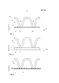
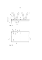
Фиг. 1 – поперечное сечение первой и второй металлических деталей, где между деталями нанесена композиция депрессорной присадки для снижения температуры плавления;FIG. 1 is a cross section of the first and second metal parts, where a depressant additive composition is applied between the parts to reduce the melting temperature;
Фиг. 2 - металлические детали по фиг. 1 во время нагревания;FIG. 2 - metal parts of FIG. 1 during heating;
Фиг. 3 - металлические детали по фиг. 1, когда образован шов;FIG. 3 - metal parts of FIG. 1 when a seam is formed;
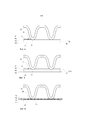
Фиг. 4 – поперечное сечение первой и второй металлических деталей, где композиция депрессорной присадки для снижения температуры плавления нанесена между компонентами и где вторая металлическая деталь упирается в первую металлическую деталь;FIG. 4 is a cross section of the first and second metal parts, where the depressant composition to reduce the melting temperature is applied between the components and where the second metal part abuts the first metal part;
Фиг. 5 - металлические детали по фиг. 4 во время нагревания;FIG. 5 - metal parts of FIG. 4 during heating;
Фиг. 6 - металлические детали по фиг. 4, когда образован шов;FIG. 6 - metal parts of FIG. 4 when a seam is formed;
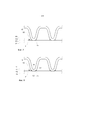
Фиг. 7 - металлические детали, когда шов образован и когда детали прижаты друг к другу во время образования шва;FIG. 7 - metal parts when the seam is formed and when the parts are pressed against each other during the formation of the seam;
Фиг. 8 - вид, соответствующий фиг. 7, где материал из обеих металлических деталей расплавился и образовал шов.FIG. 8 is a view corresponding to FIG. 7, where the material from both metal parts melted and formed a seam.
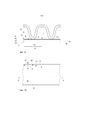
Фиг. 9 - вид, соответствующий фиг. 1, показывающий распределение точки контакта между металлическими деталями;FIG. 9 is a view corresponding to FIG. 1, showing the distribution of the contact point between metal parts;
Фиг. 10 - площадь точки контакта между металлическими деталями;FIG. 10 - the area of the contact point between the metal parts;
Фиг. 11 - вид, соответствующий фиг. 3, показывающий распределение шва между металлическими деталями;FIG. 11 is a view corresponding to FIG. 3, showing the distribution of the seam between metal parts;
Фиг. 12 - площадь поперечного сечения шва;FIG. 12 - the cross-sectional area of the seam;
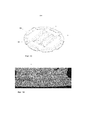
Фиг. 13 - прижимная плита, используемая в некоторых примерах, описывающих варианты соединения двух металлических деталей.FIG. 13 is a pressure plate used in some examples describing options for joining two metal parts.
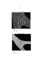
Фиг. 14 – фото поперечного сечения швов между плитой, показанной на фиг. 13, и плоской плитой.FIG. 14 is a cross-sectional photo of the joints between the plate shown in FIG. 13, and a flat stove.
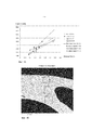
Фиг. 15 - диаграмма, где измеренная ширина шва построена как функция нанесенного количества композиции депрессорной присадки для снижения температуры плавления, включая линии тренда.FIG. 15 is a diagram where the measured weld width is plotted as a function of the applied amount of a depressant additive composition to lower the melting temperature, including trend lines.
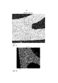
Фиг. 16-20 – поперечное сечение шва, исследованного сканирующим электронным микроскопом (SEM) и положения электронного сканирования; иFIG. 16-20 is a cross-sectional view of a seam examined by a scanning electron microscope (SEM) and electron scan position; and
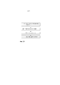
Фиг. 21 - блок-схема последовательности способа соединения первой и второй металлических деталей.FIG. 21 is a flowchart of a method for connecting the first and second metal parts.
ПОДРОБНОЕ ОПИСАНИЕDETAILED DESCRIPTION
На фиг. 1 показана первая металлическая деталь 11 и вторая металлическая деталь 12, где композиция 14 депрессорной присадки для снижения температуры плавления находится на поверхности 15 первой металлической детали 11. Вторая металлическая деталь 12 в контактной точке 16 находится в контакте с композицией 14 депрессорной присадки для снижения температуры плавления на поверхности 15. Для показанной второй металлической детали 12 первый выступ 28 находится в контакте с композицией 14 депрессорной присадки для снижения температуры плавления в контактной точке 16, а второй выступ 29 находится в контакте с композицией 14 депрессорной присадки для снижения температуры плавления в другой контактной точке 116. Первая металлическая деталь 11 изготовлена из металлического элемента, например из сплава на основе железа. Другие примеры подходящих металлических элементов, из которых может быть изготовлена первая металлическая деталь 11, приведены ниже. Вторая металлическая деталь 12 также изготовлена из металлического элемента, который может быть тем же металлическим элементом, из которого изготовлена первая металлическая деталь 11. На фиг. 1 первая металлическая деталь 11 и вторая металлическая деталь 12 еще не соединены.In FIG. 1 shows a
Для описания шва между первой металлической деталью 11 и второй металлической деталью 12 используются пять плоскостей P1-P5. Первая плоскость P1 определяет поверхность композиции 14 депрессорной присадки для снижения температуры плавления. Вторая плоскость P2 определяет поверхность 15 первой металлической детали 11, которая является "верхней" поверхностью 15 первой металлической детали 11. Это значит, что композиция 14 депрессорной присадки для снижения температуры плавления имеет толщину, которая соответствует расстоянию между первой плоскостью P1 и второй плоскостью P2 (поверхность 15). Следует отметить, что толщина композиции 14 депрессорной присадки для снижения температуры плавления на показанных чертежах сильно преувеличена. Реальная толщина, т.е. количество композиции 14 депрессорной присадки для снижения температуры плавления на поверхности 15, также как и состав композиции 14 депрессорной присадки для снижения температуры плавления подробно описаны ниже.To describe the seam between the
Третья плоскость P3 определяет поверхностный слой 21 первой металлической детали 11, и этот поверхностный слой 21 проходит от поверхности 15 и до третьей плоскости P3, которая расположена в первой металлической детали 11. Поэтому толщина поверхностного слоя 21 соответствует расстоянию между второй плоскостью Р2 (поверхность 15) и третьей плоскостью P3. Четвертая плоскость Р4 определяет нижнюю поверхность первой металлической детали 11. Толщина первой металлической детали 11 соответствует расстоянию между второй плоскостью P2 и четвертой плоскостью P4. Первая металлическая деталь 11 также имеет нижний слой 22, который является частью первой металлической детали 11, не включающей в себя поверхностный слой 21, и который проходит от третьей плоскости P3 к четвертой плоскости P4. Пятая плоскость P5 определяет базовую линию второй металлической детали 12, где первый выступ 28 и второй выступ 29 выступают от базовой линии в направлении к первой металлической детали 11.The third plane P3 defines the
Показанные формы первой металлической детали 11 и второй металлической детали 12 являются лишь иллюстративными формами и в равной степени возможны и другие формы. Например, металлические детали 11, 12 могут иметь изогнутые формы так, что плоскости P1-P5 не имеют форму плоских, двумерных поверхностей, а имеют форму изогнутых поверхностей. В частности, плоскости P2 и P3 не должны иметь резких линий и могут представлять постепенные переходы.The shapes shown of the
На фиг. 2 показаны металлические компоненты 11, 12, когда они нагреваются до температуры, выше которой композиция 14 депрессорной присадки для снижения температуры плавления заставляет поверхностный слой 21 расплавиться и образовать слой 210 расплавленного металла. Эта температура все еще остается ниже температуры плавления материалов в первой металлической детали 11 и во второй металлической детали 12. Излагая кратко, при нагреве металлических деталей 11, 12 фосфор и, необязательно, кремний, которые содержатся в композиции 14 депрессорной присадки для снижения температуры плавления, диффундируют в первую металлическую деталь 11 и заставляют ее расплавиться при температуре ниже температуры плавления материала первой металлической детали 11 (и второй металлической детали 12). Композицию 14 депрессорной присадки для снижения температуры плавления наносят на поверхность 15 в количестве, которое заставляет поверхностный слой 21 расплавиться и образовать слой 210 расплавленного металла. Таким образом, количество композиции 14 депрессорной присадки для снижения температуры плавления выбирают так, чтобы фосфор диффундировал только в поверхностный слой 21 (слишком большое количество фосфора может привести к плавлению всей первой металлической детали 11). Подходящие составы и количества композиции 14 депрессорной присадки для снижения температуры плавления описаны в примерах ниже. Металл в слое 210 расплавленного металла начинает течь, типично под действием капиллярного эффекта, к контактной точке 16 (и к другим подобным контактным точкам, таким как контактная точка 116).In FIG. 2,
На фиг. 3 показаны металлические компоненты 11, 12, когда вся композиция 14 депрессорной присадки для снижения температуры плавления диффундировала в первую металлическую деталь 11 и когда металл в слое 210 расплавленного металла стек к контактной точке 16, где теперь образовался шов 25. Теперь шов содержит металл, который ранее был частью первой металлической детали 11. Как можно видеть, на поверхности 15 первой металлической детали 11 больше нет композиции 14 депрессорной присадки для снижения температуры плавления, поскольку она диффундировала в первую металлическую деталь 11 и, типично, в некоторой степени во вторую металлическую деталь 12. Поскольку шов 25 образован из металла первой металлической детали 11, первая металлическая деталь 11 теперь, по меньшей мере локально, стала немного тоньше, чем до нагревания. Как можно видеть, первая металлическая деталь 11 теперь имеет верхнюю поверхность 15', которая не расположена на второй плоскости P2. Вместо этого верхняя поверхность теперь расположена ближе к четвертой плоскости P4. В общем, не весь металл из слоя 210 расплавленного металла стек к контактной точке 16 для образования шва 25, но часть его осталась на верхней поверхности первой металлической детали 11 и затвердела там одновременно с затвердеванием шва 25. Затвердевание происходит, когда температура понижена, но также и до снижения температуры, напр., поскольку фосфор в композиции депрессорной присадки для снижения температуры плавления постепенно диффундирует в материал первой металлической детали 11 и смешивается с ним. Физический процесс, лежащий в основе плавления металла в первой металлической детали 11 и последующего затвердевания, аналогичен процессу плавления и затвердевания, который происходит во время пайки твердым припоем. Однако по сравнению с обычной пайкой твердым припоем имеется большая разница, заключающаяся в том, что композиция 14 депрессорной присадки для снижения температуры расплава не содержит или содержит очень небольшое количество присадочного металла; вместо использования присадочного металла для создания шва 25, для этого используется металл из первой металлической детали 11. Необязательно, как будет описано ниже, для создания шва 25 можно использовать металл второй металлической детали 12.In FIG. 3,
Фиг. 4-6 соответствуют фиг. 1-3, с той лишь разницей, что вторая металлическая деталь 12 вдавлена в композицию 14 депрессорной присадки для снижения температуры плавления так, что она в основном находится в контакте с первой металлической деталью 11 или упирается в нее (между металлическими деталями 11, 12 все еще присутствует некоторое небольшое количество композиции 14 депрессорной присадки для снижения температуры плавления).FIG. 4-6 correspond to FIG. 1-3, with the only difference that the
Фиг. 7 соответствует фиг. 3 и 6 с той лишь разницей, что первая металлическая деталь 11 и вторая металлическая деталь 12 прижаты друг к другу во время образования шва 25. В результате вторая металлическая деталь 12 в положении шва 25 была "утоплена" в слой 210 расплавленного металла первой металлической детали 11.FIG. 7 corresponds to FIG. 3 and 6, with the only difference being that the
Фиг. 8 соответствует фиг. 7 и на ней материал и первой металлической детали 11, и второй металлической детали 12 был расплавлен и образован шов 25. На практике именно это происходит во время образования шва 25, особенно если первая металлическая деталь 11 и вторая металлическая деталь 12 изготовлены из одного и того же материала, поскольку вторая металлическая деталь 12 также находится в контакте с композицией депрессорной присадки для снижения температуры плавления.FIG. 8 corresponds to FIG. 7 and on it the material of both the
Перед нагреванием вторая металлическая деталь 12 имеет внешний контур, определенный линией L2. Во время нагревания поверхностный слой второй металлической детали 12 образует расплавленный поверхностный слой, где металл этого слоя течет к контактной точке 16 и образует там шов 25. Расплавленный поверхностный слой второй металлической детали 12 представлен слоем между линией L2 и L1, где линия L1 определяет границу, на которой металл второй металлической детали 12 не расплавлен.Before heating, the
Следует отметить, что между металлом первой металлической детали 11 и второй металлической детали 12, который расплавлен и который не расплавлен, резкой границы нет. Имеется постепенный переход от "расплавленного" металла к "нерасплавленному".It should be noted that between the metal of the
Фиг. 9 соответствует фиг. 1 и показывает распределение контактной точки 16 между первой металлической деталью 11 и второй металлической деталью 12. На фиг. 10 показаны те же металлические детали 11, 12, но как вид сверху и в первой плоскости P1. На фиг. 9 представлено поперечное сечение по линии А-А на фиг. 10.FIG. 9 corresponds to FIG. 1 and shows the distribution of the
Как можно видеть на чертежах, контактная точка 16 имеет распределение над композицией 14 депрессорной присадки для снижения температуры плавления на первой металлической детали 11, которое существенно больше распределения композиции 14 депрессорной присадки для снижения температуры плавления на поверхности 15. Распределение контактной точки 16 имеет площадь A2, которая существенно меньше, чем площадь A1 композиции 14 депрессорной присадки для снижения температуры плавления на поверхности 15. Площадь A1 содержит площадь A2. Площадь A1 проходит между двумя линиями L3, L4, которые расположены на соответствующей стороне от контактной точки 16. Линия L3 расположена между контактной точкой 16 и другой контактной точкой 116, поскольку расплавленный металл первой металлической детали 11 как правило течет к ближайшей контактной точке. Площадь A1 поверхности 15, на которую нанесена композиция 14 депрессорной присадки для снижения температуры плавления, по меньшей мере в 10 раз больше, чем площадь А2, определенная контактной точкой 16. Площадь A1 можно определить как площадь поверхности 15, на которую нанесена композиция 14 депрессорной присадки для снижения температуры плавления и из которой поступает металл для образования шва 25. Площадь A2 можно определить как площадь контактной точки 16, т.е. площадь контакта между композицией 14 депрессорной присадки для снижения температуры плавления и второй металлической деталью 12, необязательно, включая площадь контакта (если он имеется) между первой металлической деталью 11 и второй металлической деталью 12 в контактной точке 16. Площадь A1 как правило в 10 раз больше площади A2.As can be seen in the drawings, the
Фиг. 11 соответствует фиг. 3 и показывает площадь A3 поперечного сечения шва 25. Площадь A1 поверхности 15, на которую нанесена композиция 14 депрессорной присадки для снижения температуры плавления, по меньшей мере в 3 раза больше, чем площадь A3 поперечного сечения шва 25. На фиг. 12 показаны те же металлические детали 11, 12, но как вид сверху и во второй плоскости P2. На фиг. 11 приведено поперечное сечение по линии А-А на фиг. 12.FIG. 11 corresponds to FIG. 3 and shows the cross-sectional area A3 of the
Как можно видеть на чертежах, шов 25 имеет площадь A3 поперечного сечения, которая существенно меньше площади A1 композиции 14 депрессорной присадки для снижения температуры плавления на поверхности 15. Как и раньше, площадь A1 можно определить как площадь поверхности 15, на которую нанесена композиция 14 депрессорной присадки для снижения температуры плавления и из которой металл поступает для образования шва 25. Площадь A3 поперечного сечения шва 25 можно определить как наименьшую площадь, которую имеет шов 25 между первой металлической деталью 11 и второй металлической деталью 12. Площадь A3 поперечного сечения может иметь форму изогнутой поверхности. Очевидно, что площади A1 и A2 могут иметь форму изогнутой поверхности в зависимости от соответствующей формы первой металлической детали 11 и второй металлической детали 12.As can be seen in the drawings, the
В зависимости от формы соединяемых металлических деталей площадь, на которую наносится композиция депрессорной присадки для снижения температуры плавления, может быть по существу равна площади шва, который будет впоследствии образован.Depending on the shape of the metal parts to be joined, the area over which the depressant additive composition is applied to lower the melting temperature may be substantially equal to the area of the seam that will subsequently be formed.
Далее следует описание различных экспериментов и примеров, чтобы показать подходящие материалы для первой металлической детали 11, второй металлической детали 12, композиции 14 депрессорной присадки для снижения температуры плавления, количества применяемой композиции 14 депрессорной присадки для снижения температуры плавления, подходящие температуры нагрева, длительность нагрева и т.д. Так, результаты этих экспериментов и примеров используются для вышеописанных объектов, таких как первая металлическая деталь 11, вторая металлическая деталь 12, композиция 14 депрессорной присадки для снижения температуры плавления, контактная точка 16, шов 25 и пр., т.е. все описанные выше объекты могут содержать соответствующие признаки, описанные в связи с экспериментами и примерами, приведенными ниже. Далее композиция депрессорной присадки для снижения температуры плавления именуется "смесь". Металлическая деталь может именоваться "исходным металлом".The following is a description of various experiments and examples to show suitable materials for the
Было испытано некоторое количество композиций депрессорной присадки для снижения температуры плавления, т.е. композиций депрессорной присадки для снижения температуры точки плавления. Активным компонентом в композиции депрессорной присадки для снижения температуры плавления является фосфор (P). В качестве источника фосфора выбирались соединения фосфора. Эти соединения включают в себя Fe3P, NiP и Mn3P2, при этом Mn3P2 является смесью MnP и Mn2P. Также можно использовать другие соединения, включающие в себя фосфор, их лишь следует проверить на предмет полезности и по результату, который они обеспечивают, так же, как это сделано для Fe3P, NiP и Mn3P2 и очерчено ниже.A number of depressant compositions have been tested to reduce the melting point, i.e. depressant compositions to lower the melting point. The active ingredient in the depressant composition to lower the melting point is phosphorus (P). Phosphorus compounds were selected as the source of phosphorus. These compounds include Fe 3 P, NiP, and Mn 3 P 2 , while Mn 3 P 2 is a mixture of MnP and Mn 2 P. Other compounds including phosphorus can also be used, they should only be checked for utility and the result they provide is the same as that for Fe 3 P, NiP and Mn 3 P 2 and is outlined below.
Fe3P, также именуемый фосфидом железа, является обычным соединением, которое было получено от компании Alfa Aesar с CAS-номером (Chemical Abstracts Service) 12023-53-9 и MDL-номером (Molecular Design Limited) MFCD00799762.Fe 3 P, also referred to as iron phosphide, is a common compound that was obtained from Alfa Aesar with a CAS number (Chemical Abstracts Service) 12023-53-9 and an MDL number (Molecular Design Limited) MFCD00799762.
Mn3P2, также именуемый фосфид марганца, является обычным соединением, которое было получено от компании Alfa Aesar с CAS-номером 12263-33-1 и MDL-номером MFCD00064736.Mn 3 P 2 , also referred to as manganese phosphide, is a common compound obtained from Alfa Aesar with CAS number 12263-33-1 and MDL number MFCD00064736.
NiP, также именуемый фосфидом никеля, является обычным соединением, которое было плакировано на соединяемую металлическую деталь. Соединяемая металлическая деталь также именуется основной металл или основной материал. Плакирование осуществлялось обычным способом нанесения фосфида никеля, который практикуется, например, компанией Brink Förnicklingsfabriken AB из Norrköping, Швеция.NiP, also referred to as nickel phosphide, is a common compound that has been plated onto a joined metal part. The metal part to be joined is also referred to as base metal or base material. The cladding was carried out by the usual method of applying nickel phosphide, which is practiced, for example, by Brink Förnicklingsfabriken AB of Norrköping, Sweden.
Для некоторых примеров использовался Si, или кремний. Кремний является обычным веществом, полученным от компании Alfa Aesar, и именуется "кремний порошковый, кристаллический, 325 меш, 99,5% ( на основе металла)" с номерами CAS 7440-21-3 и MDL MFCD00085311.For some examples, Si or silicon was used. Silicon is a common substance obtained from Alfa Aesar and is referred to as "powder silicon, crystalline, 325 mesh, 99.5% (based on metal)" with CAS numbers 7440-21-3 and MDL MFCD00085311.
При рассмотрении атомного состава соединений, применяя атомные вес и используя известные способы расчета, можно определить, что Fe3P содержит 16% по массе Р (фосфора), а Mn3P2 содержит 27% по массе фосфора.When considering the atomic composition of compounds, using atomic weight and using known calculation methods, it can be determined that Fe 3 P contains 16% by weight of P (phosphorus), and Mn 3 P 2 contains 27% by weight of phosphorus.
Для нанесения Fe3P и Mn3P2 на соединяемые металлические детали использовалось связующее. Связующее (полимер и растворитель) продается компанией Wall Colmonoy под наименованием Nicorobraz S-20 (S-20). Образец связующего был помещен на металлическую пластину и высушен при 22°C в течение 24 ч. Масса образца была 0,56 г до сушки и 0,02 г после сушки. Таким образом, 3,57% по массе связующего - это компоненты, оставшиеся после сушки. Была приготовлена композиция депрессорной присадки для снижения температуры плавления, в Mn3P2 и Si образовали компонент депрессорной присадки для снижения температуры плавления (компонент депрессорной присадки для снижения температуры точки плавления) и где связующее S-20 являлось связующим компонентом. Приготовление осуществлялось путем смешивания Mn3P2 и Si, после чего добавлялось связующее S-20. Было приготовлено два варианта композиции депрессорной присадки для снижения температуры плавления с разным количеством Si, названные А1 Mn3P2 (А1) и В1 Mn3P2 (В1), как показано в таблице 1.A binder was used to apply Fe 3 P and Mn 3 P 2 to the metal parts to be joined. A binder (polymer and solvent) is sold by Wall Colmonoy under the name Nicorobraz S-20 (S-20). A binder sample was placed on a metal plate and dried at 22 ° C for 24 hours. The mass of the sample was 0.56 g before drying and 0.02 g after drying. Thus, 3.57% by weight of the binder are the components remaining after drying. A depressant additive composition was prepared to lower the melting point, in Mn 3 P 2 and Si, a depressant additive component was formed to lower the melting point (depressant additive component to lower the melting point), and where S-20 binder was the binder component. The preparation was carried out by mixing Mn 3 P 2 and Si, and then the binder was added S-20. Two variants composition depressant to lower the melting temperature were prepared with varying amounts of Si, Mn named A1 2 3 P (A1) and B1 Mn 3 P 2 (B1) as shown in Table 1.
Композиции A1 и A2 наносились на плоские круглые тестовые образцы из нержавеющей стали типа 317L (сорт стали по SAE) и диаметром 42 мм.Compositions A1 and A2 were applied to flat round test samples of stainless steel type 317L (grade of steel according to SAE) and a diameter of 42 mm.
На каждый тестовый образец был помещена другой кусок из другого материала, 254 SMO (сорт стали по SAE). Этот другой кусок показан на фиг. 13 и имеет форму круглой штампованной пластины 150 диаметром 42 мм и толщиной 0,4 мм. Штампованная пластина 150 имеет две штампованных консоли v и h, каждая из которых имеет длину приблизительно 20 мм. Когда кусок с консолями был помещен на плоскую пластину, были образованы контактные точки в местах, где консоли куска 150 упирались в другой, плоский кусок.A different piece of another material, 254 SMO (SAE grade), was placed on each test piece. This other piece is shown in FIG. 13 and has the shape of a round stamped
Эти куски, т.е. плоский круглый кусок и штампованная пластина, именуются образцом, и несколько таких образцов подвергались термообработке в течение 2 часов в вакууме при разных температурах для каждого образца. В таблице 2 показано количество композиций, использовавшееся для образцов.These pieces, i.e. a flat round piece and a stamped plate are referred to as a sample, and several such samples were heat treated for 2 hours in vacuum at different temperatures for each sample. Table 2 shows the number of compositions used for the samples.
Для образцов с A1:1 до A1:3 и образцов с B1:1 до B1:3 термообработка заключалась в выдерживании образцов при температуре 1120°C в течение 2 часов в вакууме.For samples from A1: 1 to A1: 3 and samples from B1: 1 to B1: 3, the heat treatment consisted of holding the samples at a temperature of 1120 ° C for 2 hours in vacuum.
Для образцов с A1:4 по A1:6 и образцов с B1:4 по B1:6 термообработка заключалась в выдерживании образцов при температуре 1140°C в течение 2 часов в вакууме.For samples A1: 4 through A1: 6 and samples B1: 4 through B1: 6, the heat treatment consisted of holding the samples at 1140 ° C for 2 hours in vacuum.
A1 означает композицию A1 Mn3P2, а B1 означает композицию B1 Mn3P2. Числа после позиции А1 и, соответственно, В1 указывают на разные образцы, представленные в таблице 2. В этой таблице показана масса образцов, которая включает в себя массу компонента депрессорной присадки для снижения температуры плавления и массу сухого связующего компонента.A1 means composition A1 Mn 3 P 2 , and B1 means composition B1 Mn 3 P 2 . The numbers after position A1 and, respectively, B1 indicate the different samples shown in table 2. This table shows the mass of the samples, which includes the mass of the depressant additive component to lower the melting point and the mass of the dry binder component.
После термообработки образцам давали остыть до комнатной температуры (22°C) и наблюдали, что два куска образца были соединены вдоль длин консолей на штампованной пластине 150, т.е. образец имел швы вдоль консолей. Образцы разрезали поперек швов в двух сечениях и каждый шов измеряли по самому широкому сечению Х, как показано на фиг. 14. Результаты представлены в таблице 3 и показаны на диаграмме на фиг. 15, где ширина шва отложена как функция нанесенного количества композиции депрессорной присадки для снижения температуры плавления.After heat treatment, the samples were allowed to cool to room temperature (22 ° C) and it was observed that two pieces of the sample were connected along the lengths of the arms on a stamped
Затем швы подверглись металлургическим исследованиям. Эти исследования проводились на разрезанных поперечных сечениях швов с помощью сканирующего электронного микроскопа методом энергодисперсионной рентгеновской спектроскопии(SEM-EDX), который является известным и коммерчески доступным сканирующим электронным микроскопом с детектором рентгеновского излучения. На фиг. 16 показаны положения трех измерений образца A1-6, а в таблице 4 приведены результаты измерений.Then the seams were subjected to metallurgical studies. These studies were carried out on cut cross-sections of the seams using a scanning electron microscope using energy dispersive X-ray spectroscopy (SEM-EDX), which is a well-known and commercially available scanning electron microscope with an X-ray detector. In FIG. Figure 16 shows the positions of the three measurements of sample A1-6, and table 4 shows the measurement results.
Исследования показывают, что швы содержат по меньшей мере 90% по массе металла, который до нагревания был частью первой металлической детали и второй металлической детали, т.е. кусками образца. Это легко определяется, поскольку Mn и P вместе представляют менее 2,2% по массе.Studies show that the seams contain at least 90% by weight of the metal, which before heating was part of the first metal part and the second metal part, i.e. pieces of sample. This is easily determined since Mn and P together represent less than 2.2% by weight.
Подобные исследования также проводились на образце B1-6. На фиг. 17 показаны положения трех измерений для образца B1-6, а в таблице 5 сведены результаты измерений.Similar studies were also conducted on sample B1-6. In FIG. 17 shows the positions of three measurements for sample B1-6, and table 5 summarizes the measurement results.
Исследования показывают, что швы содержат по меньшей мере 90% по массе металла, который до нагревания был частью первой металлической детали и второй металлической детали, т.е. кусками образца. Это легко определяется, поскольку Mn и P вместе представляют менее 4,2% по массе.Studies show that the seams contain at least 90% by weight of the metal, which before heating was part of the first metal part and the second metal part, i.e. pieces of sample. This is easily determined since Mn and P together represent less than 4.2% by weight.
На следующие тестовые куски из нержавеющей стали типа 316, именуемой как "316", диаметром 412 мм были нанесены три разных композиции депрессорной присадки для снижения температуры плавления (по одной композиции на соответствующий кусок): i) Mn3P2, ii) NiP, плакированный на 316, и iii) NiP, плакированный на 316, вместе с Si как депрессорная присадка для снижения точки плавления. Толщина плакированного NiP равна 50 мкм. -0,15 г Si нанесены обычным окрашиванием. На каждый кусок помещался штампованный кусок, подобный показанному на фиг. 13 и изготовленный из материала 254 SMO. Эти куски составляли образцы, которые подвергались термообработке в течение 2 часов в вакууме при 1120°C. Между деталями образовались швы.The following test pieces of 316 stainless steel, referred to as "316", 412 mm in diameter, were coated with three different depressant compositions to lower the melting temperature (one composition per corresponding piece): i) Mn 3 P 2 , ii) NiP, plated at 316, and iii) NiP plated at 316, together with Si as a depressant to reduce the melting point. The clad NiP thickness is 50 μm. -0.15 g Si applied by conventional staining. A stamped piece similar to that shown in FIG. 13 and made of material 254 SMO. These pieces were samples that were heat treated for 2 hours in vacuo at 1120 ° C. Seams formed between the parts.
В таблице 6 показан анализ разрезанного поперечного сечения швов с использованием сканирующего электронного микроскопа методом энергодисперсионной рентгеновской спектроскопии для образца, плакированного 50 мкм NiP. Из результатов следует, что шов содержит по меньшей мере 20% металла, который до нагревания был частью любой из первого куска (первая металлическая деталь) или второго куска (вторая металлическая деталь). На фиг. 18 показано положение измерений на шве.Table 6 shows the analysis of the cut cross-section of the seams using a scanning electron microscope using energy dispersive x-ray spectroscopy for a sample plated with 50 μm NiP. From the results it follows that the seam contains at least 20% metal, which before heating was part of any of the first piece (first metal part) or the second piece (second metal part). In FIG. 18 shows the measurement position on the seam.
В таблице 7 приведен анализ среза поперечного сечения швов с использованием SEM-EDX для образца, плакированного 50 мкм NiP, где на покрытую поверхность было нанесено прибл. 0,15 г Si(окрашиванием). Из результатов следует, что шов содержит больше металла по сравнению с тестом, где Si не использовался. Более высокое количество Si наиболее вероятно повысило количество металла в шве, который поступил из тестовых кусков. На фиг. 19 показаны положения измерений шва.Table 7 summarizes the cross-sectional sectional analysis of the seams using SEM-EDX for a sample plated with 50 μm NiP, where approx. 0.15 g Si (staining). From the results it follows that the seam contains more metal compared to the test where Si was not used. Higher amounts of Si most likely increased the amount of metal in the seam that came from the test pieces. In FIG. 19 shows the seam measurement positions.
В табл. 8 показан анализ среза поперечного сечения швов с использованием SEM-EDX для образца с Mn3P2. Mn3P2 смешивался в пропорции 50:50 (по массе) со связующим S-20, но Si не использовался. Было нанесено 0,2 г (после сушки связующего компонента). Из результатов следует, что шов содержит по меньшей мере 80% по массе металла, который перед соединением был частью соединяемых изделий. На фиг. 20 показаны положения измерений спектра 1 в шве.In the table. Figure 8 shows a cross sectional analysis of welds using SEM-EDX for a sample with Mn 3 P 2 . Mn 3 P 2 was mixed in a proportion of 50:50 (by weight) with a binder S-20, but Si was not used. 0.2 g was applied (after drying the binder component). From the results it follows that the seam contains at least 80% by weight of the metal, which before joining was part of the connected products. In FIG. 20 shows the measurement positions of spectrum 1 in the seam.
СПОСОБMETHOD
На фиг. 21 показана блок-схема последовательности способа соединения первой и второй металлических деталей. Металлические детали могут быть изготовлены из разных материалов, как описано выше.In FIG. 21 is a flowchart of a method for connecting the first and second metal parts. Metal parts can be made of different materials, as described above.
На первом этапе 201 композицию депрессорной присадки для снижения температуры плавления наносят на поверхность одной из металлических деталей (здесь - первой металлической детали). Само нанесение может осуществляться обычными технологиями, например распылением или окрашиванием, если композиция депрессорной присадки для снижения температуры плавления содержит связующий компонент, или физическим (PVD), или химическим (CVD) осаждением из паровой фазы, если связующий компонент не используется.In the first step 201, a depressant composition is applied to lower the melting temperature on the surface of one of the metal parts (here, the first metal part). The application itself can be carried out by conventional technologies, for example by spraying or staining, if the depressant additive composition to reduce the melting point contains a binder component, either by physical (PVD) or chemical (CVD) vapor deposition if the binder component is not used.
На следующем этапе 202 вторую металлическую деталь вводят в контакт с композицией депрессорной присадки для снижения температуры плавления в точке контакта на поверхности. Это может осуществляться вручную или автоматически, применяя обычные автоматизированные производственные системы.In the next step 202, the second metal part is brought into contact with the depressant composition to lower the melting point at the contact point on the surface. This can be done manually or automatically, using conventional automated production systems.
На следующем этапе 303 металлические детали нагревают до температуры выше 1000°C. Точную температуру можно найти в примерах, приведенных выше. Во время нагревания поверхность по меньшей мере первой металлической детали плавится и, вместе с компонентом депрессорной присадки для снижения температуры плавления, образует слой расплавленного металла, который контактирует со второй металлической деталью в точке контакта между первой металлической деталь и второй металлической деталь. Когда это происходит, металл и слой расплавленного металла текут по направлению к точке контакта.In a next step 303, metal parts are heated to temperatures above 1000 ° C. The exact temperature can be found in the examples above. During heating, the surface of at least the first metal part melts and, together with the depressant additive component to lower the melting point, forms a layer of molten metal that contacts the second metal part at the point of contact between the first metal part and the second metal part. When this happens, the metal and the molten metal layer flow towards the point of contact.
На последнем этапе 204 допускают затвердевание слоя расплавленного металла так, чтобы в точке контакта получить шов, т.е. металл, который перетек к точке контакта, затвердевает. Процесс затвердевания типично включает в себя понижение температуры до нормальной комнатной температуры. Однако затвердевание также происходит во время физического процесса перераспределения компонентов (фосфора и, необязательно, кремния) в области шва до понижения температуры.At the last step 204, a layer of molten metal is allowed to solidify so that a seam is obtained at the contact point, i.e. metal that flows to the point of contact hardens. The curing process typically involves lowering the temperature to normal room temperature. However, solidification also occurs during the physical process of the redistribution of components (phosphorus and, optionally, silicon) in the weld region until the temperature decreases.
Из вышеприведенного описания следует, что хотя выше были описаны различные варианты изобретения, изобретение не ограничивается ими, но может быть реализовано другими способами в пределах объема, определенного приложенной формулой. Различные композиции депрессорной присадки для снижения температуры плавления также можно комбинировать с разными металлами металлических деталей.From the above description it follows that although various embodiments of the invention have been described above, the invention is not limited to them, but can be implemented in other ways within the scope defined by the attached claims. Various depressant additives compositions can also be combined with different metals of metal parts to lower the melting point.
Claims (34)
Applications Claiming Priority (3)
| Application Number | Priority Date | Filing Date | Title |
|---|---|---|---|
| EP13186257.5 | 2013-09-26 | ||
| EP13186257.5A EP2853333B1 (en) | 2013-09-26 | 2013-09-26 | Method of joining metal parts using a melting depressant layer |
| PCT/EP2014/069240 WO2015043945A1 (en) | 2013-09-26 | 2014-09-10 | Method for joining metal parts |
Publications (1)
| Publication Number | Publication Date |
|---|---|
| RU2633171C1 true RU2633171C1 (en) | 2017-10-11 |
Family
ID=49230663
Family Applications (1)
| Application Number | Title | Priority Date | Filing Date |
|---|---|---|---|
| RU2016106302A RU2633171C1 (en) | 2013-09-26 | 2014-09-10 | Method of joining metal parts |
Country Status (25)
| Country | Link |
|---|---|
| US (2) | US10323890B2 (en) |
| EP (2) | EP2853333B1 (en) |
| JP (2) | JP6250165B2 (en) |
| KR (3) | KR102123503B1 (en) |
| CN (2) | CN105555452B (en) |
| AR (2) | AR100759A1 (en) |
| AU (1) | AU2014327554B2 (en) |
| BR (1) | BR112016001931B1 (en) |
| CA (1) | CA2916342C (en) |
| CL (1) | CL2015003755A1 (en) |
| DK (2) | DK2853333T3 (en) |
| ES (2) | ES2756850T3 (en) |
| IL (1) | IL243428A0 (en) |
| MX (1) | MX2015017579A (en) |
| MY (1) | MY186028A (en) |
| NZ (1) | NZ715303A (en) |
| PH (1) | PH12016500192A1 (en) |
| PL (1) | PL2853333T3 (en) |
| PT (1) | PT2853333T (en) |
| RU (1) | RU2633171C1 (en) |
| SA (1) | SA516370799B1 (en) |
| SG (1) | SG11201600189SA (en) |
| SI (2) | SI2853333T1 (en) |
| TW (1) | TWI602636B (en) |
| WO (2) | WO2015043945A1 (en) |
Cited By (1)
| Publication number | Priority date | Publication date | Assignee | Title |
|---|---|---|---|---|
| RU2784149C1 (en) * | 2019-05-29 | 2022-11-23 | Альфа Лаваль Корпорейт Аб | Method for joining metal parts |
Families Citing this family (14)
| Publication number | Priority date | Publication date | Assignee | Title |
|---|---|---|---|---|
| DK2644312T3 (en) * | 2012-03-28 | 2019-02-25 | Alfa Laval Corp Ab | Hitherto unknown soldering concept |
| ES2756850T3 (en) * | 2013-09-26 | 2020-04-27 | Alfa Laval Corp Ab | Method of joining metal parts using a melting point depressant layer |
| KR101780108B1 (en) * | 2015-06-22 | 2017-09-19 | 두산중공업 주식회사 | Plate for heat exchanger for transition liquid phase bonding |
| EP3527320B1 (en) * | 2016-03-31 | 2020-12-23 | Alfa Laval Corporate AB | Method for joining heat transfer plates of a plate heat exchanger |
| CN109641297A (en) * | 2016-09-01 | 2019-04-16 | 林德股份公司 | For manufacturing the method with the plate heat exchanger block for the brazing material being targetedly applied on especially fin and strip of paper used for sealing |
| US10883935B2 (en) | 2016-09-15 | 2021-01-05 | Arylla Inc. | System and method of product authentication |
| SE540665C2 (en) * | 2016-10-07 | 2018-10-09 | Alfa Laval Corp Ab | Titanium plate heat exchanger |
| CN107333217A (en) * | 2017-07-20 | 2017-11-07 | 惠州超声音响有限公司 | A kind of high pitch loudspeaker for improving throat taps mounting structure |
| KR102524340B1 (en) * | 2018-02-22 | 2023-04-25 | 삼성디스플레이 주식회사 | Flexible display device and method of manufacturing of the same |
| US11065628B2 (en) | 2018-07-09 | 2021-07-20 | Kennametal Inc. | Centrifuge tile assembly |
| CN109848499B (en) * | 2019-03-08 | 2021-05-14 | 西安远航真空钎焊技术有限公司 | Preparation method of complex heat exchanger core |
| SE543405C2 (en) | 2019-05-29 | 2021-01-05 | Alfa Laval Corp Ab | Method for joining metal parts |
| US11465227B2 (en) * | 2021-02-12 | 2022-10-11 | GM Global Technology Operations LLC | System and method for manufacturing high-strength bonded metal sheets for a battery cell |
| CN113601115B (en) * | 2021-08-10 | 2022-05-31 | 西安远航真空钎焊技术有限公司 | Preparation method of honeycomb trapezoidal corrugated heat exchange plate component |
Citations (4)
| Publication number | Priority date | Publication date | Assignee | Title |
|---|---|---|---|---|
| SU659326A1 (en) * | 1977-08-22 | 1979-04-30 | Ордена Ленина И Трудового Красного Знамени Институт Электросварки Имени Е.О.Патона Ан Украинской Сср | Solder for soldering stainless refractory steels and nickel-base alloys |
| RU2096150C1 (en) * | 1993-04-13 | 1997-11-20 | Научно-производственное предприятие "Гамма" | Alloy solder for soldering stainless steels and nickel-based alloys |
| RU2167751C2 (en) * | 1995-05-22 | 2001-05-27 | Элайдсигнал Инк. | Nickel-chrome base hard solders |
| WO2008060225A1 (en) * | 2006-11-17 | 2008-05-22 | Alfa Laval Corporate Ab | Brazing material, a method of brazing, a brazed article and a paste comprising this brazing material |
Family Cites Families (44)
| Publication number | Priority date | Publication date | Assignee | Title |
|---|---|---|---|---|
| US2289365A (en) * | 1941-08-29 | 1942-07-14 | Henry S Jerabek | Iron-phosphorus-silicon alloy |
| US3515950A (en) | 1968-02-14 | 1970-06-02 | Mallory & Co Inc P R | Solderable stainless steel |
| GB1533044A (en) | 1976-02-27 | 1978-11-22 | British Steel Corp | Hardfacing by welding |
| US4075009A (en) | 1976-04-30 | 1978-02-21 | Alloy Metals, Inc. | Nickel base brazing alloy |
| JPS55111930A (en) | 1979-02-21 | 1980-08-29 | Canon Inc | Electromagnetic release device |
| US5120931A (en) | 1991-04-12 | 1992-06-09 | The Lincoln Electric Company | Electrode and flux for arc welding stainless steel |
| US5267390A (en) * | 1991-04-15 | 1993-12-07 | Yang Duck J | Organic vapor deposition process for corrosion protection of prestamped metal substrates |
| NO175543C (en) * | 1992-11-18 | 1994-10-26 | Elkem As | Silicon-based alloy, process for making such alloy, and process for producing consolidated products from silicon-based alloy |
| JPH08271175A (en) | 1995-03-29 | 1996-10-18 | Nippon Steel Corp | Stainless steel plate laminated heat exchanger, and its production |
| WO1997043082A1 (en) | 1996-05-14 | 1997-11-20 | Alliedsignal Inc. | Nickel-chromium-based brazing alloys |
| JP3243184B2 (en) | 1996-07-12 | 2002-01-07 | 新日本製鐵株式会社 | Alloy foil for liquid phase diffusion bonding that can be bonded in oxidizing atmosphere |
| JPH11287576A (en) | 1998-03-31 | 1999-10-19 | Hisaka Works Ltd | Brazing plate type heat exchanger |
| SE513540C2 (en) * | 1998-06-16 | 2000-09-25 | Alfa Laval Ab | A method of producing a plate heat exchanger as well as a plate heat exchanger |
| JP2000225491A (en) * | 1999-02-05 | 2000-08-15 | Zexel Corp | Flux mixture for brazing aluminum member, brazing method and heat exchanger |
| SE513784C2 (en) | 1999-03-09 | 2000-11-06 | Alfa Laval Ab | Permanently joined plate heat exchanger |
| FR2816045B1 (en) * | 2000-10-27 | 2003-09-19 | Air Liquide | METHOD OF MANUFACTURING A HEAT EXCHANGER WITH BRAZED PLATES, AND HEAT EXCHANGER OBTAINED BY THIS PROCESS |
| SE523855C2 (en) | 2000-11-10 | 2004-05-25 | Alfa Laval Corp Ab | Iron-based brazing material for joining elm and soldered product made herewith |
| CN1246118C (en) | 2000-12-28 | 2006-03-22 | 布拉景有限公司 | Plate type heat exchanger and method for manufacture thereof |
| SE519062C2 (en) * | 2001-05-03 | 2003-01-07 | Alfa Laval Corp Ab | Ways of soldering thin heat exchanger plates and soldered plate heat exchangers prepared according to the method |
| SE524928C2 (en) | 2001-06-05 | 2004-10-26 | Alfa Laval Corp Ab | Iron-based brazing material for joining elements through brazing and brazed product made herewith |
| JP3458849B2 (en) * | 2001-08-03 | 2003-10-20 | 株式会社日立製作所 | Cobalt-based alloys and valves and reactor plants using these alloys |
| US20060102696A1 (en) * | 2001-11-21 | 2006-05-18 | Graham Michael E | Layered products for fluxless brazing of substrates |
| US8776371B2 (en) * | 2002-05-03 | 2014-07-15 | Alfa Laval Corporate Ab | Method of brazing thin heat exchanging plates and brazed plate heat exchanger produced according to the method |
| CN2566214Y (en) | 2002-09-04 | 2003-08-13 | 仇世达 | Cold-hot exchanger |
| JP2005000940A (en) | 2003-06-10 | 2005-01-06 | Toshiba Corp | Brazing filler of multi-layer lamination type, and method for brazing-repair |
| JP2005088062A (en) | 2003-09-18 | 2005-04-07 | Calsonic Kansei Corp | Brazing method for stainless steel component |
| US7510621B2 (en) * | 2004-09-22 | 2009-03-31 | General Motors Corporation | Conductive adhesive bonding |
| SE529913C2 (en) * | 2005-05-26 | 2008-01-08 | Alfa Laval Corp Ab | Brazing articles of stainless steel, e.g. large heat exchanger involves applying an iron-based brazing filler material to parts of stainless steel, heating the parts, and providing brazed areas with specific average hardness |
| PT1888294E (en) | 2005-05-26 | 2014-07-28 | Alfa Laval Corp Ab | A method of brazing articles of stainless steel |
| US20070164088A1 (en) * | 2006-01-18 | 2007-07-19 | Kam Dianatkhah | Brazing process for stainless steel heat exchangers |
| TWM298107U (en) | 2006-03-03 | 2006-09-21 | Kaori Heat Treat Co Ltd | Improved fluid passage structure for plate-type heat exchanger |
| US7392930B2 (en) * | 2006-07-06 | 2008-07-01 | Sulzer Metco (Us), Inc. | Iron-based braze filler metal for high-temperature applications |
| ATE417691T1 (en) * | 2006-08-17 | 2009-01-15 | Atotech Deutschland Gmbh | METHOD FOR JOINING WORKPIECES MADE OF STAINLESS STEEL, NICKEL OR NICKEL ALLOYS USING A JOINING LAYER CONSISTING OF A NICKEL-PHOSPHORUS ALLOY; METHOD FOR PRODUCING A MICROSTRUCTURED COMPONENT USING SUCH A METHOD |
| US20090016953A1 (en) * | 2007-07-11 | 2009-01-15 | Kenneth Scott Weil | High-Temperature Air Braze Filler Materials And Processes For Preparing And Using Same |
| CN201322570Y (en) | 2008-12-18 | 2009-10-07 | 江苏唯益换热器有限公司 | Heat exchange plate |
| CN102308177B (en) | 2009-02-04 | 2013-05-08 | 阿尔法拉瓦尔股份有限公司 | Plate heat exchanger |
| KR101812618B1 (en) * | 2009-09-18 | 2017-12-27 | 회가내스 아베 (피유비엘) | Iron-chromium based brazing filler metal |
| WO2012081346A1 (en) * | 2010-12-16 | 2012-06-21 | 福田金属箔粉工業株式会社 | Nickel-based brazing filler metal with excellent heat resistance |
| KR101318914B1 (en) * | 2011-08-25 | 2013-10-16 | 서울시립대학교 산학협력단 | Brazing filler metel alloy composite for preventing discolor |
| FR2987570B1 (en) | 2012-03-02 | 2014-04-18 | Snecma | METHOD FOR ASSEMBLING TWO METAL PIECES BY BRAZING |
| DK2644312T3 (en) * | 2012-03-28 | 2019-02-25 | Alfa Laval Corp Ab | Hitherto unknown soldering concept |
| WO2014022625A1 (en) | 2012-08-02 | 2014-02-06 | Wall Colmonoy Corporation | Nickel-based brazing filler metal powder for brazing base metal parts with reduced erosion |
| FR3010655B1 (en) * | 2013-09-18 | 2015-09-04 | Michelin & Cie | PNEUMATIC COMPRISING FLANK REINFORCING FRAME |
| ES2756850T3 (en) * | 2013-09-26 | 2020-04-27 | Alfa Laval Corp Ab | Method of joining metal parts using a melting point depressant layer |
-
2013
- 2013-09-26 ES ES13186257T patent/ES2756850T3/en active Active
- 2013-09-26 PT PT131862575T patent/PT2853333T/en unknown
- 2013-09-26 SI SI201331595T patent/SI2853333T1/en unknown
- 2013-09-26 DK DK13186257T patent/DK2853333T3/en active
- 2013-09-26 PL PL13186257T patent/PL2853333T3/en unknown
- 2013-09-26 EP EP13186257.5A patent/EP2853333B1/en active Active
- 2013-09-27 SI SI201330846T patent/SI2853334T1/en unknown
- 2013-09-27 EP EP13186388.8A patent/EP2853334B1/en active Active
- 2013-09-27 ES ES13186388.8T patent/ES2654532T3/en active Active
- 2013-09-27 DK DK13186388.8T patent/DK2853334T3/en active
-
2014
- 2014-08-28 TW TW103129628A patent/TWI602636B/en active
- 2014-09-10 NZ NZ715303A patent/NZ715303A/en unknown
- 2014-09-10 US US14/903,464 patent/US10323890B2/en active Active
- 2014-09-10 US US14/910,773 patent/US10180292B2/en active Active
- 2014-09-10 MX MX2015017579A patent/MX2015017579A/en unknown
- 2014-09-10 SG SG11201600189SA patent/SG11201600189SA/en unknown
- 2014-09-10 JP JP2016533935A patent/JP6250165B2/en active Active
- 2014-09-10 CN CN201480052777.0A patent/CN105555452B/en active Active
- 2014-09-10 KR KR1020187025015A patent/KR102123503B1/en active IP Right Grant
- 2014-09-10 KR KR1020167010460A patent/KR101874214B1/en active IP Right Grant
- 2014-09-10 BR BR112016001931-8A patent/BR112016001931B1/en active IP Right Grant
- 2014-09-10 AU AU2014327554A patent/AU2014327554B2/en active Active
- 2014-09-10 CN CN201480052749.9A patent/CN105829002B/en active Active
- 2014-09-10 WO PCT/EP2014/069240 patent/WO2015043945A1/en active Application Filing
- 2014-09-10 RU RU2016106302A patent/RU2633171C1/en active
- 2014-09-10 KR KR1020167010585A patent/KR20160060707A/en not_active Application Discontinuation
- 2014-09-10 MY MYPI2016701071A patent/MY186028A/en unknown
- 2014-09-10 JP JP2016517375A patent/JP6290384B2/en active Active
- 2014-09-10 CA CA2916342A patent/CA2916342C/en active Active
- 2014-09-10 WO PCT/EP2014/069239 patent/WO2015043944A1/en active Application Filing
- 2014-09-25 AR ARP140103554A patent/AR100759A1/en active IP Right Grant
- 2014-09-25 AR ARP140103556A patent/AR097770A1/en active IP Right Grant
-
2015
- 2015-12-29 CL CL2015003755A patent/CL2015003755A1/en unknown
- 2015-12-31 IL IL243428A patent/IL243428A0/en active IP Right Grant
-
2016
- 2016-01-27 PH PH12016500192A patent/PH12016500192A1/en unknown
- 2016-03-23 SA SA516370799A patent/SA516370799B1/en unknown
Patent Citations (5)
| Publication number | Priority date | Publication date | Assignee | Title |
|---|---|---|---|---|
| SU659326A1 (en) * | 1977-08-22 | 1979-04-30 | Ордена Ленина И Трудового Красного Знамени Институт Электросварки Имени Е.О.Патона Ан Украинской Сср | Solder for soldering stainless refractory steels and nickel-base alloys |
| RU2096150C1 (en) * | 1993-04-13 | 1997-11-20 | Научно-производственное предприятие "Гамма" | Alloy solder for soldering stainless steels and nickel-based alloys |
| RU2167751C2 (en) * | 1995-05-22 | 2001-05-27 | Элайдсигнал Инк. | Nickel-chrome base hard solders |
| WO2008060225A1 (en) * | 2006-11-17 | 2008-05-22 | Alfa Laval Corporate Ab | Brazing material, a method of brazing, a brazed article and a paste comprising this brazing material |
| US20090305078A1 (en) * | 2006-11-17 | 2009-12-10 | Alfa Laval Corporate Ab | Brazing Material, a Method of Brazing, a Brazed Article and a Paste Comprising This Brazing Material |
Cited By (1)
| Publication number | Priority date | Publication date | Assignee | Title |
|---|---|---|---|---|
| RU2784149C1 (en) * | 2019-05-29 | 2022-11-23 | Альфа Лаваль Корпорейт Аб | Method for joining metal parts |
Also Published As
Similar Documents
| Publication | Publication Date | Title |
|---|---|---|
| RU2633171C1 (en) | Method of joining metal parts | |
| JP6444960B2 (en) | Method for joining metal parts | |
| RU2784149C1 (en) | Method for joining metal parts | |
| TWI597467B (en) | Plate heat exchanger and method for producing the plate heat exchanger | |
| TWI740503B (en) | Method for joining metal parts |