KR20160060707A - Plate heat exchanger - Google Patents
Plate heat exchanger Download PDFInfo
- Publication number
- KR20160060707A KR20160060707A KR1020167010585A KR20167010585A KR20160060707A KR 20160060707 A KR20160060707 A KR 20160060707A KR 1020167010585 A KR1020167010585 A KR 1020167010585A KR 20167010585 A KR20167010585 A KR 20167010585A KR 20160060707 A KR20160060707 A KR 20160060707A
- Authority
- KR
- South Korea
- Prior art keywords
- plate
- melting point
- point lowering
- silicon
- heat exchanger
- Prior art date
Links
Images


Classifications
-
- F—MECHANICAL ENGINEERING; LIGHTING; HEATING; WEAPONS; BLASTING
- F28—HEAT EXCHANGE IN GENERAL
- F28F—DETAILS OF HEAT-EXCHANGE AND HEAT-TRANSFER APPARATUS, OF GENERAL APPLICATION
- F28F21/00—Constructions of heat-exchange apparatus characterised by the selection of particular materials
- F28F21/08—Constructions of heat-exchange apparatus characterised by the selection of particular materials of metal
- F28F21/081—Heat exchange elements made from metals or metal alloys
-
- B—PERFORMING OPERATIONS; TRANSPORTING
- B23—MACHINE TOOLS; METAL-WORKING NOT OTHERWISE PROVIDED FOR
- B23K—SOLDERING OR UNSOLDERING; WELDING; CLADDING OR PLATING BY SOLDERING OR WELDING; CUTTING BY APPLYING HEAT LOCALLY, e.g. FLAME CUTTING; WORKING BY LASER BEAM
- B23K1/00—Soldering, e.g. brazing, or unsoldering
- B23K1/0008—Soldering, e.g. brazing, or unsoldering specially adapted for particular articles or work
- B23K1/0012—Brazing heat exchangers
-
- B—PERFORMING OPERATIONS; TRANSPORTING
- B23—MACHINE TOOLS; METAL-WORKING NOT OTHERWISE PROVIDED FOR
- B23K—SOLDERING OR UNSOLDERING; WELDING; CLADDING OR PLATING BY SOLDERING OR WELDING; CUTTING BY APPLYING HEAT LOCALLY, e.g. FLAME CUTTING; WORKING BY LASER BEAM
- B23K1/00—Soldering, e.g. brazing, or unsoldering
- B23K1/008—Soldering within a furnace
-
- B—PERFORMING OPERATIONS; TRANSPORTING
- B23—MACHINE TOOLS; METAL-WORKING NOT OTHERWISE PROVIDED FOR
- B23K—SOLDERING OR UNSOLDERING; WELDING; CLADDING OR PLATING BY SOLDERING OR WELDING; CUTTING BY APPLYING HEAT LOCALLY, e.g. FLAME CUTTING; WORKING BY LASER BEAM
- B23K1/00—Soldering, e.g. brazing, or unsoldering
- B23K1/19—Soldering, e.g. brazing, or unsoldering taking account of the properties of the materials to be soldered
-
- B—PERFORMING OPERATIONS; TRANSPORTING
- B23—MACHINE TOOLS; METAL-WORKING NOT OTHERWISE PROVIDED FOR
- B23K—SOLDERING OR UNSOLDERING; WELDING; CLADDING OR PLATING BY SOLDERING OR WELDING; CUTTING BY APPLYING HEAT LOCALLY, e.g. FLAME CUTTING; WORKING BY LASER BEAM
- B23K1/00—Soldering, e.g. brazing, or unsoldering
- B23K1/20—Preliminary treatment of work or areas to be soldered, e.g. in respect of a galvanic coating
- B23K1/203—Fluxing, i.e. applying flux onto surfaces
-
- B—PERFORMING OPERATIONS; TRANSPORTING
- B23—MACHINE TOOLS; METAL-WORKING NOT OTHERWISE PROVIDED FOR
- B23K—SOLDERING OR UNSOLDERING; WELDING; CLADDING OR PLATING BY SOLDERING OR WELDING; CUTTING BY APPLYING HEAT LOCALLY, e.g. FLAME CUTTING; WORKING BY LASER BEAM
- B23K20/00—Non-electric welding by applying impact or other pressure, with or without the application of heat, e.g. cladding or plating
- B23K20/02—Non-electric welding by applying impact or other pressure, with or without the application of heat, e.g. cladding or plating by means of a press ; Diffusion bonding
- B23K20/023—Thermo-compression bonding
-
- B—PERFORMING OPERATIONS; TRANSPORTING
- B23—MACHINE TOOLS; METAL-WORKING NOT OTHERWISE PROVIDED FOR
- B23K—SOLDERING OR UNSOLDERING; WELDING; CLADDING OR PLATING BY SOLDERING OR WELDING; CUTTING BY APPLYING HEAT LOCALLY, e.g. FLAME CUTTING; WORKING BY LASER BEAM
- B23K20/00—Non-electric welding by applying impact or other pressure, with or without the application of heat, e.g. cladding or plating
- B23K20/16—Non-electric welding by applying impact or other pressure, with or without the application of heat, e.g. cladding or plating with interposition of special material to facilitate connection of the parts, e.g. material for absorbing or producing gas
-
- B—PERFORMING OPERATIONS; TRANSPORTING
- B23—MACHINE TOOLS; METAL-WORKING NOT OTHERWISE PROVIDED FOR
- B23K—SOLDERING OR UNSOLDERING; WELDING; CLADDING OR PLATING BY SOLDERING OR WELDING; CUTTING BY APPLYING HEAT LOCALLY, e.g. FLAME CUTTING; WORKING BY LASER BEAM
- B23K35/00—Rods, electrodes, materials, or media, for use in soldering, welding, or cutting
- B23K35/001—Interlayers, transition pieces for metallurgical bonding of workpieces
- B23K35/004—Interlayers, transition pieces for metallurgical bonding of workpieces at least one of the workpieces being of a metal of the iron group
-
- B—PERFORMING OPERATIONS; TRANSPORTING
- B23—MACHINE TOOLS; METAL-WORKING NOT OTHERWISE PROVIDED FOR
- B23K—SOLDERING OR UNSOLDERING; WELDING; CLADDING OR PLATING BY SOLDERING OR WELDING; CUTTING BY APPLYING HEAT LOCALLY, e.g. FLAME CUTTING; WORKING BY LASER BEAM
- B23K35/00—Rods, electrodes, materials, or media, for use in soldering, welding, or cutting
- B23K35/02—Rods, electrodes, materials, or media, for use in soldering, welding, or cutting characterised by mechanical features, e.g. shape
- B23K35/0222—Rods, electrodes, materials, or media, for use in soldering, welding, or cutting characterised by mechanical features, e.g. shape for use in soldering, brazing
- B23K35/0244—Powders, particles or spheres; Preforms made therefrom
- B23K35/025—Pastes, creams, slurries
-
- B—PERFORMING OPERATIONS; TRANSPORTING
- B23—MACHINE TOOLS; METAL-WORKING NOT OTHERWISE PROVIDED FOR
- B23K—SOLDERING OR UNSOLDERING; WELDING; CLADDING OR PLATING BY SOLDERING OR WELDING; CUTTING BY APPLYING HEAT LOCALLY, e.g. FLAME CUTTING; WORKING BY LASER BEAM
- B23K35/00—Rods, electrodes, materials, or media, for use in soldering, welding, or cutting
- B23K35/22—Rods, electrodes, materials, or media, for use in soldering, welding, or cutting characterised by the composition or nature of the material
- B23K35/24—Selection of soldering or welding materials proper
- B23K35/30—Selection of soldering or welding materials proper with the principal constituent melting at less than 1550 degrees C
- B23K35/3033—Ni as the principal constituent
-
- B—PERFORMING OPERATIONS; TRANSPORTING
- B23—MACHINE TOOLS; METAL-WORKING NOT OTHERWISE PROVIDED FOR
- B23K—SOLDERING OR UNSOLDERING; WELDING; CLADDING OR PLATING BY SOLDERING OR WELDING; CUTTING BY APPLYING HEAT LOCALLY, e.g. FLAME CUTTING; WORKING BY LASER BEAM
- B23K35/00—Rods, electrodes, materials, or media, for use in soldering, welding, or cutting
- B23K35/22—Rods, electrodes, materials, or media, for use in soldering, welding, or cutting characterised by the composition or nature of the material
- B23K35/24—Selection of soldering or welding materials proper
- B23K35/30—Selection of soldering or welding materials proper with the principal constituent melting at less than 1550 degrees C
- B23K35/3053—Fe as the principal constituent
-
- B—PERFORMING OPERATIONS; TRANSPORTING
- B23—MACHINE TOOLS; METAL-WORKING NOT OTHERWISE PROVIDED FOR
- B23K—SOLDERING OR UNSOLDERING; WELDING; CLADDING OR PLATING BY SOLDERING OR WELDING; CUTTING BY APPLYING HEAT LOCALLY, e.g. FLAME CUTTING; WORKING BY LASER BEAM
- B23K35/00—Rods, electrodes, materials, or media, for use in soldering, welding, or cutting
- B23K35/22—Rods, electrodes, materials, or media, for use in soldering, welding, or cutting characterised by the composition or nature of the material
- B23K35/36—Selection of non-metallic compositions, e.g. coatings, fluxes; Selection of soldering or welding materials, conjoint with selection of non-metallic compositions, both selections being of interest
- B23K35/3601—Selection of non-metallic compositions, e.g. coatings, fluxes; Selection of soldering or welding materials, conjoint with selection of non-metallic compositions, both selections being of interest with inorganic compounds as principal constituents
-
- B—PERFORMING OPERATIONS; TRANSPORTING
- B23—MACHINE TOOLS; METAL-WORKING NOT OTHERWISE PROVIDED FOR
- B23K—SOLDERING OR UNSOLDERING; WELDING; CLADDING OR PLATING BY SOLDERING OR WELDING; CUTTING BY APPLYING HEAT LOCALLY, e.g. FLAME CUTTING; WORKING BY LASER BEAM
- B23K35/00—Rods, electrodes, materials, or media, for use in soldering, welding, or cutting
- B23K35/22—Rods, electrodes, materials, or media, for use in soldering, welding, or cutting characterised by the composition or nature of the material
- B23K35/36—Selection of non-metallic compositions, e.g. coatings, fluxes; Selection of soldering or welding materials, conjoint with selection of non-metallic compositions, both selections being of interest
- B23K35/3612—Selection of non-metallic compositions, e.g. coatings, fluxes; Selection of soldering or welding materials, conjoint with selection of non-metallic compositions, both selections being of interest with organic compounds as principal constituents
-
- B—PERFORMING OPERATIONS; TRANSPORTING
- B23—MACHINE TOOLS; METAL-WORKING NOT OTHERWISE PROVIDED FOR
- B23K—SOLDERING OR UNSOLDERING; WELDING; CLADDING OR PLATING BY SOLDERING OR WELDING; CUTTING BY APPLYING HEAT LOCALLY, e.g. FLAME CUTTING; WORKING BY LASER BEAM
- B23K35/00—Rods, electrodes, materials, or media, for use in soldering, welding, or cutting
- B23K35/22—Rods, electrodes, materials, or media, for use in soldering, welding, or cutting characterised by the composition or nature of the material
- B23K35/36—Selection of non-metallic compositions, e.g. coatings, fluxes; Selection of soldering or welding materials, conjoint with selection of non-metallic compositions, both selections being of interest
- B23K35/365—Selection of non-metallic compositions of coating materials either alone or conjoint with selection of soldering or welding materials
-
- B—PERFORMING OPERATIONS; TRANSPORTING
- B23—MACHINE TOOLS; METAL-WORKING NOT OTHERWISE PROVIDED FOR
- B23P—METAL-WORKING NOT OTHERWISE PROVIDED FOR; COMBINED OPERATIONS; UNIVERSAL MACHINE TOOLS
- B23P15/00—Making specific metal objects by operations not covered by a single other subclass or a group in this subclass
- B23P15/26—Making specific metal objects by operations not covered by a single other subclass or a group in this subclass heat exchangers or the like
-
- C—CHEMISTRY; METALLURGY
- C22—METALLURGY; FERROUS OR NON-FERROUS ALLOYS; TREATMENT OF ALLOYS OR NON-FERROUS METALS
- C22C—ALLOYS
- C22C19/00—Alloys based on nickel or cobalt
- C22C19/03—Alloys based on nickel or cobalt based on nickel
-
- C—CHEMISTRY; METALLURGY
- C22—METALLURGY; FERROUS OR NON-FERROUS ALLOYS; TREATMENT OF ALLOYS OR NON-FERROUS METALS
- C22C—ALLOYS
- C22C19/00—Alloys based on nickel or cobalt
- C22C19/03—Alloys based on nickel or cobalt based on nickel
- C22C19/05—Alloys based on nickel or cobalt based on nickel with chromium
- C22C19/051—Alloys based on nickel or cobalt based on nickel with chromium and Mo or W
- C22C19/056—Alloys based on nickel or cobalt based on nickel with chromium and Mo or W with the maximum Cr content being at least 10% but less than 20%
-
- C—CHEMISTRY; METALLURGY
- C22—METALLURGY; FERROUS OR NON-FERROUS ALLOYS; TREATMENT OF ALLOYS OR NON-FERROUS METALS
- C22C—ALLOYS
- C22C19/00—Alloys based on nickel or cobalt
- C22C19/03—Alloys based on nickel or cobalt based on nickel
- C22C19/05—Alloys based on nickel or cobalt based on nickel with chromium
- C22C19/058—Alloys based on nickel or cobalt based on nickel with chromium without Mo and W
-
- C—CHEMISTRY; METALLURGY
- C22—METALLURGY; FERROUS OR NON-FERROUS ALLOYS; TREATMENT OF ALLOYS OR NON-FERROUS METALS
- C22C—ALLOYS
- C22C19/00—Alloys based on nickel or cobalt
- C22C19/07—Alloys based on nickel or cobalt based on cobalt
-
- C—CHEMISTRY; METALLURGY
- C22—METALLURGY; FERROUS OR NON-FERROUS ALLOYS; TREATMENT OF ALLOYS OR NON-FERROUS METALS
- C22C—ALLOYS
- C22C38/00—Ferrous alloys, e.g. steel alloys
-
- C—CHEMISTRY; METALLURGY
- C22—METALLURGY; FERROUS OR NON-FERROUS ALLOYS; TREATMENT OF ALLOYS OR NON-FERROUS METALS
- C22C—ALLOYS
- C22C38/00—Ferrous alloys, e.g. steel alloys
- C22C38/18—Ferrous alloys, e.g. steel alloys containing chromium
-
- C—CHEMISTRY; METALLURGY
- C22—METALLURGY; FERROUS OR NON-FERROUS ALLOYS; TREATMENT OF ALLOYS OR NON-FERROUS METALS
- C22C—ALLOYS
- C22C38/00—Ferrous alloys, e.g. steel alloys
- C22C38/18—Ferrous alloys, e.g. steel alloys containing chromium
- C22C38/40—Ferrous alloys, e.g. steel alloys containing chromium with nickel
- C22C38/44—Ferrous alloys, e.g. steel alloys containing chromium with nickel with molybdenum or tungsten
-
- C—CHEMISTRY; METALLURGY
- C22—METALLURGY; FERROUS OR NON-FERROUS ALLOYS; TREATMENT OF ALLOYS OR NON-FERROUS METALS
- C22C—ALLOYS
- C22C38/00—Ferrous alloys, e.g. steel alloys
- C22C38/18—Ferrous alloys, e.g. steel alloys containing chromium
- C22C38/40—Ferrous alloys, e.g. steel alloys containing chromium with nickel
- C22C38/58—Ferrous alloys, e.g. steel alloys containing chromium with nickel with more than 1.5% by weight of manganese
-
- C—CHEMISTRY; METALLURGY
- C22—METALLURGY; FERROUS OR NON-FERROUS ALLOYS; TREATMENT OF ALLOYS OR NON-FERROUS METALS
- C22C—ALLOYS
- C22C9/00—Alloys based on copper
-
- F—MECHANICAL ENGINEERING; LIGHTING; HEATING; WEAPONS; BLASTING
- F28—HEAT EXCHANGE IN GENERAL
- F28D—HEAT-EXCHANGE APPARATUS, NOT PROVIDED FOR IN ANOTHER SUBCLASS, IN WHICH THE HEAT-EXCHANGE MEDIA DO NOT COME INTO DIRECT CONTACT
- F28D9/00—Heat-exchange apparatus having stationary plate-like or laminated conduit assemblies for both heat-exchange media, the media being in contact with different sides of a conduit wall
- F28D9/0031—Heat-exchange apparatus having stationary plate-like or laminated conduit assemblies for both heat-exchange media, the media being in contact with different sides of a conduit wall the conduits for one heat-exchange medium being formed by paired plates touching each other
- F28D9/0037—Heat-exchange apparatus having stationary plate-like or laminated conduit assemblies for both heat-exchange media, the media being in contact with different sides of a conduit wall the conduits for one heat-exchange medium being formed by paired plates touching each other the conduits for the other heat-exchange medium also being formed by paired plates touching each other
-
- F—MECHANICAL ENGINEERING; LIGHTING; HEATING; WEAPONS; BLASTING
- F28—HEAT EXCHANGE IN GENERAL
- F28F—DETAILS OF HEAT-EXCHANGE AND HEAT-TRANSFER APPARATUS, OF GENERAL APPLICATION
- F28F21/00—Constructions of heat-exchange apparatus characterised by the selection of particular materials
- F28F21/08—Constructions of heat-exchange apparatus characterised by the selection of particular materials of metal
- F28F21/081—Heat exchange elements made from metals or metal alloys
- F28F21/082—Heat exchange elements made from metals or metal alloys from steel or ferrous alloys
-
- F—MECHANICAL ENGINEERING; LIGHTING; HEATING; WEAPONS; BLASTING
- F28—HEAT EXCHANGE IN GENERAL
- F28F—DETAILS OF HEAT-EXCHANGE AND HEAT-TRANSFER APPARATUS, OF GENERAL APPLICATION
- F28F21/00—Constructions of heat-exchange apparatus characterised by the selection of particular materials
- F28F21/08—Constructions of heat-exchange apparatus characterised by the selection of particular materials of metal
- F28F21/081—Heat exchange elements made from metals or metal alloys
- F28F21/087—Heat exchange elements made from metals or metal alloys from nickel or nickel alloys
-
- F—MECHANICAL ENGINEERING; LIGHTING; HEATING; WEAPONS; BLASTING
- F28—HEAT EXCHANGE IN GENERAL
- F28F—DETAILS OF HEAT-EXCHANGE AND HEAT-TRANSFER APPARATUS, OF GENERAL APPLICATION
- F28F3/00—Plate-like or laminated elements; Assemblies of plate-like or laminated elements
- F28F3/02—Elements or assemblies thereof with means for increasing heat-transfer area, e.g. with fins, with recesses, with corrugations
- F28F3/025—Elements or assemblies thereof with means for increasing heat-transfer area, e.g. with fins, with recesses, with corrugations the means being corrugated, plate-like elements
-
- B—PERFORMING OPERATIONS; TRANSPORTING
- B21—MECHANICAL METAL-WORKING WITHOUT ESSENTIALLY REMOVING MATERIAL; PUNCHING METAL
- B21D—WORKING OR PROCESSING OF SHEET METAL OR METAL TUBES, RODS OR PROFILES WITHOUT ESSENTIALLY REMOVING MATERIAL; PUNCHING METAL
- B21D53/00—Making other particular articles
- B21D53/02—Making other particular articles heat exchangers or parts thereof, e.g. radiators, condensers fins, headers
- B21D53/04—Making other particular articles heat exchangers or parts thereof, e.g. radiators, condensers fins, headers of sheet metal
-
- B—PERFORMING OPERATIONS; TRANSPORTING
- B23—MACHINE TOOLS; METAL-WORKING NOT OTHERWISE PROVIDED FOR
- B23K—SOLDERING OR UNSOLDERING; WELDING; CLADDING OR PLATING BY SOLDERING OR WELDING; CUTTING BY APPLYING HEAT LOCALLY, e.g. FLAME CUTTING; WORKING BY LASER BEAM
- B23K1/00—Soldering, e.g. brazing, or unsoldering
-
- B—PERFORMING OPERATIONS; TRANSPORTING
- B23—MACHINE TOOLS; METAL-WORKING NOT OTHERWISE PROVIDED FOR
- B23K—SOLDERING OR UNSOLDERING; WELDING; CLADDING OR PLATING BY SOLDERING OR WELDING; CUTTING BY APPLYING HEAT LOCALLY, e.g. FLAME CUTTING; WORKING BY LASER BEAM
- B23K2101/00—Articles made by soldering, welding or cutting
- B23K2101/04—Tubular or hollow articles
- B23K2101/14—Heat exchangers
-
- B23K2201/14—
-
- B—PERFORMING OPERATIONS; TRANSPORTING
- B23—MACHINE TOOLS; METAL-WORKING NOT OTHERWISE PROVIDED FOR
- B23K—SOLDERING OR UNSOLDERING; WELDING; CLADDING OR PLATING BY SOLDERING OR WELDING; CUTTING BY APPLYING HEAT LOCALLY, e.g. FLAME CUTTING; WORKING BY LASER BEAM
- B23K35/00—Rods, electrodes, materials, or media, for use in soldering, welding, or cutting
- B23K35/22—Rods, electrodes, materials, or media, for use in soldering, welding, or cutting characterised by the composition or nature of the material
- B23K35/24—Selection of soldering or welding materials proper
- B23K35/30—Selection of soldering or welding materials proper with the principal constituent melting at less than 1550 degrees C
-
- F—MECHANICAL ENGINEERING; LIGHTING; HEATING; WEAPONS; BLASTING
- F28—HEAT EXCHANGE IN GENERAL
- F28F—DETAILS OF HEAT-EXCHANGE AND HEAT-TRANSFER APPARATUS, OF GENERAL APPLICATION
- F28F2275/00—Fastening; Joining
- F28F2275/04—Fastening; Joining by brazing
- F28F2275/045—Fastening; Joining by brazing with particular processing steps, e.g. by allowing displacement of parts during brazing or by using a reservoir for storing brazing material
Abstract
본 발명은 영구적으로 접합된 플레이트형 열 교환기(1)의 제조 방법에 관한 것으로, 열 교환기는 서로 옆에 제공되는, 1000℃ 초과의 고상선 온도를 갖는 복수의 금속 열 교환기 플레이트(2)를 포함하고, 제1 매체를 위한 제1 플레이트 사이공간(4) 및 제2 매체를 위한 제2 플레이트 사이공간(5)을 갖는 플레이트 패키지(3)를 형성하고, 제1 및 제2 플레이트 사이공간(4, 5)은 플레이트 패키지(3)에서 교대로 제공되고, 각각의 열 교환기 플레이트(2)는 열 전달 영역(10), 및 열 전달 영역(10) 둘레로 연장되는 굴곡 에지(15)를 구비하는 에지 영역(11)을 포함하고, 플레이트(2)의 제1 표면(16)은 볼록 형상을 형성하고, 플레이트의 제2 표면(17)은 오목 형상을 형성하고, 열 전달 영역(10)은 상승부(18) 및 강하부(19)의 파형부를 포함하고, 플레이트의 상기 파형부 및 굴곡 에지(15)는 플레이트를 가압함으로써 제공된다. 본 발명은 또한 이 방법에 의해 제조된 플레이트형 열 교환기(1)에 관한 것이다.The present invention relates to a method of manufacturing a permanently bonded plate heat exchanger (1), wherein the heat exchanger comprises a plurality of metal heat exchanger plates (2) having a solidus temperature above 1000 DEG C (3) having a first plate-to-plate space (4) for a first medium and a second plate-to-plate space (5) for a second medium, and the first and second plate spaces And 5 are provided alternately in the plate package 3 and each heat exchanger plate 2 has a heat transfer zone 10 and a curved edge 15 extending around the heat transfer zone 10. The heat transfer zone 10, Wherein the first surface 16 of the plate 2 forms a convex shape and the second surface 17 of the plate forms a concave shape and the heat transfer area 10 is raised (18) and a lower portion of the lower portion (19), wherein the corrugation portion of the plate and the curved edge (15) It is provided by pressing a plate. The present invention also relates to a plate-type heat exchanger (1) produced by this method.
Description
본 발명은 플레이트형 열 교환기의 제조 방법 및 이 방법에 의해 제조된 플레이트형 열 교환기에 관한 것이다.The present invention relates to a method of manufacturing a plate-type heat exchanger and a plate-type heat exchanger manufactured by the method.
높은 용융 온도를 갖는 합금을 접합하는 데 다양한 방법들이 이용될 수 있다. 본 맥락에서 "높은 용융 온도"는 900℃를 초과하는 용융 온도이다. 용접은 모재 금속이 추가 재료와 함께 또는 추가 재료 없이 용융되는, 즉 캐스트 생성물이 용융 및 재응고에 의해 생성되는, 통상의 방법이다.Various methods can be used to bond alloys having a high melting temperature. In this context "high melting temperature" is a melting temperature exceeding 900 deg. Welding is a conventional method in which the base metal is melted with or without additional material, i. E. The cast product is produced by melting and resolidification.
경납땜(brazing)은 450℃ 초과에서 용융되는 액체 금속을 도입함으로써 인접한 곳에서 고체 금속을 접합하는 공정이다. 일반적으로 적절한 필러 합금이 선택된 경우 경납땜된 접합부가 생성되고, 모재 금속 표면은 깨끗하고 경납땜 합금의 유동 온도로 가열하는 동안에도 깨끗한 상태를 유지하며, 적합한 접합부 디자인이 사용된다. 공정 도중, 450℃ 초과의 온도에서 경납땜 필러가 용융되는데, 즉 접합되는 모재 금속의 액상선 온도보다 낮은 온도에서 액체 계면이 형성된다. 경납땜을 달성하기 위해, 액체 계면은 양호한 습윤성 및 유동성을 가져야 한다.Brazing is the process of joining solid metals in close proximity by introducing liquid metal that melts above 450 ° C. In general, brazed joints are created when appropriate filler alloys are selected, and the base metal surface is clean and remains clean during heating to the flow temperature of the brazing alloy, and a suitable splice design is used. During the process, the brazing filler melts at temperatures above 450 DEG C, i.e. the liquid interface is formed at a temperature lower than the liquidus temperature of the base metal to be bonded. In order to achieve brazing, the liquid interface must have good wettability and fluidity.
연납땜(soldering)은 2개 이상의 금속 물품이 필러 금속, 즉 솔더(solder)의 용융 및 유동에 의해 접합부에 접합되는 공정이며, 솔더는 작업-피스(piece)보다 낮은 융점을 갖는다. 경납땜에서, 필러 금속은 솔더보다 높은 온도에서 용융하지만, 작업-피스 금속은 용융하지 않는다. 연납땜과 경납땜의 차이는 필러 합금의 용융 온도에 기초한다. 450℃의 온도가 연납땜과 경납땜 사이의 실제적인 식별점으로 흔히 사용된다.Soldering is the process by which two or more metal articles are bonded to the joint by melting and flow of filler metal, i.e., solder, and the solder has a lower melting point than the work-piece. In brazing, the filler metal melts at a higher temperature than the solder, but the work-piece metal does not melt. The difference between soft soldering and brazing is based on the melting temperature of the filler alloy. A temperature of 450 ° C is often used as a practical identification point between soft solder and brazing.
일반적으로, 경납땜의 절차는 접합되는 모재 금속 사이의 틈 또는 간격과 접촉하는 경납땜 필러의 도포를 포함한다. 가열 공정 도중, 경납땜 필러가 용융하여 접합될 틈을 채운다. 경납땜 공정에서, 3개의 주요 단계가 있으며, 여기서 제1 단계는 물리적 단계로 지칭된다. 물리적 단계는 경납땜 필러의 습윤성 및 유동성을 포함한다. 제2 단계는 보통 주어진 접합 온도에서 일어난다. 상기 단계 도중, 고체-액체 상호 작용이 존재하며, 이는 상당한 물질 이동이 동반된다. 액체 필러 금속과 바로 인접하는 모재 금속 용량은 이 단계에서 용해되거나 필러 금속과 반응한다. 동시에, 소량의 원소가 액체 상으로부터 고체 모재 금속 내에 침투한다. 접합부 영역에서 성분들의 이러한 재분배는 필러 금속 조성물, 그리고 때때로 필러 금속의 응고 시작점의 변화를 발생시킨다. 제2 단계와 중첩되는 마지막 단계는 최종 접합부 미세구조의 형성을 특징으로 하며, 접합부의 응고 및 냉각 도중에 진행된다.Generally, the procedure of brazing includes application of a brazing filler in contact with gaps or gaps between the base metal to be bonded. During the heating process, the brazing filler melts and fills the gap to be bonded. In the brazing process, there are three main steps, where the first step is referred to as the physical step. The physical step includes the wettability and flowability of the brazing filler. The second step usually occurs at a given junction temperature. During this step, there are solid-liquid interactions, which are accompanied by considerable mass transfer. The metal metal volume immediately adjacent to the liquid filler metal dissolves or reacts with the filler metal at this stage. At the same time, a small amount of element permeates into the solid preform metal from the liquid phase. This redistribution of the components in the bond region results in a change in the solidification starting point of the filler metal composition, and sometimes the filler metal. The final step, which overlaps with the second step, is characterized by the formation of the final joint microstructure and proceeds during solidification and cooling of the joint.
2개의 금속 부분(모 재료)을 접합하는 또 다른 방법은 일시적 액상 확산 접합(TLP 접합)이며, 중간층으로부터의 융점 강하 원소가 접합 온도에서 금속 부분의 격자 및 결정 입계로 이동할 때 확산이 발생한다. 이어서 고상 확산 공정은 접합 계면에서의 조성물의 변화로 이어지고 상이한 중간층은 모 재료보다 낮은 온도에서 용융된다. 따라서 얇은 층의 액체가 계면을 따라 확산되어 금속 부분 각각의 융점보다 낮은 온도에서 접합부를 형성한다. 접합 온도의 저하는 용융물의 응고로 이어지고, 이 상은 접합 온도에서 일정 기간 유지됨으로써 후속적으로 금속 부분 내에 분산될 수 있다.Another method of joining two metal parts (parent material) is a temporary liquid phase diffusion bonding (TLP bonding), in which diffusion occurs when the melting point element from the intermediate layer moves to the lattice and grain boundary of the metal part at the junction temperature. The solid phase diffusion process then leads to changes in the composition at the bonding interface and the different intermediate layers are melted at a lower temperature than the parent material. Thus, a thin layer of liquid diffuses along the interface to form a junction at a temperature below the melting point of each metal portion. The lowering of the bonding temperature leads to the solidification of the melt, which can be subsequently dispersed in the metal portion by being held at the bonding temperature for a certain period of time.
접합 방법, 예를 들어 용접, 경납땜 및 TLP-접합은 금속 부분을 성공적으로 접합시킨다. 그러나, 용접은 매우 고가일 수 있고 또는 접근이 어려운 경우 다수의 접합부를 생성하는 것이 불가능할 수도 있으므로 그 한계를 갖는다. 경납땜은 또한, 예를 들어 가장 적합한 필러 금속을 적절히 도포하는 것 또는 심지어 결정하는 것이 어려울 수 있다는 점에서 그 한계를 갖는다. TLP-접합은 다른 재료를 접합하게 될 때에는 유리하지만 그 한계를 갖는다. 예를 들어, 적합한 중간층을 찾아내는 것은 종종 어렵고 이 방법은 큰 틈이 채워야 하는 접합부를 생성하는 데 있어서 또는 비교적 큰 접합부를 형성해야 할 때에는 실제로 적합하지 않다.Bonding methods, such as welding, brazing, and TLP-bonding, successfully bond metal parts. However, welding can be very expensive or has limitations because it may not be possible to create multiple joints if accessibility is difficult. Brazing also has its limitations, for example, in that it may be difficult to properly apply or even determine the most suitable filler metal. TLP-junctions are advantageous when joining other materials, but they have limitations. For example, it is often difficult to find a suitable interlayer and this method is not actually suitable when creating large joints that must be filled or when relatively large joints are to be formed.
따라서, 소정의 접합 방법을 선택할 때 많은 인자가 관련된다. 또한 결정적인 인자는 비용, 생산성, 안전성, 프로세스 속도 및 금속 부분을 접합시키는 접합부의 특성 뿐만 아니라 접합 후 금속 부분 자체의 특성이다. 전술한 방법이 그의 이점을 갖지만, 특히 비용, 생산성, 안전성 및 프로세스 속도와 같은 인자를 고려한다면, 현 방법에 대한 보완책으로서 이용될 수 있는 접합 방법에 대한 필요성이 여전히 있다.Thus, many factors are involved when selecting a given bonding method. The crucial factors are cost, productivity, safety, process speed, and the properties of the joint after bonding, as well as the properties of the metal part itself. While the above methods have their advantages, there is still a need for a bonding method that can be used as a complement to current methods, especially considering factors such as cost, productivity, safety and process speed.
본 발명의 목적은 상기 기법 및 종래 기술을 개선하는 것이다. 특히, 목적은 플레이트형 열 교환기의 플레이트 사이에 튼튼한 접합부를 계속해서 생성하면서 간단하고 믿을 만한 방식으로 영구적으로 접합된 플레이트형 열 교환기를 제조하는 방법을 제공하는 것이다.It is an object of the present invention to improve the above technique and the prior art. In particular, it is an object to provide a method for manufacturing a plate heat exchanger permanently bonded in a simple and reliable manner, while continuing to produce a robust joint between the plates of the plate heat exchanger.
이 목적을 해결하기 위해 1000℃ 초과의 고상선 온도를 갖는 복수의 금속 열 교환기 플레이트를 구비한, 영구적으로 접합된 플레이트형 열 교환기의 제조 방법을 제공한다. 플레이트는 서로 옆에 제공되고 제1 매체를 위한 제1 플레이트 사이공간 및 제2 매체를 위한 제2 플레이트 사이공간을 갖는 플레이트 패키지를 형성하고, 제1 및 제2 플레이트 사이공간은 플레이트 패키지에서 교대로 제공된다. 각각의 열 교환기 플레이트는 열 전달 영역 및 열 전달 영역 둘레로 연장되는 굴곡 에지를 포함하는 에지 영역을 포함한다. 플레이트의 제1 표면은 볼록 형상을 형성하고, 플레이트의 제2 표면은 오목 형상을 형성하고, 열 전달 영역은 상승부와 강하부의 파형부를 포함한다. 플레이트의 상기 파형부 및 굴곡 에지는 플레이트를 프레스 가공함으로써 제공된다. 본 방법은 하기 단계를 포함한다.To solve this object, there is provided a method of manufacturing a permanently bonded plate heat exchanger having a plurality of metal heat exchanger plates having solidus temperatures above 1000 캜. The plates are provided next to each other and form a plate package having a space between the first plate for the first medium and a space between the second plates for the second medium, the space between the first and second plates alternately in the plate package / RTI > Each heat exchanger plate includes an edge region that includes a heat transfer region and a curved edge that extends around the heat transfer region. The first surface of the plate forms a convex shape, the second surface of the plate forms a concave shape, and the heat transfer area includes a raised portion and a corrugated portion of the depressed portion. The corrugations and curved edges of the plate are provided by pressing the plate. The method includes the following steps.
융점 강하 조성물을 제1 플레이트의 제1 볼록 표면의 적어도 일부분 상에 도포하는 도포 단계로서, 융점 강하 조성물은Wherein the melting point lowering composition is applied onto at least a portion of the first convex surface of the first plate,
ㆍ 제1 플레이트의 용융 온도를 낮추기 위해 인 및 규소를 적어도 25 wt% 포함하는 융점 강하 성분, 및A melting point lowering component containing at least 25 wt% of phosphorus and silicon to lower the melting temperature of the first plate, and
ㆍ 선택적으로, 제1 표면 상에 융점 강하 조성물의 도포를 용이하게 하기 위한 바인더 성분 성분을 포함하는, 도포 단계,Optionally, a binder component component for facilitating application of the melting point lowering composition on the first surface,
플레이트를 플레이트 패키지로 적층시킴으로써 제2 플레이트의 제2 오목 표면을 제1 플레이트의 상기 제1 볼록 표면 상의 융점 강하 조성물과 접촉시키는 접촉 단계,Contacting the second concave surface of the second plate with the melting point lowering composition on the first convex surface of the first plate by laminating the plate in a plate package,
제1 및 제2 플레이트를 1000℃ 초과의 온도로 가열하는 단계로서, 제1 플레이트의 상기 제1 볼록 표면이 이에 의해 용융되어, 제1 플레이트의 표면층이 용융되고 융점 강하 성분과 함께 용융된 금속층을 형성하고 용융된 금속 층은 제1 플레이트와 제2 플레이트 사이의 접촉점에서 제2 플레이트와 접촉하는 용융된 금속층을 형성하는, 가열 단계, 및Heating the first and second plates to a temperature above 1000 ° C such that the first convex surface of the first plate melts thereby melting the surface layer of the first plate and melting the melted metal layer together with the melting point lowering component And the molten metal layer forms a molten metal layer in contact with the second plate at a point of contact between the first and second plates; and
용융된 금속층을 응고시키는 단계로서, 이에 의해 플레이트 패키지의 플레이트 사이의 접촉점에서 접합부를 얻고, 플레이트 패키지에서 플레이트의 굴곡 에지 사이에서 굴곡 에지가 밀착 체결부를 형성하는, 응고 단계를 포함한다.Thereby solidifying the molten metal layer thereby obtaining a joint at the point of contact between the plates of the plate package and the curved edge between the curved edges of the plate in the plate package forming the tight junction.
플레이트의 금속은 1000℃ 초과의 고상선 온도를 갖기 때문에, 예를 들어 철-, 니켈 및 코발트-계 금속 합금의 형태를 가질 수 있다. 플레이트는 1000℃ 초과의 고상선 온도를 갖지 않는 순수 구리 또는 알루미늄-계 합금이 아닐 수 있다. 금속 플레이트 내의 금속 또는 심지어 금속 플레이트 자체를 "모재 금속" 또는 "모 재료"로 지칭할 수 있다. 이러한 맥락에서, "철-계" 합금은 철이 합금에서 모든 원소 중 가장 많은 중량 퍼센트(wt%)를 갖는 합금이다. 상응하는 상황이 또한 니켈-, 코발트-, 크롬- 및 알루미늄-계 합금에도 적용된다.The metal of the plate may have the form of, for example, iron-, nickel- and cobalt-based metal alloys, since it has a solidus temperature above 1000 ° C. The plate may not be a pure copper or aluminum-based alloy that does not have a solidus temperature above 1000 < 0 > C. The metal in the metal plate, or even the metal plate itself, may be referred to as "base metal" or "parent material ". In this context, "iron-based" alloys are alloys in which iron has the most weight percent (wt%) of all elements in the alloy. Corresponding situations also apply to nickel-, cobalt-, chromium- and aluminum-based alloys.
명시된 바와 같이, 융점 강하 조성물은 융점 강하 성분인, 적어도 하나의 성분을 포함한다. 선택적으로, 융점 강하 조성물은 바인더 성분을 포함한다. 적어도 제1 플레이트의 용융 온도를 낮추는 데 기여하는 융점 강하 조성물의 모든 물질 또는 일부분은 융점 강하 성분의 일부분인 것으로 간주된다. 적어도 제1 플레이트의 용융 온도를 낮추는 데 관여되지 않고 대신 융점 강하 조성물을 "바인딩"하여, 예를 들어 페이스트, 페인트 또는 슬러리를 형성하는 융점 강하 조성물의 일부분은, 바인더 성분의 일부분인 것으로 간주된다. 물론, 융점 강하 성분은 다른 성분, 예컨대 소량의 필러 금속을 포함할 수 있다. 그러나, 이러한 필러 금속은, 융점 강하 성분의 적어도 25 wt%가 인 및 규소를 포함하기 때문에, 융점 강하 성분의 75 wt% 초과에 상당할 수 없다. 필러 금속이 융점 강하 조성물에 포함된 경우, 이는 항상 융점 강하 성분의 일부분이다.As noted, the melting point lowering composition comprises at least one component that is a melting point lowering component. Optionally, the melting point lowering composition comprises a binder component. All materials or portions of the melting point lowering composition that contribute to lowering the melting temperature of at least the first plate are considered to be part of the melting point lowering component. A portion of the melting point lowering composition that is not involved in lowering the melting temperature of at least the first plate but instead is "bound" to the melting point lowering composition, for example forming a paste, paint or slurry, is considered to be part of the binder component. Of course, the melting point lowering component may comprise other components, such as a small amount of filler metal. However, such a filler metal can not be more than 75 wt% of the melting point lowering component because at least 25 wt% of the melting point lowering component contains phosphorus and silicon. When the filler metal is included in the melting point lowering composition, it is always part of the melting point lowering component.
이러한 맥락에서, "인 및 규소"는, wt%로 산출된 바와 같은, 융점 강하 성분 중의 인 및 규소의 합계를 의미한다. 여기서, wt%는 질량 분율에 100을 곱함으로써 결정되는 중량 퍼센트를 의미한다. 공지된 바와 같이, 성분 중의 물질의 질량 분율은 성분의 밀도에 대한 그 물질의 질량 농도(성분 중의 그 물질의 밀도)의 비율이다. 따라서, 예를 들어, 적어도 25 wt%의 인 및 규소는 100g인 융점 강하 성분의 샘플 중 인 및 규소의 총 중량이 적어도 25g인 것을 의미한다. 분명히, 바인더 성분이 융점 강하 조성물에 포함된 경우, 융점 강하 조성물 중 인 및 규소의 wt%는 25 wt% 미만일 수 있다. 그러나, 적어도 25 wt%의 인 및 규소는, 명시된 바와 같이, 포함될 수 있는 임의의 필러 금속을 또한 포함하는 융점 강하 성분에 항상 존재하며, 즉 필러 금속은 항상 융점 강하 조성물의 일부분으로서 여겨진다.In this context, "phosphorus and silicon" means the sum of phosphorus and silicon in the melting point lowering component, as calculated in wt%. Here, wt% means the weight percentage determined by multiplying the mass fraction by 100. As is known, the mass fraction of a substance in an ingredient is the ratio of the mass concentration of that substance to the density of the ingredient (the density of that substance in the ingredient). Thus, for example, at least 25 wt% phosphorus and silicon means that the total weight of phosphorus and silicon in the sample of the melting point lowering component is 100 g, at least 25 g. Obviously, when the binder component is included in the melting point lowering composition, the wt% of phosphorus and silicon in the melting point lowering composition may be less than 25 wt%. However, at least 25 wt% of phosphorus and silicon are always present in the melting point component, which also includes any filler metal that may be included, as indicated, i.e. the filler metal is always regarded as part of the melting point lowering composition.
"인"은 인 화합물 내의 인 뿐만 아니라 원소 인을 포함하는, 융점 강하 성분 내의 모든 인을 포함한다. 상응해서, "규소"는 규소 화합물 중의 규소 뿐만 아니라 원소 규소를 포함하는, 융점 강하 성분 중의 모든 규소를 포함한다. 따라서, 인 및 규소는 둘 다, 융점 강하 성분에서, 다양한 인 및 규소 화합물 내의 인 및 규소에 의해 제시될 수 있다."Phosphorus" includes all phosphorus in the melting point depressant component, including phosphorus as well as phosphorus in phosphorus compounds. Correspondingly, "silicon" includes all silicon in the melting point lowering component, including silicon in the silicon compound as well as elemental silicon. Thus, both phosphorus and silicon can be presented by phosphorus and silicon in various phosphorus and silicon compounds, both in the melting point lowering component.
분명히, 융점 강하 조성물은, 이들이 인 및 규소와 같은 융점 강하 물질에 비해 훨씬 더 많은 충전 금속을 갖기 때문에, 종래의 경납땜 물질과 매우 다르다. 일반적으로, 경납땜 물질은 18 wt% 미만의 인 및 규소를 갖는다.Clearly, melting point lowering compositions are very different from conventional brazing materials, because they have much more fill metal than melting point lowering materials such as phosphorus and silicon. Generally, the brazing material has less than 18 wt% phosphorus and silicon.
상기 방법은 필러 금속을 줄이거나 심지어 배제할 수 있다는 점에서 그리고 상이한 재료로 제조된 금속 플레이트에 적용할 수 있다는 점에서 유리하다. 물론, 융점 강하 조성물은 제2 금속 플레이트에도 또한 도포될 수 있다.The process is advantageous in that it can be applied to metal plates made of different materials in that the filler metal can be reduced or even eliminated. Of course, the melting point lowering composition can also be applied to the second metal plate.
인은 원소 인, 및 다음의 화합물: 인화 망간, 인화철, 및 인화 니켈 중 적어도 임의의 것으로부터 선택된 인 화합물의 인 중 임의의 것으로부터 유래될 수 있다. 규소는 원소 규소, 및 다음의 화합물: 탄화 규소, 붕화 규소 및 규소철 중 적어도 임의의 것으로부터 선택된 규소 화합물의 규소 중 임의의 것으로부터 유래될 수 있다.Phosphorus can be derived from any of phosphorus, which is an element, and a phosphorus compound selected from at least any of the following compounds: manganese phosphide, iron phosphide, and nickel phosphide. Silicon can be derived from any of the elements silicon, and silicon of a silicon compound selected from at least any of the following compounds: silicon carbide, silicon boride and silicon iron.
융점 강하 성분은 적어도 25 wt%, 적어도 35 wt%, 및 적어도 55 wt%의 인 및 규소 중 임의의 것을 포함할 수 있다. 이는 임의의 필러 금속이 존재하는 경우 75 wt% 미만, 65 wt% 미만, 45 wt%의 양으로 각각 존재하는 것을 의미한다.The melting point lowering component may comprise at least 25 wt%, at least 35 wt%, and at least 55 wt% phosphorus and silicon. This means that if any filler metal is present, it is present in amounts of less than 75 wt%, less than 65 wt%, and 45 wt%, respectively.
인은 융점 강하 화합물의 인 및 규소 함량의 적어도 10 wt%를 구성할 수 있다. 이는 융점 강하 성분이 적어도 25 wt%의 인 및 규소를 포함하는 경우, 융점 강하 성분이 적어도 2.5 wt%의 인을 포함하는 것을 의미한다. 규소는 융점 강하 화합물의 인 및 규소 함량의 적어도 55 wt%를 구성할 수 있다.Phosphorus may constitute at least 10 wt% of the phosphorus and silicon content of the melting point lowering compound. This means that when the melting point lowering component comprises at least 25 wt% phosphorus and silicon, the melting point lowering component comprises at least 2.5 wt% phosphorus. The silicon may constitute at least 55 wt% of the phosphorus and silicon content of the melting point lowering compound.
융점 강하 성분은 50 wt% 미만의 금속 원소, 또는 10 wt% 미만의 금속 원소를 포함할 수 있다. 이러한 금속 원소는 상술된 "금속 필러"에 해당한다. 이러한 소량의 금속 원소 또는 금속 필러는 융점 강하 조성물을 예를 들어 공지된 경납땜 조성물과 완전히 구별하는데, 경납땜 조성물은 금속 원소의 적어도 60 wt%를 포함하기 때문이다. 여기서, "금속 원소"는 예를 들어, 주기율표 상의 3 내지 12족을 포함하는, 주기율표의 d-블록에 있는 원소인, 모든 전이 금속을 포함한다. 이는, 예를 들어, 철(Fe), 니켈(Ni), 코발트(Co), 크롬(Cr) 및 몰리브덴(Mo)이 "금속 원소"임을 의미한다. "금속 원소"가 아닌 원소는 영족 기체, 할로겐 및 다음의 원소, 붕소(B), 탄소(C), 규소(Si), 질소(N), 인(P), 비소(As), 산소(O), 황(S), 셀레늄(Se) 및 텔루륨(Tu)이다. 예를 들어, 인이 화합물 인화 망간에서 비롯된 경우, 이 화합물의 망간-부분은 일 실시예에서는 50 wt% 미만이어야 하고 다른 실시예에서는 10 wt% 미만이어야 하는 금속 원소에 포함된 금속 원소인 점에 주목해야 한다.The melting point lowering component may contain less than 50 wt% of the metal element, or less than 10 wt% of the metal element. Such a metal element corresponds to the above-mentioned "metal filler". These small amounts of metallic elements or metal fillers completely separate the melting point lowering composition from, for example, known brazing compositions, since the brazing composition contains at least 60 wt% of the metallic element. Here, "metal element" includes, for example, all transition metals, which are elements in the d-block of the periodic table, including
플레이트는 0.3 - 0.6㎜의 두께를 포함할 수 있고 그 때 융점 강하 조성물의 도포는 제1 금속 부분의 표면 상에 ㎟ 당 평균 0.02 - 1.00㎎의 인 및 규소를 도포하는 것을 포함한다. 제1 플레이트의 표면 상에 ㎟ 당 평균 0.02 - 1.00㎎의 인 및 규소의 도포는 예를 들어 제2 플레이트를 통한, 예를 들어 제2 플레이트로부터 제1 플레이트로 전달되는 인 및 규소의 임의의 간접적인 도포를 포함한다. 따라서, 여기에서 지칭되는 인 및 규소는, 제1 플레이트의 표면층의 용융에 계속해서 기여하는 한, 반드시 제1 금속 부분에 직접적으로 도포되었어야 하는 것은 아니다.The plate may comprise a thickness of 0.3 - 0.6 mm, wherein the application of the melting point lowering composition comprises applying an average of from 0.02 to 1.00 mg phosphorus and silicon per
제1 플레이트는 0.6 - 1.0㎜의 두께를 포함할 수 있고 그 때 융점 강하 조성물의 도포는 제1 플레이트의 표면 상에 ㎟ 당 평균 0.02 - 1.0㎎의 인 및 규소의 도포를 포함할 수 있다. 이전과 같이, 도포는 또한 제2 플레이트를 통한 간접적인 "도포"를 포함한다.The first plate may comprise a thickness of 0.6-1.0 mm and the application of the melting point lowering composition may then comprise an application of phosphorus and silicon on an average of 0.02-1.0 mg per
제1 플레이트는 1.0㎜ 초과의 두께를 포함할 수 있고 그 때 융점 강하 조성물의 도포는 제1 플레이트의 표면 상에 ㎟ 당 평균 0.02 - 5.0㎎ 인 및 규소의 도포를 포함할 수 있다.The first plate may comprise a thickness of greater than 1.0 mm and the application of the melting point lowering composition may then comprise the application of silicon on the surface of the first plate an average of 0.02 to 5.0 mg per
융점 강하 조성물의 도포는 플레이트를 프레스 가공하기 전에 이루어질 수 있다. 융점 강하 조성물의 도포는 대안적으로 플레이트의 프레스 가공 이후 이루어질 수도 있다.Application of the melting point lowering composition can be carried out before pressing the plate. Application of the melting point lowering composition may alternatively be effected after press working of the plate.
융점 강하 조성물의 도포는 플레이트를 플레이트 패키지로 적층시킨 후에 융점 강하 조성물을 함유한 현탁액을 플레이트 패키지를 통해 플러싱(flushing)함으로써 추가로 이루어질 수 있다.Application of the melting point lowering composition can be further accomplished by laminating the plate in a plate package and then flushing the suspension containing the melting point lowering composition through the plate package.
융점 강하 조성물의 도포는 스크린-인쇄 또는 플레이트로 절단되는 코일 상으로의 스퍼터링에 의해 이루어질 수 있다.Application of the melting point lowering composition may be effected by screen-printing or sputtering onto a coil which is cut into plates.
제1 표면은 상기 제1 표면 부분 상의 접촉점에 의해 한정된 영역보다 넓은 면적을 가질 수 있어, 접합부를 형성할 때 용융된 금속층 중의 금속이 접촉점으로 흐르게 된다. 이러한 흐름은 통상적으로 모세관 작용에 기인한다.The first surface can have an area larger than the area defined by the contact points on the first surface portion so that the metal in the molten metal layer flows to the contact point when forming the joint. This flow is typically due to capillary action.
표면의 영역은 접촉점에 의해 규정된 영역보다 적어도 3배 넓을 수 있다. 표면의 영역은 훨씬 더 넓을 수 있고(또는 접촉점이 비교적 더 적을 수 있음), 예컨대 접촉점에 의해 규정된 영역보다 적어도 10배, 20배 또는 30배 더 넓을 수 있다. 표면의 영역은 용융된 금속이 이로부터 흘러 접합부를 형성하는 표면의 영역으로 지칭한다.The area of the surface may be at least three times wider than the area defined by the contact points. The area of the surface may be much wider (or the contact point may be relatively less), e.g., at least 10, 20, or 30 times wider than the area defined by the contact point. The area of the surface refers to the area of the surface from which the molten metal flows to form the bond.
표면의 영역은 접합부의 단면적보다 적어도 3배 또는 적어도 10배 넓을 수 있다. 표면의 영역은 훨씬 더 클 수 있고(또는 접합부의 단면적이 비교적 더 작을 수 있음), 예컨대 접촉점에 의해 한정된 영역보다 적어도 6배 또는 10배 더 넓다. 접합부의 단면적은 접합부가 그의 가장 작은 연장부(단면적)를 갖는 위치에서, 접촉점이 위치한 표면에 평행한 평면을 가로질러 접합부가 갖는 단면적으로 규정될 수 있다.The area of the surface may be at least three times or at least ten times wider than the cross-sectional area of the joint. The area of the surface can be much larger (or the cross-sectional area of the joints can be relatively small), e.g., at least six or ten times wider than the area defined by the contact points. The cross-sectional area of the joint can be defined by the cross-sectional area of the joint across the plane parallel to the surface on which the contact point is located, at the location where the joint has its smallest extension (cross-sectional area).
플레이트는, In the plate,
i) >50 wt% Fe, <13 wt% Cr, <1 wt% Mo, <1 wt% Ni 및 <3 wt% Mn,i)> 50 wt% Fe, <13 wt% Cr, <1 wt% Mo, <1 wt% Ni and <3 wt%
ii) >90 wt% Fe,ii) > 90 wt% Fe,
iii) >65 wt% Fe 및 >13 wt% Cr,iii) > 65 wt% Fe and > 13 wt% Cr,
iv) >50 wt% Fe, >15.5 wt% Cr 및 >6 wt% Ni,iv) > 50 wt% Fe, > 15.5 wt% Cr and > 6 wt% Ni,
v) >50 wt% Fe, >15.5 wt% Cr, 1-10 wt% Mo 및 >8 wt% Ni,v) > 50 wt% Fe, > 15.5 wt% Cr, 1-10 wt% Mo and > 8 wt% Ni,
vi) >97 wt% Ni,vi) > 97 wt% Ni,
vii) >10 wt% Cr 및 >60 wt% Ni,vii) > 10 wt% Cr and > 60 wt% Ni,
viii) >15 wt% Cr, >10 wt% Mo 및 >50 wt% Ni,viii) > 15 wt% Cr, > 10 wt% Mo and > 50 wt% Ni,
ix) >70 wt% Co, 및ix) > 70 wt% Co, and
x) >10 wt% Fe, 0.1-30 wt% Mo, 0.1-30 wt% Ni 및 >50 wt% Co,x) > 10 wt% Fe, 0.1-30 wt% Mo, 0.1-30 wt% Ni and > 50 wt% Co,
중 임의의 것을 포함할 수 있다.And the like.
상기는 제1 플레이트 및 제2 플레이트가 다수의 상이한 합금으로 제조될 수 있음을 의미한다. 분명히, 상기 예에서, 나머지 부분은 산업계 내에서 통상적인 바와 같은, 다른 금속 또는 원소로 이루어진다.This means that the first plate and the second plate can be made of a number of different alloys. Obviously, in the above example, the remainder consists of other metals or elements, as is common in the industry.
또 다른 양태에 따르면, 1000℃ 초과의 고상선 온도를 갖는 복수의 금속 열 교환기 플레이트를 포함하는 플레이트형 열 교환기를 제공한다. 플레이트는 서로 옆에 제공되고 제1 매체를 위한 제1 플레이트 사이공간 및 제2 매체를 위한 제2 플레이트 사이공간을 갖는 플레이트 패키지를 형성하고, 여기서 제1 및 제2 플레이트 사이공간은 플레이트 패키지에서 교대로 제공된다. 각각의 열 교환기 플레이트는 열 전달 영역 및 열 전달 영역 둘레로 연장되는 굴곡 에지를 포함하는 에지 영역을 포함한다. 플레이트의 제1 표면은 볼록 형상을 형성하고, 플레이트의 제2 표면은 오목 형상을 형성하고, 열 전달 영역은 상승부와 강하부의 파형부를 포함한다. 플레이트의 상기 파형부 및 굴곡 에지는 플레이트를 프레스 가공함으로써 제공된다. 플레이트형 열 교환기는 상기 방법 또는 임의의 그의 실시예에 따라서 제조된다.According to another aspect, there is provided a plate heat exchanger comprising a plurality of metal heat exchanger plates having solidus temperatures above 1000 < 0 > C. The plates form a plate package provided next to each other and having a space between the first plate for the first medium and a space between the second plates for the second medium, wherein the spaces between the first and second plates are alternately . Each heat exchanger plate includes an edge region that includes a heat transfer region and a curved edge that extends around the heat transfer region. The first surface of the plate forms a convex shape, the second surface of the plate forms a concave shape, and the heat transfer area includes a raised portion and a corrugated portion of the depressed portion. The corrugations and curved edges of the plate are provided by pressing the plate. A plate heat exchanger is manufactured according to the method or any of its embodiments.
본 발명의 또 다른 양태에 따르면, 플레이트형 열 교환기는 접합부에 의해 제2 플레이트와 접합된 제1 플레이트를 포함하고, 플레이트는 1000℃ 초과의 고상선 온도를 갖고, 접합부는 접합부를 둘러싸며 제1 플레이트 및 제2 플레이트 중 임의의 것의 부분인 영역(A1)으로부터 비롯된 금속 원소를 적어도 50 wt%를 포함하는 플레이트형 열 교환기를 제공한다.According to another aspect of the present invention, a plate heat exchanger includes a first plate joined to a second plate by a junction, the plate having a solidus temperature above 1000 DEG C, the junction surrounding the junction, Plate heat exchanger comprising at least 50 wt% of a metal element originating from region (A1) which is a portion of any of the plate and the second plate.
방법, 제품 및 융점 강하 조성물의 다른 목적, 특징, 측면 및 이점은 도면 뿐만 아니라 하기 상세한 설명으로부터 자명하게 될 것이다.Other objects, features, aspects and advantages of the method, product, and melting point lowering composition will become apparent from the following detailed description, as well as the drawings.
이제, 본 발명의 실시예가 예로서 첨부된 개략적 도면을 참조 하여 설명될 것이다.Embodiments of the present invention will now be described, by way of example, with reference to the accompanying schematic drawings, in which: Fig.
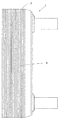
도 1은 종래 기술의 플레이트형 열 교환기의 측면도이다.
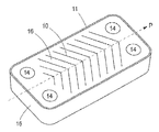
도 2는 도 1에 따르는 플레이트형 열 교환기의 평면도이다.
도 3은 도 1에 따르는 플레이트형 열 교환기의 단면도이다.
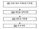
도 4는 본 발명의 방법에 따르는 플레이트형 열 교환기에서 플레이트를 접합하는 방법의 흐름도이다.
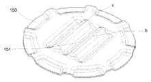
도 5는 2개의 금속 부분를 접합할 수 있는 방법을 설명한 수많은 예에서 사용되는 프레스 가공된 플레이트를 도시한다.
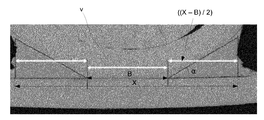
도 6은 도 5에 도시된 플레이트와 평평한 플레이트 사이의 접합부의 단면의 사진이다.
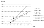
도 7은 추세선을 포함한, 융점 강하 조성물의 도포된 양의 함수로서 접합부 폭이 도시된 다이어그램을 도시한다.
도 8 내지 도 12는 SEM(주사 전자 현미경)에서 조사되는 접합부의 단면 및 전자 주사 위치를 도시한다.1 is a side view of a prior art plate heat exchanger.
2 is a plan view of the plate heat exchanger according to Fig.
3 is a cross-sectional view of the plate heat exchanger according to Fig.
4 is a flow chart of a method of joining a plate in a plate heat exchanger according to the method of the present invention.
Figure 5 shows a press-formed plate used in numerous examples illustrating a method of joining two metal parts.
6 is a photograph of a cross section of the joint between the plate and the flat plate shown in Fig.
Figure 7 shows a diagram illustrating the bond width as a function of the applied amount of the melting point lowering composition, including the trend line.
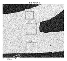
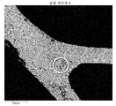
Figs. 8 to 12 show the cross-section and the electron scanning position of the joint portion irradiated by an SEM (scanning electron microscope).
첨부 도면을 참조하여, 플레이트형 열 교환기를 개시하고, 도 1, 도 2 및 도 3을 각각 참조한다. 플레이트형 열 교환기(1)는 제1 매체를 위한 제1 플레이트 사이공간(4) 및 제2 매체를 위한 제2 플레이트 사이공간(5)을 갖는 플레이트 패키지(3)를 형성하도록 서로 옆에 제공되는 복수의 열 교환기 플레이트(2)를 포함한다. 제1 플레이트 사이공간(4) 및 제2 플레이트 사이공간(5)은 플레이트 패키지(3)에서 교대로 제공되고, 즉 매 두 번째 플레이트 사이공간 제1 플레이트 사이공간(4)이고 매 두 번째 플레이트 사이공간이 제2 플레이트 사이공간(5)이며, 도 3을 참조한다.Referring to the accompanying drawings, a plate type heat exchanger is disclosed, and reference is made to Figs. 1, 2 and 3, respectively. The
도 1 내지 3에 개시된 플레이트형 열 교환기(1)는 서로 영구적으로 접합된 열 교환기 플레이트(2)를 갖는다. 2개의 최외측 열 교환기 플레이트가 형성될 수 있고 또는 말단 플레이트에 의해 대체될 수 있다.The plate-
플레이트형 열 교환기(1)는 또한 제1 매체를 제1 플레이트 사이공간(4) 내로 그리고 외부로 운반하고 제2 매체를 제2 플레이트 사이공간(5) 내로 그리고 외부로 운반하도록 배열된, 입구 및 출구 채널(6-9)을 포함한다. 각각의 열 교환기 플레이트(2)는 주 연장 평면(p)으로 연장되고, 열 전달 영역(10) 및 열 전달 영역(10) 둘레로 연장되는 에지 영역(11)을 포함한다. 각각의 열 교환기 플레이트(1)는 열 교환기 플레이트(1)의 제1 말단(1A) 및 열 교환기 플레이트(1)의 제2 말단(1B)에 각각 제공된, 2개의 포트홀(porthole) 영역(12 및 13)을 또한 포함한다. 포트홀 영역(12 및 13)은 에지 영역(11) 내부에, 그리고 보다 구체적으로는 에지 영역(11)과 열 전달 영역(10) 사이에 위치한다. 각각의 포트홀 영역(12, 13)은 각각의 입구 및 출구 채널(6-9)에 맞춰 정렬된 적어도 2개의 포트홀(14)을 포함한다. 각각의 열 교환기 플레이트(1)는 또한 둘러싸고 있는 바깥쪽 플랜지 또는 굴곡 에지(15)를 포함한다. 굴곡 에지 또는 플랜지(15)는 외측에 제공되거나 에지 영역(11)의 바깥쪽 부분을 형성한다. 열 교환기 플레이트(2)은 또한 열 교환기 플레이트(1)의 주연부의 일부분을 따라 연장되는 바깥쪽 굴곡 에지(15)를 가질 수 있다는 점에 주목해야 한다. 따라서 플레이트(2)는 각각 볼록 형상을 갖는 제1 표면(16) 및 오목 형상을 갖는 제2 표면(17)을 갖는다.The plate-
열 전달 영역(10)은 상승부(18) 및 강하부(19)의 파형부를 포함한다. 이러한 강하부 및 상승부는 예를 들어 리지 및 그루브로서 또는 딤플로서 형성될 수 있다.The
플레이트(2)는, 통상적으로 1000℃ 초과의 고상선 온도를 갖기 때문에, 예를 들어 철-, 니켈 및 코발트-계 금속 합금으로 제조될 수 있다. 플레이트는 1000℃ 초과의 고상선 온도를 갖지 않는 순수 구리, 순수 알루미늄 또는 알루미늄-계 합금으로 제조될 수 없다. 예를 들어 플레이트는 통상적으로 철-, 니켈- 및 코발트-계 합금으로 제조될 수 있다.The
플레이트(2)의 금속 또는 심지어 플레이트(2) 자체는 "모재 금속" 또는 "모 재료"로서 지칭될 수 있다. 이러한 맥락에서, "철-기재" 합금은 철이 합금에서 모든 원소 중 가장 많은 중량 퍼센트(wt%)를 갖는 합금이다. 상응하는 상황이 또한 예를 들어 니켈-, 구리-, 코발트-, 크롬- 및 알루미늄-계 합금에도 적용된다.The metal of the
도 4를 참조하여 플레이트형 열 교환기(1)를 위해 플레이트(2)를 접합하는 방법의 흐름도를 설명한다. 플레이트(2)는 전술한 바와 같이 다른 재료로 제조될 수 있다.A flow chart of a method of joining the
제1 단계(201)에서 융점 강하 조성물(20)이 플레이트의 제1 볼록 표면(16)의 적어도 일부분에 도포된다. 융점 강하 조성물(20)은 볼록 표면(16)의 일부분에만 또는 실질적으로 모든 볼록 표면(16)에 도포될 수 있다. 대안적인 실시예에서 융점 강하 조성물(20)은 또한 플레이트(2)의 제2 오목 표면(17)에 도포되지만 또한 제1 볼록 표면(16)에 도포된 융점 강하 조성물의 양보다 적은 양으로 도포될 수 있다.In a first step 201, a melting point lowering composition 20 is applied to at least a portion of the first
도포 자체는 종래의 기법, 예를 들어 융점 강하 조성물이 바인더 성분을 포함하는 경우에는 분무, 스크린 인쇄, 롤링 또는 페인팅에 의해, PVD 또는 CVD에 의해 또는 바인더 성분이 사용되지 않은 경우에는 융점 강하제만을 사용하여 행해질 수 있다.The coating itself can be carried out by conventional techniques, for example by spraying, screen printing, rolling or painting, if the melting point composition contains a binder component, by PVD or CVD, or by using only a melting point depressant when the binder component is not used Lt; / RTI >
융점 강하 조성물(20)은 융점 강하 성분인, 적어도 하나의 성분을 포함한다. 선택적으로, 융점 강하 조성물은 바인더 성분을 포함한다. 적어도 제1 금속 부분의 용융 온도를 낮추는 데 기여하는 융점 강하 조성물의 모든 물질 또는 일부분은 융점 강하 성분의 일부분인 것으로 간주된다. 적어도 제1 금속 부분의 용융 온도를 낮추는 데 관여하지 않고 대신 융점 강하 조성물을 "바인딩"하여, 예를 들어 페이스트, 페인트 또는 슬러리를 형성하는 융점 강하 조성물의 일부분은, 바인더 성분의 일부분인 것으로 간주된다. 물론, 융점 강하 성분은 다른 성분, 예컨대 소량의 필러 금속을 포함할 수 있다. 그러나, 이러한 필러 금속은, 융점 강하 성분의 적어도 25 wt%가 인 및 규소를 포함하기 때문에, 융점 강하 성분의 75 wt% 초과에 상당할 수 없다. 필러 금속이 융점 강하 조성물에 포함된 경우, 이는 항상 융점 강하 성분의 일부분이다.The melting point lowering composition (20) comprises at least one component which is a melting point lowering component. Optionally, the melting point lowering composition comprises a binder component. All materials or portions of the melting point lowering composition that contribute to lowering the melting temperature of at least the first metal portion are considered to be part of the melting point lowering component. A portion of the melting point lowering composition that is not involved in lowering the melting temperature of at least the first metal portion but instead is "bound" to the melting point lowering composition, for example forming a paste, paint or slurry, is considered to be a part of the binder component . Of course, the melting point lowering component may comprise other components, such as a small amount of filler metal. However, such a filler metal can not be more than 75 wt% of the melting point lowering component because at least 25 wt% of the melting point lowering component contains phosphorus and silicon. When the filler metal is included in the melting point lowering composition, it is always part of the melting point lowering component.
이러한 맥락에서, "인 및 규소"는, wt%로 산출된 바와 같은, 융점 강하 성분 중의 인 및 규소의 합계를 의미한다. 여기서, wt%는 질량 분율에 100을 곱함으로써 결정되는 중량 퍼센트를 의미한다. 공지된 바와 같이, 성분 중의 물질의 질량 분율은 성분의 밀도에 대한 그 물질의 질량 농도(성분 중의 그 물질의 밀도)의 비율이다. 따라서, 예를 들어, 적어도 25 wt%의 인 및 규소는 100g인 융점 강하 성분의 샘플 중 인 및 규소의 총 중량이 적어도 25g인 것을 의미한다. 분명히, 바인더 성분이 융점 강하 조성물에 포함된 경우, 융점 강하 조성물 중의 인 및 규소의 wt%는 25 wt% 미만일 수 있다. 그러나, 적어도 25 wt%의 인 및 규소는, 명시된 바와 같이, 포함될 수 있는 임의의 필러 금속을 또한 포함하는 융점 강하 성분에 항상 존재하며, 즉 필러 금속은 항상 융점 강하 조성물의 일부분으로서 여겨진다.In this context, "phosphorus and silicon" means the sum of phosphorus and silicon in the melting point lowering component, as calculated in wt%. Here, wt% means the weight percentage determined by multiplying the mass fraction by 100. As is known, the mass fraction of a substance in an ingredient is the ratio of the mass concentration of that substance to the density of the ingredient (the density of that substance in the ingredient). Thus, for example, at least 25 wt% phosphorus and silicon means that the total weight of phosphorus and silicon in the sample of the melting point lowering component is 100 g, at least 25 g. Obviously, when the binder component is included in the melting point lowering composition, the wt% of phosphorus and silicon in the melting point lowering composition may be less than 25 wt%. However, at least 25 wt% of phosphorus and silicon are always present in the melting point component, which also includes any filler metal that may be included, as indicated, i.e. the filler metal is always regarded as part of the melting point lowering composition.
"인"은 원소 인 뿐만 아니라 인 화합물 내의 인을 포함하는, 융점 강하 성분 중의 모든 인을 포함한다. 상응해서, "규소"는 규소 화합물 중의 규소 뿐만 아니라 원소 규소를 포함하는, 융점 강하 성분 중의 모든 규소를 포함한다. 따라서, 인 및 규소는 둘 다, 융점 강하 성분에서, 다양한 인 및 규소 화합물 중의 인 및 규소에 의해 제시될 수 있다."Phosphorus" includes not only phosphorus but also phosphorus in the melting point lowering component, including phosphorus in the phosphorus compound. Correspondingly, "silicon" includes all silicon in the melting point lowering component, including silicon in the silicon compound as well as elemental silicon. Thus, both phosphorus and silicon can be presented by phosphorus and silicon in various phosphorus and silicon compounds, both in the melting point lowering component.
분명히, 융점 강하 조성물은, 이들이 인 및 규소와 같은 융점 강하 물질에 비해 훨씬 더 많은 충전 금속을 갖기 때문에, 종래의 경납땜 물질과 매우 다르다. 일반적으로, 경납땜 물질은 18 wt% 미만의 인 및 규소를 구비한다.Clearly, melting point lowering compositions are very different from conventional brazing materials, because they have much more fill metal than melting point lowering materials such as phosphorus and silicon. Generally, the braze material comprises less than 18 wt% phosphorus and silicon.
상기 방법은 필러 금속을 저감시키거나 심지어 배제할 수 있고 이를 다른 재료로 제조된 금속 부분을 위해 적용할 수 있다는 점에서 유리하다. 또한, 광범위한 용도 내에서, 예를 들어 그렇지 않으면 예를 들어, 용접 또는 종래의 경납땜에 의해 접합되는 열 전달 플레이트 또는 임의의 적합한 금속 물체를 접합시키는 데 사용할 수 있다.The method is advantageous in that the filler metal can be reduced or even eliminated and this can be applied to metal parts made of other materials. It can also be used in a wide range of applications, for example, to bond heat transfer plates or any suitable metallic object that otherwise would be bonded by, for example, welding or conventional brazing.
본 발명의 또 다른 실시예에서 융점 강하 조성물(20)은 후속적으로 플레이트(2)로 절단되는 코일에 도포된다.In another embodiment of the present invention, the melting point lowering composition 20 is applied to a coil which is subsequently cut into a
이후의 단계(202)에서 제2 플레이트(22)의 제2 오목 표면(17)을 제1 플레이트(21)의 제1 볼록 표면(16) 상의 접촉점(23)에서 융점 강하 조성물(20)과 접촉시킨다. 제1 및 제2 플레이트를 적층시킴으로써 플레이트 패키지(3)가 생성된다. 이는 종래의, 자동화 제조 시스템을 이용함으로써 수동으로 또는 자동으로 실시될 수 있다. 물론, 융점 강하 조성물(20)은 제2 플레이트(22)의 제2 오목 표면(17)에 도포될 수 있다.In a subsequent step 202 the second
인은 원소 인, 및 다음의 화합물: 인화 망간, 인화철, 및 인화 니켈 중 적어도 임의의 것으로부터 선택된 인 화합물의 인 중 임의의 것으로부터 유래될 수 있다. 규소는 원소 규소, 및 다음의 화합물: 탄화 규소, 붕화 규소 및 규소철 중 적어도 임의의 것으로부터 선택된 규소 화합물의 규소 중 임의의 것으로부터 유래될 수 있다.Phosphorus can be derived from any of phosphorus, which is an element, and a phosphorus compound selected from at least any of the following compounds: manganese phosphide, iron phosphide, and nickel phosphide. Silicon can be derived from any of the elements silicon, and silicon of a silicon compound selected from at least any of the following compounds: silicon carbide, silicon boride and silicon iron.
융점 강하 성분은 적어도 25 wt%, 적어도 35 wt%, 및 적어도 55 wt%의 인 및 규소를 포함할 수 있다. 이는 임의의 필러 금속이 존재하는 경우 75 wt% 미만, 65 wt% 미만, 45 wt%의 양으로 각각 존재하는 것을 의미한다.The melting point lowering component may comprise at least 25 wt%, at least 35 wt%, and at least 55 wt% phosphorus and silicon. This means that if any filler metal is present, it is present in amounts of less than 75 wt%, less than 65 wt%, and 45 wt%, respectively.
인은 융점 강하 화합물의 인 및 규소 함량의 적어도 10 wt%를 구성할 수 있다. 이는 융점 강하 성분이 적어도 25 wt%의 인 및 규소를 포함하는 경우, 융점 강하 성분이 적어도 2.5 wt%의 인를 포함하는 것을 의미한다. 규소는 융점 강하 화합물의 인 및 규소 함량의 적어도 55 wt%를 구성할 수 있다.Phosphorus may constitute at least 10 wt% of the phosphorus and silicon content of the melting point lowering compound. This means that when the melting point lowering component comprises at least 25 wt% phosphorus and silicon, the melting point lowering component comprises at least 2.5 wt% phosphorus. The silicon may constitute at least 55 wt% of the phosphorus and silicon content of the melting point lowering compound.
융점 강하 성분은 50 wt% 미만의 금속 원소, 또는 10 wt% 미만의 금속 원소를 포함할 수 있다. 이러한 금속 원소는 상술된 "금속 필러"에 해당한다. 이러한 소량의 금속 원소 또는 금속 필러는 융점 강하 조성물(20)을 예를 들어 공지된 경납땜 조성물과 구별하는데, 경납땜 조성물은 적어도 60 wt%의 금속 원소를 포함하기 때문이다. 여기서, "금속 원소"는 예를 들어, 주기율표 상의 3 내지 12족을 포함하는, 주기율표의 d-블록에 있는 원소인, 모든 전이 금속을 포함한다. 이는, 예를 들어, 철(Fe), 니켈(Ni), 코발트(Co), 크롬(Cr) 및 몰리브덴(Mo)이 "금속 원소"임을 의미한다. "금속 원소"가 아닌 원소는 영족 기체, 할로겐 및 다음의 원소, 붕소(B), 탄소(C), 규소(Si), 질소(N), 인(P), 비소(As), 산소(O), 황(S), 셀레늄(Se) 및 텔루륨(Tu)이다. 예를 들어, 인이 화합물 인화 망간에서 비롯된 경우, 이 화합물의 망간-부분은 일 실시예에서는 50 wt% 미만이어야 하고 다른 실시예에서는 10 wt% 미만이어야 하는 금속 원소에 포함된 금속 원소인 점에 주목해야 한다.The melting point lowering component may contain less than 50 wt% of the metal element, or less than 10 wt% of the metal element. Such a metal element corresponds to the above-mentioned "metal filler". These small amounts of metallic elements or metal fillers differentiate the melting point lowering composition 20 from, for example, known brazing compositions, since the brazing composition contains at least 60 wt% of the metallic element. Here, "metal element" includes, for example, all transition metals, which are elements in the d-block of the periodic table, including
플레이트(2)는 0.3 - 0.6㎜의 두께를 포함할 수 있고 그때 융점 강하 조성물(R)의 도포 단계(201)는 제1 플레이트(21)의 제1 볼록 표면(16) 상에 ㎟ 당 평균 0.02 - 1.00㎎의 인 및 규소를 도포하는 것을 포함한다. 제1 볼록 표면(16)의 표면 상에 ㎟ 당 평균 0.02 - 1.00㎎의 인 및 규소의 도포는 예를 들어 제2 오목 표면(17)을 통한, 예를 들어 제2 플레이트(22)로부터 제1 플레이트(21)로 전달되는 인 및 규소의 임의의 간접적인 도포를 포함한다. 따라서, 여기에서 지칭되는 인 및 규소는 제1 플레이트(21)의 제1 볼록 표면(16)의 표면층의 용융에 계속해서 기여하는 한, 반드시 제1 플레이트(21)에 직접 도포되었어야 하는 것은 아니다.The
플레이트(2)는 0.6 - 1.0㎜의 두께를 가질 수 있고 그 때 융점 강하 조성물(20)의 도포는 플레이트(2)의 표면 상에 ㎟ 당 평균 0.02 - 1.0㎎의 인 및 규소의 도포를 포함할 수 있다.The
플레이트(2)는 1.0㎜ 초과의 두께를 가질 수 있고 그 때 융점 강하 조성물의 도포는 플레이트(2)의 표면 상에 ㎟ 당 평균 0.02 - 5.0㎎의 인 및 규소의 도포를 포함할 수 있다.The
융점 강하 조성물은 접촉점(23)에 의해 한정된 영역보다 넓은 면적을 갖는 표면에 도포될 수 있어, 접합부가 형성되도록 허용할 때 용융된 금속층 중의 금속이 접촉점으로 흐르게 된다. 이러한 흐름은 통상적으로 모세관 작용에 기인한다.The melting point lowering composition can be applied to a surface having a larger area than the area defined by the contact points 23 so that the metal in the molten metal layer flows to the contact point when allowing the junction to be formed. This flow is typically due to capillary action.
용융 성분 표면의 영역은 접촉점(23)에 의해 규정된 영역보다 적어도 3배 넓을 수 있다. 표면의 영역은 훨씬 더 넓을 수 있고(또는 접촉점이 비교적 더 적을 수 있음), 예컨대 접촉점에 의해 규정된 영역보다 적어도 10배, 20배 또는 30배 더 넓을 수 있다. 표면의 영역은 용융된 금속이 이로부터 흘러 접합부를 형성하는 표면의 영역으로 지칭된다. 물론 융점 강하 조성물이 제1 플레이트(21)의 모든 제1 볼록 표면(16)에 도포될 수 있다.The area of the surface of the molten component may be at least three times wider than the area defined by the
표면의 영역은 접합부의 단면적보다 적어도 3배 또는 적어도 10배 클 수 있다. 표면의 영역은 훨씬 더 클 수 있고(또는 접합부의 단면적이 비교적 더 작을 수 있음), 예컨대 접촉점에 의해 한정된 영역보다 적어도 6배 또는 10배 더 넓다. 접합부의 단면적은 접합부가 그의 가장 작은 연장부(단면적)를 갖는 위치에서, 접촉점이 위치한 표면에 평행한 평면을 가로질러 접합부가 갖는 단면적으로 정의할 수 있다.The area of the surface can be at least three times or at least ten times greater than the cross-sectional area of the joint. The area of the surface can be much larger (or the cross-sectional area of the joints can be relatively small), e.g., at least six or ten times wider than the area defined by the contact points. The cross-sectional area of the joint can be defined as the cross-sectional area of the joint across the plane parallel to the surface on which the contact point is located, at the location where the joint has its smallest extension (cross-sectional area).
제1 플레이트(2)는The first plate (2)
i) >50 wt% Fe, <13 wt% Cr, <1 wt% Mo, <1 wt% Ni 및 <3 wt% Mn,i)> 50 wt% Fe, <13 wt% Cr, <1 wt% Mo, <1 wt% Ni and <3 wt%
ii) >90 wt% Fe,ii) > 90 wt% Fe,
iii) >65 wt% Fe 및 >13 wt% Cr,iii) > 65 wt% Fe and > 13 wt% Cr,
iv) >50 wt% Fe, >15.5 wt% Cr 및 >6 wt% Ni,iv) > 50 wt% Fe, > 15.5 wt% Cr and > 6 wt% Ni,
v) >50 wt% Fe, >15.5 wt% Cr, 1-10 wt% Mo 및 >8 wt% Ni,v) > 50 wt% Fe, > 15.5 wt% Cr, 1-10 wt% Mo and > 8 wt% Ni,
vi) >97 wt% Ni, vi) > 97 wt% Ni,
vii) >10 wt% Cr 및 >60 wt% Ni,vii) > 10 wt% Cr and > 60 wt% Ni,
viii) >15 wt% Cr, >10 wt% Mo 및 >50 wt% Ni, viii) > 15 wt% Cr, > 10 wt% Mo and > 50 wt% Ni,
ix) >70 wt% Co, 및ix) > 70 wt% Co, and
x) >10 wt% Fe, 0.1-30 wt% Mo, 0.1-30 wt% Ni 및 >50 wt% Co,x) > 10 wt% Fe, 0.1-30 wt% Mo, 0.1-30 wt% Ni and > 50 wt% Co,
중 임의의 것을 포함할 수 있다.And the like.
상기는 플레이트(2)가 다수의 상이한 합금으로 제조될 수 있음을 의미한다. 분명히, 상기 예는, 산업계 내에서 통상적인 바와 같이, 다른 금속 또는 원소와 균형을 이룬다.This means that the
다음 단계(203)에서, 플레이트 패키지(3)는 1000℃ 초과의 온도로 가열된다. 정확한 온도는 이하의 실시예에서 알 수 있다. 가열 동안 제1 플레이트(21)의 제1 볼록 표면(16)이 용융되어 표면층(24)을 형성하고, 융점 강하 성분과 함께, 제1 플레이트(21)와 제2 플레이트(22) 사이의 접촉점(23)에서 제2 플레이트(22)의 제2 오목 표면(17)과 접촉하는 용융된 금속층(25)을 형성한다. 이것이 일어날 때, 용융된 금속층의 금속은 접촉점(23)을 향해 흐른다.In the next step 203, the
마지막 단계(204)에서, 용융된 금속층(25)은 응고하게 되어, 플레이트 패키지(3)의 플레이트들 사이의 접촉점(23)에서 접합부(26)가 획득되고 플레이트 패키지(3)의 플레이트(2)의 굴곡 에지(15) 사이에서 굴곡 에지(15)가 밀착 체결부를 형성하는데, 즉 접촉점(23)으로 흘렀던 금속이 응고된다. 융점 강하 조성물(20)을 플레이트(2)의 볼록 표면(16)에만 도포하는 도포 단계(201)에 의해, 놀랍게도 플레이트(2)의 형상 변화가 발생하여 플레이트(2)의 볼록 형상이 훨씬 더 볼록하게 되는데, 즉 굴곡 에지(15)가 플레이트 패키지(3)에서 서로에게 매우 밀착하게 꼭 맞는 체결부를 생성하여, 공지된 경납땜 기법에서보다 더 밀착하게 되는 것이 발견되었다. 실제로, 본래 거리보다 굴곡 에지(15) 사이에서 또한 더욱 밀착됐다. 비교해보면, 오목 표면(17)에만 융점 강하 조성물(20)을 도포한 경우, 굴곡 에지(15) 사이의 틈이 증가한다. 블렌드가 표면과 합금되는 경우 형상의 변화가 일어나는데, 또한 합금으로 인해 표면에서 압축 응력이 있을 수 있는 것을 의미한다. 양쪽 융점 강하 조성물이 볼록 표면(16) 및 오목 표면(17) 둘 다에 도포된 경우 양 표면에 존재하는 압축 응력이 있을 수 있고, 플레이트(2) 및 플레이트 패키지(3)의 피로 강도의 증가를 초래한다.In a final step 204 the molten metal layer 25 solidifies so that at the point of
응고는 통상적으로 온도를 보통 실온으로 낮추는 것을 포함한다. 그러나, 온도를 낮추기 전, 접합부 영역에서의 성분(인 및 규소)의 재분배의 물리적 과정 동안 응고가 또한 일어난다.Clotting typically involves lowering the temperature to normal room temperature. However, prior to lowering the temperature, coagulation also occurs during the physical process of redistribution of the components (phosphorus and silicon) in the bond region.
접합될 금속 부분의 형상에 따라서, 융점 강하 조성물이 도포된 영역은 후속하여 형성되는 접합부의 영역과 실질적으로 동일할 수 있다.Depending on the shape of the metal part to be bonded, the area to which the melting point lowering composition is applied may be substantially the same as the area of the subsequently formed bond.
상기 기재로부터, 본 발명의 다양한 실시예가 설명되고 도시되었으나, 본 발명은 이에 제한되지 않으며, 본 발명은 하기 청구범위에서 한정된 청구 사항의 범위 내에서 다른 방식으로 구현될 수도 있다. 다양한 융점 강하 조성물은 또한 금속 부분을 위해 다양한 금속과 조합될 수 있다. 예를 들어, 융점 강하 조성물(블렌드)(A3.3)은 316 강으로 제조된 금속 부분과 조합될 수 있다.While various embodiments of the invention have been illustrated and described, it will be understood that the invention is not limited thereto and that the invention may be otherwise embodied within the scope of the appended claims. Various melting point descending compositions can also be combined with various metals for the metal part. For example, a melting point lowering composition (A3.3) may be combined with a metal part made of 316 steel.
예Yes
플레이트에 적합한 재료, 융점 강하 조성물(23)의 조성, 어느 정도의 양의 융점 강하 조성물이 사용되어야 하는지, 가열하기 적합한 온도, 얼마나 오랫동안 가열을 수행할 것인지 등에 대해 설명하기 위해 이제 다수의 실험 및 실시예를 제시한다. 따라서, 이들 실험 및 예의 결과는 제1 플레이트, 제2 플레이트, 융점 강하 조성물, 접촉점, 접합부 등과 같은 상술된 실체에 대해 이용되고, 즉 모든 상술된 실체는 이하의 실험 및 예와 관련하여 기재된 각각 관련된 특징부를 포함시킬 수 있다. 이하에서 융점 강하 조성물은 "블렌드"로서 지칭된다. 금속 플레이트는 "모재 금속"으로 지칭될 수 있다.A number of experiments and studies are now being conducted to illustrate the suitable material for the plate, the composition of the melting point lowering composition (23), how much positive melting point composition should be used, the temperature suitable for heating, how long heating will be performed, Give an example. Thus, the results of these experiments and examples are used for the above described entities such as the first plate, the second plate, the melting point lowering composition, the contact points, the junctions, etc., that is, all the above- Features can be included. Hereinafter the melting point lowering composition is referred to as a "blend ". The metal plate may be referred to as "base metal ".
다수의 적합한 융점 강하 조성물, 즉 융점 온도 강하 조성물이 실험되었다. 융점 강하 조성물의 활성 성분은 인(P)이다. 인의 화합물이 인을 위한 공급원으로서 선택되었다. 화합물은 Fe3P, NiP 및 Mn3P2를 포함하고, Mn3P2는 MnP 및 Mn2P의 혼합물이다. 인을 포함하는 다른 화합물이 또한 사용될 수 있으며, 다른 화합물은 이들의 유용성 관련하여 그리고 이들이 제공하는 결과와 관련하여 Fe3P, NiP 및 Mn3P2에 대해 행해지는 바와 같이 그리고 이후 설명되는 바와 유사한 방식으로 검증되어야 한다.A number of suitable melting point lowering compositions, i.e., melting point temperature lowering compositions, have been tested. The active ingredient of the melting point lowering composition is phosphorus (P). The phosphorus compound was selected as the source for phosphorus. The compound includes Fe 3 P, NiP and Mn 3 P 2 , and Mn 3 P 2 is a mixture of MnP and Mn 2 P. Other compounds including phosphorus may also be used and other compounds may be used as well as their usefulness and in relation to the results they provide, as is done for Fe 3 P, NiP and Mn 3 P 2 , .
인화철로도 지칭되는 Fe3P는 12023-53-9의 CAS(Chemical Abstracts Service) 번호 및 MFCD00799762의 MDL(Molecular Design Limited) 번호로서 Alfa Aesar 회사로부터 획득되는 종래 화합물이다.Fe 3 P, also referred to as iron oxide, is a conventional compound obtained from the Alfa Aesar company as a Chemical Abstracts Service (CAS) number of 12023-53-9 and a MDL (Molecular Design Limited) number of MFCD00799762.
인화망간으로도 지칭되는 Mn3P2는, 12263-33-1의 CAS(Chemical Abstracts Service) 번호 및 MFCD00064736의 MDL(Molecular Design Limited) 번호로서 Alfa Aesar 회사로부터 획득되는 종래 화합물이다.Mn 3 P 2 , also referred to as manganese phosphide, is a conventional compound obtained from the Alfa Aesar company as the Chemical Abstracts Service (CAS) number of 12263-33-1 and the MDL (Molecular Design Limited) number of MFCD00064736.
니켈 인으로도 지칭되는 NiP는 접합될 금속 부분 상에 도금된 종래 화합물이다. 접합될 금속 부분은 또한 모재 금속 또는 모재 재료로 지칭된다. 도금은 예를 들어, 스웨덴 노르코핑에 소재된 Brink Fornicklingsfabriken AB 회사에 의해 행해지는 바와 같이, 종래의 니켈 인 도금법을 수행함으로써 해해진다.NiP, also referred to as nickel phosphorus, is a conventional compound plated on the metal part to be bonded. The metal part to be bonded is also referred to as the base metal or base metal. Plating is solved, for example, by performing a conventional nickel plating process, as is done by Brink Fornicklingsfabriken AB company in Norrkoping, Sweden.
몇몇 예에 대해, Si 또는 규소가 사용되었다. 규소는 CAS 7440-21-3 및 MDL MFCD00085311로서 Alfa Aesar 회사로부터 획득되는 종래 화합물이고, "규소 분말, 결정질, -325 메쉬, 99.5%(금속 기반)"로 지칭된다.For some examples, Si or silicon has been used. Silicon is a conventional compound obtained from Alfa Aesar company as CAS 7440-21-3 and MDL MFCD00085311 and is referred to as "silicon powder, crystalline, -325 mesh, 99.5% (metal based)".
원자 중량을 적용함으로써 그리고 종래의 계산 기법에 의해 화합물의 원자 조성물을 살펴볼 때, Fe3P는 16 wt%의 P(인)을 포함하고 Mn3P2 은 27 wt%의 P을 포함하는 것으로 판정될 수 있다.Looking at the atomic composition of the compound by applying atomic weights and by conventional calculation techniques, it is concluded that Fe 3 P contains 16 wt% P (phosphorus) and Mn 3 P 2 contains 27 wt% P .
니켈 도금시, 대략 11-14 wt%의 P가 NiP 층에 포함된다.Upon nickel plating, about 11-14 wt% of P is included in the NiP layer.
바인더는 접합될 금속 부분 상에 Fe3P 및 Mn3P2을 도포하기 위해 사용된다. 바인더(중합체 및 용매)는 Wall Colmonoy 회사에 의해 Nicorobraz S-20(S-20)의 명칭으로 판매되는 바인더이다. 바인더의 샘플이 금속 플레이트 상에 배치되고 22 ℃ 에서 24시간 동안 건조된다. 샘플의 중량은 건조 이전에 0.56 g이고 건조 이후 0.02 g 이었다. 따라서, 바인더의 3.57 wt%가 건조 이후 잔류하는 성분이다. 융점 강하 조성물은 Mn3P2 및 Si가 융점 강하 성분(융점 온도 강하 성분)을 형성하는 곳 그리고 바인더 S-20가 바인더 성분을 형성하는 곳에서 준비된다. 이 준비는 먼저 Mn3P2와 Si를 혼합한 이후 바인더 S-20를 추가 및 혼합함으로써 행해진다. 상이한 양의 Si을 갖는 융점 강하 조성물의 두 개의 변수가 준비되고, 표 1에 도시된 바와 같이, A1 Mn3P2(A1) 및 B1 Mn3P2(B1)로 지칭된다.The binder is used to apply Fe 3 P and Mn 3 P 2 on the metal part to be bonded. The binder (polymer and solvent) is a binder sold under the name Nicorobraz S-20 (S-20) by the Wall Colmonoy company. A sample of the binder is placed on a metal plate and dried at 22 DEG C for 24 hours. The weight of the sample was 0.56 g before drying and 0.02 g after drying. Thus, 3.57 wt% of the binder is the remaining component after drying. The melting point lowering composition is prepared where Mn 3 P 2 and Si form a melting point lowering component (melting point temperature lowering component) and where the binder S-20 forms a binder component. This preparation is carried out by first mixing Mn 3 P 2 and Si and then adding and mixing the binder S-20. The two variables of the melting point lowering compositions having different amount of Si is prepared, as shown in Table 1, it referred to as A1 Mn 3 P 2 (A1) and B1 Mn 3 P 2 (B1) .

도 5에서, 조성물(A1 및 A2)은 스테인리스 강 유형 316L(SAE 강 등급)의 편평하고 42mm 직경을 갖는 원형 실험 피스 상에 도포된다.In Fig. 5, compositions A1 and A2 are applied on a flat, 42 mm diameter circular test piece of stainless steel type 316L (SAE steel grade).
매 실험 피스에 대해, 상이한 재료의 다른 피스, 254 SMO(SAE 강 등급)가 배치된다. 이 다른 피스가 도 5에 도시되며, 42mm의 직경 및 0.4mm의 두께의 원형 프레스 가공된 플레이트(150)의 형태를 갖는다. 프레스 가공된 플레이트(150)는 두 개의 프레스 가공된 비임(v, h)을 갖고, 이들 각각의 길이는 대략 20mm이다. 비임을 구비한 피스가 편평한 피스 상에 배치될 때, 피스(150)의 비임이 다른 편평한 피스와 맞닿는 곳에 접촉점이 형성된다.For each experimental piece, another piece of different material, 254 SMO (SAE grade) is placed. This other piece is shown in FIG. 5 and has the form of a circular press-machined
피스, 즉, 편평한 원형 피스 및 프레스 가공된 플레이트는 샘플로 지칭되고, 여러 샘플들이 샘플 각각에 대해 상이한 온도에서 2시간 동안 진공에서 열 처리된다. 표 2는 샘플에 대해 사용된 조성물의 양을 도시한다.The piece, that is, the flat circular piece and the pressed plate are referred to as samples, and several samples are heat treated in a vacuum for two hours at different temperatures for each sample. Table 2 shows the amount of composition used for the sample.
샘플(A1:1 내지 A1:3) 및 샘플(B1:1 내지 B1:3)에 대해, 열 처리는 진공에서 2시간 동안 1120℃의 온도에서 샘플을 유지하는 것을 포함한다.For the samples A1: 1 to A1: 3 and the samples B1: 1 to B1: 3, the heat treatment involves holding the sample at a temperature of 1120 deg. C for 2 hours under vacuum.
샘플(A1:4 내지 A1:6) 및 샘플(B1:4 내지 B1:6)에 대해, 열 처리는 진공에서 2시간 동안 1140℃의 온도에서 샘플을 유지하는 것을 포함한다.For samples A1: 4 to A1: 6 and samples B1: 4 to B1: 6, the heat treatment involves holding the sample at a temperature of 1140 DEG C for 2 hours in vacuum.
A1은 조성물(A1 Mn3P2)을 나타내고, B2는 조성물(B1 Mn3P2)을 나타낸다. 각각 A1과 B2 이후의 숫자는 표 2에 제시된 바와 같이 상이한 샘플을 나타낸다. 이 표에, 건식 바인더 성분의 중량 및 융점 강하 성분의 중량을 포함하는 샘플의 중량이 제시된다.A1 denotes a composition (A1 Mn 3 P 2), B2 represents a composition (B1 Mn 3 P 2). The numbers after A1 and B2, respectively, represent different samples as shown in Table 2. In this table, the weight of the sample including the weight of the dry binder component and the weight of the melting point lowering component is presented.

열 처리 이후 샘플은 실온(22℃)까지 냉각되고 샘플의 두 개의 피스가 프레스 가공된 플레이트(150)의 비임의 길이를 따라서 접합되고, 즉, 샘플은 비임을 따라서 접합부를 갖는다. 샘플은 두 개의 섹션에서 접합부를 가로질러 절단되고 각각의 접합부는 도 6에 도시된 가장 넓은 섹션(X)에서 계측된다. 결과가 표 3에 제시되고 도 7의 도면에 도시되며, 접합부의 폭은 융점 강하 조성물의 도포량의 함수로서 도해된다.After the heat treatment, the sample is cooled to room temperature (22 DEG C) and two pieces of the sample are bonded along the length of the beam of the pressed

이후 야금 조사가 접합부에 대해 행해진다. 이는 X-선 검출기를 갖는 종래의 상업적으로 이용 가능한 주사 전자 현미경인, 소위 SEM-EDX에서 접합부의 절단면을 분석함으로써 행해진다. 도 8은 샘플 A1-6에 대한 3 측정 위치를 도시하고 표 4는 측정 결과를 나타낸다.Metallurgical investigation is then carried out on the joint. This is done by analyzing the section of the junction in a so-called SEM-EDX, which is a conventional commercially available scanning electron microscope with an X-ray detector. FIG. 8 shows three measurement positions for Sample A1-6 and Table 4 shows the measurement results.

조사는 접합부가 가열 이전에 제1 금속 부분 및 제2 금속 부분 중 임의의 것의 일부인 금속, 즉 샘플의 피스를 적어도 90 wt%를 포함하는 것을 나타낸다. 이는 Mn 및 P가 함께 2.2 wt% 미만을 나타내기 때문에 쉽게 결정된다.The irradiation indicates that the joint contains at least 90 wt% of a piece of metal, i.e., a sample, that is part of any of the first metal portion and the second metal portion prior to heating. This is easily determined because Mn and P together represent less than 2.2 wt%.
유사한 조사가 또한 샘플 B1-6에 대해 행해진다. 도 9는 샘플 B1-6에 대한 3 측정 위치를 도시하고 표 5는 측정 결과를 나타낸다.A similar investigation is also made for sample B1-6. Figure 9 shows three measurement locations for sample B1-6 and Table 5 shows the measurement results.

조사는 접합부가 가열 이전에, 제1 금속 부분 및 제2 금속 부분 중 임의의 부인 금속, 즉 샘플의 피스를 적어도 90 wt%를 포함하는 것을 나타낸다. 이는 Mn 및 P가 함께 4.2 wt% 미만을 나타내기 때문에 쉽게 결정된다The irradiation indicates that the joint comprises at least 90 wt% of any of the first metal portion and the second metal portion, i.e., a piece of the sample, prior to heating. This is easily determined because Mn and P together represent less than 4.2 wt%
316로서 지칭되며, 42mm의 직경을 갖는 316 유형의 스테인리스 강의 다음 실험 피스에서, 3개의 상이한 융점 강하 조성물(각자의 피스 상에 하나의 조성물): i) Mn3P2, ii) 316 상에 도금된 NiP, 및 iii) 융점 강하제로서 Si와 함께 316 상에 도금된 NiP이 도포된다. 도금된 NiP의 두께는 50㎛이다. 0.15g Si가 종래의 페인팅에 의해 도포된다. 모든 피스에 대해, 유형 254 SMO의 도 5와 유사한 프레스 가공된 피스가 배치된다. 피스는 1120℃에서 진공에서 2시간 동안 열 처리된 샘플을 형성한다. 접합부는 피스들 사이에 형성되었다.(One composition on each piece): i) Mn 3 P 2 , ii) 316 on a 316 type stainless steel with a diameter of 42 mm, And iii) plated NiP on 316 with Si as a melting point depressant. The thickness of the plated NiP is 50 탆. 0.15 g Si is applied by conventional painting. For all the pieces, a press-processed piece similar to that of Fig. 5 of type 254 SMO is placed. The piece forms a heat treated sample at < RTI ID = 0.0 > 1120 C < / RTI > in a vacuum for 2 hours. The joint was formed between the pieces.
표 6은 50㎛ NiP 도금을 갖는 샘플에 대해 SEM-EDX를 사용하여 접합부의 절단면의 분석을 나타낸다. 결과로부터, 접합부는 가열 이전에 피스(제1 금속 부분) 또는 두번째 피스(제2 금속 부분) 중 임의의 부분인 금속을 적어도 20 wt%를 포함하는 것으로 보인다. 도 10은 접합부 내의 측정 위치를 도시한다.≪ tb > TABLE 6 < tb > < tb > < SEP > SEM-EDX < SEP > As a result, the joint appears to contain at least 20 wt% of metal, which is any portion of the piece (first metal portion) or the second piece (second metal portion) prior to heating. Figure 10 shows the measurement position in the joint.

표 7은 Si의 app 0.15g 양이 도금된 표면에 도포(페인팅)된 50 ㎛ NiP 도금을 갖는 샘플에 대해 SEM-EDX를 사용한 접합부의 절단면의 분석을 도시한다. 결과로부터, 접합부는 Si가 사용되지 않은 실험에 비해 더 많은 금속을 포함하는 것으로 보인다. 더 많은 양의 Si는 실험 피스로부터 비롯된 접합부 내의 금속의 양을 증가시킬 수 있다. 도 11은 접합부 내의 측정 위치를 도시한다.Table 7 shows an analysis of the section of the joint using SEM-EDX for a sample with a 50 탆 NiP plating applied to the plated surface in an amount of 0.15 g of the app of Si. From the results, the joint appears to contain more metal than the experiment where Si is not used. Larger amounts of Si can increase the amount of metal in the joints resulting from the test pieces. 11 shows the measurement position in the joint.

표 8은 Mn3P2를 갖는 샘플에 대해 SEM-EDX를 사용하여 접합부의 절단면의 분석을 도시한다. Mn3P2는 S-20 바인더로 50 wt: 50 wt를 혼합되지만, Si는 사용되지 않는다. 0.2g의 양(바인더 성분의 건조 이후)이 도포되었다. 결과로부터, 접합부는 접합 이전에, 접합된 제품의 일부인 금속을 적어도 80 wt%를 포함하는 것으로 보인다. 도 12는 접합부 내의 스펙트럼 1 측정의 위치를 도시한다.Table 8 shows an analysis of the section of the junction using SEM-EDX for samples with Mn 3 P 2 . Mn 3 P 2 is mixed with 50 wt: 50 wt of S-20 binder, but Si is not used. An amount of 0.2 g (after drying of the binder component) was applied. From the results, the joint appears to contain at least 80 wt% of the metal that is part of the bonded product prior to bonding. Figure 12 shows the location of the spectral 1 measurement in the junction.

Claims (22)
각각의 열 교환기 플레이트(2)는 열 전달 영역(10), 및 열 전달 영역(10) 둘레로 연장되는 굴곡 에지(15)를 구비하는 에지 영역(11)을 포함하고,
플레이트(2)의 제1 표면(16)은 볼록 형상을 형성하고, 플레이트의 제2 표면(17)은 오목 형상을 형성하고,
열 전달 영역(10)은 상승부(18) 및 강하부(19)의 파형부를 포함하고,
플레이트의 상기 파형부 및 굴곡 에지(15)는 플레이트(2)를 프레스 가공함으로써 제공되고,
상기 방법은
제1 플레이트(21)의 제1 볼록 표면(16)의 적어도 일부 상에 융점 강하 조성물(20)을 도포하는 도포 단계(201)로서, 융점 강하 조성물(20)은
ㆍ 제1 플레이트(21)의 용융 온도를 낮추기 위해 인 및 규소를 포함하는 융점 강하 성분, 및
ㆍ 선택적으로, 제1 볼록 표면(16) 상에 융점 강하 조성물(20)을 도포하는 단계(201)를 용이하게 하기 위한 바인더 성분을 포함하는, 도포 단계,
플레이트(21, 22)를 플레이트 패키지(3)로 적층시킴으로써 제2 플레이트(22)의 제2 오목 표면(17)을 제1 플레이트(21)의 상기 제1 볼록 표면(16) 상의 융점 강하 조성물(20)과 접촉시키는 접촉 단계(202),
제1 및 제2 플레이트(21, 22)를 1000℃ 초과의 온도로 가열하는 가열 단계(203)로서, 제1 플레이트(21)의 상기 제1 볼록 표면(16)이 이에 의해 용융되어, 제1 플레이트(21)의 표면층(24)이 용융되고 융점 강하 성분(20)과 함께 용융된 금속층(25)을 형성하며 용융된 금속층은 제1 플레이트(21)와 제2 플레이트(22) 사이의 접촉점(23)에서 제2 플레이트(22)와 접촉하게 되는, 가열 단계, 및
굴곡 에지(15)가 플레이트 패키지(3) 내의 플레이트(2)의 굴곡 에지(15)들 사이에 밀접 체결부를 형성하도록, 용융된 금속층(25)을 응고시키고 플레이트 패키지(3) 내의 플레이트(2)들 사이의 접촉점(23)에 접합부(26)를 형성하는 단계로서, 접합부(26)는 가열 단계(203) 이전에 제1 플레이트(21) 및 제2 플레이트(22) 중 임의의 것의 부분인 금속을 적어도 50 wt%를 포함하는, 단계를 포함하는, 플레이트형 열 교환기의 제조 방법.A method of manufacturing a permanently bonded plate heat exchanger (1) comprising a plurality of metal heat exchanger plates (2) having solidus temperatures above 1000 DEG C, wherein a plurality of metal heat exchanger plates (3) having a first plate-to-plate space (4) for a first medium and a second plate-to-plate space (5) for a second medium, 5 are alternately provided in the plate package 3,
Each heat exchanger plate 2 includes a heat transfer zone 10 and an edge zone 11 having a bending edge 15 extending around the heat transfer zone 10,
The first surface 16 of the plate 2 forms a convex shape and the second surface 17 of the plate forms a concave shape,
The heat transfer area 10 includes a raised portion 18 and a corrugated portion of the lower portion 19,
The corrugated portion of the plate and the curved edge 15 are provided by pressing the plate 2,
The method
The application of the melting point lowering composition 20 onto at least a part of the first convex surface 16 of the first plate 21,
A melting point lowering component containing phosphorus and silicon to lower the melting temperature of the first plate 21, and
Optionally, a binder component for facilitating step (201) of applying the melting point lowering composition (20) on the first convex surface (16)
By stacking the plates 21 and 22 with the plate package 3 the second concave surface 17 of the second plate 22 is brought into contact with the melting point lowering composition on the first convex surface 16 of the first plate 21 A contact step 202 for contacting the substrate 20,
As a heating step 203 for heating the first and second plates 21 and 22 to a temperature above 1000 ° C, the first convex surface 16 of the first plate 21 is melted thereby, The surface layer 24 of the plate 21 melts and forms a molten metal layer 25 together with the melting point lowering component 20 and the melted metal layer is contacted with the contact point between the first plate 21 and the second plate 22 23 in contact with the second plate 22, and
The molten metal layer 25 is solidified and the plate 2 in the plate package 3 is heated so that the curved edge 15 forms a tight junction between the curved edges 15 of the plate 2 in the plate package 3. [ Forming a joint 26 at a point of contact 23 between the first plate 21 and the second plate 22 such that the bond 26 is in contact with a portion of any of the first plate 21 and the second plate 22 prior to the heating step 203, Of at least 50 wt%. ≪ RTI ID = 0.0 > 11. < / RTI >
인은 인 화합물로부터 유래되고, 상기 인 화합물은 MnxPy, FexPy 및 NixPy 중 적어도 임의의 것으로부터 선택되는, 플레이트형 열 교환기의 제조 방법.The method according to claim 1,
Phosphorus is derived from a phosphorus compound and the phosphorus compound is selected from at least any of Mn x P y , Fe x P y and Ni x P y .
규소는 원소 규소, 및 규소 화합물의 규소 중 임의의 것으로부터 유래되고, 상기 규소 화합물은 탄화 규소, 붕화 규소 및 규소철 중 임의의 것으로부터 선택되는, 플레이트형 열 교환기의 제조 방법.3. The method according to claim 1 or 2,
Wherein the silicon is derived from any one of elemental silicon and silicon of the silicon compound, and wherein the silicon compound is selected from any of silicon carbide, silicon boride and silicon iron.
융점 강하 성분은 적어도 25 wt%, 적어도 35 wt%, 및 적어도 55 wt%의 인 및 규소 중 임의의 것을 포함하는, 플레이트형 열 교환기의 제조 방법.4. The method according to any one of claims 1 to 3,
Wherein the melting point lowering component comprises at least 25 wt%, at least 35 wt%, and at least 55 wt% phosphorus and silicon.
인은 융점 강하 화합물의 인 및 규소 함량의 적어도 10 wt%를 구성하는, 플레이트형 열 교환기의 제조 방법.5. The method according to any one of claims 1 to 4,
Wherein the phosphorus comprises at least 10 wt% of the phosphorus and silicon content of the melting point lowering compound.
인은 융점 강하 화합물의 인 및 규소 함량의 적어도 55 wt%를 구성하는, 플레이트형 열 교환기의 제조 방법.6. The method according to any one of claims 1 to 5,
Phosphorus constitutes at least 55 wt% of the phosphorus and silicon content of the melting point lowering compound.
융점 강하 성분은 50 wt% 미만의 금속 원소를 포함하는, 플레이트형 열 교환기의 제조 방법.7. The method according to any one of claims 1 to 6,
Wherein the melting point lowering component comprises less than 50 wt% of the metal element.
융점 강하 성분은 10 wt% 미만의 금속 원소를 포함하는, 플레이트형 열 교환기의 제조 방법.8. The method according to any one of claims 1 to 7,
Wherein the melting point lowering component comprises less than 10 wt% of the metal element.
제1 플레이트는 0.3 내지 0.6㎜의 두께를 갖고, 융점 강하 조성물(20)의 도포 단계(201)는 제1 플레이트(21)의 제1 볼록 표면(16) 상에 ㎟ 당 평균 0.02 내지 1.00㎎의 인 및 규소를 도포하는 단계를 포함하는, 플레이트형 열 교환기의 제조 방법.9. The method according to any one of claims 1 to 8,
The first plate has a thickness of 0.3 to 0.6 mm and the application step 201 of the melting point lowering composition 20 is carried out on the first convex surface 16 of the first plate 21 on an average of 0.02 to 1.00 mg per mm & And applying silicon and phosphorous to the plate-type heat exchanger.
제1 금속 부분은 0.6 내지 1.0㎜의 두께를 갖고, 융점 강하 조성물의 도포 단계(201)는 제1 플레이트(21)의 제1 볼록 표면(16) 상에 ㎟ 당 평균 0.02 내지 2.0㎎의 인 및 규소를 도포하는 단계를 포함하는, 플레이트형 열 교환기의 제조 방법.9. The method according to any one of claims 1 to 8,
The first metal portion has a thickness of 0.6 to 1.0 mm and the application step 201 of the melting point lowering composition comprises an average of 0.02 to 2.0 mg phosphorus per mm 2 on the first convex surface 16 of the first plate 21 and A method of manufacturing a plate heat exchanger, comprising: applying silicon.
융점 강하 조성물(20)의 도포 단계(201)는
- 융점 강하 조성물이 제1 플레이트(21)의 제1 볼록 표면(16)에 대해 바인딩될 때까지 플레이트(2)를 가열하는 가열 단계(203), 및
- 융점 강하 조성물(20) 내의 모든 인 및 규소가 제1 플레이트(21) 내의 금속과 화합물을 형성하기 전에 플레이트(2)의 온도를 낮추는 단계를 포함하는, 플레이트형 열 교환기의 제조 방법.11. The method according to any one of claims 1 to 10,
The application step 201 of the melting point lowering composition (20)
A heating step 203 for heating the plate 2 until the melting point lowering composition is bound to the first convex surface 16 of the first plate 21, and
- reducing the temperature of the plate (2) before all the phosphorus and silicon in the melting point lowering composition (20) forms a compound with the metal in the first plate (21).
융점 강하 조성물(20)의 도포 단계(201)는 플레이트의 프레스 가공 이전에 행해지는, 플레이트형 열 교환기의 제조 방법.12. The method according to any one of claims 1 to 11,
Wherein the applying step (201) of the melting point lowering composition (20) is performed before the pressing of the plate.
융점 강하 조성물(20)의 도포 단계(201)는 플레이트의 프레스 가공 이후에 행해지는, 플레이트형 열 교환기의 제조 방법. 11. The method according to any one of claims 1 to 10,
Wherein the applying step (201) of the melting point lowering composition (20) is performed after the pressing of the plate.
융점 강하 조성물(20)의 도포 단계(201)는 플레이트를 플레이트 패키지(3)로 적층시킨 이후 융점 강하 조성물을 함유하는 현탁액을 플레이트 패키지를 통해 플러싱함으로써 행해지는, 플레이트형 열 교환기의 제조 방법.11. The method according to any one of claims 1 to 10,
The application step 201 of the melting point lowering composition 20 is carried out by flushing the plate with the plate package 3 and then flushing the suspension containing the melting point lowering composition through the plate package.
융점 강하 조성물(20)의 도포 단계(201)는 스크린-인쇄에 의해 행해지는, 플레이트형 열 교환기의 제조 방법.11. The method according to any one of claims 1 to 10,
Wherein the application step (201) of the melting point lowering composition (20) is carried out by screen printing.
융점 강하 조성물(20)의 도포 단계(201)는 플레이트(2)로 절단되는 코일 상으로의 스퍼터링에 의해 행해지는, 플레이트형 열 교환기의 제조 방법.11. The method according to any one of claims 1 to 10,
Wherein the application step (201) of the melting point lowering composition (20) is carried out by sputtering onto a coil cut with a plate (2).
제1 표면(16)은, 접합부(26)가 형성되게 할 때(204) 용융된 금속층(25) 내의 금속이 접촉점(23)으로 유동하도록, 상기 표면(16) 상의 접촉점(23)에 의해 규정된 영역(A2)보다 넓은 영역(A1)을 구비하는, 플레이트형 열 교환기의 제조 방법.17. The method according to any one of claims 1 to 16,
The first surface 16 is defined by the contact point 23 on the surface 16 so that the metal in the molten metal layer 25 flows to the contact point 23 when the bond 26 is formed (A1) that is larger than the area (A2) of the plate-like heat exchanger (A2).
볼록 표면(16)의 영역(A1)은 접촉점(26)에 의해 규정된 영역(A2)보다 적어도 3배 넓은, 플레이트형 열 교환기의 제조 방법.18. The method of claim 17,
Wherein the area A1 of the convex surface 16 is at least three times wider than the area A2 defined by the contact point 26. [
표면(16)의 영역(A1)은 접합부(26)의 단면적(A3)보다 적어도 10배 넓은, 플레이트형 열 교환기의 제조 방법.The method according to claim 17 or 18,
The area A1 of the surface 16 is at least 10 times wider than the cross-sectional area A3 of the joining portion 26. A method of manufacturing a plate-
플레이트(2)는
· >50 wt% Fe, <13 wt% Cr, <1 wt% Mo, <1 wt% Ni 및 <3 wt% Mn,
· >90 wt% Fe,
· >65 wt% Fe 및 >13 wt% Cr,
· >50 wt% Fe, >15.5 wt% Cr 및 >6 wt% Ni,
· >50 wt% Fe, >15.5 wt% Cr, 1-10 wt% Mo 및 >8 wt% Ni,
· >97 wt% Ni,
· >10 wt% Cr 및 >60 wt% Ni,
· >15 wt% Cr, >10 wt% Mo 및 >50 wt% Ni,
· >70 wt% Co,
· >80% Cu, 및
· >10 wt% Fe, 0.1-30 wt% Mo, 0.1-30 wt% Ni 및 >50 wt% Co,
중 하나를 포함하는, 플레이트형 열 교환기의 제조 방법.20. The method according to any one of claims 1 to 19,
The plate (2)
≫ 50 wt% Fe, <13 wt% Cr, <1 wt% Mo, <1 wt% Ni and <3 wt% Mn,
≫ 90 wt% Fe,
≫ 65 wt% Fe and > 13 wt% Cr,
≫ 50 wt% Fe, > 15.5 wt% Cr and > 6 wt% Ni,
≫ 50 wt% Fe, > 15.5 wt% Cr, 1-10 wt% Mo and > 8 wt% Ni,
≫ 97 wt% Ni,
≫ 10 wt% Cr and > 60 wt% Ni,
≫ 15 wt% Cr, > 10 wt% Mo and > 50 wt% Ni,
≫ 70 wt% Co,
≫ 80% Cu, and
≫ 10 wt% Fe, 0.1-30 wt% Mo, 0.1-30 wt% Ni and > 50 wt% Co,
Wherein the plate-type heat exchanger comprises one of a plurality of plate heat exchangers.
각각의 열 교환기 플레이트(2)는 열 전달 영역(10), 및 열 전달 영역(10) 둘레로 연장되는 굴곡 에지(15)를 구비하는 에지 영역(11)을 포함하고,
플레이트(2)의 제1 표면(16)은 볼록 형상을 형성하고, 플레이트의 제2 표면(17)은 오목 형상을 형성하고,
열 전달 영역(10)은 상승부(18) 및 강하부(19)의 파형부를 포함하고,
플레이트의 상기 파형부 및 굴곡 에지(15)는 플레이트(2)를 프레스 가공함으로써 제공되고,
플레이트형 열 교환기는 제1항 내지 제20항 중 어느 한 항에 따르는 방법에 의해 제조되는, 플레이트형 열 교환기(1).A permanently bonded plate heat exchanger (1) comprising a plurality of metal heat exchanger plates (2) having a solidus temperature above 1000 DEG C, wherein a plurality of metal heat exchanger plates are provided next to each other, (3) having a first plate-to-plate space (4) for a medium and a second plate-to-plate space (5) for a second medium, the first and second plate spaces Alternately provided in the plate package 3,
Each heat exchanger plate 2 includes a heat transfer zone 10 and an edge zone 11 having a bending edge 15 extending around the heat transfer zone 10,
The first surface 16 of the plate 2 forms a convex shape and the second surface 17 of the plate forms a concave shape,
The heat transfer area 10 includes a raised portion 18 and a corrugated portion of the lower portion 19,
The corrugated portion of the plate and the curved edge 15 are provided by pressing the plate 2,
The plate-type heat exchanger is manufactured by the method according to any one of claims 1 to 20.
접합부(26)에 의해 제2 플레이트(22)와 접합되는 제1 플레이트(21)를 포함하고, 플레이트(2)는 1000 ℃ 초과의 고상선 온도를 갖고, 접합부(26)는 접합부(26)를 둘러싸며 제1 플레이트(1) 및 제2 플레이트(2) 중 임의의 것의 부분인 영역(A1)으로부터 비롯된 금속 원소를 적어도 50 wt%를 포함하는, 플레이트형 열 교환기(1).22. The method of claim 21,
Wherein the plate 2 has a solidus temperature of greater than 1000 ° C and the abutment 26 includes a first abutment portion 26 And at least 50 wt% of a metallic element originating from an area (A1) which is a part of any of the first plate (1) and the second plate (2).
Applications Claiming Priority (5)
| Application Number | Priority Date | Filing Date | Title |
|---|---|---|---|
| EP13186257.5 | 2013-09-26 | ||
| EP13186257.5A EP2853333B1 (en) | 2013-09-26 | 2013-09-26 | Method of joining metal parts using a melting depressant layer |
| EP13186388.8 | 2013-09-27 | ||
| EP13186388.8A EP2853334B1 (en) | 2013-09-26 | 2013-09-27 | Method of joining a plate heat exchanger using a melting depressant layer ; corresponding heat exchanger |
| PCT/EP2014/069239 WO2015043944A1 (en) | 2013-09-26 | 2014-09-10 | Plate heat exchanger |
Related Child Applications (1)
| Application Number | Title | Priority Date | Filing Date |
|---|---|---|---|
| KR1020187025015A Division KR102123503B1 (en) | 2013-09-26 | 2014-09-10 | Plate heat exchanger |
Publications (1)
| Publication Number | Publication Date |
|---|---|
| KR20160060707A true KR20160060707A (en) | 2016-05-30 |
Family
ID=49230663
Family Applications (3)
| Application Number | Title | Priority Date | Filing Date |
|---|---|---|---|
| KR1020167010585A KR20160060707A (en) | 2013-09-26 | 2014-09-10 | Plate heat exchanger |
| KR1020167010460A KR101874214B1 (en) | 2013-09-26 | 2014-09-10 | Method for joining metal parts |
| KR1020187025015A KR102123503B1 (en) | 2013-09-26 | 2014-09-10 | Plate heat exchanger |
Family Applications After (2)
| Application Number | Title | Priority Date | Filing Date |
|---|---|---|---|
| KR1020167010460A KR101874214B1 (en) | 2013-09-26 | 2014-09-10 | Method for joining metal parts |
| KR1020187025015A KR102123503B1 (en) | 2013-09-26 | 2014-09-10 | Plate heat exchanger |
Country Status (25)
| Country | Link |
|---|---|
| US (2) | US10323890B2 (en) |
| EP (2) | EP2853333B1 (en) |
| JP (2) | JP6290384B2 (en) |
| KR (3) | KR20160060707A (en) |
| CN (2) | CN105555452B (en) |
| AR (2) | AR100759A1 (en) |
| AU (1) | AU2014327554B2 (en) |
| BR (1) | BR112016001931B1 (en) |
| CA (1) | CA2916342C (en) |
| CL (1) | CL2015003755A1 (en) |
| DK (2) | DK2853333T3 (en) |
| ES (2) | ES2756850T3 (en) |
| IL (1) | IL243428A0 (en) |
| MX (1) | MX2015017579A (en) |
| MY (1) | MY186028A (en) |
| NZ (1) | NZ715303A (en) |
| PH (1) | PH12016500192B1 (en) |
| PL (1) | PL2853333T3 (en) |
| PT (1) | PT2853333T (en) |
| RU (1) | RU2633171C1 (en) |
| SA (1) | SA516370799B1 (en) |
| SG (1) | SG11201600189SA (en) |
| SI (2) | SI2853333T1 (en) |
| TW (1) | TWI602636B (en) |
| WO (2) | WO2015043944A1 (en) |
Families Citing this family (14)
| Publication number | Priority date | Publication date | Assignee | Title |
|---|---|---|---|---|
| ES2706986T3 (en) * | 2012-03-28 | 2019-04-02 | Alfa Laval Corp Ab | New brazing concept |
| ES2756850T3 (en) * | 2013-09-26 | 2020-04-27 | Alfa Laval Corp Ab | Method of joining metal parts using a melting point depressant layer |
| KR101780108B1 (en) * | 2015-06-22 | 2017-09-19 | 두산중공업 주식회사 | Plate for heat exchanger for transition liquid phase bonding |
| EP3225353B1 (en) * | 2016-03-31 | 2019-06-12 | Alfa Laval Corporate AB | Method for joining heat transfer plates of a plate heat exchanger |
| JP2019529117A (en) * | 2016-09-01 | 2019-10-17 | リンデ アクチエンゲゼルシャフトLinde Aktiengesellschaft | In particular, a method of manufacturing a plate-type heat exchanger block by applying a brazing material to fins and side bars as intended. |
| WO2018051286A1 (en) * | 2016-09-15 | 2018-03-22 | Arylla Inc. | System and method of product authentication |
| SE540665C2 (en) * | 2016-10-07 | 2018-10-09 | Alfa Laval Corp Ab | Titanium plate heat exchanger |
| CN107333217A (en) * | 2017-07-20 | 2017-11-07 | 惠州超声音响有限公司 | A kind of high pitch loudspeaker for improving throat taps mounting structure |
| KR102524340B1 (en) * | 2018-02-22 | 2023-04-25 | 삼성디스플레이 주식회사 | Flexible display device and method of manufacturing of the same |
| US11065628B2 (en) | 2018-07-09 | 2021-07-20 | Kennametal Inc. | Centrifuge tile assembly |
| CN109848499B (en) * | 2019-03-08 | 2021-05-14 | 西安远航真空钎焊技术有限公司 | Preparation method of complex heat exchanger core |
| SE543405C2 (en) * | 2019-05-29 | 2021-01-05 | Alfa Laval Corp Ab | Method for joining metal parts |
| US11465227B2 (en) * | 2021-02-12 | 2022-10-11 | GM Global Technology Operations LLC | System and method for manufacturing high-strength bonded metal sheets for a battery cell |
| CN113601115B (en) * | 2021-08-10 | 2022-05-31 | 西安远航真空钎焊技术有限公司 | Preparation method of honeycomb trapezoidal corrugated heat exchange plate component |
Family Cites Families (48)
| Publication number | Priority date | Publication date | Assignee | Title |
|---|---|---|---|---|
| US2289365A (en) * | 1941-08-29 | 1942-07-14 | Henry S Jerabek | Iron-phosphorus-silicon alloy |
| US3515950A (en) | 1968-02-14 | 1970-06-02 | Mallory & Co Inc P R | Solderable stainless steel |
| GB1533044A (en) | 1976-02-27 | 1978-11-22 | British Steel Corp | Hardfacing by welding |
| US4075009A (en) | 1976-04-30 | 1978-02-21 | Alloy Metals, Inc. | Nickel base brazing alloy |
| SU659326A1 (en) | 1977-08-22 | 1979-04-30 | Ордена Ленина И Трудового Красного Знамени Институт Электросварки Имени Е.О.Патона Ан Украинской Сср | Solder for soldering stainless refractory steels and nickel-base alloys |
| JPS55111930A (en) | 1979-02-21 | 1980-08-29 | Canon Inc | Electromagnetic release device |
| US5120931A (en) | 1991-04-12 | 1992-06-09 | The Lincoln Electric Company | Electrode and flux for arc welding stainless steel |
| US5267390A (en) * | 1991-04-15 | 1993-12-07 | Yang Duck J | Organic vapor deposition process for corrosion protection of prestamped metal substrates |
| NO175543C (en) * | 1992-11-18 | 1994-10-26 | Elkem As | Silicon-based alloy, process for making such alloy, and process for producing consolidated products from silicon-based alloy |
| RU2096150C1 (en) | 1993-04-13 | 1997-11-20 | Научно-производственное предприятие "Гамма" | Alloy solder for soldering stainless steels and nickel-based alloys |
| JPH08271175A (en) * | 1995-03-29 | 1996-10-18 | Nippon Steel Corp | Stainless steel plate laminated heat exchanger, and its production |
| IL118089A (en) | 1995-05-22 | 2001-06-14 | Allied Signal Inc | Nickel-chromium based brazing alloys |
| WO1997043082A1 (en) | 1996-05-14 | 1997-11-20 | Alliedsignal Inc. | Nickel-chromium-based brazing alloys |
| JP3243184B2 (en) | 1996-07-12 | 2002-01-07 | 新日本製鐵株式会社 | Alloy foil for liquid phase diffusion bonding that can be bonded in oxidizing atmosphere |
| JPH11287576A (en) | 1998-03-31 | 1999-10-19 | Hisaka Works Ltd | Brazing plate type heat exchanger |
| SE513540C2 (en) | 1998-06-16 | 2000-09-25 | Alfa Laval Ab | A method of producing a plate heat exchanger as well as a plate heat exchanger |
| JP2000225491A (en) | 1999-02-05 | 2000-08-15 | Zexel Corp | Flux mixture for brazing aluminum member, brazing method and heat exchanger |
| SE513784C2 (en) * | 1999-03-09 | 2000-11-06 | Alfa Laval Ab | Permanently joined plate heat exchanger |
| FR2816045B1 (en) * | 2000-10-27 | 2003-09-19 | Air Liquide | METHOD OF MANUFACTURING A HEAT EXCHANGER WITH BRAZED PLATES, AND HEAT EXCHANGER OBTAINED BY THIS PROCESS |
| SE523855C2 (en) * | 2000-11-10 | 2004-05-25 | Alfa Laval Corp Ab | Iron-based brazing material for joining elm and soldered product made herewith |
| JP3893110B2 (en) | 2000-12-28 | 2007-03-14 | 株式会社ブレイジング | Plate heat exchanger and manufacturing method thereof |
| SE519062C2 (en) | 2001-05-03 | 2003-01-07 | Alfa Laval Corp Ab | Ways of soldering thin heat exchanger plates and soldered plate heat exchangers prepared according to the method |
| SE524928C2 (en) * | 2001-06-05 | 2004-10-26 | Alfa Laval Corp Ab | Iron-based brazing material for joining elements through brazing and brazed product made herewith |
| JP3458849B2 (en) | 2001-08-03 | 2003-10-20 | 株式会社日立製作所 | Cobalt-based alloys and valves and reactor plants using these alloys |
| US20060102696A1 (en) * | 2001-11-21 | 2006-05-18 | Graham Michael E | Layered products for fluxless brazing of substrates |
| US8776371B2 (en) | 2002-05-03 | 2014-07-15 | Alfa Laval Corporate Ab | Method of brazing thin heat exchanging plates and brazed plate heat exchanger produced according to the method |
| CN2566214Y (en) | 2002-09-04 | 2003-08-13 | 仇世达 | Cold-hot exchanger |
| JP2005000940A (en) | 2003-06-10 | 2005-01-06 | Toshiba Corp | Brazing filler of multi-layer lamination type, and method for brazing-repair |
| JP2005088062A (en) | 2003-09-18 | 2005-04-07 | Calsonic Kansei Corp | Brazing method for stainless steel component |
| US7510621B2 (en) * | 2004-09-22 | 2009-03-31 | General Motors Corporation | Conductive adhesive bonding |
| DK2446996T3 (en) | 2005-05-26 | 2017-07-24 | Alfa Laval Corp Ab | STAINLESS STEEL HEAT EXCHANGE OF STAINLESS STEEL WITH STAINLESS STEEL HEADWARE MATERIAL |
| SE529913C2 (en) | 2005-05-26 | 2008-01-08 | Alfa Laval Corp Ab | Brazing articles of stainless steel, e.g. large heat exchanger involves applying an iron-based brazing filler material to parts of stainless steel, heating the parts, and providing brazed areas with specific average hardness |
| US20070164088A1 (en) * | 2006-01-18 | 2007-07-19 | Kam Dianatkhah | Brazing process for stainless steel heat exchangers |
| TWM298107U (en) | 2006-03-03 | 2006-09-21 | Kaori Heat Treat Co Ltd | Improved fluid passage structure for plate-type heat exchanger |
| US7392930B2 (en) | 2006-07-06 | 2008-07-01 | Sulzer Metco (Us), Inc. | Iron-based braze filler metal for high-temperature applications |
| EP1889681B1 (en) * | 2006-08-17 | 2008-12-17 | Atotech Deutschland Gmbh | Process of joining workpieces made of stainless, Nickel or Nickel alloys using a joining layer made from a Nickel-Phosphor alloy ; Process of manufacturing a micro workpiece using such a process |
| SE530724C2 (en) | 2006-11-17 | 2008-08-26 | Alfa Laval Corp Ab | Solder material, method for soldering with this solder material, soldered object produced by the method and solder paste comprising the solder material |
| US20090016953A1 (en) * | 2007-07-11 | 2009-01-15 | Kenneth Scott Weil | High-Temperature Air Braze Filler Materials And Processes For Preparing And Using Same |
| CN201322570Y (en) | 2008-12-18 | 2009-10-07 | 江苏唯益换热器有限公司 | Heat exchange plate |
| CN102308177B (en) | 2009-02-04 | 2013-05-08 | 阿尔法拉瓦尔股份有限公司 | Plate heat exchanger |
| TWI409129B (en) * | 2009-09-18 | 2013-09-21 | Hoganas Ab Publ | Iron-chromium based brazing filler metal |
| JP5846646B2 (en) * | 2010-12-16 | 2016-01-20 | 福田金属箔粉工業株式会社 | Nickel brazing material with excellent heat resistance |
| KR101318914B1 (en) * | 2011-08-25 | 2013-10-16 | 서울시립대학교 산학협력단 | Brazing filler metel alloy composite for preventing discolor |
| FR2987570B1 (en) | 2012-03-02 | 2014-04-18 | Snecma | METHOD FOR ASSEMBLING TWO METAL PIECES BY BRAZING |
| ES2706986T3 (en) * | 2012-03-28 | 2019-04-02 | Alfa Laval Corp Ab | New brazing concept |
| US20140037986A1 (en) | 2012-08-02 | 2014-02-06 | Michael Weinstein | Nickel-based brazing metal powder for brazing base metal parts with reduced erosion |
| FR3010655B1 (en) * | 2013-09-18 | 2015-09-04 | Michelin & Cie | PNEUMATIC COMPRISING FLANK REINFORCING FRAME |
| ES2756850T3 (en) * | 2013-09-26 | 2020-04-27 | Alfa Laval Corp Ab | Method of joining metal parts using a melting point depressant layer |
-
2013
- 2013-09-26 ES ES13186257T patent/ES2756850T3/en active Active
- 2013-09-26 EP EP13186257.5A patent/EP2853333B1/en active Active
- 2013-09-26 PT PT131862575T patent/PT2853333T/en unknown
- 2013-09-26 SI SI201331595T patent/SI2853333T1/en unknown
- 2013-09-26 PL PL13186257T patent/PL2853333T3/en unknown
- 2013-09-26 DK DK13186257T patent/DK2853333T3/en active
- 2013-09-27 ES ES13186388.8T patent/ES2654532T3/en active Active
- 2013-09-27 DK DK13186388.8T patent/DK2853334T3/en active
- 2013-09-27 EP EP13186388.8A patent/EP2853334B1/en active Active
- 2013-09-27 SI SI201330846T patent/SI2853334T1/en unknown
-
2014
- 2014-08-28 TW TW103129628A patent/TWI602636B/en active
- 2014-09-10 NZ NZ715303A patent/NZ715303A/en unknown
- 2014-09-10 BR BR112016001931-8A patent/BR112016001931B1/en active IP Right Grant
- 2014-09-10 SG SG11201600189SA patent/SG11201600189SA/en unknown
- 2014-09-10 CA CA2916342A patent/CA2916342C/en active Active
- 2014-09-10 US US14/903,464 patent/US10323890B2/en active Active
- 2014-09-10 US US14/910,773 patent/US10180292B2/en active Active
- 2014-09-10 KR KR1020167010585A patent/KR20160060707A/en not_active Application Discontinuation
- 2014-09-10 KR KR1020167010460A patent/KR101874214B1/en active IP Right Grant
- 2014-09-10 MY MYPI2016701071A patent/MY186028A/en unknown
- 2014-09-10 WO PCT/EP2014/069239 patent/WO2015043944A1/en active Application Filing
- 2014-09-10 CN CN201480052777.0A patent/CN105555452B/en active Active
- 2014-09-10 KR KR1020187025015A patent/KR102123503B1/en active IP Right Grant
- 2014-09-10 MX MX2015017579A patent/MX2015017579A/en unknown
- 2014-09-10 JP JP2016517375A patent/JP6290384B2/en active Active
- 2014-09-10 CN CN201480052749.9A patent/CN105829002B/en active Active
- 2014-09-10 WO PCT/EP2014/069240 patent/WO2015043945A1/en active Application Filing
- 2014-09-10 RU RU2016106302A patent/RU2633171C1/en active
- 2014-09-10 JP JP2016533935A patent/JP6250165B2/en active Active
- 2014-09-10 AU AU2014327554A patent/AU2014327554B2/en active Active
- 2014-09-25 AR ARP140103554A patent/AR100759A1/en active IP Right Grant
- 2014-09-25 AR ARP140103556A patent/AR097770A1/en active IP Right Grant
-
2015
- 2015-12-29 CL CL2015003755A patent/CL2015003755A1/en unknown
- 2015-12-31 IL IL243428A patent/IL243428A0/en active IP Right Grant
-
2016
- 2016-01-27 PH PH12016500192A patent/PH12016500192B1/en unknown
- 2016-03-23 SA SA516370799A patent/SA516370799B1/en unknown
Also Published As
Similar Documents
| Publication | Publication Date | Title |
|---|---|---|
| KR102123503B1 (en) | Plate heat exchanger | |
| KR101627446B1 (en) | Plate heat exchanger | |
| TWI597467B (en) | Plate heat exchanger and method for producing the plate heat exchanger |
Legal Events
| Date | Code | Title | Description |
|---|---|---|---|
| A201 | Request for examination | ||
| AMND | Amendment | ||
| E902 | Notification of reason for refusal | ||
| AMND | Amendment | ||
| X091 | Application refused [patent] | ||
| AMND | Amendment | ||
| E902 | Notification of reason for refusal | ||
| J201 | Request for trial against refusal decision | ||
| J301 | Trial decision |
Free format text: TRIAL NUMBER: 2018101003615; TRIAL DECISION FOR APPEAL AGAINST DECISION TO DECLINE REFUSAL REQUESTED 20180829 Effective date: 20200102 |