RU2619654C2 - Device for cornea implants storage and delivery - Google Patents
Device for cornea implants storage and delivery Download PDFInfo
- Publication number
- RU2619654C2 RU2619654C2 RU2013102261A RU2013102261A RU2619654C2 RU 2619654 C2 RU2619654 C2 RU 2619654C2 RU 2013102261 A RU2013102261 A RU 2013102261A RU 2013102261 A RU2013102261 A RU 2013102261A RU 2619654 C2 RU2619654 C2 RU 2619654C2
- Authority
- RU
- Russia
- Prior art keywords
- implant
- applicator
- affinity
- corneal
- support
- Prior art date
Links
Images


Classifications
-
- A—HUMAN NECESSITIES
- A61—MEDICAL OR VETERINARY SCIENCE; HYGIENE
- A61F—FILTERS IMPLANTABLE INTO BLOOD VESSELS; PROSTHESES; DEVICES PROVIDING PATENCY TO, OR PREVENTING COLLAPSING OF, TUBULAR STRUCTURES OF THE BODY, e.g. STENTS; ORTHOPAEDIC, NURSING OR CONTRACEPTIVE DEVICES; FOMENTATION; TREATMENT OR PROTECTION OF EYES OR EARS; BANDAGES, DRESSINGS OR ABSORBENT PADS; FIRST-AID KITS
- A61F2/00—Filters implantable into blood vessels; Prostheses, i.e. artificial substitutes or replacements for parts of the body; Appliances for connecting them with the body; Devices providing patency to, or preventing collapsing of, tubular structures of the body, e.g. stents
- A61F2/02—Prostheses implantable into the body
- A61F2/14—Eye parts, e.g. lenses, corneal implants; Implanting instruments specially adapted therefor; Artificial eyes
- A61F2/142—Cornea, e.g. artificial corneae, keratoprostheses or corneal implants for repair of defective corneal tissue
-
- A—HUMAN NECESSITIES
- A61—MEDICAL OR VETERINARY SCIENCE; HYGIENE
- A61F—FILTERS IMPLANTABLE INTO BLOOD VESSELS; PROSTHESES; DEVICES PROVIDING PATENCY TO, OR PREVENTING COLLAPSING OF, TUBULAR STRUCTURES OF THE BODY, e.g. STENTS; ORTHOPAEDIC, NURSING OR CONTRACEPTIVE DEVICES; FOMENTATION; TREATMENT OR PROTECTION OF EYES OR EARS; BANDAGES, DRESSINGS OR ABSORBENT PADS; FIRST-AID KITS
- A61F2/00—Filters implantable into blood vessels; Prostheses, i.e. artificial substitutes or replacements for parts of the body; Appliances for connecting them with the body; Devices providing patency to, or preventing collapsing of, tubular structures of the body, e.g. stents
- A61F2/02—Prostheses implantable into the body
- A61F2/14—Eye parts, e.g. lenses, corneal implants; Implanting instruments specially adapted therefor; Artificial eyes
- A61F2/145—Corneal inlays, onlays, or lenses for refractive correction
- A61F2/1451—Inlays or onlays
-
- B—PERFORMING OPERATIONS; TRANSPORTING
- B65—CONVEYING; PACKING; STORING; HANDLING THIN OR FILAMENTARY MATERIAL
- B65D—CONTAINERS FOR STORAGE OR TRANSPORT OF ARTICLES OR MATERIALS, e.g. BAGS, BARRELS, BOTTLES, BOXES, CANS, CARTONS, CRATES, DRUMS, JARS, TANKS, HOPPERS, FORWARDING CONTAINERS; ACCESSORIES, CLOSURES, OR FITTINGS THEREFOR; PACKAGING ELEMENTS; PACKAGES
- B65D81/00—Containers, packaging elements, or packages, for contents presenting particular transport or storage problems, or adapted to be used for non-packaging purposes after removal of contents
- B65D81/24—Adaptations for preventing deterioration or decay of contents; Applications to the container or packaging material of food preservatives, fungicides, pesticides or animal repellants
- B65D81/26—Adaptations for preventing deterioration or decay of contents; Applications to the container or packaging material of food preservatives, fungicides, pesticides or animal repellants with provision for draining away, or absorbing, or removing by ventilation, fluids, e.g. exuded by contents; Applications of corrosion inhibitors or desiccators
- B65D81/264—Adaptations for preventing deterioration or decay of contents; Applications to the container or packaging material of food preservatives, fungicides, pesticides or animal repellants with provision for draining away, or absorbing, or removing by ventilation, fluids, e.g. exuded by contents; Applications of corrosion inhibitors or desiccators for absorbing liquids
-
- A—HUMAN NECESSITIES
- A61—MEDICAL OR VETERINARY SCIENCE; HYGIENE
- A61B—DIAGNOSIS; SURGERY; IDENTIFICATION
- A61B50/00—Containers, covers, furniture or holders specially adapted for surgical or diagnostic appliances or instruments, e.g. sterile covers
- A61B50/30—Containers specially adapted for packaging, protecting, dispensing, collecting or disposing of surgical or diagnostic appliances or instruments
- A61B2050/3006—Nested casings
-
- A—HUMAN NECESSITIES
- A61—MEDICAL OR VETERINARY SCIENCE; HYGIENE
- A61B—DIAGNOSIS; SURGERY; IDENTIFICATION
- A61B50/00—Containers, covers, furniture or holders specially adapted for surgical or diagnostic appliances or instruments, e.g. sterile covers
- A61B50/20—Holders specially adapted for surgical or diagnostic appliances or instruments
-
- A—HUMAN NECESSITIES
- A61—MEDICAL OR VETERINARY SCIENCE; HYGIENE
- A61B—DIAGNOSIS; SURGERY; IDENTIFICATION
- A61B50/00—Containers, covers, furniture or holders specially adapted for surgical or diagnostic appliances or instruments, e.g. sterile covers
- A61B50/30—Containers specially adapted for packaging, protecting, dispensing, collecting or disposing of surgical or diagnostic appliances or instruments
- A61B50/33—Trays
-
- A—HUMAN NECESSITIES
- A61—MEDICAL OR VETERINARY SCIENCE; HYGIENE
- A61F—FILTERS IMPLANTABLE INTO BLOOD VESSELS; PROSTHESES; DEVICES PROVIDING PATENCY TO, OR PREVENTING COLLAPSING OF, TUBULAR STRUCTURES OF THE BODY, e.g. STENTS; ORTHOPAEDIC, NURSING OR CONTRACEPTIVE DEVICES; FOMENTATION; TREATMENT OR PROTECTION OF EYES OR EARS; BANDAGES, DRESSINGS OR ABSORBENT PADS; FIRST-AID KITS
- A61F2/00—Filters implantable into blood vessels; Prostheses, i.e. artificial substitutes or replacements for parts of the body; Appliances for connecting them with the body; Devices providing patency to, or preventing collapsing of, tubular structures of the body, e.g. stents
- A61F2/0095—Packages or dispensers for prostheses or other implants
-
- A—HUMAN NECESSITIES
- A61—MEDICAL OR VETERINARY SCIENCE; HYGIENE
- A61F—FILTERS IMPLANTABLE INTO BLOOD VESSELS; PROSTHESES; DEVICES PROVIDING PATENCY TO, OR PREVENTING COLLAPSING OF, TUBULAR STRUCTURES OF THE BODY, e.g. STENTS; ORTHOPAEDIC, NURSING OR CONTRACEPTIVE DEVICES; FOMENTATION; TREATMENT OR PROTECTION OF EYES OR EARS; BANDAGES, DRESSINGS OR ABSORBENT PADS; FIRST-AID KITS
- A61F2/00—Filters implantable into blood vessels; Prostheses, i.e. artificial substitutes or replacements for parts of the body; Appliances for connecting them with the body; Devices providing patency to, or preventing collapsing of, tubular structures of the body, e.g. stents
- A61F2/02—Prostheses implantable into the body
- A61F2/14—Eye parts, e.g. lenses, corneal implants; Implanting instruments specially adapted therefor; Artificial eyes
- A61F2/145—Corneal inlays, onlays, or lenses for refractive correction
-
- A—HUMAN NECESSITIES
- A61—MEDICAL OR VETERINARY SCIENCE; HYGIENE
- A61F—FILTERS IMPLANTABLE INTO BLOOD VESSELS; PROSTHESES; DEVICES PROVIDING PATENCY TO, OR PREVENTING COLLAPSING OF, TUBULAR STRUCTURES OF THE BODY, e.g. STENTS; ORTHOPAEDIC, NURSING OR CONTRACEPTIVE DEVICES; FOMENTATION; TREATMENT OR PROTECTION OF EYES OR EARS; BANDAGES, DRESSINGS OR ABSORBENT PADS; FIRST-AID KITS
- A61F2/00—Filters implantable into blood vessels; Prostheses, i.e. artificial substitutes or replacements for parts of the body; Appliances for connecting them with the body; Devices providing patency to, or preventing collapsing of, tubular structures of the body, e.g. stents
- A61F2/02—Prostheses implantable into the body
- A61F2/14—Eye parts, e.g. lenses, corneal implants; Implanting instruments specially adapted therefor; Artificial eyes
- A61F2/148—Implantation instruments specially adapted therefor
-
- A—HUMAN NECESSITIES
- A61—MEDICAL OR VETERINARY SCIENCE; HYGIENE
- A61F—FILTERS IMPLANTABLE INTO BLOOD VESSELS; PROSTHESES; DEVICES PROVIDING PATENCY TO, OR PREVENTING COLLAPSING OF, TUBULAR STRUCTURES OF THE BODY, e.g. STENTS; ORTHOPAEDIC, NURSING OR CONTRACEPTIVE DEVICES; FOMENTATION; TREATMENT OR PROTECTION OF EYES OR EARS; BANDAGES, DRESSINGS OR ABSORBENT PADS; FIRST-AID KITS
- A61F2/00—Filters implantable into blood vessels; Prostheses, i.e. artificial substitutes or replacements for parts of the body; Appliances for connecting them with the body; Devices providing patency to, or preventing collapsing of, tubular structures of the body, e.g. stents
- A61F2/02—Prostheses implantable into the body
- A61F2/14—Eye parts, e.g. lenses, corneal implants; Implanting instruments specially adapted therefor; Artificial eyes
- A61F2/16—Intraocular lenses
- A61F2/1662—Instruments for inserting intraocular lenses into the eye
- A61F2/1678—Instruments for inserting intraocular lenses into the eye with a separate cartridge or other lens setting part for storage of a lens, e.g. preloadable for shipping
-
- A—HUMAN NECESSITIES
- A61—MEDICAL OR VETERINARY SCIENCE; HYGIENE
- A61F—FILTERS IMPLANTABLE INTO BLOOD VESSELS; PROSTHESES; DEVICES PROVIDING PATENCY TO, OR PREVENTING COLLAPSING OF, TUBULAR STRUCTURES OF THE BODY, e.g. STENTS; ORTHOPAEDIC, NURSING OR CONTRACEPTIVE DEVICES; FOMENTATION; TREATMENT OR PROTECTION OF EYES OR EARS; BANDAGES, DRESSINGS OR ABSORBENT PADS; FIRST-AID KITS
- A61F9/00—Methods or devices for treatment of the eyes; Devices for putting-in contact lenses; Devices to correct squinting; Apparatus to guide the blind; Protective devices for the eyes, carried on the body or in the hand
- A61F9/0061—Devices for putting-in contact lenses
-
- B—PERFORMING OPERATIONS; TRANSPORTING
- B65—CONVEYING; PACKING; STORING; HANDLING THIN OR FILAMENTARY MATERIAL
- B65B—MACHINES, APPARATUS OR DEVICES FOR, OR METHODS OF, PACKAGING ARTICLES OR MATERIALS; UNPACKING
- B65B5/00—Packaging individual articles in containers or receptacles, e.g. bags, sacks, boxes, cartons, cans, jars
- B65B5/06—Packaging groups of articles, the groups being treated as single articles
Abstract
Description
ВКЛЮЧЕНИЕ ПОСРЕДСТВОМ ССЫЛКИTURNING ON THE LINK
Все публикации и заявки на патенты, упоминаемые в этом описании, включены в него посредством ссылки в такой же степени, как если бы каждая отдельная публикация или заявка на патент была конкретно и отдельно указана как включенная сюда посредством ссылки.All publications and patent applications referred to in this description are incorporated by reference to the same extent as if each individual publication or patent application was specifically and individually indicated to be incorporated here by reference.
ПРЕДПОСЫЛКИ СОЗДАНИЯ ИЗОБРЕТЕНИЯBACKGROUND OF THE INVENTION
Имплантаты роговицы, такие, как роговичные накладки и роговичные вкладки, могут быть малыми, требующими осторожного обращения медицинскими устройствами, хранить которые и/или манипулировать которыми следует осмотрительно, чтобы предотвратить повреждение имплантатов. Кроме того имплантаты роговицы также могут быть прозрачными, что - помимо их малых размеров - может затруднить их осмотр невооруженным глазом.Corneal implants, such as corneal pads and corneal inlays, may be small, requiring careful handling of medical devices that must be stored and / or handled carefully to prevent damage to the implants. In addition, corneal implants can also be transparent, which - in addition to their small size - can make it difficult for them to be examined with the naked eye.
Необходимы устройства и способы, которые обеспечат легкое манипулирование малыми, требующими осторожного обращения имплантатами роговицы, а также их позиционирование, без повреждения такого имплантата.Devices and methods are needed that provide easy manipulation of small, requiring careful handling of corneal implants, as well as their positioning, without damaging such an implant.
Кроме того, описываемые здесь упаковочные инструменты и узлы обычно выполняют одну или более из трех функций: окружение и защиту устройства для аппликации, включая удерживаемый в нем имплантат роговицы, от повреждения; действие в качестве емкости текучей среды и подачу текучей среды на имплантат роговицы для поддержания имплантата роговицы гидратированным во время хранения; и удаление или впитывание избыточной текучей среды при извлечении аппликатора имплантата роговицы из упаковочных материалов.In addition, the packaging tools and assemblies described herein typically perform one or more of three functions: surrounding and protecting the device for application, including the corneal implant held therein, from damage; acting as a fluid container and supplying fluid to the corneal implant to maintain the corneal implant hydrated during storage; and removing or absorbing excess fluid when removing the corneal implant applicator from the packaging materials.
КРАТКОЕ ИЗЛОЖЕНИЕ СУЩЕСТВА ИЗОБРЕТЕНИЯSUMMARY OF THE INVENTION
В одном аспекте, изобретение представляет собой устройство для аппликации имплантатов роговицы, содержащее аппликатор имплантатов с одним или более отверстиями аппликатора, проделанными сквозь него, и опору имплантатов с одним или более отверстиями опоры, проделанными сквозь нее, причем аппликатор имплантатов и опора имплантатов расположены друг относительно друга так, что образуют гнездо для имплантатов, и при этом гнездо для имплантатов приспособлено к заключению в нем имплантата роговицы, причем отношение суммы периметров одного или более отверстий аппликатора к сумме площадей одного или более отверстий аппликатора больше, чем отношение суммы периметров одного или более отверстий опоры к сумме площадей одного или более отверстий опоры, и при этом большее отношение обеспечивает аппликатор, у которого сродство к имплантату роговицы выше, чем у опоры.In one aspect, the invention is a device for applying corneal implants, comprising an implant applicator with one or more holes of an applicator made through it, and an implant support with one or more support holes made through it, wherein the implant applicator and the implant support are located relative to each other each other so that they form a nest for implants, and the nest for implants is adapted to enclose a corneal implant in it, and the ratio of the sum of the perimeters of one and whether there are more openings of the applicator to the sum of the areas of one or more openings of the applicator more than the ratio of the sum of the perimeters of one or more openings of the support to the sum of the areas of one or more openings of the support, and at the same time, the applicator has a higher affinity for the corneal implant than supports.
В некоторых вариантах осуществления, аппликатор имплантатов выполнен так, что ткань роговицы имеет большее сродство к имплантату роговицы, чем аппликатор имплантатов.In some embodiments, the implementation of the implant applicator is such that the corneal tissue has a greater affinity for the corneal implant than the implant applicator.
В некоторых вариантах осуществления, аппликатор имплантатов имеет множество отверстий аппликатора, проделанных сквозь него. Это множество отверстий аппликатора могут иметь одинаковый наибольший линейный размер по всему множеству отверстий аппликатора.In some embodiments, an implant applicator has a plurality of applicator holes made through it. This plurality of applicator openings may have the same largest linear dimension over the entire plurality of applicator openings.
В некоторых вариантах осуществления, опора имплантатов имеет множество отверстий опоры, проделанных сквозь нее. Это множество отверстий опоры могут иметь одинаковый наибольший линейный размер по всем отверстиям опоры.In some embodiments, implementation, the support of the implants has many holes of the support made through it. This plurality of support holes may have the same largest linear dimension over all support holes.
В некоторых вариантах осуществления, аппликатор имплантатов имеет множество отверстий аппликатора, проделанных сквозь него, а опора имплантатов имеет множество отверстий опоры, проделанных сквозь нее. Множество отверстий аппликатора могут иметь одинаковый наибольший линейный размер по всему множеству отверстий аппликатора, а множество отверстий опоры имеют одинаковый второй наибольший линейный размер по всем отверстиям опоры. Количество тех отверстий аппликатора в их множестве, которые перекрывают имплантат роговицы, когда, когда имплантат роговицы находится в гнезде, может быть больше, чем количество тех отверстий опоры в их множестве, которые перекрывают имплантат роговицы. Текучую среду можно удерживать в гнезде для имплантатов роговицы, и при этом текучая среда - благодаря поверхностному натяжению - находится внутри некоторого количества тех отверстий аппликатора в их множестве, которые перекрывают имплантат роговицы, и при этом текучая среда - благодаря поверхностному натяжению - находится внутри некоторого количества тех отверстий опоры в их множестве, которые перекрывают имплантат роговицы, причем объем текучей среды, находящейся в отверстиях аппликатора, которые перекрывают имплантат роговицы, больше, чем объем текучей среды, находящейся в отверстиях опоры, которые перекрывают имплантат роговицы. По меньшей мере, одно из отверстий опоры, которое перекрывает имплантат роговицы, не должно иметь текучую среду, простирающуюся поперек всего отверстия.In some embodiments, an implant applicator has a plurality of applicator holes made through it, and an implant support has a plurality of support holes made through it. The plurality of applicator holes may have the same largest linear dimension across the plurality of applicator openings, and the plurality of support holes have the same second largest linear dimension across all the support openings. The number of those holes of the applicator in their set that overlap the corneal implant, when, when the corneal implant is in the nest, may be greater than the number of those support holes in their set that overlap the corneal implant. The fluid can be held in the corneal implant socket, and the fluid, due to surface tension, is inside a certain number of those holes of the applicator in their set that overlap the corneal implant, and the fluid, due to surface tension, is inside a certain amount those support holes in their set that overlap the corneal implant, and the volume of fluid located in the holes of the applicator that overlap the corneal implant is pain e than the volume of fluid contained in the bearing holes that overlap corneal implant. At least one of the support openings that overlaps the corneal implant should not have a fluid extending across the entire opening.
В некоторых вариантах осуществления, аппликатор имплантатов роговицы имеет первый наибольший линейный размер, охватывающий аппликатор имплантатов роговицы, а опора имплантатов имеет второй наибольший линейный размер, охватывающий опору имплантатов, причем второй наибольший линейный размер больше, чем первый наибольший линейный размер.In some embodiments, the corneal implant applicator has a first largest linear dimension spanning the corneal implant applicator, and the implant support has a second largest linear dimension spanning the implant support, the second largest linear dimension being larger than the first largest linear dimension.
В некоторых вариантах осуществления, периферия опоры имплантатов простирается в радиальном направлении дальше, чем периферия аппликатора имплантатов.In some embodiments, implementation, the periphery of the implant support extends radially further than the periphery of the implant applicator.
В некоторых вариантах осуществления, опора имплантатов имеет плоскую поверхность опоры имплантатов, образующую участок гнезда. Опора имплантатов может содержать сформированную в ней выемку, выполненную с возможностью заключения в ней имплантата роговицы.In some embodiments, implementation, the implant support has a flat surface of the implant support, forming a section of the socket. The implant support may comprise a recess formed therein, configured to enclose a corneal implant therein.
В некоторых вариантах осуществления, аппликатор имплантатов имеет плоскую поверхность, образующую участок гнезда.In some embodiments, the implant applicator has a flat surface forming a nest portion.
В некоторых вариантах осуществления, аппликатор имплантатов имеет первую наибольшую толщину, а опора имплантатов имеет вторую наибольшую толщину, причем вторая толщина больше, чем первая толщина. Вторая толщина может быть примерно в два раза больше первой толщины.In some embodiments, the implant applicator has a first largest thickness, and the implant support has a second largest thickness, the second thickness being greater than the first thickness. The second thickness may be approximately two times the first thickness.
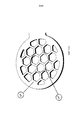
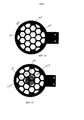
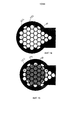
В некоторых вариантах осуществления, упомянутое одно или более отверстий аппликатора имеют шестиугольные конфигурации.In some embodiments, said one or more holes of the applicator have hexagonal configurations.
В некоторых вариантах осуществления, упомянутое одно или более отверстий опоры имеют шестиугольные конфигурации.In some embodiments, said one or more support holes have hexagonal configurations.
В некоторых вариантах осуществления, имплантат роговицы создан из гидрофильного материала.In some embodiments, the corneal implant is made from a hydrophilic material.
В одном аспекте, изобретение представляет собой устройство для аппликации имплантатов роговицы, содержащее аппликатор имплантатов с множеством отверстий аппликатора, проделанных сквозь него, и опору имплантатов с множеством отверстий опоры, проделанных сквозь нее, причем количество отверстий аппликатора в их множестве больше, чем количество отверстий опоры в их множестве, при этом аппликатор имплантатов и опора имплантатов расположены друг относительно друга так, что образуют гнездо для имплантатов роговицы, и при этом гнездо для имплантатов роговицы выполнено с возможностью заключения в нем имплантата роговицы таким образом, что имплантат роговицы располагается рядом с множеством отверстий аппликатора и множеством отверстий опоры.In one aspect, the invention is a device for applying corneal implants, comprising an implant applicator with a plurality of holes of an applicator made through it, and a support of implants with a plurality of holes of a support made through it, the number of holes of the applicator being more than the number of holes of the support in their set, while the implant applicator and the implant support are located relative to each other so that they form a nest for corneal implants, and at the same time an nest for imp antatov cornea is adapted to enter into the corneal implant therein so that the cornea implant is located near the applicator a plurality of openings and a plurality of support holes.
В некоторых вариантах осуществления, большее количество отверстий аппликатора обеспечивает аппликатор, у которого сродство к имплантату роговицы больше, чем у опоры.In some embodiments, implementation, a larger number of holes of the applicator provides an applicator, in which the affinity for the corneal implant is greater than the support.
В некоторых вариантах осуществления, аппликатор выполнен так, что у ткани роговицы сродство к имплантату роговицы больше, чем у аппликатора.In some embodiments, the applicator is configured such that there is more affinity for the corneal implant in the corneal tissue than in the applicator.
В некоторых вариантах осуществления, количество тех отверстий аппликатора в их множестве, которые перекрывают имплантат роговицы, когда тот расположен в гнезде, больше, чем количество тех отверстий опоры в их множестве, которые перекрывают имплантат роговицы, когда тот расположен в гнезде.In some embodiments, the number of those holes of the applicator in their set that overlap the corneal implant when it is located in the nest is greater than the number of those holes of the applicator in their set that overlap the corneal implant when it is located in the nest.
В некоторых вариантах осуществления, множество отверстий аппликатора имеют шестиугольные конфигурации.In some embodiments, the plurality of applicator holes have hexagonal configurations.
В некоторых вариантах осуществления, множество отверстий опоры имеют шестиугольные конфигурации.In some embodiments, implementation, many of the holes of the support have hexagonal configurations.
В некоторых вариантах осуществления, имплантат роговицы создан из гидрофильного материала.In some embodiments, the corneal implant is made from a hydrophilic material.
В одном аспекте, изобретение представляет собой устройство для аппликации имплантатов роговицы, содержащее аппликатор имплантатов роговицы с множеством отверстий аппликатора, проделанных сквозь него, причем множество отверстий аппликатора имеют шестиугольные конфигурации, и опору имплантатов роговицы с множеством отверстий опоры, проделанных сквозь нее, причем отверстия опоры в их множестве имеют шестиугольные конфигурации, при этом опора имплантатов роговицы расположена относительно аппликатора имплантатов роговицы так, что они образуют между собой гнездо для имплантатов роговицы.In one aspect, the invention is a device for applying corneal implants, comprising a corneal implant applicator with a plurality of applicator holes made through it, the plurality of applicator holes having hexagonal configurations, and a corneal implant support with a plurality of support holes made through it, wherein the support holes many of them have hexagonal configurations, while the corneal implant support is located relative to the corneal implant applicator so that they Braz between a socket for corneal implants.
В некоторых вариантах осуществления, размеры множества отверстий аппликатора обеспечивают аппликатор, у которого сродство к имплантату роговицы больше, чем у опоры.In some embodiments, the dimensions of the plurality of holes of the applicator provide an applicator in which the affinity for the corneal implant is greater than that of the support.
В некоторых вариантах осуществления, размеры отверстий аппликатора таковы, что у ткани роговицы сродство к имплантату роговицы больше, чем у аппликатора.In some embodiments, the hole sizes of the applicator are such that the affinity for the corneal implant for the corneal tissue is greater than for the applicator.
В некоторых вариантах осуществления, устройство дополнительно содержит имплантат роговицы, расположенный внутри гнезда рядом с множеством отверстий аппликатора и множеством отверстий опоры.In some embodiments, the device further comprises a corneal implant located inside the nest next to the plurality of holes of the applicator and the plurality of support holes.
В некоторых вариантах осуществления, линейный размер между противоположными сторонами шестиугольных отверстий аппликатора в их множестве меньше, чем линейный размер между противоположными сторонами шестиугольных отверстий опоры в их множестве.In some embodiments, the linear size between the opposite sides of the hexagonal holes of the applicator in their set is smaller than the linear size between the opposite sides of the hexagonal holes of the applicator in their set.
В некоторых вариантах осуществления, имплантат роговицы создан из гидрофильного материала.In some embodiments, the corneal implant is made from a hydrophilic material.
В одном аспекте, изобретение представляет собой устройство для аппликации имплантатов роговицы, содержащее аппликатор имплантатов, по меньшей мере, с одним отверстием аппликатора, проделанным сквозь него, и опору имплантатов, по меньшей мере, с одним отверстием опоры, проделанным сквозь нее, причем аппликатор имплантатов и опора имплантатов расположены друг относительно друга так, что образуют гнездо для имплантатов, которое приспособлено к заключению в нем имплантата роговицы, при этом упомянутое, по меньшей мере, одно отверстие аппликатора и упомянутое, по меньшей мере, одно отверстие опоры выполнены так, что силы между имплантатом роговицы и жидкостью, находящейся в упомянутом, по меньшей мере, одном отверстии аппликатора, больше, чем силы между имплантатом роговицы и жидкостью, находящейся в упомянутом, по меньшей мере, одном отверстии опоры, при этом большие силы обеспечивают аппликатор, у которого сродство к имплантату роговицы больше, чем у опоры.In one aspect, the invention is a device for applying corneal implants, comprising an implant applicator with at least one applicator hole made therethrough and an implant support with at least one support hole made through it, the implant applicator and the implant support are positioned relative to each other so as to form an implant socket that is adapted to enclose a corneal implant therein, wherein said at least one hole is an applique the ator and said at least one opening of the support are made so that the forces between the corneal implant and the fluid located in the said at least one hole of the applicator are greater than the forces between the corneal implant and the fluid located in the said at least at least one hole of the support, while greater force is provided by the applicator, in which the affinity for the corneal implant is greater than that of the support.
В некоторых вариантах осуществления, упомянутое, по меньшей мере, одно отверстие аппликатора способно обеспечить аппликатор, у которого сродство к имплантату роговицы меньше, чем у поверхности роговицы.In some embodiments, the at least one hole of the applicator mentioned can provide an applicator in which the affinity for the corneal implant is less than the surface of the cornea.
В некоторых вариантах осуществления, количество отверстий аппликатора больше, чем количество отверстий опоры. Количество отверстий аппликатора, которые перекрывают имплантат роговицы, когда тот расположен в гнезде для имплантатов, может быть больше, чем количество отверстий опоры, которые перекрывают имплантат роговицы.In some embodiments, implementation, the number of holes of the applicator is greater than the number of holes of the support. The number of holes of the applicator that overlap the corneal implant when it is located in the implant socket may be greater than the number of support holes that overlap the corneal implant.
В некоторых вариантах осуществления, размер упомянутого, по меньшей мере, одного отверстия аппликатора меньше, чем размер упомянутого, по меньшей мере, одного отверстия опоры.In some embodiments, implementation, the size of said at least one hole of the applicator is smaller than the size of said at least one hole of the support.
В некоторых вариантах осуществления, аппликатор имплантатов имеет первую поверхность, сквозь которую проходит упомянутое, по меньшей мере, одно отверстие аппликатора, причем эта первая поверхность является плоской.In some embodiments, the implant applicator has a first surface through which said at least one opening of the applicator passes, the first surface being flat.
В некоторых вариантах осуществления, опора имплантатов имеет первую поверхность, сквозь которую проходит упомянутое, по меньшей мере, одно отверстие опоры, причем эта первая поверхность является плоской.In some embodiments, the implant support has a first surface through which the at least one opening of the support passes, this first surface being flat.
В некоторых вариантах осуществления, отношение суммы периметров отверстий аппликатора, которых, по меньшей мере, одно, к сумме площадей отверстий аппликатора, которых, по меньшей мере, одно, больше, чем отношение суммы периметров отверстий опоры, которых, по меньшей мере, одно, к сумме площадей отверстий опоры, которых, по меньшей мере, одно, и при этом большее отношение обеспечивает аппликатор, у которого сродство к имплантату роговицы выше, чем у опоры.In some embodiments, implementation, the ratio of the sum of the perimeters of the holes of the applicator, of which at least one, to the sum of the areas of the holes of the applicator, of which at least one is greater than the ratio of the sum of the perimeters of the holes of the support, of which at least one to the sum of the areas of the holes of the support, of which at least one, and at the same time, an applicator has a greater ratio, in which the affinity for the corneal implant is higher than that of the support.
В некоторых вариантах осуществления, упомянутое, по меньшей мере, одно отверстие аппликатора и упомянутое, по меньшей мере, одно отверстие опоры имеют шестиугольные конфигурации.In some embodiments, the at least one hole of the applicator and the at least one hole of the support have hexagonal configurations.
В некоторых вариантах осуществления, аппликатор имплантатов имеет множество отверстий аппликатора, проделанных сквозь него, и опора имплантатов имеет множество отверстий опоры, проделанных сквозь нее, причем отверстия аппликатора в их множестве меньше, чем отверстия опоры в их множестве.In some embodiments, the implant applicator has a plurality of applicator holes made through it, and the implant support has a plurality of support holes made through it, and the applicator holes in their plurality are smaller than the support openings in their plurality.
В некоторых вариантах осуществления, аппликатор имплантатов имеет множество отверстий аппликатора, проделанных сквозь него, и опора имплантатов имеет множество отверстий опоры, проделанных сквозь нее, и при этом количество тех отверстий аппликатора в их множестве, которые перекрывают имплантат роговицы, когда имплантат роговицы расположен в гнезде, больше, чем количество тех отверстий опоры в их множестве, которые перекрывают имплантат роговицы.In some embodiments, the implant applicator has a plurality of applicator openings made through it, and the implant support has a plurality of support openings made through it, and the number of those applicator openings in their set that overlap the corneal implant when the corneal implant is located in the socket , more than the number of those support holes in their set that overlap the corneal implant.
В некоторых вариантах осуществления, имплантат роговицы создан из гидрофильного материала.In some embodiments, the corneal implant is made from a hydrophilic material.
В одном аспекте, изобретение представляет собой устройство для аппликации имплантатов роговицы, содержащее аппликатор имплантатов с множеством отверстий аппликатора, проделанных сквозь него, и опору имплантатов с множеством отверстий опоры, проделанных сквозь нее, причем аппликатор имплантатов и опора имплантатов расположены друг относительно друга так, что образуют гнездо для имплантатов, выполненное с возможностью заключения в нем имплантата роговицы, и при этом расположение множества отверстий аппликатора обеспечивает аппликатор, у которого сродство к имплантату роговицы выше, чем у опоры.In one aspect, the invention is a device for applying corneal implants, comprising an implant applicator with a plurality of holes of an applicator made through it, and an implant support with a plurality of support holes made through it, wherein the implant applicator and the implant support are located relative to each other so that form a nest for implants, configured to enclose a corneal implant in it, and the location of the multiple holes of the applicator provides applicato p, in which the affinity for the corneal implant is higher than that of the support.
В некоторых вариантах осуществления, расположение множества отверстий аппликатора обеспечивает аппликатор, у которого сродство к имплантату роговицы меньше, чем у поверхности роговицы.In some embodiments, the location of the plurality of holes of the applicator provides an applicator in which the affinity for the corneal implant is less than the surface of the cornea.
В некоторых вариантах осуществления, количество отверстий аппликатора больше, чем количество отверстий опоры. Количество отверстий аппликатора, которые перекрывают имплантат роговицы, когда тот расположен в гнезде для имплантатов, может быть больше, чем количество отверстий опоры, которые перекрывают имплантат роговицы.In some embodiments, implementation, the number of holes of the applicator is greater than the number of holes of the support. The number of holes of the applicator that overlap the corneal implant when it is located in the implant socket may be greater than the number of support holes that overlap the corneal implant.
В некоторых вариантах осуществления, размер отверстий аппликатора в их множестве меньше, чем размер отверстий опоры в их множестве.In some embodiments, implementation, the size of the holes of the applicator in their set is smaller than the size of the holes of the support in their set.
В некоторых вариантах осуществления, аппликатор имплантатов имеет первую поверхность, сквозь которую проходят множество отверстий аппликатора, причем эта первая поверхность является плоской.In some embodiments, the implant applicator has a first surface through which a plurality of holes of the applicator pass, moreover, this first surface is flat.
В некоторых вариантах осуществления, опора имплантатов имеет первую поверхность, сквозь которую проходят множество отверстий опоры, причем эта первая поверхность является плоской.In some embodiments, the implant support has a first surface through which a plurality of support holes pass, this first surface being flat.
В некоторых вариантах осуществления, отношение суммы периметров множества отверстий аппликатора к сумме площадей множества отверстий аппликатора больше, чем отношение суммы периметров множества отверстий опоры к сумме площадей множества отверстий опоры, и при этом большее отношение обеспечивает аппликатор, у которого сродство к имплантату роговицы выше, чем у опоры.In some embodiments, the ratio of the sum of the perimeters of the plurality of holes of the applicator to the sum of the areas of the plurality of holes of the applicator is greater than the ratio of the sum of the perimeters of the plurality of holes of the abutment to the sum of the areas of the plurality of holes of the abutment, and the applicator has a higher ratio of affinity for the corneal implant than at the support.
В некоторых вариантах осуществления, множество отверстий аппликатора и множество отверстий опоры имеют шестиугольные конфигурации.In some embodiments, the plurality of applicator holes and the plurality of support holes have hexagonal configurations.
В некоторых вариантах осуществления, отверстия аппликатора в их множестве меньше, чем отверстия опоры в их множестве.In some embodiments, implementation, the holes of the applicator in their set is smaller than the holes of the support in their set.
В некоторых вариантах осуществления, количество тех отверстий аппликатора в их множестве, которые перекрывают имплантат роговицы, когда имплантат роговицы расположен в гнезде, больше, чем количество тех отверстий опоры в их множестве, которые перекрывают имплантат роговицы.In some embodiments, the number of those openings of the applicator in their set that overlap the corneal implant when the corneal implant is located in the nest is greater than the number of those support holes in their set that overlap the corneal implant.
В некоторых вариантах осуществления, имплантат роговицы создан из гидрофильного материала.In some embodiments, the corneal implant is made from a hydrophilic material.
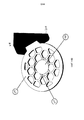
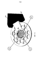
В одном аспекте, изобретение представляет собой устройство управления гидратацией имплантатов роговицы, содержащее корпус, образующий карман, конфигурация которого обеспечивает прием и стабилизацию в нем устройства для подачи имплантатов роговицы.In one aspect, the invention is a device for controlling the hydration of corneal implants, comprising a housing forming a pocket, the configuration of which provides reception and stabilization of a device for delivering corneal implants therein.
В некоторых вариантах осуществления, корпус содержит первый управляющий гидратацией элемент и второй управляющий гидратацией элемент, расположенный относительно первого управляющего гидратацией элемента так, что они образуют карман. Первый и второй управляющие гидратацией элементы могут содержать секции скатанного в рулон материала. Первый и второй управляющие гидратацией элементы могут содержать секции скатанного в рулон материала из цельного отреза материала. Цельный отрез материала может образовывать задний упор. Первый и второй управляющие гидратацией элементы могут иметь в целом цилиндрическую форму. Первый и второй управляющие гидратацией элементы могут быть введены в контакт друг с другом.In some embodiments, the housing comprises a first hydration control element and a second hydration control element located relative to the first hydration control element so that they form a pocket. The first and second hydration control elements may comprise sections of rolled material. The first and second hydration control elements may comprise sections of rolled material from a single cut of material. A single piece of material can form a back stop. The first and second hydration control elements may have a generally cylindrical shape. The first and second hydration control elements can be brought into contact with each other.
В некоторых вариантах осуществления, устройство дополнительно содержит первое деформируемое основание, прикрепленное к корпусу, причем первое деформируемое основание выполнено с возможностью регулирования расстояния между первым управляющим гидратацией элементом и вторым управляющим гидратацией элементом, при этом первый и второй управляющие гидратацией элементы образуют, по меньшей мере, участок кармана. Устройство может дополнительно содержать первый сердечник, расположенный внутри первого управляющего гидратацией элемента, и второй сердечник, расположенный внутри второго управляющего гидратацией элемента, причем первое деформируемое основание прикреплено к первому и второму сердечникам для крепления к первому и второму управляющим гидратацией элементам. Устройство может дополнительно содержать второе деформируемое основание, прикрепленное к первому и второму сердечникам. Первое деформируемое основание может быть прикреплено к первому концу каждого из первого и второго сердечников, а второе деформируемое основание может быть прикреплено ко второму концу каждого из первого и второго сердечников. Первое деформируемое основание может включать в себя гибкий шарнир, который обеспечивает деформацию этого деформируемого основания для регулирования расстояния между первым и вторым управляющим гидратацией элементами.In some embodiments, the device further comprises a first deformable base attached to the body, wherein the first deformable base is configured to adjust the distance between the first hydration control element and the second hydration control element, wherein the first and second hydration control elements form at least pocket section. The device may further comprise a first core located inside the first hydration control element and a second core located inside the second hydration control element, the first deformable base being attached to the first and second cores for attachment to the first and second hydration control elements. The device may further comprise a second deformable base attached to the first and second cores. The first deformable base may be attached to the first end of each of the first and second cores, and the second deformable base may be attached to the second end of each of the first and second cores. The first deformable base may include a flexible hinge that deforms this deformable base to control the distance between the first and second hydration control elements.
В некоторых вариантах осуществления, карман имеет общую форму клина, образованного первым и вторым управляющими гидратацией элементами.In some embodiments, the pocket has the general shape of a wedge formed by the first and second hydration control elements.
В некоторых вариантах осуществления, корпус выполнен из материала сложного полиэфира.In some embodiments, the housing is made of polyester material.
В некоторых вариантах осуществления, корпус выполнен с возможностью впитывания текучей среды устройства, расположенного внутри кармана, когда устройство извлекают из кармана.In some embodiments, the housing is configured to absorb fluid from the device located inside the pocket when the device is removed from the pocket.
В одном аспекте, изобретение представляет собой упаковочный узел для аппликатора имплантатов роговицы, содержащий устройство для аппликации имплантатов роговицы, содержащее участок для имплантатов, на котором удерживается имплантат, и управляющее гидратацией приспособление, содержащее карман, который выполнен с возможностью приема и стабилизации в нем участка для имплантатов.In one aspect, the invention is a packaging assembly for a corneal implant applicator, comprising a device for applying corneal implants, comprising an implant portion on which the implant is held, and a hydration control device comprising a pocket that is adapted to receive and stabilize the portion for implants.
В некоторых вариантах осуществления, участок для имплантатов, на котором удерживается имплантат роговицы, является, по существу, плоским.In some embodiments, the implant portion on which the corneal implant is held is substantially flat.
В некоторых вариантах осуществления, имплантат роговицы удерживается на участке для имплантатов устройства для аппликации имплантатов роговицы, по существу, в ненапряженной конфигурации.In some embodiments, the corneal implant is held at the implant site of the corneal implant applicator device in a substantially unstressed configuration.
В некоторых вариантах осуществления, управляющее гидратацией приспособление содержит первый управляющий гидратацией элемент и второй управляющий гидратацией элемент, причем первый и второй управляющие гидратацией элементы образуют, по меньшей мере, участок кармана. Первый и второй управляющие гидратацией элементы имеют в целом цилиндрическую форму.In some embodiments, the hydration control device comprises a first hydration control element and a second hydration control element, wherein the first and second hydration control elements form at least a portion of the pocket. The first and second hydration control elements are generally cylindrical.
В некоторых вариантах осуществления, управляющее гидратацией приспособление дополнительно содержит задний упор, выполненный с возможностью предотвращения продвижения устройства для аппликации имплантатов роговицы слишком далеко внутрь кармана.In some embodiments, the hydration control device further comprises a backstop configured to prevent the device for applying corneal implants from moving too far into the pocket.
В некоторых вариантах осуществления, первый и второй управляющие гидратацией элементы выполнены с возможностью, отодвигания друг от друга для размещения между ними устройства для аппликации имплантатов роговицы.In some embodiments, the first and second hydration control elements are movable apart from each other to accommodate a device for applying corneal implants between them.
В одном аспекте, изобретение представляет собой способ удаления избыточной консервационной жидкости из устройства для аппликации имплантатов роговицы, заключающийся в том, что обеспечивают устройство для аппликации имплантатов роговицы, в котором имплантат роговицы расположен в пределах участка устройства; и счищают избыточную текучую среду с этого участка устройства путем введения участка устройства, на котором расположен имплантат, в контакт с управляющим гидратацией приспособлением, перемещая при этом участок устройства относительно управляющего гидратацией приспособления.In one aspect, the invention is a method for removing excess preservation fluid from a device for applying corneal implants, comprising: providing a device for applying corneal implants, wherein the corneal implant is located within a portion of the device; and remove excess fluid from this portion of the device by introducing the portion of the device on which the implant is placed into contact with the hydration control device, while moving the portion of the device relative to the hydration control device.
В некоторых вариантах осуществления, упомянутый участок устройства включает в себя первую и вторую поверхности, каждая из которых имеет, по меньшей мере, одно отверстие, выполненное в ней, причем первая и вторая поверхности образуют гнездо для роговицы, при этом этап счистки включает в себя удаление избыточной текучей среды с первой и второй поверхностей.In some embodiments, said portion of the device includes first and second surfaces, each of which has at least one opening formed therein, the first and second surfaces forming a corneal socket, wherein the cleansing step includes removing excess fluid from the first and second surfaces.
В некоторых вариантах осуществления, этап счистки включает в себя введение участка устройства в контакт с первым и вторым управляющим гидратацией элементами при одновременном перемещении участка устройства относительно первого и второго управляющих гидратацией элементов.In some embodiments, the cleaning step includes bringing a portion of the device into contact with the first and second hydration control elements while simultaneously moving the portion of the device relative to the first and second hydration control elements.
В одном аспекте, изобретение представляет собой способ хранения устройства для аппликации имплантатов роговицы, заключающийся в том, что обеспечивают устройство для аппликации имплантатов роговицы с первым участком, на котором расположен имплантат роговицы, и позиционируют первый участок устройства в карман, образованный управляющим гидратацией приспособлением, до тех пор, пока первый участок не вступает в контакт с управляющим гидратацией приспособлением.In one aspect, the invention is a method of storing a device for applying corneal implants, comprising providing a device for applying corneal implants with a first portion on which a corneal implant is located, and positioning the first portion of the device in a pocket formed by the hydration control device until until the first portion comes into contact with the hydration control device.
В некоторых вариантах осуществления, этап позиционирования предусматривает установление сообщения по текучей среде между управляющим гидратацией приспособлением и имплантатом роговицы.In some embodiments, the positioning step involves establishing a fluid communication between the hydration control device and the corneal implant.
В некоторых вариантах осуществления, этап позиционирования включает в себя продвижение первого участка в карман, образованный двумя управляющими гидратацией элементами, до тех пор, пока первый участок не вступает в контакт с обоими управляющими гидратацией элементами. Этап позиционирования может включать в себя позиционирование первой поверхности устройства с введением ее в контакт с первым управляющим гидратацией элементом и позиционирование второй поверхности устройства с введением ее в контакт со вторым управляющим гидратацией элементом.In some embodiments, the positioning step includes moving the first portion into a pocket formed by two hydration control elements until the first portion comes into contact with both hydration control elements. The positioning step may include positioning the first surface of the device with bringing it into contact with the first hydration control element and positioning the second surface of the device with bringing it into contact with the second hydration control element.
КРАТКОЕ ОПИСАНИЕ ЧЕРТЕЖЕЙBRIEF DESCRIPTION OF THE DRAWINGS
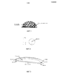
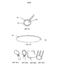
Фиг. 1 иллюстрирует возможные силы когезии.FIG. 1 illustrates possible cohesion forces.
фиг. 2 иллюстрирует возможные силы адгезии.FIG. 2 illustrates possible adhesion forces.
Фиг. 3 иллюстрирует жидкость, суспендированную внутри контура.FIG. 3 illustrates a fluid suspended inside a circuit.
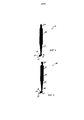
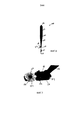
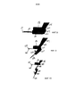
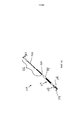
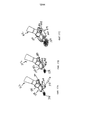
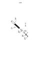
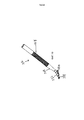
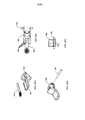
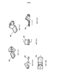
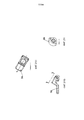
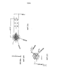
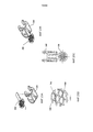
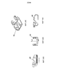
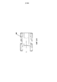
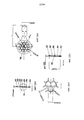
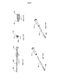
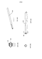
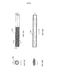
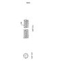
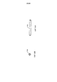
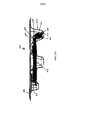
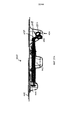
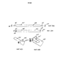
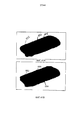
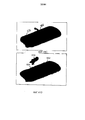
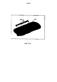
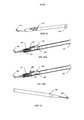
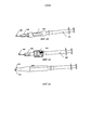
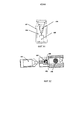
Фиг. 4 - 10 иллюстрируют возможное устройство для аппликации имплантатов роговицы.FIG. 4-10 illustrate a possible device for the application of corneal implants.
Фиг. 11А-15 иллюстрируют возможные корпуса, имеющие умеренное и минимальное сродство.FIG. 11A-15 illustrate possible bodies having moderate and minimal affinity.
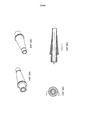
Фиг. 16-19 иллюстрируют возможное устройство для аппликации имплантатов роговицы.FIG. 16-19 illustrate a possible device for the application of corneal implants.
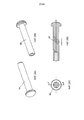
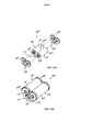
Фиг. 20А-32В иллюстрируют компоненты возможного устройства для аппликации имплантатов роговицы.FIG. 20A-32B illustrate components of a possible device for applying corneal implants.
Фиг. 33А-33В иллюстрируют участок возможного устройства для аппликации имплантатов роговицы, расположенного внутри кармана управляющего гидратацией приспособления и внутри упаковочного лотка.FIG. 33A-33B illustrate a portion of a possible device for the application of corneal implants located inside the hydration control pocket of the device and inside the packaging tray.
Фиг. 34-36В иллюстрируют возможные управляющие гидратацией приспособления.FIG. 34-36B illustrate possible hydration control devices.
Фиг. 37А-37В иллюстрируют участок возможного устройства для аппликации имплантатов роговицы, расположенного внутри кармана управляющего гидратацией приспособления и внутри упаковочного лотка.FIG. 37A-37B illustrate a portion of a possible device for applying corneal implants located inside the hydration control pocket of the device and inside the packaging tray.
Фиг. 38А-40В иллюстрируют возможное управляющее гидратацией приспособление.FIG. 38A-40B illustrate a possible hydration control device.
Фиг. 41А-41Е иллюстрируют возможное упаковочное устройство.FIG. 41A-41E illustrate a possible packaging device.
Фиг. 42 иллюстрирует возможный контур для позиционирования имплантатов роговицы.FIG. 42 illustrates a possible contour for positioning corneal implants.
Фиг. 43 иллюстрирует возможный имплантат роговицы.FIG. 43 illustrates a possible corneal implant.
Фиг. 44A-44D иллюстрируют возможные контуры.FIG. 44A-44D illustrate possible contours.
Фиг. 45-54 иллюстрируют возможные приспособления для позиционирования имплантатов роговицы.FIG. 45-54 illustrate possible adaptations for positioning corneal implants.
ПОДРОБНОЕ ОПИСАНИЕDETAILED DESCRIPTION
Изобретение относится к устройствам одного или более таких назначений, как упаковка, хранение, позиционирование и подача имплантатов роговицы, таких, как роговичные вкладки. Описываемые здесь устройства можно использовать при перемещении и позиционировании, например - но не в ограничительном смысле, роговичных накладок, роговичных вкладок, протезов роговицы и контактных линз.The invention relates to devices for one or more purposes, such as packaging, storage, positioning and delivery of corneal implants, such as corneal inlays. The devices described herein can be used when moving and positioning, for example, but not limited to, corneal pads, corneal inlays, corneal prostheses, and contact lenses.
Изобретение включает в себя устройства и способы, применение которых основано, по меньшей мере - частично, на поверхностном натяжении жидкостей и имеет целью управление позиционированием и/или перемещением имплантата роговицы. Эти устройства можно применять при хранении, упаковке, перемещении или подаче имплантатов роговицы. Этими подходами можно воспользоваться, когда имплантат роговицы создан, по меньшей мере - частично, из гидрофильного материала, такого, как гидрогель.The invention includes devices and methods, the use of which is based, at least in part, on the surface tension of fluids and is intended to control the positioning and / or movement of the corneal implant. These devices can be used for storing, packaging, moving or delivering corneal implants. These approaches can be used when the corneal implant is created, at least in part, from a hydrophilic material, such as a hydrogel.
Поверхностное натяжение является свойством жидкостей, которое позволяет массе жидкости сопротивляться внешним силам. Именно оно позволяет объектам плотнее воды, таким, как мелкие частицы мусора или некоторые насекомые, плавать на поверхности жидкости. Поверхностное натяжение обуславливается силами когезии молекул жидкости. Силы когезии - это силы притяжения между двумя похожими молекулами. Как показано на фиг. 1, средняя молекула в пределах массы жидкости не имеет общей силы когезии, действующей на нее, потому что она испытывает воздействие сил когезии, действующих на нее со стороны соседних молекул в каждом направлении. Вместе с тем, молекула на поверхности подвергается воздействию только тех сил когезии, которые увлекают ее внутрь массы. В случае очень малых капель, направленная внутрь сила, действующая на все молекулы, находящиеся на поверхности, вызывает придание капле в целом сферической формы.Surface tension is a property of fluids that allows a mass of fluid to resist external forces. It is it that allows objects denser than water, such as small particles of debris or some insects, to float on the surface of a liquid. Surface tension is determined by the cohesion of liquid molecules. Cohesion forces are the forces of attraction between two similar molecules. As shown in FIG. 1, the middle molecule within the mass of the liquid does not have a common cohesion force acting on it, because it is affected by the cohesion forces acting on it by neighboring molecules in each direction. At the same time, the molecule on the surface is exposed only to those cohesion forces that carry it into the mass. In the case of very small droplets, an inwardly directed force acting on all molecules located on the surface causes the droplet to give a generally spherical shape.
С другой стороны, силы адгезии - это силы, действующие между непохожими молекулами. В случае некоторых сочетаний материалов, эти силы могут быть больше, чем силы когезии молекул жидкости. Именно значительные силы адгезии являются причиной «изгиба» кверху, называемого мениском (как показано на фиг. 2), на поверхности жидкости там, где жидкость вокруг края контейнера поднимается выше, чем на остальной поверхности, за счет сил адгезии между жидкостью и контейнером. Силы адгезии действуют на поверхность воды в направлении вверх и находятся в равновесии с силами тяжести, действующими на массу жидкости в направлении вниз.Adhesion forces, on the other hand, are forces acting between dissimilar molecules. In the case of some combinations of materials, these forces may be greater than the cohesion forces of liquid molecules. It is the significant adhesion forces that cause the “bending” upward, called the meniscus (as shown in Fig. 2), on the surface of the liquid where the liquid around the edge of the container rises higher than on the rest of the surface due to the adhesion forces between the liquid and the container. The adhesion forces act on the surface of the water in the upward direction and are in equilibrium with the forces of gravity acting on the mass of liquid in the downward direction.
В случае жидкости, суспендированной внутри контура, как показано на фиг. 3, силы адгезии со стороны контура действуют и на верхнюю, и на нижнюю поверхности жидкости, а силы когезии действуют и по верхней, и по нижней поверхностям. Эти силы достаточны для удержания жидкости в пределах контура до тех пор, пока объем жидкости не окажется настольно большим, что силы тяжести превысят силы когезии и адгезии.In the case of a liquid suspended inside the circuit, as shown in FIG. 3, the adhesion forces on the side of the circuit act on both the upper and lower surfaces of the liquid, and the cohesion forces act on both the upper and lower surfaces. These forces are sufficient to hold the fluid within the circuit until the fluid volume is so large that the forces of gravity exceed the forces of cohesion and adhesion.
В случае сплошной, сетчатой или иной такой поверхности, силы адгезии и когезии действуют аналогичным образом. Многие факторы, включая тип материала, тип текучей среды и геометрию поверхности, будут влиять на величину сил адгезии и когезии.In the case of a continuous, mesh or other such surface, the adhesion and cohesion forces act in a similar way. Many factors, including the type of material, type of fluid, and surface geometry, will affect the magnitude of the adhesion and cohesion forces.
Возможные имплантаты роговицы, которые можно хранить и применять в соответствии с нижеследующими вариантами осуществления, представляют собой роговичные вкладки, описанные в публикации США № US 2007/0203577, заявленной 30 октября 2006 г., публикации США № US 2008/0262610, заявленной 20 апреля 2007 г., и публикации США № 2011/0218623, заявленной 8 сентября 2010 г., описания которых включены сюда посредством ссылки. В некоторых вариантах осуществления, роговичная вкладка «малого диаметра» (т.е., между примерно 1 мм и примерно 3 мм) создана из гидрогеля, который может быть изначально текучей средой. Это, а также малый размер вкладки, заставляет это вещество вести себя в чем-то так же, как текучая среда. Приводимое ниже описание предусматривает употребление этих характеристик имплантата роговицы и определений сил адгезии между текучей средой и поверхностями, имеющими различные геометрии. Хотя в приводимом здесь описании основное внимание уделяется роговичным вкладкам, в том смысле, о котором здесь идет речь, можно применять любой имплантат роговицы, который демонстрирует аналогичные свойства. Например, в том смысле, о котором здесь идет речь, можно применять роговичные накладки, по меньшей мере, участок которых обладает гидрофильными свойствами.Possible corneal implants that can be stored and used in accordance with the following embodiments are corneal tabs described in US Publication No. US 2007/0203577, October 30, 2006, US Publication No. US 2008/0262610, April 20, 2007 , and US publication No. 2011/0218623, claimed September 8, 2010, descriptions of which are incorporated here by reference. In some embodiments, the “small diameter” corneal tab (ie, between about 1 mm and about 3 mm) is made from a hydrogel, which may be initially a fluid. This, as well as the small size of the tab, makes this substance behave in something like a fluid. The following description provides for the use of these characteristics of a corneal implant and definitions of the adhesion forces between a fluid and surfaces having different geometries. Although the description given here focuses on the corneal inlays, in the sense discussed here, any corneal implant that exhibits similar properties can be used. For example, in the sense in question, it is possible to use corneal lining, at least a portion of which has hydrophilic properties.
Устройства, о которых здесь идет речь, основаны на «сродстве» корпуса с текучей средой или объектом со свойствами, подобными свойствам текучей среды (например, гидрофильным имплантатом роговицы). В том смысле, в как это понятие употребляется здесь, на «сродство» корпуса с текучей средой или объектом, подобным текучей среде, влияет разность между величиной результирующих сил адгезии между корпусом и текучей средой или объектом, подобным текучей среде, и величиной результирующих сил когезии в пределах и текучей среды или объектам подобного текучей среде. В приводимых здесь вариантах осуществления, где предусматривается наличие, по существу, неизменной текучей среды или неизменного объекта, подобного текучей среде (например, гидрофильной роговичной вкладки), относительное сродство двух корпусов с текучей средой или объектом, подобным текучей среде, по меньшей мере, частично определяется относительными величинами результирующих сил адгезии между корпусами и текучей средой или объектом, подобным текучей среде. Например, в варианте осуществления, в котором объект, подобный текучей среде, представляет собой гидрофильный имплантат роговицы, первый корпус может иметь большее сродство к имплантату, чем второй корпус, когда результирующие силы адгезии между первым корпусом и имплантатом больше, чем результирующие силы адгезии между вторым корпусом и имплантатом.The devices in question are based on the "affinity" of the body with a fluid or object with properties similar to those of a fluid (for example, a hydrophilic corneal implant). In the sense that this concept is used here, the “affinity” of a body with a fluid or an object similar to a fluid is affected by the difference between the value of the resulting adhesion forces between the body and a fluid or an object similar to a fluid and the value of the resulting cohesion forces within and fluid or objects like a fluid. In the embodiments provided herein, where it is contemplated that a substantially constant fluid or fluid-like object (e.g., a hydrophilic corneal insert) is present, the relative affinity of the two bodies with a fluid or fluid-like object is at least partially is determined by the relative values of the resulting adhesion forces between the bodies and the fluid or an object similar to the fluid. For example, in an embodiment in which the fluid-like object is a hydrophilic corneal implant, the first body may have a greater affinity for the implant than the second body, when the resulting adhesion forces between the first body and the implant are greater than the resulting adhesion forces between the second body and implant.
Имплантат роговицы останется прилипшим к корпусу с наибольшей результирующей силой (суммой сил адгезии и когезии).The corneal implant will remain adhered to the body with the greatest resulting force (the sum of the adhesion and cohesion forces).
Первый корпус, именуемый здесь «корпусом, имеющим умеренное сродство», имеет большее сродство к текучей среде или объекту, подобному текучей среде, чем второй корпус, именуемый здесь «корпусом, имеющим минимальное сродство». В том контексте смысле, в каком термин «корпус» употребляется в здесь, его можно употреблять взаимозаменяемо с терминами «устройство», «компонент», «структура» или другим аналогичным термином для указания чего-либо со «структурой». Вместе с тем, у глаза сродство к текучей среде или объекту, подобному текучей среде, больше, чем у корпуса, имеющего умеренное сродство. Для манипуляций с вкладкой и управления перемещением вкладки, когда ее перемещают от одной поверхности к другой, а пользователю при этом не нужно касаться ее рукой или - в ином случае - инструментом, можно использовать разные относительные сродства. Факторы, которые влияют на относительные сродства, включают в себя один или более из: типа материала, типа текучей среды и геометрии поверхности, включая площадь поверхности.The first casing, referred to herein as “a casing having moderate affinity”, has a greater affinity for a fluid or fluid-like object than the second casing, referred to herein as “a casing having minimal affinity”. In the context of the sense in which the term “housing” is used here, it can be used interchangeably with the terms “device”, “component”, “structure” or another similar term to indicate something with “structure”. However, the affinity of the eye to a fluid or object similar to a fluid is greater than that of a body having a moderate affinity. You can use different relative affinities to manipulate the tab and control the movement of the tab when it is moved from one surface to another, while the user does not need to touch it with his hand or, otherwise, with a tool. Factors that affect relative affinities include one or more of: type of material, type of fluid, and surface geometry, including surface area.
В том смысле, в каком она применяется в данном изобретении, роговичная вкладка (например, объект, подобный текучей среде) имеет большее «сродство» к слою роговицы глаза, чем к корпусу, имеющего умеренное сродство, и при этом вкладка имеет большее сродство к корпусу, имеющего умеренное сродство, чем к корпусу, имеющему минимальное сродство. Глаз можно описать как имеющий большее сродство к вкладке, чем и корпус, имеющий умеренное сродство, и корпус, имеющий минимальное сродство. Аналогичным образом, корпус, имеющий умеренное сродство можно описать как имеющий большее сродство к вкладке, чем корпус, имеющий минимальное сродство. То есть, сродство между двумя корпусами можно описать относительно любого из них. Иными словами, например, корпус, имеющий умеренное сродство имеет большее сродство к вкладке, чем корпус, имеющий минимальное сродство, и поэтому вкладка предпочтительно будет прилипать к корпусу, имеющего умеренное сродство, а не к корпусу, имеющему минимальное сродство.In the sense in which it is used in this invention, the corneal tab (for example, an object similar to a fluid) has a greater "affinity" for the corneal layer of the eye than for a body with moderate affinity, and the tab has a greater affinity for the body having moderate affinity than to a body having minimal affinity. An eye can be described as having a greater affinity for a tab than both a corpus having moderate affinity and a corpus having minimal affinity. Similarly, a case having a moderate affinity can be described as having a greater affinity for a tab than a case having a minimum affinity. That is, the affinity between two buildings can be described with respect to any of them. In other words, for example, a case having a moderate affinity has a greater affinity for a tab than a case having a minimum affinity, and therefore, the tab will preferably adhere to a case having a moderate affinity rather than a case having a minimum affinity.
В некоторых вариантах осуществления, консервационная текучая среда представляет собой, например, воду или соляной раствор. Молекулы воды являются высоко-поляризованными, что обеспечивает силы притяжения ее к другим материалам.In some embodiments, the preservation fluid is, for example, water or saline. Molecules of water are highly polarized, which provides its attractive forces to other materials.
Относительное сравнение сродства между каждым корпусом и вкладкой можно представить неравенством: ткань роговицы > корпус, имеющий умеренное сродство > корпус, имеющий минимальное сродство. Корпуса, имеющие умеренное и минимальное сродство, могут принимать многие формы, включая - но не в ограничительном смысле - сита, мембраны и/или могут представлять собой материал с разными отделками поверхности или контурами.A relative comparison of affinity between each body and tab can be represented by the inequality: corneal tissue> body with moderate affinity> body with minimal affinity. Housings having moderate and minimal affinity can take many forms, including - but not limited to - sieves, membranes and / or can be a material with different surface finishes or contours.
Благодаря различиям в сродстве между корпусом, имеющим минимальное сродство, и корпусом, имеющим умеренное сродство, вкладка предпочтительно остается прилипшей к корпусу, имеющему умеренное сродство. Она продолжает прилипать к корпусу, имеющего умеренное сродство, до тех пор, пока не подвергнется воздействию большей силы адгезии. Поэтому корпуса, имеющие умеренное и минимальное сродство, могут быть выполнены из любого материала при условии, что силы адгезии между корпусом, имеющим умеренное сродство, и вкладкой больше, чем силы адгезии между корпусом, имеющим минимальное сродство, и вкладкой. Корпус, имеющий умеренное сродство, имеет большее сродство к вкладке, чем корпус, имеющий минимальное сродство, а адгезивные свойства материалов представляют собой фактор, влияющий на эти сродства.Due to differences in affinity between the case having a minimum affinity and the case having a moderate affinity, the tab preferably remains adhered to the case having a moderate affinity. She continues to adhere to the body, with moderate affinity, until it is exposed to a greater adhesion force. Therefore, housings having moderate and minimal affinity can be made of any material, provided that the adhesion forces between the housing having moderate affinity and the tab are greater than the adhesion forces between the housing having minimal affinity and the tab. A casing having a moderate affinity has a greater affinity for a tab than a casing having a minimal affinity, and the adhesive properties of materials are a factor affecting these affinities.
Фиг. 4-11D иллюстрируют возможный вариант осуществления устройства, которое содержит корпус, имеющий умеренное сродство, и корпус, имеющий минимальное сродство, причем устройство также включает в себя исполнительный механизм, который используется для отделения корпуса, имеющего минимальное сродство, от имплантата роговицы и корпуса, имеющего умеренное сродство. Устройство можно использовать для хранения имплантата роговицы, подготовки имплантата роговицы к подаче, и/или подачи имплантата роговицы на или в глаз. Фиг. 4 и 5 (вид сбоку и сечение на виде сбоку, соответственно) иллюстрируют устройство 100, включающее в себя рукоятку 112, прикрепленную к дистальному участку 114. В рукоятке 112 и дистальном участке 114 расположен исполнительный механизм 116, причем и рукоятка, и дистальный участок выполнены с возможностью пропускания сквозь них исполнительного механизма 116. Пружина 126 поддерживает исполнительный механизм 116 в конфигурации, соответствующей положению покоя или нерабочему положению и показанной на фиг. 4 и 5. Исполнительный механизм 116 имеет дистальную секцию 128 меньшего размера, которая расположена в дистальном канале меньшего размера на дистальном участке 114.FIG. 4-11D illustrate a possible embodiment of a device that comprises a body having moderate affinity and a body having minimal affinity, the device also including an actuator that is used to separate the body having minimal affinity from the corneal implant and the body having moderate affinity. The device can be used to store a corneal implant, prepare the corneal implant for delivery, and / or deliver the corneal implant to or in the eye. FIG. 4 and 5 (side view and sectional side view, respectively) illustrate a
Дистальный конец устройства 100 включает в себя первый участок 118, прикрепленный к корпусу 122, имеющему умеренное сродство. Второй участок 120 прикреплен к корпусу 124, имеющему минимальное сродство, а также прикреплен с возможностью открепления к первому участку 118 вокруг пальца 134. Имплантат роговицы (не показанный на фиг. 4 и 5 для ясности изображения) расположен между корпусом, имеющим умеренное сродство, и корпусом, имеющим минимальное сродство, в гнезде, образованном корпусами, имеющими умеренное и минимальное сродство. Второй участок 120 выполнен с возможностью вращения относительно первого участка 118 вокруг пальца 134. Фиг. 6 (сечение на виде сбоку) иллюстрирует устройство после нажима вниз на исполнительный механизм 116. Когда нажимают на исполнительный механизм 116, пружина 126 сжимается, а дистальный участок 128 перемещается вперед или - дистально - по каналу на дистальном участке 114. Дистальный конец дистальной секции 128 контактирует со вторым участком 120, принудительно отводя его вниз, когда он вращается вокруг пальца 134. Поскольку имплантат роговицы имеет большее сродство к корпусу 122, имеющему умеренное сродство, чем к корпусу 124, имеющему минимальное сродство, имплантат роговицы останется прилипшим к корпусу 122, имеющему умеренное сродство, когда второй участок 120 и корпус 124, имеющий минимальное сродство, поворачиваются в направлении от первого участка 118 и корпуса 122, имеющего умеренное сродство. Как только криволинейная часть второго участка 120 минует палец 134, второй участок 120 открепляется от первого участка 118, а значит - и от устройства 100, подготавливая имплантат роговицы для подачи (или - в некоторых вариантах осуществления - имплантат роговицы подается с помощью отдельного подающего устройства).The distal end of the
На фиг. 7 показано перспективное изображение дистальной области устройства 100, Первый участок 118 прикреплен ко второму участку 120 с помощью скобы 132, которая переведена в сомкнутую конфигурацию, показанную на фиг. 7. Когда со стороны исполнительного механизма 116 прикладывается сила срабатывания, скоба 132 принудительно переводится в разомкнутую конфигурацию, обеспечивая поворот второго участка 120 и корпуса 124, имеющего минимальное сродство, в направлении от первого участка 118.In FIG. 7 is a perspective view of a distal region of the
На фиг. 8 изображено сечение на виде сбоку дистального участка устройства. На фиг. 9 показано сечение на виде сбоку после срабатывания исполнительного механизма 116 и поворота второго участка 120 из положения согласно фиг. 8 в направлении от первого участка 118. Имплантат 140 роговицы остается прилипшим к корпусу 122, имеющему умеренное сродство, из-за большего сродства корпуса, имеющего умеренное сродство. На фиг. 10 изображен вид сбоку после полного вывода второго участка 120 из контакта с первым участком 118. Затем исполнительный механизм 116 освобождают, вызывая втягивание дистальной секции 128 в дистальный участок 114. Теперь имплантат 140 роговицы готов к подаче и может быть подан, как описано выше. В некоторых вариантах осуществления, имплантат роговицы расположен у стромальной ткани роговицы, а поскольку вкладка имеет большее сродство к ткани роговицы, чем к корпусу, имеющему умеренное сродство, вкладка отделится от корпуса, имеющего умеренное сродство, и прилипнет к ткани роговицы.In FIG. 8 is a cross-sectional side view of a distal portion of a device. In FIG. 9 is a cross-sectional side view after actuation of actuator 116 and rotation of
Фиг. 11A-11D иллюстрируют возможный вариант осуществления корпусов, имеющих минимальное и умеренное сродство, которые могут быть встроены в узел согласно фиг. 4-10, Корпус 224, имеющий минимальное сродство, включает в себя выемку 225, выполненную в нем таким образом, что когда корпус, имеющий умеренное сродство, и корпус, имеющий минимальное сродство, перемещаются друг к другу, они образуют гнездо, в котором удерживается вкладка (см. фиг. 11D). Выемка имеет в целом круглую конфигурацию (аналогичную общей конфигурации корпуса 224, имеющего минимальное сродство), но могут оказаться подходящими и другие конфигурации. Выемка 225 выполнена с возможностью заключения имплантата роговицы внутри этой выемки. Выемке 225 также приданы размеры, предотвращающие сжатие вкладки 140 (см. фиг. 11B-11D) между корпусами, имеющими минимальное и умеренное сродство, при транспортировке и хранении (см. фиг. 11D). Поэтому имплантат роговицы поддерживается, по существу, в ненапряженной или недеформированной конфигурации. Поскольку вкладка имеет определенную кривизну, может оказаться предпочтительным не допускать искажение формы вкладки во время транспортировки и/или хранения, а выемке (следовательно - и гнезду) можно придать размеры, способствующие предотвращению искажения формы вкладки. Кроме того, ввиду текучей природы некоторых вкладок, может оказаться затруднительным ограничение вкладки в поперечном направлении между двумя параллельными поверхностями при отсутствии выемки. Выемка, выполненная в корпусе, имеющем минимальное сродство, обеспечивает простое заключение вкладки в этой выемке без приложения к ней избыточной силы. Гнездо, образованное корпусами, имеющими умеренное и минимальное сродство, предотвращает сжатие и/или повреждение вкладки, когда гнездо работает в качестве камеры хранения.FIG. 11A-11D illustrate a possible embodiment of bodies having minimal and moderate affinity that can be integrated into the assembly of FIG. 4-10,
Как можно увидеть на фиг. 11В-11D, размер выемки больше, чем размер вкладки. В частности, в этом варианте осуществления, диаметр («dr») выемки больше, чем диаметр ("di") вкладки. Кроме того, диаметр («dM») корпуса, имеющего умеренное сродство, больше, чем диаметр («dr») выемки, выполненной в корпусе, имеющем минимальное сродство (см. фиг. 11D). Диаметр («dm») корпуса, имеющего минимальное сродство, больше, чем диаметр («dM») корпуса, имеющего умеренное сродство.As can be seen in FIG. 11B-11D, the notch size is larger than the tab size. In particular, in this embodiment, the diameter ("dr") of the recess is larger than the diameter ("di") of the tab. In addition, the diameter ("dM") of the casing having moderate affinity is larger than the diameter ("dr") of the recess made in the casing having minimal affinity (see Fig. 11D). The diameter ("dm") of the case having a minimum affinity is greater than the diameter ("dm") of the case having a moderate affinity.
Глубина выемки больше, чем толщина материала вкладки, но - предпочтительно - несколько меньше, чем высота имплантата роговицы в ненапряженной конфигурации. Это гарантирует, что, по меньшей мере, участок имплантата роговицы поддерживается в контакте и с корпусом, имеющим умеренное сродство, и с корпусом, имеющим минимальное сродство. Если, по меньшей мере, участок имплантата роговицы не находится в контакте с корпусом, имеющим умеренное сродство, имплантат роговицы может остаться прилипшим к корпусу, имеющему минимальное сродство, а не к корпусу, имеющему умеренное сродство, когда корпуса, имеющие умеренное и минимальное сродство, отводят друг от друга. В возможном варианте осуществления, толщина материала имплантата роговицы составляет примерно 38,1 микрон, габаритная высота имплантата в ненапряженной конфигурации составляет примерно 152,4 микрон, а глубина выемки находится в диапазоне между примерно 63,5 микрон и примерно 114,3 микрон.The depth of the notch is greater than the thickness of the insert material, but — preferably — slightly less than the height of the corneal implant in a relaxed configuration. This ensures that at least a portion of the corneal implant is maintained in contact with both the body having moderate affinity and the body having minimal affinity. If at least a portion of the corneal implant is not in contact with a body having moderate affinity, the corneal implant may remain adhered to the body having minimal affinity, and not to the body having moderate affinity, when the bodies having moderate and minimal affinity, taken away from each other. In a possible embodiment, the thickness of the corneal implant material is about 38.1 microns, the overall height of the implant in a loose configuration is about 152.4 microns, and the depth of the notch is in the range between about 63.5 microns and about 114.3 microns.
Аналогично варианту осуществления, показанному на фиг. 4-10, корпус 222, имеющий умеренное сродство, прикреплен к первому участку 218, а корпус 224, имеющий минимальное сродство, прикреплен ко второму участку 220. Система используется так же, как в варианте осуществления, показанному на фиг. 4-10.Similarly to the embodiment shown in FIG. 4-10, the
В некоторых возможных вариантах осуществления систем, показанных здесь (например, тех, которые изображены на фиг. 4-11D), корпус, имеющий умеренное сродство, выполнен из нержавеющий стали. В некоторых вариантах осуществления, он может иметь толщину примерно 0,1 мм. Как показано на чертежах, множество отверстий в корпусе, имеющем умеренное сродство, имеют в целом шестиугольные конфигурации. В некоторых возможных вариантах осуществления размер от первой стороны шестиугольника до второй стороны, которая параллельна первой стороне (т.е., удвоенная апофема шестиугольника), по меньшей мере, для значительного количества шестиугольных форм составляет примерно 0,35 мм. В некоторых вариантах осуществления, этот размер может находиться в диапазоне между примерно 0,02 мм и примерно 0,12 мм. Расстояние между шестиугольниками (т.е., расстояние от первой стороны первого шестиугольника до первой стороны второго шестиугольника, причем эти стороны параллельны друг другу, а шестиугольники непосредственно соседствуют друг с другом) составляет примерно 0,05 мм, хотя это расстояние может находиться в пределах между примерно 0,01 мм и примерно 0,25 мм. Диаметр корпуса, имеющего умеренное сродство, может составлять примерно 3 мм, но в некоторых вариантах осуществления он находится в пределах между примерно 0,25 мм и примерно 13 мм. Вышеупомянутые числовые ограничения являются лишь возможными и не должны считаться ограничительными.In some possible embodiments of the systems shown here (for example, those shown in FIGS. 4-11D), the casing having moderate affinity is made of stainless steel. In some embodiments, it may have a thickness of about 0.1 mm. As shown in the drawings, a plurality of holes in a body having moderate affinity have generally hexagonal configurations. In some possible embodiments, the size from the first side of the hexagon to the second side that is parallel to the first side (i.e., the double apothem of the hexagon) for at least a significant number of hexagonal shapes is about 0.35 mm. In some embodiments, implementation, this size may be in the range between about 0.02 mm and about 0.12 mm. The distance between the hexagons (i.e., the distance from the first side of the first hexagon to the first side of the second hexagon, with these sides parallel to each other and the hexagons directly adjacent to each other) is approximately 0.05 mm, although this distance can be within between about 0.01 mm and about 0.25 mm. The diameter of the body having moderate affinity may be about 3 mm, but in some embodiments, it is between about 0.25 mm and about 13 mm. The above numerical limitations are only possible and should not be construed as limiting.
В некоторых возможных вариантах осуществления систем, показанных здесь (например, тех, которые изображены на фиг. 4-11D), корпус, имеющий минимальное сродство, выполнен из нержавеющий стали. В некоторых вариантах осуществления, он может иметь толщину примерно 0,2 мм, за исключением секции с выемкой. Как показано на чертежах, каждое отверстие в корпусе, имеющем минимальное сродство, имеет в целом шестиугольную конфигурацию. В некоторых возможных вариантах осуществления размер от первой стороны шестиугольника до второй стороны, которая параллельна первой стороне (т.е., удвоенная апофема шестиугольника), по меньшей мере, для значительного количества шестиугольных форм составляет примерно 1 мм. В некоторых вариантах осуществления, этот размер может находиться в диапазоне между примерно 0,1 мм и примерно 3 мм. Расстояние между шестиугольниками (т.е., расстояние от первой стороны первого шестиугольника до первой стороны второго шестиугольника, причем эти стороны параллельны друг другу, а шестиугольники непосредственно соседствуют друг с другом) может составлять примерно 0,2 мм, хотя это расстояние может находиться в пределах между примерно 0,02 мм и примерно 0,12 мм. Диаметр корпуса, имеющего минимальное сродство, может составлять примерно 6,5 мм, но в некоторых вариантах осуществления он находится в пределах между примерно 3 мм и примерно 13 мм. Вышеупомянутые числовые ограничения являются лишь возможными и не должны считаться ограничительными.In some possible embodiments of the systems shown here (for example, those shown in FIGS. 4-11D), the housing having minimal affinity is made of stainless steel. In some embodiments, it may have a thickness of about 0.2 mm, with the exception of a recessed section. As shown in the drawings, each hole in the housing having minimal affinity has a generally hexagonal configuration. In some possible embodiments, the size from the first side of the hexagon to the second side that is parallel to the first side (i.e., the double apothem of the hexagon) for at least a significant number of hexagonal shapes is about 1 mm. In some embodiments, implementation, this size may be in the range between about 0.1 mm and about 3 mm. The distance between the hexagons (i.e., the distance from the first side of the first hexagon to the first side of the second hexagon, with these sides parallel to each other and the hexagons directly adjacent to each other) can be approximately 0.2 mm, although this distance can be limits between about 0.02 mm and about 0.12 mm. The diameter of the case having a minimum affinity may be about 6.5 mm, but in some embodiments, it is between about 3 mm and about 13 mm. The above numerical limitations are only possible and should not be construed as limiting.
В некоторых вариантах осуществления, диаметр корпуса, имеющего минимальное сродство, по меньшей мере, примерно в 2 раза больше диаметра корпуса, имеющего умеренное сродство. В некоторых вариантах осуществления, диаметр корпуса, имеющего минимальное сродство, по меньшей мере, в 1,5 раба больше диаметра корпуса, имеющего умеренное сродство. В некоторых вариантах осуществления, размер множества шестиугольников в корпусе, имеющем минимальное сродство, по меньшей мере, примерно в 2 раза больше размера множества шестиугольников в корпусе, имеющем умеренное сродство. В некоторых вариантах осуществления, они могут отличаться, по меньшей мере, примерно в 3 раза или, по меньшей мере, примерно в 4 раза.In some embodiments, the diameter of the body having a minimum affinity is at least about 2 times the diameter of the body having a moderate affinity. In some embodiments, the diameter of the body having a minimum affinity of at least 1.5 slaves is greater than the diameter of the body having a moderate affinity. In some embodiments, the size of the plurality of hexagons in the housing having a minimum affinity is at least about 2 times the size of the plurality of hexagons in the housing having a moderate affinity. In some embodiments, implementation, they may differ at least about 3 times, or at least about 4 times.
На фиг. 12-15 изображены дополнительные виды, иллюстрирующие относительные размеры выполненных с сетками корпусов и роговичной вкладки. В этом варианте осуществления вкладка имеет диаметр примерно 2 мм. На фиг. 12 представлен вид сверху, иллюстрирующий корпус 224, имеющий минимальное сродство, выемку 225, выполненную корпусе, имеющем минимальное сродство, периферию вкладки 140 и площадь 240 поверхности (показанную пунктирными линиями) корпуса 224, имеющего минимальное сродство, которая перекрывается с вкладкой, когда вкладка расположена в выемке 225. В этом конкретном варианте осуществления площадь 240 поверхности корпуса 224, имеющего минимальное сродство, которая перекрывается с вкладкой, составляет примерно 0,9 мм2. Периметр вкладки, который перекрывается корпусом, имеющим минимальное сродство, составляет примерно 9 мм. Фиг. 13 иллюстрирует корпус 224, имеющий минимальное сродство, и периферию вкладки 140, а также площадь 242 поверхности (показанную пунктирными линиями) отверстий 244 (отмечены лишь три отверстия 244), которая перекрывает вкладку, когда вкладка находится в выемке. В этом конкретном варианте осуществления площадь 242 поверхности составляет примерно 2 мм2.In FIG. 12-15 additional views are shown illustrating the relative dimensions of the mesh and corneal inlays. In this embodiment, the tab has a diameter of about 2 mm. In FIG. 12 is a plan view illustrating a
Фиг. 14 иллюстрирует выполненный с сеткой корпус 222, имеющий умеренное сродство, и периферию находящейся на нем вкладки 140. Площадь 250 поверхности корпуса 222, имеющего умеренное сродство, представляет собой площадь поверхности корпуса, имеющего умеренное сродство, которая перекрывает вкладку и, по меньшей мере, участок которой находится в контакте с вкладкой, когда вкладка расположена в гнезде. В этом конкретном варианте осуществления упомянутая площадь поверхности составляет примерно 0,75 мм2. Периметр вкладки составляет примерно 26 мм. Фиг. 15 иллюстрирует корпус 222, имеющий умеренное сродство, периферию вкладки 140, и площадь 254 поверхности (показанную пунктирными линиями) отверстий 252 (отмечены лишь три отверстия 252), которые перекрывают вкладку. Площадь 254 поверхности составляет примерно 2,3 мм2.FIG. 14 illustrates a
В некоторых вариантах осуществления, каждый из корпуса, имеющего умеренное сродство, и корпуса, имеющего минимальное сродство, имеет одно или более отверстий или ячеек, проходящих сквозь эти корпуса. Отношение периметра ячейки корпуса, имеющего умеренное сродство (или суммы периметров ячеек, если имеется больше одной ячейки), к площади ячейки корпуса, имеющего умеренное сродство (или сумме площадей ячеек, если имеется больше одной ячейки), больше, чем отношение периметра ячейки корпуса, имеющего минимальное сродство (или суммы периметров ячеек, если имеется больше одной ячейки), к площади ячейки корпуса, имеющего минимальное сродство (или сумме площадей ячеек, если имеется больше одной ячейки). Не желая связывать себя какой-либо конкретной теорией, отметим, что большее отношение приводит к приложению к имплантату роговицы больших сил со стороны корпуса, имеющего умеренное сродство, чем со стороны корпуса, имеющего минимальное сродство, и тем самым обеспечивает корпус, имеющий умеренное сродство, которое представляет собой большее сродство к имплантату роговицы, чем у корпуса, имеющего минимальное сродство. Когда корпуса, имеющие умеренное и минимальное сродство, перемещают друг относительно друга, большие силы, прикладываемые к имплантату, вызовут оставление имплантата прилипшим к корпусу, имеющему умеренное сродство, а не к корпусу, имеющему минимальное сродство.In some embodiments, implementation, each of the housing having moderate affinity, and the housing having minimal affinity, has one or more holes or cells passing through these buildings. The ratio of the perimeter of a cell of a case having moderate affinity (or the sum of the perimeters of cells if there is more than one cell) to the area of a cell of a case having moderate affinity (or the sum of the area of cells if there is more than one cell) is greater than the ratio of the perimeter of a cell of a case, having a minimum affinity (or the sum of the cell perimeters, if there is more than one cell), to the cell area of the casing having a minimum affinity (or the sum of the cell areas, if there is more than one cell). Not wanting to be bound by any particular theory, we note that a greater ratio leads to the application of greater forces to the corneal implant from the side of the body with moderate affinity than from the side with minimal affinity, and thus provides the body with moderate affinity, which represents a greater affinity for a corneal implant than a body with minimal affinity. When cases with moderate and minimal affinity move relative to each other, large forces applied to the implant will cause the implant to adhere to the case with moderate affinity, and not to the case with minimal affinity.
Лишь в качестве иллюстрации, отметим, что в вариантах осуществления, показанных на фиг. 12-15, сумма периметров ячеек в корпусе, имеющем умеренное сродство, которые перекрывают имплантат, была определена как составляющая примерно 26,16 мм (1,03 дюйма), а сумма площадей ячеек, которые перекрывают имплантат, была определена как составляющая примерно 0,77 мм2 (0,0012 дюйм2). Отношение периметра к площади для этого конкретного корпуса, имеющего умеренное сродство, составляла примерно 33,78 мм-1 (858 дюйм-1). Сумма периметров ячеек в корпусе, имеющем минимальное сродство, которые перекрывают имплантат, была определена как составляющая примерно 9,27 мм (0,365 дюйма), а сумма площадей ячеек, которые перекрывают имплантат, была определена как составляющая примерно 0,9 мм2 (0,0014 дюйм2). Отношение периметра к площади для этого конкретного корпуса, имеющего умеренное сродство, составляло примерно 10,24 мм-1 (260 дюйм-1). Следовательно, это отношение для корпуса, имеющего умеренное сродство, больше, чем для корпуса, имеющего минимальное сродство.By way of illustration only, note that in the embodiments shown in FIG. 12-15, the sum of the cell perimeters in the case having moderate affinity that overlap the implant was defined as a component of about 26.16 mm (1.03 inches), and the sum of the cell areas that overlap the implant was defined as a component of about 0, 77 mm 2 (0.0012 in 2 ). The perimeter to area ratio for this particular case having moderate affinity was approximately 33.78 mm -1 (858 inch -1 ). The sum of the cell perimeters in the case having a minimum affinity that overlap the implant was defined as a component of about 9.27 mm (0.365 in), and the sum of the cell areas that overlap the implant was defined as a component of about 0.9 mm 2 (0, 0014 in 2 ). The perimeter to area ratio for this particular case having moderate affinity was about 10.24 mm -1 (260 inch -1 ). Therefore, this ratio is greater for a corpus having moderate affinity than for a corpus having minimal affinity.
На фиг. 16 представлено изображение в частично разобранном виде возможного устройства для хранения и позиционирования имплантатов роговицы. Устройство 310 для позиционирования в целом включает в себя узел 312 рукоятки, который включает в себя корпус, имеющий умеренное сродство, узел 314 опоры, который включает в себя корпус, имеющий минимальное сродство, и узел 316 исполнительного механизма, который выполнен с возможностью обеспечения срабатывания или перемещения узла 314 опоры относительно узла 312 рукоятки. Благодаря тому, что вкладка имеет большее сродство к корпусу, имеющему умеренное сродство, вкладка прилипнет к корпусу, имеющему умеренное сродство, при срабатывании узла 314 опоры.In FIG. 16 is a partially exploded view of a possible device for storing and positioning corneal implants. The
Узел 316 исполнительного механизма включает в себя толкатель 320, соединенный с кнопкой 321, и пружину 322. Узел 312 рукоятки включает в себя рукоятку 324, соединенную с дистальным участком 326, который включает в себя корпус, имеющий умеренное сродство. Дистальный конец пружины 322 закреплен во внутреннем канале, проделанном в рукоятке 324, а проксимальный конец пружины 322 прикреплен к дистальному концу кнопки 321. Конфигурация толкателя 320 обеспечивает его расположение во внутреннем просвете пружины 322. Как показано подробнее на фиг. 17A-17C, дистальный конец толкателя 320 включает в себя высверленное отверстие 328, проделанное через толкатель и приспособленное к приему установочного штифта 318 внутри высверленного отверстия. Когда толкатель 320 дистально выдвинут внутри узла 312 рукоятки и едва выступает из дистального конца узла 312 рукоятки, как показано на фиг. 17A, установочный штифт 318 выдвигается через высверленное отверстие 328. Установочный штифт 318 предотвращает проксимальное втягивание толкателя 320 внутрь узла 312 рукоятки, но он также снабжает узел 314 опоры поверхностью контакта с целью закрепления узла 314 опоры по месту относительно узла 312 рукоятки, как показано на фиг. 17C. Устройство также включает в себя стержень 330, который способствует креплению узла 314 опоры по месту относительно узла 312 рукоятки (см. фиг. 17C), но позволяет узлу 314 опоры вращаться вокруг стержня 330, когда срабатывает исполнительный механизм. Установочный штифт 318 также принимает участие в срабатывании узла опоры. Срабатывание кнопки 321 вызывает дистальное продвижение толкателя 320, а значит - и установочного штифта 318, внутри узла 312 рукоятки. Это заставляет установочный штифт 318 прикладывать в основном дистально направленную силу к узлу 314 опоры, вследствие чего установочный штифт 318 вынужден нажимать на узел 314 опоры. После приложения этой силы, узел 314 опоры начнет вращаться вокруг стержня 330, заставляя выполненный с сеткой корпус 338, имеющий минимальное сродство, отодвигаться от выполненного с сеткой корпуса 334, имеющего умеренное сродство. Дальнейшее вращение узла 314 опоры освободит узел 314 опоры от стержня 330, обеспечивая полное отсоединение 314 опоры от узла 312 рукоятки. Сразу же после отсоединения, имплантат роговицы останется прилипшим к корпусу 334, имеющему умеренное сродство, и готов к применению, такому, как подача в или на ткань роговицы. Как только выполненный с сеткой корпус, имеющий минимальное сродство, начинает двигаться, пользователь может отпустить кнопку 321, а пружина 322 заставляет исполнительный механизм 316 вернуться в положение покоя или нерабочее положение относительно узла 312 рукоятки.The
За счет введения стержня 330, узел 314 опоры вращается относительно узла 312 рукоятки только в одном направлении, что предотвращает воздействие крутящего момента.By introducing the
На фиг. 18 представлено изображение в частично разобранном виде узла 312 рукоятки, показанного на фиг. 14 (исполнительный механизм и узел опоры не показаны). Узел 312 включает в себя рукоятку 324, дистальный наконечный участок 342, установочный штифт 318, основание 336 аппликатора и аппликатор 334. Рукоятка 324 прикреплена к дистальному наконечному участку 342, а дистальный конец дистального наконечного участка 342 находится внутри высверленного отверстия в основании 336 аппликатора. Аппликатор 334 крепится к основанию 336 аппликатора. На фиг. 19 показан вид в сборе согласно фиг. 18.In FIG. 18 is a partially exploded view of the
Фиг. 20A-20D иллюстрируют альтернативные виды узла основания 336 аппликатора, собственно аппликатора 334 и стержня 330, при этом на фиг. 20A представлено перспективное изображение снизу в разобранном виде. На фиг. 20B представлено перспективное изображение сверху, иллюстрирующее расположение стержня 330 внутри основания 336 аппликатора. На фиг. 20C представлен вид снизу, иллюстрирующий аппликатор 334, прикрепленный к основанию 336 аппликатора, и множество точек 350 присоединения, предназначенных для крепления аппликатора 334 к основанию 336 аппликатора. На фиг. 20D представлен вид спереди, иллюстрирующий аппликатор 34, прикрепленный к основанию 336 аппликатора, и стержень 330, расположенный внутри основания 336 аппликатора. Аппликатор 334 и основание 336 аппликатора могут быть скреплены друг с другом любым подходящим методом. В одном варианте осуществления, аппликатор 334 приварен к основанию 336, например, посредством сварки сопротивлением или лазерной сварки. Аппликатор 334 включает в себя выполненный с сеткой корпус, имеющий умеренное сродство.FIG. 20A-20D illustrate alternative views of the assembly of the base of the
Фиг. 21A-21I иллюстрируют совокупность видов конкретного варианта осуществления основания 336 аппликатора, описанного выше. Внутреннее высверленное отверстие, по которому проходит исполнительный механизм, можно увидеть в сечении на виде сбоку согласно фиг. 21D. Размеры, показанные на чертеже, являются для этого конкретного варианта осуществления лишь возможными, а не ограничительными.FIG. 21A-21I illustrate a collection of views of a particular embodiment of the
Фиг. 22A-22C иллюстрируют возможные размеры аппликатора 334, включая размеры сетки, описанные выше. Например, показаны размеры сетки, которые вносят вклад в предпочтительное прилипание имплантата к корпусу, имеющему умеренное сродство, а не к корпусу, имеющему минимальное сродство. На фиг. 22A представлен вид сверху. На фиг. 22B представлен вид сбоку. На фиг. 22C представлено подробное изображение сечения А согласно фиг. 22A.FIG. 22A-22C illustrate possible sizes of
Фиг. 23A-23D иллюстрируют узел 314 опоры согласно фиг. 17, который включает в себя основание 340 опоры, прикрепленное к опоре 338 имплантатов. Основание 340 опоры и опора имплантатов 338 прикреплены друг к другу аналогично вышеописанному креплению основания аппликатора к аппликатору. На фиг. 23A представлено изображение в разобранном виде, а на фиг. 23B представлено изображение в сборе. На фиг. 23C представлен вид сверху. На фиг. 23D представлено подробное изображение сечения С аппликатора 338 согласно фиг. 23A, иллюстрирующее выемку 360, ограниченную боковыми стенками 356 выемки, и базовую поверхность 358 выемки. Конфигурация и размеры имплантата обеспечивают его размещение внутри выемки так, что он располагается между сетками, имеющими минимальное и умеренное сродство, перед удалением корпуса, имеющего минимальное сродство.FIG. 23A-23D illustrate the
Фиг. 24A-24E иллюстрируют виды спереди, сбоку в сечении, сбоку и сверху основания 340 опоры.FIG. 24A-24E illustrate front, side, cross-sectional views, side and top views of a
Фиг. 25A-25D иллюстрируют виды опоры 338. Фиг. 25B иллюстрирует сечение A-A, показанное на фиг. 25A. На фиг. 25C показана деталь В согласно фиг. 25B, а на фиг. 25D показана деталь С согласно фиг. 25A. На верхнем участке опоры 338 выполнена выемка 360. Ячейки 364 сетки ограничены корпусом 362 и проиллюстрированы на фиг. 25B и 25C. Показанные размеры являются возможными, и их не следует считать носящими ограничительный характер. Ячейки сетки корпуса, имеющего минимальное сродство, крупнее, чем ячейки сетки корпуса, имеющего умеренное сродство, что является одним из факторов, вносящих вклад в предпочтительное прилипание имплантата к корпусу, имеющему умеренное сродство, в этом конкретном варианте осуществления.FIG. 25A-25D illustrate views of a
В общем случае, выемке в выполненном с сеткой корпусе, имеющем минимальное сродство, следует придать размеры, предотвращающие приложение сил или существенной части сил к имплантату роговицы, когда тот расположен в гнезде между корпусами, имеющими умеренное и минимальное сродство, перед применением.In general, a recess in a mesh-made body having minimal affinity should be dimensioned to prevent the application of forces or a substantial part of the forces to the corneal implant when it is located in the nest between the bodies having moderate and minimal affinity before use.
Ячейки сетки и выемку можно создать любым подходящим методом, таким, как химическое травление, резание лазером, резание микро-струей воды, и т.д. В некоторых случаях, химическое травление обеспечивает четче очерченный рез и не требует трудоемкой постобработки корпуса после изготовления. Ячейки сетки можно создавать только с одной стороны, или - в некоторых вариантах осуществления - ячейку на половину толщины заглубляют с одной стороны, а с другой стороны заглубляют ячейку на другую половину толщины. В некоторых вариантах осуществления, выемку вытравливают с одной стороны, а ячейки сетки создают на другой стороне. Можно использовать любую комбинацию или любой вариант этих методов. В некоторых вариантах осуществления, выемку создают посредством электроискровой обработки (ЭЭО) с помощью подъемного электрода.The mesh cells and the notch can be created using any suitable method, such as chemical etching, laser cutting, micro-jet water cutting, etc. In some cases, chemical etching provides a clearer cut and does not require laborious post-processing of the housing after manufacture. Grid cells can only be created on one side, or, in some embodiments, a cell is half-deep buried on one side, and on the other hand, a cell is buried on the other half-thickness. In some embodiments, a recess is etched on one side, and mesh cells are created on the other side. Any combination or any variation of these methods may be used. In some embodiments, a recess is created by electrospark processing (EEE) using a lifting electrode.
В общем случае, результирующие силы, действующие на имплантат роговицы, больше со стороны выполненного с сеткой корпуса, имеющего умеренное сродство, чем со стороны выполненного с сеткой корпуса, имеющего минимальное сродство. Полярность воды является важным фактором, когда имплантат роговицы сформирован из гидрофильного материала, потому что в этих веществах имплантат имеет свойства, подобные свойствам воды, и поэтому ведет себя как вода. Для изменения параметров относительного сродства, можно модифицировать размеры сетки, конфигурацию сетки, выполненный с сеткой корпус и другие факторы.In general, the resultant forces acting on the corneal implant are greater on the side of the mesh-made body having moderate affinity than on the side of the mesh-made body with minimal affinity. The polarity of the water is an important factor when the corneal implant is formed from a hydrophilic material, because in these substances the implant has properties similar to those of water and therefore behaves like water. To change the parameters of relative affinity, it is possible to modify the dimensions of the grid, the configuration of the grid, the housing made with the grid, and other factors.
Как описано выше, диаметр выполненного с сеткой корпуса, имеющего минимальное сродство, больше, чем диаметр выполненного с сеткой корпуса, имеющего умеренное сродство (оба этих корпуса показаны имеющими в целом круглую конфигурацию). Благодаря его большему размеру, диаметр корпуса, имеющего минимальное сродство, действует подобно бамперу, защищая всю дистальную область устройства во время хранения и применения перед срабатыванием исполнительного механизма. В конкретном примере, показанном выше, толщина корпуса, имеющего минимальное сродство, примерно вдвое больше, чем у корпуса, имеющего умеренное сродство.As described above, the diameter of the mesh-made body having minimal affinity is larger than the diameter of the mesh-made body having moderate affinity (both of these bodies are shown to have a generally circular configuration). Due to its larger size, the diameter of the case, which has minimal affinity, acts like a bumper, protecting the entire distal area of the device during storage and use before actuating the actuator. In the specific example shown above, the thickness of the case having a minimum affinity is about twice that of a case having a moderate affinity.
Диаметр корпуса, имеющего умеренное сродство, больше, чем у выемки, а диаметр корпуса, имеющего минимальное сродство, больше, чем диаметр корпуса, имеющего умеренное сродство. В некоторых вариантах осуществления, может оказаться полезным предоставление врачу возможности визуализации зрачка, когда имплантат роговицы позиционируют в роговице. Например, может оказаться желательной имплантация вкладки в роговицу, при этом вкладка имеет диаметр, меньший, чем диаметр зрачка, например, как в случае роговичной вкладки диаметром 1-3 мм. Выполненному с сеткой корпусу, имеющему умеренное сродство и предназначенному для этих приложений, можно придать такие размеры, что он не будет мешать визуализации зрачка. В частности, участку выполненного с сеткой корпуса, имеющего умеренное сродство, придают размеры, дающие врачу возможность видеть зрачок во время подачи имплантата на ткань роговицы. Начиная с этого ограничения, можно затем определить размер других компонентов.The diameter of the housing having moderate affinity is larger than that of the recess, and the diameter of the housing having minimal affinity is larger than the diameter of the housing having moderate affinity. In some embodiments, it may be useful to provide the physician with the ability to visualize the pupil when the corneal implant is positioned in the cornea. For example, it may be desirable to implant a tab into the cornea, while the tab has a diameter smaller than the diameter of the pupil, for example, as in the case of a corneal tab with a diameter of 1-3 mm. A mesh housing having a moderate affinity for these applications can be sized so that it does not interfere with the visualization of the pupil. In particular, a section made with a mesh body having moderate affinity is dimensioned to enable the doctor to see the pupil while the implant is being fed to the corneal tissue. Starting with this restriction, you can then determine the size of the other components.
Употребление здесь термина «диаметр» не предполагает, что внешние поверхности выполненного с сеткой корпуса являются совершенно круглыми или круглыми в целом. Два сетчатых участка могли бы иметь квадратную или прямоугольную форму, при этом ширина и длина участка выполненного с сеткой корпуса, имеющего минимальное сродство, больше, чем ширина и длина участка выполненного с сеткой корпуса, имеющего умеренное сродство.The use of the term "diameter" here does not imply that the outer surfaces of the body made with a mesh are completely round or round as a whole. Two mesh sections could have a square or rectangular shape, while the width and length of the section made with a mesh body with minimal affinity is greater than the width and length of the section made with a mesh body having a moderate affinity.
Хотя в вышеописанных вариантах осуществления сродство имплантата к корпусу, имеющему умеренное сродство, описано как большое благодаря размеру и конфигурации выполненного с сеткой корпуса, имеющего умеренное сродство, по отношению к корпусу, имеющему минимальное сродство, есть много способов установления сродства имплантата к заданному корпусу и управления этим сродством. В некоторых вариантах осуществления это можно осуществить путем использования корпуса, имеющего умеренное сродство, который отличается от корпуса, имеющего минимальное сродство. В некоторых вариантах осуществления, можно применить отделочную обработку одной или более поверхностей корпусов, имеющих умеренное и минимальное сродство. Для управления предпочтительным прилипанием, отделку можно сделать разной на корпусах, имеющих умеренное и минимальное сродство. В некоторых вариантах осуществления, корпус, имеющий умеренное сродство, получает лучшую отделку, чем корпус, имеющий минимальное сродство. В некоторых вариантах осуществления, на поверхности корпуса, имеющего минимальное сродство, проведено матирование.Although in the above-described embodiments, the affinity of the implant to the case having moderate affinity is described as large due to the size and configuration of the mesh made body with moderate affinity with respect to the case having minimal affinity, there are many ways to establish the affinity of the implant to a given case and control this affinity. In some embodiments, this can be accomplished by using a housing having moderate affinity, which is different from a housing having minimal affinity. In some embodiments, it is possible to apply a finishing treatment to one or more surfaces of the bodies having moderate and minimal affinity. To control preferred adhesion, finishes can be made different on bodies with moderate and minimal affinity. In some embodiments, a body having moderate affinity gets a better finish than a body having minimal affinity. In some embodiments, matting is carried out on the surface of the housing having minimal affinity.
Один или более компонентов описываемых здесь устройств могут быть выполнены из нержавеющей стали или титана. Например, основание 36 аппликатора и аппликатор 34 могут быть оба выполнены из нержавеющей стали, либо один может быть выполнен из титана, а другой - из нержавеющей стали, или оба они могут быть выполнены из титана.One or more components of the devices described herein may be made of stainless steel or titanium. For example, the base 36 of the applicator and the applicator 34 can both be made of stainless steel, either one can be made of titanium and the other made of stainless steel, or both can be made of titanium.
Фиг. 26A-26D иллюстрируют виды дистального наконечника 342 узла рукоятки, описанного выше. На фиг. 26A представлен вид, получаемый, если смотреть от проксимального конца к дистальному концу, на фиг. 26B представлен вид от дистального конца к проксимальному концу, на фиг. 26C представлено сечение на виде сбоку, а на фиг. 26D представлен вид спереди. Дистальный наконечник крепится к рукоятке, а его дистальный конец расположен в основании 336 аппликатора.FIG. 26A-26D illustrate views of a
Фиг. 27А-27Е подробно иллюстрируют узел 316 исполнительного механизма согласно фиг. 16. Исполнительный механизм включает в себя кнопку 321, толкатель 320 и высверленное отверстие 328 в дистальном конце толкателя 320, на фиг. 27A представлено изображение в разобранном виде, на фиг. 27B представлен вид в сборе, на фиг. 27C представлено сечение на виде сбоку согласно сечению A-A, показанному на фиг. 27E, и на фиг. 27D представлено подробное изображение сечения В, показанного на фиг. 27C.FIG. 27A-27E illustrate in detail the
Фиг. 28A-28D иллюстрируют подробные виды кнопки 321. Фиг. 29A-29D иллюстрируют подробные виды толкателя 320, включая высверленное отверстие 328.FIG. 28A-28D illustrate detailed views of a
Фиг. 30A-30D иллюстрируют подробные виды рукоятки 324. Фиг. 31A и 31B иллюстрируют подробные виды пружины 322. Фиг. 32A и 32B иллюстрируют подробные виды установочного штифта 18.FIG. 30A-30D illustrate detailed views of the
Сразу же после того, как имплантат роговицы загружают в устройство между корпусами, имеющими умеренное и минимальное сродство, имплантат можно применять немедленно, или его можно хранить в упаковке в течение любого подходящего периода времени. Когда имплантат роговицы создан из гидрогелевого материала, важно поддерживать имплантат гидратированным надлежащим образом во время хранения.Immediately after the corneal implant is loaded into the device between the housings having moderate and minimal affinity, the implant can be used immediately, or it can be stored in a package for any suitable period of time. When the corneal implant is made of hydrogel material, it is important to maintain the implant properly hydrated during storage.
В нижеследующем тексте описываются упаковочные инструменты и узлы, которые выполнены с возможностью поддержания имплантата роговицы надлежащим образом гидратированным во время хранения. Как подробнее излагается ниже, следующие варианты осуществления могут также предусматривать удаление избыточной текучей среды с того участка устройства для аппликации имплантатов, где расположен имплантат. Удаление избытка текучей среды помогает гарантировать, что когда корпус, имеющий минимальное сродство, удаляют, имплантат роговицы будет прилипать к корпусу, имеющему умеренное сродство.The following text describes packaging tools and assemblies that are configured to maintain the corneal implant properly hydrated during storage. As described in more detail below, the following embodiments may also include removing excess fluid from that portion of the implant applicator device where the implant is located. Removing excess fluid helps to ensure that when the body having minimal affinity is removed, the corneal implant will adhere to the body having moderate affinity.
Описываемые здесь упаковочные инструменты и узлы в общем случае выполняют одну или более из трех важных функций: 1) окружение и защиту аппликационного устройства, включая удерживаемый в нем имплантат роговицы, от повреждения; 2) действие в качестве емкости текучей среды и подачу текучей среды на имплантат роговицы для поддержания имплантата роговицы гидратированным во время хранения; и 3) удаление или впитывание избыточной текучей среды при извлечении аппликатора имплантата роговицы из упаковочных материалов.The packaging tools and components described here generally perform one or more of three important functions: 1) surrounding and protecting the application device, including the corneal implant held in it, from damage; 2) acting as a fluid container and supplying fluid to the corneal implant to maintain the corneal implant hydrated during storage; and 3) removing or absorbing excess fluid when removing the corneal implant applicator from the packaging materials.
Фиг. 33A (вид сбоку) и 33B (вид сверху) иллюстрируют возможный упаковочный узел 400 с расположенным в нем устройством 402 для аппликации имплантатов роговицы. Узел 400 включает в себя футляр или лоток 404 и крышку 406. Футляр 404 включает в себя дистальную емкость или полость 420, которая выполнена с возможностью заключения в ней дистального конца устройства 402 для аппликации (в котором находится имплантат роговицы) и управляющее гидратацией приспособление 408. Управляющее гидратацией приспособление 408 расположено внутри полости 420 и позиционировано внутри этой полости 420 так, что взаимодействует с участком устройства 402, на котором находится имплантат роговицы. В этом варианте осуществления, управляющий гидратацией элемент 408 представляет собой пористый мешочек с гидрогелевым материалом. Гидрогелевый материал действует как емкость жидкости, а поры имеют размеры, позволяющие молекулам текучей среды проходить сквозь эти поры. Мешочек свернут на складках 414, образуя три секции 412 мешочка. Две из секций образуют коридор или карман, который приспособлен для приема того участка устройства 402, на котором находится имплантат роговицы. В частности, в этом варианте осуществления устройство 402 представляет собой устройство согласно фиг. 16. Сетка, имеющая умеренное сродство, и сетка, имеющая минимальное сродство (с находящимся в них имплантатом), расположены внутри коридора, образовавшегося между двумя секциями мешочка, как показано на чертеже. Сетка, имеющая умеренное сродство, и сетка, имеющая минимальное сродство, контактируют с секциями мешочка. Упомянутые две секции образуют коридор, в который можно поместить относительно тонкий узел корпусов, обладающих умеренным и минимальным сродством. Когда дистальный конец устройства 402 расположен внутри коридора управляющего гидратацией приспособления 408, имплантат роговицы - благодаря отверстиям в выполненных с сетками корпусах, имеющих умеренное и минимальное сродство, и порам в мешочке - сообщается по текучей среде с гидрогелевым материалом в мешочке. Гидрогелевый материал (или иной гидрофильный материал) внутри мешочка поддерживает имплантат роговицы гидратированным во время хранения в упаковке. При использовании, когда устройство 402 извлекают из коридора, образованного упомянутыми двумя секциями пористого мешочка, секции мешочка впитывают избыточную консервационную текучую среду, которая прилипает к корпусу, имеющему умеренное сродство, и корпусу, имеющему минимальное сродство. Это предотвращает оставление слишком большого количества консервационной текучей среды, прилипшей корпусам, имеющим умеренное и минимальное сродство, во время предварительной подготовки имплантата, подлежащего осаждению на ткань роговицы.FIG. 33A (side view) and 33B (top view) illustrate a
В общем случае, управляющий гидратацией элемент способствует подержанию имплантата роговицы гидратированным во время хранения. Это уместно, в частности, когда имплантат, по меньшей мере - частично, создан из гидрофильного материала, такого, как гидрогель. Управляющий гидратацией элемент в общем случае действует как емкость текучей среды, сообщающаяся по текучей среде с имплантатом роговицы посредством отверстий в выполненных с сетками корпусах, имеющих умеренное и минимальное сродство.In general, the hydration control element helps to maintain the corneal implant hydrated during storage. This is appropriate, in particular, when the implant, at least in part, is made of a hydrophilic material, such as a hydrogel. The hydration control element generally acts as a fluid reservoir in fluid communication with the corneal implant through openings in mesh-shaped bodies having moderate and minimal affinity.
Фиг. 34 иллюстрирует управляющее гидратацией приспособление форме пористого мешочка, наполненного гидрогелевым материалом. Фиг. 35 иллюстрирует управляющее гидратацией приспособление в форме пористого мешочка, наполненного стеклянными шариками. Стеклянные шарики внутри пористого мешочка обеспечивают такую же гидратацию имплантата, какую обеспечивает гидрогелевый материал внутри мешочка согласно фиг. 34.FIG. 34 illustrates a hydration control device in the form of a porous bag filled with hydrogel material. FIG. 35 illustrates a hydration control device in the form of a porous bag filled with glass beads. Glass balls inside the porous bag provide the same hydration of the implant as the hydrogel material inside the bag according to FIG. 34.
Пористый мешочек приспособлен для поддержания равновесия или, по существу, равновесия с гнездом в пределах корпусов, имеющих умеренное и минимальное сродство. Это обеспечивает имплантату достаточно текучей среды для поддержания имплантата гидратированным во время хранения. Мешочек может быть выполнен из материала сложного полиэфира или любого другого подходящего материала. В некоторых вариантах осуществления, мешочек выполнен из полиэфирэфиркетона («ПЭЭК»). Размер пор мешочка выбран так, чтобы обеспечить предотвращение высыпания крупных частиц из мешочка и управление гидратацией имплантата роговицы. В некоторых вариантах осуществления, размер ячеек мешочка находится в диапазоне между примерно 10 микрон и примерно 50 микрон. В некоторых вариантах осуществления, размер пор составляет примерно 30 микрон. Если внутри мешочка используют гидрогель, то гидрогелевый материал может быть предназначенным для использования в медицине или для использования не в медицине.The porous pouch is adapted to maintain equilibrium or essentially equilibrium with a nest within enclosures having moderate and minimal affinity. This provides the implant with sufficient fluid to keep the implant hydrated during storage. The bag may be made of polyester material or any other suitable material. In some embodiments, the implementation, the bag is made of polyetheretherketone ("PEEK"). The pore size of the pouch is selected so as to prevent the precipitation of large particles from the pouch and control the hydration of the corneal implant. In some embodiments, implementation, the cell size of the bag is in the range between about 10 microns and about 50 microns. In some embodiments, the pore size is about 30 microns. If hydrogel is used inside the bag, then the hydrogel material may be intended for use in medicine or for use in non-medicine.
В альтернативном варианте осуществления, управляющее гидратацией приспособление содержит два управляющих гидратацией элемента, которые представляют собой рулоны материала, образующие между собой карман или коридор. Фиг. 36A и 36B иллюстрируют возможное управляющее гидратацией приспособление, которое содержит два рулона сетчатого материала сложного полиэфира, образующие между собой карман. Эти два рулона представляют собой первый и второй управляющие гидратацией элементы. Карман, образованный двумя рулонами, способен принимать участок устройства для аппликации имплантатов роговицы, в котором заключен имплантат роговицы. В этом варианте осуществления оба рулона сформированы из цельного куска материала, который свернут подобно свитку, образуя первый и второй управляющие гидратацией элементы.In an alternative embodiment, the hydration control device comprises two hydration control elements, which are rolls of material that form a pocket or corridor. FIG. 36A and 36B illustrate a possible hydration control device that comprises two rolls of polyester mesh material forming a pocket therebetween. These two rolls are the first and second hydration control elements. A pocket formed by two rolls is capable of receiving a portion of a device for applying corneal implants in which a corneal implant is enclosed. In this embodiment, both rolls are formed from a single piece of material that is rolled up like a scroll to form the first and second hydration control elements.
Фиг. 37A и 37B иллюстрируют упаковочный узел 440, в котором управляющее гидратацией приспособление 448 содержит два рулона материала (например, материала сложного полиэфира) согласно фиг. 36A и 36B. Устройство 442 для аппликации имплантатов роговицы представляет собой устройство, показанное на фиг. 16. Упаковочный узел 440 включает в себя лоток 444 и крышку 446. Лоток 444 включает в себя емкость 454, в которой расположен дистальный конец устройства 442. Два скатанных в рулоны и управляющих гидратацией элемента, входящих в состав управляющего гидратацией приспособления 448, образуют между собой карман или коридор. Карман приспособлен для приема и стабилизации в нем корпусов, имеющих умеренное и минимальное сродство. В этом варианте осуществления, два рулона материала находятся в контакте друг с другом, а карман выполнен в конфигурации, имеющей общую форму клина и ограниченной внешними поверхностями двух скатанных в рулон секций. Когда дистальный конец устройства 442 продвигают в карман, дистальный конец устройства легонько расталкивает рулоны. Дистальный конец устройства продвигают в положение, в котором два рулона расположены по одному с каждой стороны имплантата роговицы (который размещен в гнезде) и находятся в контакте с корпусом, имеющим минимальное сродство, и корпусом, имеющим умеренное сродство, соответственно. Поэтому скатанные в рулон элементы сообщаются по текучей среде с имплантатом роговицы посредством отверстий в корпусах, имеющих умеренное и минимальное сродство.FIG. 37A and 37B illustrate a
Управляющее гидратацией приспособление также стабилизирует корпуса, имеющее умеренное и минимальное сродство (и имплантат, расположенный в гнезде), когда дистальный конец устройства расположен в кармане. Когда устройство продвигают в карман, управляющее гидратацией приспособление вступает в контакт с корпусами, имеющими умеренное и минимальное сродство, и стабилизирует их в упаковке. Это предотвращает стискивание вокруг дистального конца и его возможное повреждение, когда он находится в упаковке. В том смысле, в каком термин «стабилизировать» употребляется здесь, он означает, что дистальный конец устройства стабильнее, чем он был бы в отсутствие управляющего гидратацией приспособления. Дистальный конец не нужно лишать подвижности совсем, а обычно предпочтительной является ситуация, когда дистальный конец не может двигаться относительно управляющего гидратацией приспособления.The hydration control device also stabilizes the bodies having moderate and minimal affinity (and an implant located in the socket) when the distal end of the device is located in the pocket. When the device is advanced into the pocket, the hydration control device comes into contact with the bodies having moderate and minimal affinity and stabilizes them in the package. This prevents squeezing around the distal end and its possible damage when it is in the package. In the sense in which the term “stabilize” is used here, it means that the distal end of the device is more stable than it would be in the absence of a device controlling the hydration. The distal end does not need to be completely immobilized, but it is usually preferable that the distal end cannot move relative to the hydration control device.
В альтернативных вариантах осуществления, первый и второй управляющие гидратацией элементы выполнены не из материала, который скатан в рулон, а скорее из твердого материала цилиндрической формы. Оба элемента могут быть либо закреплены внутри лотка, либо прикреплены к элементу основания.In alternative embodiments, the first and second hydration control elements are not made of a material that is rolled up, but rather of a cylindrical solid material. Both elements can either be fixed inside the tray or attached to the base element.
Одно из преимуществ управляющего гидратацией приспособления состоит в том, что оно способно впитывать или счищать избыточную текучую среду с корпусов, имеющих умеренное и минимальное сродство, когда устройство извлекают из кармана. В частности, это происходит потому, что оба управляющих гидратацией элемента находятся в контакте с корпусами, имеющими умеренное и минимальное сродство, когда их извлекают из кармана. Управляющие гидратацией элементы иногда действуют в некотором роде подобно двум отжимным валикам, счищающим избыточную текучую среду по мере удаления дистального конца из кармана. Счищая избыточную текучую среду, управляющие гидратацией элементы не обязательно поглощают избыточную текучую среду, а скорее просто счищают ее с корпусов, имеющих умеренное и минимальное сродство. Это может оказаться выгодным потому, что даже если управляющие гидратацией элементы существенно насыщаются текучей средой, они могут просто удалять избыточную текучую среду с корпусов, имеющих умеренное и минимальное сродство. Обнаружено, что в некоторых конкретных вариантах осуществления оптимальное количество текучей среды, связанной с корпусом, имеющим умеренное сродство, и корпусом, имеющим минимальное сродство, после этапа впитывания находится в диапазоне между примерно 0,5 микролитра и примерно 1,5 микролитра. В частности, этим количеством текучей среды можно управлять путем впитывания текучей среды во время процесса удаления. Количество текучей среды, которое остается с вкладкой, также зависит от толщины (номинальное значение которой составляет примерно 0,1 мм) выполненного с сеткой корпуса, имеющего умеренное сродство, и структуры отверстий сетки.One of the advantages of the hydration control device is that it is able to absorb or clean off excess fluid from bodies having moderate and minimal affinity when the device is removed from the pocket. In particular, this is because both hydration control elements are in contact with the bodies having moderate and minimal affinity when they are removed from the pocket. The hydration control elements sometimes act in some way, like two squeeze rollers that clean off excess fluid as the distal end is removed from the pocket. By cleansing the excess fluid, hydration control elements do not necessarily absorb the excess fluid, but rather simply clean it from the bodies having a moderate and minimal affinity. This may be advantageous because even if the hydration control elements are substantially saturated with fluid, they can simply remove excess fluid from the bodies having moderate and minimal affinity. It has been found that in some specific embodiments, the optimum amount of fluid associated with the housing having moderate affinity and the housing having minimal affinity after the absorption step is in the range between about 0.5 microliters and about 1.5 microliters. In particular, this amount of fluid can be controlled by soaking up the fluid during the removal process. The amount of fluid that remains with the tab also depends on the thickness (nominal value of which is approximately 0.1 mm) of the body made with a mesh having moderate affinity and the structure of the mesh openings.
В вариантах осуществления, в которых мешочек является частью управляющего гидратацией приспособления, управляющее гидратацией приспособление не обязательно должно быть свернуто или выполнено в какой-либо конкретной форме. Например, мешочек можно просто деформировать таким образом, что дистальный конец устройства будет оставаться в существенном контакте с управляющим гидратацией приспособлением. Кроме того, управляющее гидратацией приспособление может быть введено в контакт только с одной стороной дистального конца устройства, и устройство при этом все же может оставаться стабильным, а избыточную текучую среду также можно удалять.In embodiments in which the pouch is part of a hydration control device, the hydration control device does not have to be folded or in any particular form. For example, the pouch can simply be deformed so that the distal end of the device will remain in substantial contact with the hydration control device. In addition, the hydration control device can be brought into contact with only one side of the distal end of the device, and the device can still remain stable, and excess fluid can also be removed.
Фиг. 38A-40B иллюстрируют альтернативный вариант осуществления управляющего гидратацией приспособления. Управляющее гидратацией приспособление 500 включает в себя первый управляющий гидратацией элемент 502 и второй управляющий гидратацией элемент 504, сердечники 506 и два деформируемых основания 508. На фиг. 38A показано изображение в разобранном виде, а на фиг. 38В показан вид в сборе.FIG. 38A-40B illustrate an alternative embodiment of a hydration control device. The
Управляющие гидратацией элементы 502 и 504 сформированы путем сворачивания в рулон сплошного куска материала вокруг сердечников 506 для формирования двух свернутых в рулон секций аналогично свитку. Чтобы сформировать свитки, концы 501 материала 503 пропускают сквозь щелевые отверстия в сердечниках 506, как показано на фиг. 40A, а потом перематывают обратно вокруг сердечника 506, как показано на фиг. 40B. Затем сердечники 506 прокатывают поверх материала 503, что приводит к сворачиванию материала вокруг сердечников 506. Оба сердечника 506 прокатывают в противоположных направлениях до тех пор, пока они не войдут в контакт. Их прокатывают так, что управляющие гидратацией элементы 502 и 504 имеют, по существу, одинаковое количество присутствующего в них материала 503. Материал и сердечники после сворачивания показаны в центральной части на изображения в разобранном виде на фиг. 38А. Поверхности управляющих гидратацией элементов 502 и 504 образуют карман 505.The
В некоторых вариантах осуществления, сердечники выполнены из ПЭЭК, но могут быть выполнены из любого другого подходящего материала, такого, как материал сложного полиэфира.In some embodiments, the cores are made of PEEK, but can be made of any other suitable material, such as a polyester material.
Материал, из которого выполнены управляющие гидратацией элементы, предпочтительно обладает свойствами впитывания воды. Эти свойства способствуют удалению избыточной текучей среды из устройства. Возможные подходящие материалы включают в себя материалы тканых полиэфирных полотен. Свойства впитывания, которыми обладают управляющие гидратацией элементы, также способствуют гарантированию гидратации вкладки, когда та находится в упаковке. Любая свободно переливающаяся вода (т.е. конденсат) в упаковке, входящая в контакт с управляющими гидратацией элементами, будет впитываться и становиться доступной для имплантата роговицы благодаря сообщению по текучей среде с имплантатом через отверстия в корпусах, имеющих умеренное и/или минимальное сродство. Это может оказаться весьма выгодным, если упаковочный узел проходит, например, цикл стабилизации водяным паром, поскольку в конце этого цикла в упаковке, вероятно, будет присутствовать конденсат.The material from which the hydration control elements are made preferably has water absorption properties. These properties help remove excess fluid from the device. Possible suitable materials include woven polyester fabric materials. The absorption properties possessed by the hydration control elements also contribute to guaranteeing the hydration of the tab when it is in the package. Any freely flowing water (i.e., condensate) in the package that comes into contact with the hydration control elements will be absorbed and made available to the corneal implant due to fluid communication with the implant through openings in the housings having moderate and / or minimal affinity. This can be very beneficial if the packaging unit undergoes, for example, a steam stabilization cycle, since condensation will probably be present in the package at the end of this cycle.
Управляющий гидратацией элемент 500 также включает в себя два деформируемых основания 508, которые прикреплены к концам сердечников 506. Каждое из оснований 508 имеет два просверленных сквозь них отверстия, которые выполнены с возможностью приема концов сердечников 506. Основания 508 обладают свойствами, аналогичными пружинам, так что они могут претерпевать небольшую деформацию, когда дистальный конец аппликатора продвигают через карман. В этом варианте осуществления основания 508 включают в себя гибкие шарниры, которые обеспечивают небольшую деформацию оснований 508. Когда аппликатор продвигают в карман 504, в целом C-образные основания 508 немного открываются благодаря гибкому шарниру, чтобы можно было разместить устройство для аппликации имплантатов. В этой несколько деформированной конфигурации, каждый из управляющих гидратацией элементов 502 и 504 оказывает нажим на выполненные с сетками корпуса, имеющие умеренное и минимальное сродство, способствуя стабилизации устройства для аппликации в упомянутом кармане.The
Если основания 508 подразумеваются способными обеспечивать повышенную степень разделения сердечников 506, то основания 508 можно модифицировать для обеспечения большей степени деформации. Например, основания 508 могут включать в себя шарнир, выполненный из двух материалов, которые могут обеспечить степень перемещения больше той, какую могут обеспечить гибкие шарниры 510. Основания 508 также могут быть выполнены из материала со свойствами сверхупругости, такого, как нитинол.If the
Сразу же после прикрепления сердечников 506 к основаниям 508, управляющее гидратацией приспособление 500 можно поместить внутри упаковки, а дистальный конец устройства можно продвинуть в карман.Immediately after attaching the
Когда управляющие гидратацией элементы 502 и 504 выполнены из сплошного куска материала так, как указано выше, образуется задний упор 512, который находится, по существу, в центре вдоль длины материала 503. Задний упор расположен в задней части кармана и предотвращает продвижение дистального конца устройства чересчур далеко в карман. В этом варианте осуществления, аппликатор продвигают в карман настолько, что вкладка позиционируется как раз дистально к тому месту, где управляющие гидратацией элементы контактируют друг с другом, так что когда устройство извлекают из кармана, возможно надлежащее впитывание избыточной текучей среды из дистального конца устройства для аппликации. Имплантат роговицы также можно располагать там, где соприкасаются два управляющих гидратацией элемента, или его можно расположить ближе к заднему упору.When the
В альтернативном варианте осуществления, управляющее гидратацией приспособление 500 можно использовать просто как устройство, способствующее временной гидратации, и его не обязательно позиционировать внутри упаковочного контейнера. Например, чтобы поддерживать имплантат гидратированным, пользователь может просто удерживать дистальный конец устройства для аппликации имплантатов расположенным внутри кармана управляющего гидратацией приспособления.In an alternative embodiment, the
В некоторых вариантах осуществления, лоток включает в себя защелочные конструктивные элементы, выполненные с возможностью введения в контакт с устройством для аппликации имплантатов и стабилизации его во время хранения, чтобы предотвратить или минимизировать движение в лотке. Защелочные конструктивные элементы можно расположить на дистальном участке лотка, проксимальном участке лотка, или на них обоих. На дистальном участке они углубляются в дистальный участок устройства и закрепляют его. Если они находятся на проксимальном участке, то защелочные конструктивные элементы выполнены с возможностью прикрепления к проксимальной области устройства. Возможные дистальные защелочные конструктивные элементы, которые вформованы в лоток и выполнены с возможностью уверенного контакта с дистальным участком устройства, показаны на фиг. 33B как элементы 418 и 419. Возможный проксимальный защелочный конструктивный элемент 413 выполнен с возможностью стабилизации проксимального участка устройства. На дистальном участке они могут сталкиваться с сопротивлением, меньшим, чем то, с которым они столкнулись бы, если бы они были расположены на проксимальном участке и заглублены в проксимальный участок устройства. В этом варианте осуществления, лоток может включать в себя проксимальные защелочные конструктивные элементы 413, но не включать в себя дистальные защелочные конструктивные элементы. В вариантах осуществления, в котором упаковка включает в себя только проксимальные защелочные конструктивные элементы, эти защелочные конструктивные элементы могут обеспечивать место, вокруг которого устройство поворачивается, когда это устройство извлекают из упаковки. Возможная выгода движения этого типа, когда присутствуют проксимальные защелочные конструктивные элементы, а не дистальные защелочные конструктивные элементы, состоит в том, что дистальный конец устройства, который включает в себя гнездо для имплантатов, можно извлекать из кармана с меньшим риском нарушения связей между корпусами, имеющими умеренное и минимальное сродство, и обеспечивается лучшее впитывание избыточной текучей среды, когда гнездо для имплантатов роговицы извлекают из кармана. Относительное движение этого типа также снижает вероятность причинения какого-либо повреждения либо корпусу, имеющему умеренное сродство, либо корпусу, имеющему минимальное сродство, во время этапа извлечения.In some embodiments, the tray includes latching members configured to contact the device for implant application and stabilize it during storage to prevent or minimize movement in the tray. The latching structural elements can be located on the distal portion of the tray, the proximal portion of the tray, or both. In the distal section, they go deep into the distal section of the device and fix it. If they are located on the proximal section, the latch structural elements are configured to attach to the proximal region of the device. Possible distal latching structural elements that are molded into the tray and configured to reliably contact the distal portion of the device are shown in FIG. 33B as
Фиг. 41A-41E иллюстрируют вариант осуществления возможного упаковочного лотка 552 (крышка не показана), включая замок 556, и способ извлечения аппликатора 554 имплантатов роговицы из упаковочного лотка. Замок 556 способствует стабилизации устройства 554 внутри лотка 552, в частности, участка рукоятки устройства. На фиг. 41A показано, что крышка уже снята. На фиг. 41B, показано, что стороны замка 556 вдавлены в направлении двух стрелок, а замок поднят с устройства 554. После того, как замок отпер элементы, находящиеся в лотке, замок 556 полностью отсоединяют от лотка, как показано на фиг. 41C и 41D. Сразу же после снятия замка, устройство 554 извлекают из лотка 552, как показано на фиг. 41E. Управляющее гидратацией приспособление не показано на фиг. 41A-41E, но в полости или емкости - в лотке - может быть заключен любой из управляющих гидратацией элементов, описанных здесь. Замок и лоток также могут быть выполнена как единая конструкция, а не как отдельные компоненты.FIG. 41A-41E illustrate an embodiment of a possible packaging tray 552 (lid not shown), including a
Крышка и корпус лотка предпочтительно не включают в себя никакие выщелачиваемые материалы, так что имплантат можно хранить в упаковке в течение любого периода времени, включая составляющий несколько лет. Кроме того, упаковочный материал, включая лоток, должен предусматривать возможность обработки в автоклаве для стерилизации. Лоток может быть получен посредством термоформования, инжекционного формования, или может быть сформован любыми другими подходящими способами. В одном конкретном варианте осуществления, лоток выполнен из материала семейства TOPAS® COC, такого, как COC60I5. Лоток также может быть выполнен из полипропилена или других пластмасс.The lid and body of the tray preferably do not include any leachable material, so that the implant can be stored in the package for any period of time, including several years. In addition, the packaging material, including the tray, should include the possibility of autoclaving for sterilization. The tray may be obtained by thermoforming, injection molding, or may be formed by any other suitable means. In one specific embodiment, the tray is made of a material from the TOPAS® COC family, such as COC60I5. The tray can also be made of polypropylene or other plastics.
Как говорилось выше, один или более компонентов устройства могут быть выполнены из множества материалов. Например, один или более компонентов могут быть выполнены из нержавеющей стали, а один или более компонентов могут быть титановыми. Титан является более стойким к коррозии, чем нержавеющая сталь, и поэтому может оказаться лучшим материалом, когда материалы подвергаются воздействию воды. Когда используют компоненты из нержавеющей стали, к нержавеющей стали можно применить одну или более обработок с тем, чтобы сделать эти компоненты более стойкими к коррозии. В некоторых вариантах осуществления, детали пассивируют, а в некоторых вариантах осуществления на детали наносят покрытие из нитрида циркония. В некоторых вариантах осуществления, детали и пассивируют, и наносят на них покрытие из нитрида циркония. В конкретном варианте осуществления, один или более компонентов выполнены из нержавеющей стали 316L. Покрытие из нитрида циркония также можно использовать для упрочнения компонентов с тем, чтобы сделать их более жесткими и лучше защищенными. Например, покрытие из нитрида циркония можно наносить даже если в качестве материала используется титан. В некоторых вариантах осуществления, выполненный с сеткой корпус, имеющий умеренное сродство, и/или выполненный с сеткой корпус, имеющий минимальное сродство, или любой другой компонент устройства можно выполнить из пластмассы. Это могло бы удешевить устройство, если оно или его участки предназначены для применения в качестве сменных.As mentioned above, one or more components of the device can be made of many materials. For example, one or more components may be made of stainless steel, and one or more components may be titanium. Titanium is more resistant to corrosion than stainless steel, and therefore may be the best material when materials are exposed to water. When stainless steel components are used, one or more treatments can be applied to stainless steel in order to make these components more resistant to corrosion. In some embodiments, the parts are passivated, and in some embodiments, the parts are coated with zirconium nitride. In some embodiments, the parts are both passivated and coated with zirconium nitride. In a specific embodiment, one or more components are made of 316L stainless steel. A zirconium nitride coating can also be used to harden components in order to make them harder and better protected. For example, a zirconium nitride coating can be applied even if titanium is used as the material. In some embodiments, a mesh body having a moderate affinity and / or a mesh body having a minimum affinity or any other component of the device can be made of plastic. This could reduce the cost of the device if it or its parts are intended for use as replaceable.
В некоторых вариантах осуществления, упаковку в сборе (лоток, крышка и расположенное между ними устройство для аппликации) нужно стерилизовать. В некоторых вариантах осуществления, стерилизацию проводят посредством обработки в автоклаве. Благодаря присутствию воды в имплантате роговицы, вода, связанная с управляющим гидратацией приспособлением, при обработке в автоклаве создает водяной пар внутри запечатанного лотка. Внутреннее давление после обработки в автоклаве может приобрести столь высокое значение, как 350 кПа или выше. Лоток должен быть способен выдерживать увеличение внутреннего давления, и уплотнение между крышкой и лотком должно быть способно выдерживать увеличение внутреннего давления. Если уплотнение между крышкой и лотком выходит из строя, внутри упаковки больше нет стерильной среды.In some embodiments, the packaging assembly (tray, lid, and application device located between them) needs to be sterilized. In some embodiments, sterilization is performed by autoclaving. Due to the presence of water in the corneal implant, the water associated with the hydration control device, when autoclaved, creates water vapor inside the sealed tray. The internal pressure after autoclaving can become as high as 350 kPa or higher. The tray must be able to withstand an increase in internal pressure, and the seal between the lid and the tray must be able to withstand an increase in internal pressure. If the seal between the lid and the tray fails, there is no longer any sterile medium inside the package.
Кроме того, как говорилось выше, относительный размер выполненного с сеткой корпуса, имеющего минимальное сродство, обеспечивает защиту для выполненного с сеткой корпуса, имеющего умеренное сродство, во время упаковки и извлечения. Это происходит потому, что диаметр выполненного с сеткой корпуса, имеющего минимальное сродство, больше, чем диаметр корпуса, имеющего умеренное сродство, и потому, что выполненный с сеткой корпус, имеющий минимальное сродство, имеет толщину, которая больше, чем у корпуса, имеющего умеренное сродство. В некоторых из вариантов осуществления, описываемых здесь, корпус, имеющий минимальное сродство, примерно вдвое толще, чем корпус, имеющий умеренное сродство (за исключением участка, на котором создают выемку).In addition, as mentioned above, the relative size of the mesh-made body having minimal affinity provides protection for the mesh-made body having moderate affinity during packaging and removal. This is because the diameter of the body made with a net having a minimum affinity is larger than the diameter of a body having a moderate affinity, and because the case made with a net having a minimum affinity has a thickness that is larger than that of a body having a moderate affinity. In some of the embodiments described herein, a body having a minimum affinity is about twice as thick as a body having a moderate affinity (except for the area where a recess is created).
В некоторых вариантах осуществления, рукоятка, такая, как рукоятка 324 на фиг. 16, представляет собой пластмассовую рукоятку, полученную посредством инжекционного формования. Может оказаться желательным наличие не ней структуры накатки, чтобы усилить тактильное ощущение врача. Вместе с тем, некоторые структуры накатки плохо поддаются очистке. Кроме того, структура может стираться на упаковочных материалах во время хранения. В некоторых вариантах осуществления, рукоятка имеет одну или более спиральных структур, которые делают ее более гладкой, что способствует ее меньшему износу на упаковочном материале.In some embodiments, a handle, such as a
Описанные здесь устройства для хранения и/или позиционирования можно использовать для хранения и/или позиционирования роговичных вкладок, таких, как те возможные роговичные вкладки, описанные в таких патентных документах США, как патент № 6102946, заявка на который была подана 23 декабря 1998 г., заявка № 11/106983, поданная 15 апреля 2005 г., заявка № 10/837402, поданная 30 апреля 2004 г., заявка № 11/554544, поданная 30 октября 2006 г., предварительная заявка № 60/776458, поданная 24 февраля 2006 г., заявка № 12/418325, поданная 3 апреля 2009 г., заявка № 11/738349, поданная 20 апреля 2007 г., и заявка № 12/877799, поданная 8 сентября 2010 г.The storage and / or positioning devices described herein can be used to store and / or position corneal inlays, such as those possible corneal inlays described in US patent documents such as US Patent No. 6102946, the application for which was filed on December 23, 1998. Application No. 11/106983, filed April 15, 2005, Application No. 10/837402, filed April 30, 2004, Application No. 11/554544, filed October 30, 2006, provisional application No. 60/776458, filed February 24 2006, application No. 12/418325, filed April 3, 2009, application No. 11/738349, filed April 20, 2007, and Application No. 12/877799, filed September 8, 2010
Когда корпус, имеющий минимальное сродство, перемещают относительно корпуса, имеющего умеренное сродство, некоторое количество текучей среды остается прилипшим к имплантату роговицы и корпусу, имеющему умеренное сродство, из-за сил адгезии между текучей средой и имплантатом, а также между текучей средой и корпусом, имеющим умеренное сродство. Это обычно называется количеством текучей среды, остающимся после отделения корпусов, имеющих умеренное и минимальное сродство. Обнаружено, что в некоторых конкретных вариантах осуществления оптимальное количество остающейся текучей среды находится в диапазоне между примерно 0,5 микролитра и примерно 1,5 микролитра. Это количество не следует считать ограничительным признаком. Как говорилось выше, движение поворота корпуса, имеющего минимальное сродство, относительно корпуса, имеющего умеренное сродство, помогает гарантировать, что количество остающейся текучей среды является желательным.When a body having minimal affinity is moved relative to a body having moderate affinity, a certain amount of fluid remains adhered to the corneal implant and the body having moderate affinity due to the adhesion forces between the fluid and the implant, as well as between the fluid and the body, having moderate affinity. This is usually called the amount of fluid remaining after separation of the bodies having moderate and minimal affinity. It has been found that in some specific embodiments, the optimum amount of remaining fluid is in the range between about 0.5 microliters and about 1.5 microliters. This amount should not be considered a limiting feature. As mentioned above, the rotation movement of the housing having minimal affinity relative to the housing having moderate affinity helps to ensure that the amount of remaining fluid is desired.
В нижеследующем описании речь идет в основном об устройствах и способах перемещения имплантата роговицы или другого гидрофильного имплантата из одного места в другое место. В этих устройствах и способах для управления вкладкой используется свойство поверхностного натяжения. Такие устройства можно использовать для подбора имплантата с одной поверхности или одного материала и осаждения ее на вторую поверхность или второй материал. В некоторых вариантах осуществления, описанных выше, имплантат роговицы позиционируют в выемке выполненного с сеткой корпуса, имеющего минимальное сродство. В нижеследующем описании речь идет о возможных устройствах и способах осаждения имплантата роговицы в выемку выполненного с сеткой корпуса, имеющего минимальное сродство, вышеописанных устройств.In the following description, it is mainly about devices and methods for moving a corneal implant or other hydrophilic implant from one place to another place. In these devices and methods, the surface tension property is used to control the tab. Such devices can be used to select an implant from one surface or one material and deposit it on a second surface or second material. In some of the embodiments described above, the corneal implant is positioned in a recess made with a mesh body having minimal affinity. In the following description, we are talking about possible devices and methods of deposition of a corneal implant in a recess made with a mesh body with minimal affinity for the above devices.
Как показано выше в отношении фиг. 42, в случае жидкости, суспендированной внутри контура, силы адгезии действуют и на верхнюю, и на нижнюю поверхности, а силы когезии - по обоим поверхностям. Эти силы достаточны для удержания жидкости внутри контура до тех пор, пока объем жидкости не станет таким, что силы тяжести преодолеют силы адгезии.As shown above with respect to FIG. 42, in the case of a fluid suspended inside the circuit, the adhesion forces act on both the upper and lower surfaces, and the cohesion forces on both surfaces. These forces are sufficient to hold the fluid inside the circuit until the fluid volume is such that the gravity forces overcome the adhesion forces.
Когда имплантат роговицы создан из гидрогеля, он изначально является жидкостью, и поэтому ведет себя во многом как жидкость. Фиг. 42 иллюстрирует манипуляционный инструмент 602 в форме контура, причем в этом контуре заключены текучая среда 604 и имплантат 600 роговицы. Когда имплантат 600 ограничен таким образом внутри контура, этот имплантат можно перемещать из одного места в другое, взявшись за рукоятку, соединенную с контуром. В некоторых вариантах осуществления, имплантат сначала подбирают с помощью контура, а затем осаждают изнутри контура в выемку в корпусе, имеющем минимальное сродство.When a corneal implant is created from a hydrogel, it is initially a liquid, and therefore behaves much like a liquid. FIG. 42 illustrates a contour-shaped
Есть несколько выгод от ограничения имплантата роговицы в пределах капли текучей среды, как делается в варианте осуществления, показанном на фиг. 42. Во-первых, силы, действующие на имплантат, являются радиальными и поддерживают имплантат, по существу, в недеформированной конфигурации. Во-вторых, как показано на фиг. 43, для некоторых имплантатов роговицы площадь 606 радиальной поверхности существенно меньше, чем площадь 608 нижней поверхности (например, задней поверхности) имплантата, так что нижняя поверхность предпочтительно будет прилипать к другой поверхности (например, ткани роговицы), когда нижняя поверхность находится у этой другой поверхности. В некоторых конкретных вариантах осуществления, имплантат роговицы представляет собой роговичную вкладку с диаметром примерно 2 мм и толщиной на краю примерно 14 микрон. В этом конкретном варианте осуществления, размеры этой конкретной вкладки предписывают, чтобы площадь радиальной поверхности составляла примерно (1/13)-ую долю площади нижней поверхности.There are several benefits of limiting a corneal implant within a fluid droplet, as is done in the embodiment shown in FIG. 42. First, the forces acting on the implant are radial and support the implant in a substantially undeformed configuration. Secondly, as shown in FIG. 43, for some corneal implants, the
Хотя для формирования капли может оказаться предпочтительным круговой контур (как показано на фиг. 42), он не обязателен. В рамках существа и объема притязаний данного изобретения можно использовать любое количество витков, углов, профилей, проволок, размеров или конфигураций. Фиг. 44A-44D иллюстрируют альтернативные конфигурации контуров. На фиг. 44A контур смещен на некоторый угол относительно рукоятки. Фиг. 44B иллюстрирует контур, являющийся двойным контуром материала. Фиг. 44C иллюстрирует контур с квадратной конфигурацией (но она может быть и прямоугольной). Фиг. 44D иллюстрирует контур, в котором материал, образующий контур, выступает проксимально, образуя рукоятку.Although a circular contour (as shown in FIG. 42) may be preferred for droplet formation, it is not necessary. Within the spirit and scope of the claims of this invention, any number of turns, angles, profiles, wires, sizes or configurations may be used. FIG. 44A-44D illustrate alternative circuit configurations. In FIG. 44A, the contour is offset by an angle relative to the handle. FIG. 44B illustrates a contour that is a double contour of a material. FIG. 44C illustrates a contour with a square configuration (but it may also be rectangular). FIG. 44D illustrates a contour in which the material forming the contour extends proximally to form a handle.
Фиг. 45 иллюстрирует вариант осуществления рукоятки, предназначенной для управления контуром 614, который приспособлен для манипулирования имплантатом роговицы. Имплантатом роговицы можно управлять с помощью объема текучей среды, удерживаемой внутри контура 614. Эта рукоятка дает пользователю возможность легко управлять объемом текучей среды внутри контура. В варианте осуществления, показанном на фиг. 45, имеются две отдельные кнопки 610 и 612. Одна из кнопок будет взводить пружину, соединенную с плунжером, а другая кнопка будет отпускать пружину. Обе кнопки будут сохранять свое положение после освобождения, предотвращая обязательное удержание кнопки пользователем по месту при попытке позиционирования имплантата роговицы.FIG. 45 illustrates an embodiment of a handle for controlling a
Фиг. 46a и 46b иллюстрируют возможный вариант осуществления этой сдвоенной конструкции исполнительного механизма, но в рамках объема притязаний данного изобретения можно использовать и другие конфигурации кнопок. При нажатии на кнопку 616, пружина 618 взводится, а пружина 620 заставляет кнопку 622 входить в контакт с собачкой 624. Кнопка 616 соединена с плунжером 617, так что он подталкивается к контуру 626 при взведении. Теперь устройство готово к подбору имплантата роговицы.FIG. 46a and 46b illustrate a possible embodiment of this dual actuator structure, but other button configurations may be used within the scope of the present invention. When you press the
Сразу же после позиционирования контура (с имплантатом внутри контура) на роговице, кнопку 622 нажимают, собачка 624 отпускает пружину 618, что заставляет плунжер 621 отодвинуться от контура 626. Это вызывает движение воздуха над контуром с отсасыванием избыточной текучей среды, окружающей имплантат роговицы. Чтобы гарантировать освобождение имплантата из контура, плунжер 621 выполнен с возможностью всасывания избытка текучей среды, превышающего ее количество, необходимое для удержания имплантата внутри контура.Immediately after positioning the contour (with the implant inside the contour) on the cornea, the
Контур можно крепить к рукояткам в любом количестве их конфигураций для лучшего обеспечения управления имплантатом роговицы. Например, по нескольким причинам выгодна рукоятка, выполненная с возможностью точного управления количеством текучей среды, удерживаемой внутри контура. Количество текучей среды внутри контура обеспечит пользователю возможность управлять имплантатом роговицы. Чтобы поместить имплантат роговицы на поверхность, например - роговицы, пользователь может удерживать более крупную каплю близко к поверхности и обеспечивать впитывание текучей среды наряду с имплантатом в поверхность, или пользователь может оттягивать текучую среду изнутри контура до тех пор, пока больше не останется достаточно текучей среды для создания необходимого поверхностного натяжения, предпочтительно - заставляя сам имплантат сцепляться с поверхностью роговицы, когда тот попадает на нее. Если это желательно, то подбирать имплантат можно путем заливания его площади текучей средой и заставляя при этом имплантат всплывать наверх, где его можно вновь захватить внутри контура. Возможность удаления избыточной текучей среды во время такой процедуры выгодна тем, что осушение поверхности роговицы занимает меньше времени. Сразу же после помещения имплантата на роговицу, желательно осушить поверхность роговицы, чтобы предотвратить перемещение имплантата на протяжении упомянутой процедуры. В частности, глаз является чувствительным объектом, и желательно проводить эту процедуру как можно быстрее. Если количество избыточной текучей среды минимизировано, то поверхность будет сохнуть быстрее, и можно будет минимизировать длительность процедуры.The contour can be attached to the handles in any number of their configurations for better control of the corneal implant. For example, for several reasons, a handle adapted to accurately control the amount of fluid held within the loop is advantageous. The amount of fluid within the contour will enable the user to control the corneal implant. To place a corneal implant on a surface, such as a cornea, the user can hold a larger droplet close to the surface and allow the fluid to be absorbed along with the implant into the surface, or the user can draw the fluid from the inside of the contour until there is enough fluid left to create the necessary surface tension, preferably by forcing the implant to adhere to the surface of the cornea when it hits it. If this is desired, the implant can be selected by pouring its area with fluid and causing the implant to float up, where it can be re-captured inside the contour. The ability to remove excess fluid during such a procedure is advantageous in that draining the surface of the cornea takes less time. Immediately after placing the implant on the cornea, it is desirable to dry the surface of the cornea in order to prevent the implant from moving during the procedure. In particular, the eye is a sensitive object, and it is desirable to carry out this procedure as quickly as possible. If the amount of excess fluid is minimized, the surface will dry faster and the duration of the procedure can be minimized.
Фиг. 47 иллюстрирует дополнительную возможную рукоятку 630, связанную с контуром 632. Контур 632 с находящейся в нем текучей средой приспособлен для поддержания в нем имплантата. Управления текучей средой внутри контура можно достичь множеством подходящих способов. В нескольких из нижеследующих примеров контур размещен на конце люэровской дозирующей иглы. Однако можно использовать любую конфигурацию, обеспечивающую размещение контура в пределах пути прохождения управляемой текучей среды.FIG. 47 illustrates an additional
На фиг. 48 показан пример системы, в которой находит применение сжимаемый трубчатый элемент, образующий управляющую шейку 636. Рукоятка также включает в себя люэровский наконечник 638. Емкость предварительно наполняют текучей средой с помощью шприца 634. Когда пользователь нажимает на управляющую шейку 636, объем внутри рукоятки уменьшается, вынуждая вытеснение текучей среды через наконечник в контур 640. Когда управляющую шейку 636 отпускают, создается вакуум, который приводит к всасыванию текучей среды обратно в емкость.In FIG. 48 shows an example of a system in which a compressible tubular member forming a
На фиг. 49 показан вариант, который работает таким же образом, как вариант осуществления, показанный на фиг. 48. Вместо того чтобы пользователь нажимал на управляющую шейку вручную, ползун 644 установлен в промежуточном положении. Это дает пользователю возможность сбрасывать нажим на внутреннюю трубку, что приводит к разности давлений для втягивания текучей среды, или увеличивать давление для вытеснения текучей среды с принудительным выводом ее из наконечника. Пружина вынуждает ползун возвращаться в промежуточное положение при сбросе нажима. Устройство включает в себя шприц 642, люэровский наконечник 646 и контур 648.In FIG. 49 shows an embodiment that works in the same way as the embodiment shown in FIG. 48. Instead of the user manually pressing the control neck, the
На фиг. 50 представлен вариант осуществления, в котором в обычную конструкцию рукоятки, которая включает в себя контур 650, добавлен осветительный элемент 652. Осветительный элемент может представлять собой СИД на дистальном конце устройства, или может быть оптическим волокном, проходящим вдоль длины устройства.In FIG. 50 illustrates an embodiment in which a
Также может оказаться выгодной возможность хранения имплантата роговицы внутри контура. Некоторые имплантаты роговицы предпочтительно размещать на роговице в конкретной ориентации, и их следует поддерживать гидратированными на всем протяжении транспортировки и хранения. В этих вариантах осуществления, имплантат можно упаковывать в контуре в предварительно нагруженном состоянии для сохранения ориентации, а также внутри упаковки, которая сохраняет гидратацию. На фиг. 51 показан пример пузырька 654, в котором может быть заключен упакованный люэровский наконечник 658 при сохранении гидратации. Внутри пузырька 654 также находится текучая среда 656. Имплантат защищен внутри защитной упаковки 660, находящейся внутри пузырька 654.It may also be beneficial to store the corneal implant within the contour. Some corneal implants are preferably placed on the cornea in a specific orientation and should be kept hydrated throughout transport and storage. In these embodiments, the implant can be packaged in a circuit in a pre-loaded state to maintain orientation, as well as within a package that maintains hydration. In FIG. 51 shows an example of a
В некоторых вариантах осуществления, предварительно нагруженный контур упакован внутри малого держателя, что обеспечивает протекание текучей среды сквозь него для поддержания имплантата гидратированным. На фиг. 52 показан вариант осуществления, в котором крышка 667 выполнена с возможностью скольжения назад в направлении стрелки, чтобы раскрыть контур 668, в пределах которого - в надлежащей ориентации - расположена предварительно нагруженная вкладка. Сетка 672 вверху и сетка 670 внизу имплантата 664 выполнены так, что имплантат предпочтительно прилипает к контуру, несмотря на то, что площадь поверхности, на которой есть сетка, больше. Сетки с отверстиями, проделанными сквозь них, также позволяют имплантату оставаться гидратированным в упакованном состоянии и способствуют сливу избыточной текучей среды, когда имплантат извлекают из упаковки, обеспечивающей гидратацию. Этот вариант осуществления также предусматривает люэровский наконечник 665.In some embodiments, a pre-loaded contour is packaged inside a small holder that allows fluid to flow through it to keep the implant hydrated. In FIG. 52 shows an embodiment in which the cover 667 is slidable back in the direction of the arrow to reveal a
На фиг. 53 показана система, в которой имплантат можно хранить отдельно от контура. Имплантат 676 легко можно извлечь из промежутка между сетками 674, при этом конфигурация сеток является такой же, как показанная на фиг. 52.In FIG. 53 shows a system in which an implant can be stored separately from the contour. The
Фиг. 54 иллюстрирует систему, в которой предварительно нагруженный контур 682 с находящимся в нем имплантатом 680 размещен внутри зажима 684, который приспособлен для удержания имплантата на месте во время транспортировки и хранения. Во время использования, к люэровскому наконечнику 678 крепят управляющую текучей средой рукоятку (не показана). Затем весь узел быстро извлекают из зажима, а имплантат при этом удерживается на месте внутри контура.FIG. 54 illustrates a system in which a
Любое из описанных здесь устройств с контурами также можно использовать для позиционирования или перемещения имплантата роговицы на поверхность любого типа или с такой поверхности. Контуры могут облегчить позиционирование или манипулирование любого типа, которые могут потребоваться. В некоторых вариантах осуществления, контур используют для позиционирования имплантата роговицы на поверхность роговицы. В некоторых вариантах осуществления, контур используют для позиционирования имплантата роговицы на подающую поверхность подающего устройства, а подающее устройство при этом используют для позиционирования имплантата роговицы на или в роговицу. Например, контур можно использовать для манипулирования имплантатом роговицы и позиционирования ее в выемку корпуса, имеющего минимальное сродство, описанного выше. В некоторых вариантах осуществления, контур используют для перемещения имплантата роговицы с поверхности устройства для хранения или подачи на другую поверхность.Any of the contouring devices described herein can also be used to position or move the corneal implant onto or from any type of surface. Contours can facilitate positioning or manipulation of any type that may be required. In some embodiments, a contour is used to position the corneal implant on the surface of the cornea. In some embodiments, the contour is used to position the corneal implant on the delivery surface of the delivery device, and the delivery device is used to position the corneal implant on or into the cornea. For example, a contour can be used to manipulate a corneal implant and position it in a recess in a body having a minimum affinity described above. In some embodiments, a contour is used to move the corneal implant from the surface of a device for storage or delivery to another surface.
В приводимых здесь вариантах осуществления описаны и корпус, имеющий умеренное сродство, и корпус, имеющий минимальное сродство. Однако в некоторых вариантах осуществления устройство или соответствующий ему способ применения не предусматривают наличие корпуса, имеющего минимальное сродство. При отсутствии корпуса, имеющего минимальное сродство, имплантат роговицы не позиционируют внутри гнезда для роговицы, ограниченного корпусами, имеющими умеренное и минимальное сродство. Поэтому имплантат не нужно упаковывать с помощью корпуса, имеющего умеренное сродство. Например, его можно упаковывать в отдельной упаковке. В этих вариантах осуществления можно воспользоваться тем, что корпус, имеющий умеренное сродство, обладает предпочтительной адгезией к имплантату, как описано выше, чтобы изъять или подобрать имплантат роговицы из его упаковки. Это может исключить ограничения, накладываемые на то, как должен быть упакован имплантат роговицы. Например, имплантат можно хранить свободно плавающим в консервационном веществе в пузырьке. Когда имплантат готов к позиционированию на ткани роговицы, корпус, имеющий умеренное сродство, который может быть связан с рукояткой, позиционируют рядом с имплантатом в его консервационном веществе, например, беря имплантат роговицы и помещая его в положение рядом с ячейками, присутствующими в корпусе, имеющем умеренное сродство. Благодаря адаптации согласно своей предпочтительной адгезии, имплантат роговицы предпочтительно будет прилипать корпусу, имеющему умеренное сродство. Как только он прилипнет к корпусу, имеющему умеренное сродство, имплантат готов к осаждению на роговицу, как изложено выше, на основе адаптации корпуса, имеющего умеренное сродство, обеспечивающей предпочтительное прилипание имплантата к ткани роговицы, а не к корпусу, имеющему умеренное сродство.In the embodiments provided herein, both a housing having moderate affinity and a housing having minimal affinity are described. However, in some embodiments, the implementation of the device or its corresponding method of use does not include a housing having minimal affinity. In the absence of a corpus having minimal affinity, the corneal implant is not positioned inside the corneal receptacle bounded by corps having moderate and minimal affinity. Therefore, the implant does not need to be packaged using a body having moderate affinity. For example, it can be packaged in separate packaging. In these embodiments, it is possible to take advantage of the fact that the body having moderate affinity has preferred adhesion to the implant, as described above, to remove or select the corneal implant from its package. This may eliminate restrictions on how the corneal implant should be packaged. For example, an implant can be stored floating freely in a preservative in a vial. When the implant is ready to be positioned on the corneal tissue, a body having a moderate affinity that can be associated with the handle is positioned next to the implant in its preservative substance, for example, taking the corneal implant and placing it in a position next to the cells present in the body having moderate affinity. Due to adaptation according to its preferred adhesion, the corneal implant will preferably adhere to a body having moderate affinity. As soon as it adheres to a body with moderate affinity, the implant is ready for deposition on the cornea, as described above, on the basis of adaptation of the body having moderate affinity, providing the preferred adhesion of the implant to the tissue of the cornea, and not to the body with moderate affinity.
Claims (15)
Applications Claiming Priority (7)
| Application Number | Priority Date | Filing Date | Title |
|---|---|---|---|
| US201161550185P | 2011-10-21 | 2011-10-21 | |
| US61/550,185 | 2011-10-21 | ||
| US201261606674P | 2012-03-05 | 2012-03-05 | |
| US61/606,674 | 2012-03-05 | ||
| US201261679482P | 2012-08-03 | 2012-08-03 | |
| US61/679,482 | 2012-08-03 | ||
| PCT/US2012/061366 WO2013059813A1 (en) | 2011-10-21 | 2012-10-22 | Corneal implant storage and delivery devices |
Publications (2)
| Publication Number | Publication Date |
|---|---|
| RU2013102261A RU2013102261A (en) | 2015-11-27 |
| RU2619654C2 true RU2619654C2 (en) | 2017-05-17 |
Family
ID=48141471
Family Applications (1)
| Application Number | Title | Priority Date | Filing Date |
|---|---|---|---|
| RU2013102261A RU2619654C2 (en) | 2011-10-21 | 2012-10-22 | Device for cornea implants storage and delivery |
Country Status (8)
| Country | Link |
|---|---|
| US (3) | US9345569B2 (en) |
| EP (1) | EP2768430A4 (en) |
| JP (2) | JP5944005B2 (en) |
| KR (1) | KR101762932B1 (en) |
| AU (2) | AU2012325705B2 (en) |
| CA (1) | CA2853116A1 (en) |
| RU (1) | RU2619654C2 (en) |
| WO (1) | WO2013059813A1 (en) |
Families Citing this family (17)
| Publication number | Priority date | Publication date | Assignee | Title |
|---|---|---|---|---|
| US8668735B2 (en) | 2000-09-12 | 2014-03-11 | Revision Optics, Inc. | Corneal implant storage and delivery devices |
| US10835371B2 (en) | 2004-04-30 | 2020-11-17 | Rvo 2.0, Inc. | Small diameter corneal inlay methods |
| US9271828B2 (en) | 2007-03-28 | 2016-03-01 | Revision Optics, Inc. | Corneal implant retaining devices and methods of use |
| US9549848B2 (en) | 2007-03-28 | 2017-01-24 | Revision Optics, Inc. | Corneal implant inserters and methods of use |
| US9539143B2 (en) | 2008-04-04 | 2017-01-10 | Revision Optics, Inc. | Methods of correcting vision |
| KR101762932B1 (en) | 2011-10-21 | 2017-08-04 | 리비젼 옵틱스, 인크. | Corneal implant storage and delivery devices |
| US10092393B2 (en) | 2013-03-14 | 2018-10-09 | Allotex, Inc. | Corneal implant systems and methods |
| KR20170047286A (en) * | 2014-08-19 | 2017-05-04 | 리비젼 옵틱스, 인크. | Corneal implant storage, packaging, and delivery devices |
| WO2016144404A1 (en) | 2015-03-12 | 2016-09-15 | Revision Optics, Inc. | Methods of correcting vision |
| US10449090B2 (en) | 2015-07-31 | 2019-10-22 | Allotex, Inc. | Corneal implant systems and methods |
| DE102016106097B3 (en) * | 2016-04-04 | 2017-05-18 | Leibniz-Institut Für Polymerforschung Dresden E.V. | Tissue and organ transport device |
| US20170354492A1 (en) * | 2016-06-09 | 2017-12-14 | Presbibio, Llc | Ophthalmic lens inserter apparatus and method |
| KR102043647B1 (en) | 2018-03-05 | 2019-11-12 | 인하대학교 산학협력단 | N doped titanium dioxide nanoparticles for pemfc having high durability and preparing method for the same |
| US11957569B2 (en) | 2019-02-28 | 2024-04-16 | Tissuecor, Llc | Graft tissue injector |
| US11654048B2 (en) | 2019-04-23 | 2023-05-23 | Miracles In Sight | DSAEK corneal graft assemblies for optimized surgical operations |
| US10806558B1 (en) | 2019-04-23 | 2020-10-20 | The North Carolina Eye Bank, Inc | Corneal graft assemblies for improved surgical operations |
| US20230060227A1 (en) * | 2021-09-01 | 2023-03-02 | Tissuecor, Llc | Device and system for injecting biological tissue |
Citations (4)
| Publication number | Priority date | Publication date | Assignee | Title |
|---|---|---|---|---|
| US20050113844A1 (en) * | 2000-09-12 | 2005-05-26 | Alok Nigam | System for packaging and handling an implant and method of use |
| WO2006113474A2 (en) * | 2005-04-15 | 2006-10-26 | Revision Optics, Inc. | Corneal implant injector assembly and methods of use |
| RU2294722C2 (en) * | 2002-09-18 | 2007-03-10 | Аллерган, Инк. | Method and device for introducing eye implants |
| US20100069915A1 (en) * | 2005-01-31 | 2010-03-18 | Yichieh Shiuey | Corneal implants and methods and systems for placement |
Family Cites Families (434)
| Publication number | Priority date | Publication date | Assignee | Title |
|---|---|---|---|---|
| US2521161A (en) | 1948-08-07 | 1950-09-05 | Harle B Grover | Surgical cutting instrument |
| US2714721A (en) | 1953-01-23 | 1955-08-09 | Jr William Stone | Artificial corneal implants |
| US3091328A (en) | 1961-03-02 | 1963-05-28 | Priscilla A Leonardos | Contact lens remover and carrier |
| US3168100A (en) | 1962-12-07 | 1965-02-02 | Alvido R Rich | Contact lens dipper assembly |
| US3305235A (en) * | 1965-07-28 | 1967-02-21 | Jr Albert J Williams | Longitudinally adjustable golf club including head with high moment of inertia abouttwo axes |
| US3482906A (en) | 1965-10-04 | 1969-12-09 | David Volk | Aspheric corneal contact lens series |
| US3379200A (en) | 1965-10-24 | 1968-04-23 | Ruth M. Pennell | Lens containtr |
| US3343657A (en) | 1966-09-02 | 1967-09-26 | Reuben F Speshyock | Contact lens conditioning facility |
| US3950315A (en) | 1971-06-11 | 1976-04-13 | E. I. Du Pont De Nemours And Company | Contact lens having an optimum combination of properties |
| US3743337A (en) | 1971-07-26 | 1973-07-03 | E Crary | Contact lens inserter |
| US3770113A (en) | 1972-03-03 | 1973-11-06 | Mcd Corp | Contact lens holder |
| US3879076A (en) | 1973-12-27 | 1975-04-22 | Robert O Barnett | Method and apparatus for applying and removing a soft contact lens |
| US4065816A (en) | 1975-05-22 | 1978-01-03 | Philip Nicholas Sawyer | Surgical method of using a sterile packaged prosthesis |
| US3996627A (en) | 1975-09-22 | 1976-12-14 | American Optical Corporation | Artificial intraocular lens |
| US4037604A (en) | 1976-01-05 | 1977-07-26 | Newkirk John B | Artifical biological drainage device |
| US4030480A (en) | 1976-05-13 | 1977-06-21 | Ernst Jochen Meyer | Ocular decompression process |
| US4037866A (en) | 1976-07-26 | 1977-07-26 | Price Edward E | Contact lens applicator |
| US4039827A (en) | 1976-08-26 | 1977-08-02 | American Optical Corporation | Method for marking intraocular lenses |
| US4071272A (en) | 1976-09-27 | 1978-01-31 | Drdlik Frank J | Contact lens applicator |
| US4136406A (en) | 1977-07-20 | 1979-01-30 | Norris John W | Intraocular lens with attached disposable instrument |
| US4093291A (en) | 1977-08-17 | 1978-06-06 | Schurgin Herbert L | Contact lens application and removal instrument |
| US4184491A (en) | 1977-08-31 | 1980-01-22 | The United States Of America As Represented By The Administrator Of The National Aeronautics And Space Administration | Intra-ocular pressure normalization technique and equipment |
| US4157718A (en) | 1977-08-31 | 1979-06-12 | The United States Of America As Represented By The Administrator Of The National Aeronautics And Space Administration | Intra-ocular pressure normalization technique and equipment |
| US4194814A (en) | 1977-11-10 | 1980-03-25 | Bausch & Lomb Incorporated | Transparent opthalmic lens having engraved surface indicia |
| US4238524A (en) | 1978-03-06 | 1980-12-09 | American Optical Corporation | Process for identification marking clear plastic articles |
| US4268133A (en) | 1978-07-14 | 1981-05-19 | Bausch & Lomb Incorporated | Preferential orientation of contact lenses |
| US4263054A (en) | 1979-02-23 | 1981-04-21 | George D. Weaver | Contact lens cleaning and rinsing method |
| US4392569A (en) | 1979-06-06 | 1983-07-12 | Shoup Leo E | Soft contact lens asepticizing case |
| US4418991A (en) | 1979-09-24 | 1983-12-06 | Breger Joseph L | Presbyopic contact lens |
| US4257521A (en) | 1979-11-16 | 1981-03-24 | Stanley Poler | Packaging means for an intraocular lens |
| US4357940A (en) | 1979-12-13 | 1982-11-09 | Detroit Neurosurgical Foundation | Tissue pneumatic separator structure |
| US4709697A (en) | 1980-12-09 | 1987-12-01 | Joseph J. Berke | Tissue pneumatic separator structure and method |
| US5022414A (en) | 1979-12-13 | 1991-06-11 | Joseph J. Berke | Tissue separator method |
| DE3169818D1 (en) | 1980-08-05 | 1985-05-15 | Choyce David P | Intraocular lens |
| US4326306A (en) | 1980-12-16 | 1982-04-27 | Lynell Medical Technology, Inc. | Intraocular lens and manipulating tool therefor |
| US4428746A (en) | 1981-07-29 | 1984-01-31 | Antonio Mendez | Glaucoma treatment device |
| US5188125A (en) | 1982-01-04 | 1993-02-23 | Keravision, Inc. | Method for corneal curvature adjustment |
| US4671276A (en) | 1982-01-04 | 1987-06-09 | Kera Associates | Apparatus for corneal curvature adjustment |
| US4766895A (en) | 1982-01-04 | 1988-08-30 | Kera Corneal Devices, Inc. | Apparatus for corneal curvature adjustment |
| US4452235A (en) | 1982-01-04 | 1984-06-05 | Reynolds Alvin E | Method for corneal curvature adjustment |
| US4490860A (en) | 1982-01-18 | 1985-01-01 | Ioptex Inc. | Intraocular lens apparatus and method for implantation of same |
| US4573998A (en) | 1982-02-05 | 1986-03-04 | Staar Surgical Co. | Methods for implantation of deformable intraocular lenses |
| US4423809A (en) | 1982-02-05 | 1984-01-03 | Staar Surgical Company, Inc. | Packaging system for intraocular lens structures |
| US4702244A (en) | 1982-02-05 | 1987-10-27 | Staar Surgical Company | Surgical device for implantation of a deformable intraocular lens |
| DE3208729A1 (en) | 1982-03-11 | 1983-09-22 | Jörg Dr.med. 4630 Bochum Krumeich | Plastic lens |
| US4545478A (en) | 1982-07-08 | 1985-10-08 | Fred Waldman | Hard contact lens suction cups and method for their production |
| US4554918A (en) | 1982-07-28 | 1985-11-26 | White Thomas C | Ocular pressure relief device |
| US4504982A (en) | 1982-08-05 | 1985-03-19 | Optical Radiation Corporation | Aspheric intraocular lens |
| US4619256A (en) | 1982-09-08 | 1986-10-28 | Gerald Horn | Intraocular lens inserting assembly |
| US4466705A (en) | 1982-09-30 | 1984-08-21 | Michelson Paul E | Fluid lens |
| JPS5973622A (en) | 1982-10-19 | 1984-04-25 | Nobuyuki Tsuboi | Slide bearing |
| US4521210A (en) | 1982-12-27 | 1985-06-04 | Wong Vernon G | Eye implant for relieving glaucoma, and device and method for use therewith |
| US4616910A (en) | 1983-03-01 | 1986-10-14 | Klein Robert E | Visual indicator on soft contact lenses |
| US4580882A (en) | 1983-04-21 | 1986-04-08 | Benjamin Nuchman | Continuously variable contact lens |
| US4525044A (en) | 1983-05-05 | 1985-06-25 | Bauman Robert C | Soft contact lens with surface identification and method of using same |
| US4554115A (en) | 1983-08-30 | 1985-11-19 | Neefe Charles W | Method of controlling the convex curve of soft lenses |
| US4618227A (en) | 1983-10-07 | 1986-10-21 | Vistakon, Inc. | Soft contact lens |
| US4721124A (en) | 1983-12-01 | 1988-01-26 | Barry Tuerkheimer | Optometric soft and rigid contact lens cleaning and storage system |
| US4565198A (en) | 1983-12-27 | 1986-01-21 | Barnes-Hind, Inc. | Method for altering the curvature of the cornea |
| US4586929A (en) | 1984-04-06 | 1986-05-06 | Binder Perry S | Hydrogel keratoprosthesis |
| US4640595A (en) | 1984-05-02 | 1987-02-03 | David Volk | Aspheric contact lens |
| US4971732A (en) | 1984-06-28 | 1990-11-20 | Ceskoslovenska Academie Ved | Method of molding an intraocular lens |
| DE3433581C2 (en) | 1984-09-13 | 1986-08-07 | Fa. Carl Zeiss, 7920 Heidenheim | Device for laminating, refractive corneal surgery |
| US4624669A (en) | 1984-09-26 | 1986-11-25 | Surgidev Corporation | Corneal inlay with holes |
| US4604087A (en) | 1985-02-26 | 1986-08-05 | Joseph Neil H | Aqueous humor drainage device |
| US4646720A (en) | 1985-03-12 | 1987-03-03 | Peyman Gholam A | Optical assembly permanently attached to the cornea |
| JPH0678460B2 (en) | 1985-05-01 | 1994-10-05 | 株式会社バイオマテリアル・ユニバース | Porous transparent polyvinyl alcohol gel |
| US4624664A (en) | 1985-07-22 | 1986-11-25 | Travenol European Research And Development Centre (Teradec) | Antibacterial closure system |
| US6264648B1 (en) | 1985-07-29 | 2001-07-24 | Bausch & Lomb Incorporated | Corneal curvature modification via internal ablation |
| US4726367A (en) | 1985-08-19 | 1988-02-23 | Shoemaker David W | Surgical instrument for implanting an intraocular lens |
| GB2185124B (en) | 1986-01-03 | 1989-10-25 | Choyce David P | Intra-corneal implant |
| NZ215409A (en) | 1986-03-07 | 1989-02-24 | Anthony Christopher Be Molteno | Implant for drainage of aqueous humour in glaucoma |
| US5139518A (en) | 1986-05-16 | 1992-08-18 | White Thomas C | Methods employed in replacement of the corneal endothelium |
| US4772283A (en) | 1986-05-16 | 1988-09-20 | White Thomas C | Corneal implant |
| US5030230A (en) | 1986-05-16 | 1991-07-09 | Great Plains Eye Clinic, Ltd. | Corneal implant |
| CS263203B1 (en) | 1986-07-22 | 1989-04-14 | Sulc Jiri | Soft intraocular lenses |
| US5019084A (en) | 1986-08-06 | 1991-05-28 | Minnesota Mining And Manufacturing Company | Corneal holder |
| US4697697A (en) | 1986-08-18 | 1987-10-06 | Coopervision, Inc. | Method and apparatus for packaging an intraocular lens |
| US4676792A (en) | 1986-08-26 | 1987-06-30 | Donald Praeger | Method and artificial intraocular lens device for the phakic treatment of myopia |
| US5112350A (en) | 1986-10-16 | 1992-05-12 | Cbs Lens, A California General Partnership | Method for locating on a cornea an artificial lens fabricated from a collagen-hydrogel for promoting epithelial cell growth and regeneration of the stroma |
| US5114627A (en) | 1986-10-16 | 1992-05-19 | Cbs Lens | Method for producing a collagen hydrogel |
| US4842599A (en) | 1986-10-28 | 1989-06-27 | Ann M. Bronstein | Prosthetic cornea and method of implantation therefor |
| US4919130A (en) | 1986-11-07 | 1990-04-24 | Nestle S.A. | Tool for inserting compressible intraocular lenses into the eye and method |
| US4897981A (en) | 1986-12-24 | 1990-02-06 | Alcon Laboratories, Inc. | Method of packaging intraocular lenses and contact lenses |
| US4840175A (en) | 1986-12-24 | 1989-06-20 | Peyman Gholam A | Method for modifying corneal curvature |
| US4865552A (en) | 1987-02-13 | 1989-09-12 | William F. Maloney | Ophthalmologic phantom system |
| US4762496A (en) | 1987-02-13 | 1988-08-09 | William F. Maloney | Ophthalmologic lens phantom system |
| US4806382A (en) | 1987-04-10 | 1989-02-21 | University Of Florida | Ocular implants and methods for their manufacture |
| US5244799A (en) | 1987-05-20 | 1993-09-14 | Anderson David M | Preparation of a polymeric hydrogel containing micropores and macropores for use as a cell culture substrate |
| US5270744A (en) | 1987-06-01 | 1993-12-14 | Valdemar Portney | Multifocal ophthalmic lens |
| US5225858A (en) | 1987-06-01 | 1993-07-06 | Valdemar Portney | Multifocal ophthalmic lens |
| US4769033A (en) | 1987-07-02 | 1988-09-06 | Nordan Lee T | Intraocular multifocal lens |
| US5282851A (en) | 1987-07-07 | 1994-02-01 | Jacob Labarre Jean | Intraocular prostheses |
| US5163934A (en) | 1987-08-05 | 1992-11-17 | Visx, Incorporated | Photorefractive keratectomy |
| US4886488A (en) | 1987-08-06 | 1989-12-12 | White Thomas C | Glaucoma drainage the lacrimal system and method |
| US4778462A (en) | 1987-08-24 | 1988-10-18 | Grendahl Dennis T | Multiple element zone of focus artificial lens |
| US4798609A (en) | 1987-08-24 | 1989-01-17 | Grendahl Dennis T | Radially segmented zone of focus artificial lens |
| US5123912A (en) | 1987-08-26 | 1992-06-23 | United States Surgical Corporation | Absorbable coating composition, coated sutures and method of preparation |
| US4844242A (en) | 1987-09-02 | 1989-07-04 | The Johns Hopkins University | Cornea retainer |
| EP0308077A3 (en) | 1987-09-14 | 1990-05-30 | Nestle S.A. | Synthetic intracorneal lens |
| US4934363A (en) | 1987-12-15 | 1990-06-19 | Iolab Corporation | Lens insertion instrument |
| US4851003A (en) | 1988-01-05 | 1989-07-25 | Lindstrom Richard L | Corneal implant lens with fixation holes |
| US4888016A (en) | 1988-02-10 | 1989-12-19 | Langerman David W | "Spare parts" for use in ophthalmic surgical procedures |
| US4923467A (en) | 1988-03-02 | 1990-05-08 | Thompson Keith P | Apparatus and process for application and adjustable reprofiling of synthetic lenticules for vision correction |
| US5108428A (en) | 1988-03-02 | 1992-04-28 | Minnesota Mining And Manufacturing Company | Corneal implants and manufacture and use thereof |
| US4836201A (en) | 1988-03-24 | 1989-06-06 | Patton Medical Technologies, Inc. | "Envelope" apparatus for inserting intra-ocular lens into the eye |
| US4936825A (en) | 1988-04-11 | 1990-06-26 | Ungerleider Bruce A | Method for reducing intraocular pressure caused by glaucoma |
| US4860885A (en) | 1988-04-29 | 1989-08-29 | Allergan, Inc. | Lens storage system |
| US5273750A (en) | 1988-05-02 | 1993-12-28 | Institute National De La Sante Et De La Recherche Medicale- Inserm | Uncrosslinked hydrogel, process for its preparation and its uses as an article for medical and/or surgical purposes such as tubes, films, joints, implants and the like, particularly in ophthalmology |
| US5211660A (en) | 1988-05-02 | 1993-05-18 | University Of South Florida | Method for performing epikeratophakia by electrofusion |
| US5192317A (en) | 1988-07-26 | 1993-03-09 | Irvin Kalb | Multi focal intra-ocular lens |
| US5785674A (en) | 1988-10-07 | 1998-07-28 | Mateen; Ahmed Abdul | Device and method for treating glaucoma |
| JPH02211119A (en) | 1988-10-21 | 1990-08-22 | Genjiro Omi | Astigmatism degree of toric type eye lens and method for determining degree of eye lens |
| US4976719A (en) | 1988-11-21 | 1990-12-11 | Siepser Steven B | Device used to change corneal curvature |
| US4976716A (en) * | 1989-01-23 | 1990-12-11 | Cumming J Stuart | Intraocular lens insertion device |
| FR2647227B1 (en) | 1989-05-19 | 1991-08-23 | Essilor Int | OPTICAL COMPONENT, SUCH AS AN INTRAOCULAR IMPLANT OR CONTACT LENS, SUITABLE FOR CORRECTING THE VISION OF AN INDIVIDUAL |
| US4911715A (en) | 1989-06-05 | 1990-03-27 | Kelman Charles D | Overlapping two piece intraocular lens |
| EP0420549A3 (en) | 1989-09-25 | 1991-06-12 | Kingston Technologies, Inc. | Corneal lens implant |
| US4946436A (en) | 1989-11-17 | 1990-08-07 | Smith Stewart G | Pressure-relieving device and process for implanting |
| US5063942A (en) | 1989-12-14 | 1991-11-12 | Corneal Contouring, Inc. | Method for surgically re-profiling the cornea |
| US5318044A (en) | 1989-12-14 | 1994-06-07 | Corneal Contouring, Inc. | Method and apparatus for re-profiling the cornea to correct for hyperopia |
| US5591185A (en) | 1989-12-14 | 1997-01-07 | Corneal Contouring Development L.L.C. | Method and apparatus for reprofiling or smoothing the anterior or stromal cornea by scraping |
| US4968296A (en) | 1989-12-20 | 1990-11-06 | Robert Ritch | Transscleral drainage implant device for the treatment of glaucoma |
| US5092837A (en) | 1989-12-20 | 1992-03-03 | Robert Ritch | Method for the treatment of glaucoma |
| US5073163A (en) | 1990-01-29 | 1991-12-17 | Lippman Myron E | Apparatus for treating glaucoma |
| US5098444A (en) | 1990-03-16 | 1992-03-24 | Feaster Fred T | Epiphakic intraocular lens and process of implantation |
| US5180362A (en) | 1990-04-03 | 1993-01-19 | Worst J G F | Gonio seton |
| US5181053A (en) | 1990-05-10 | 1993-01-19 | Contact Lens Corporation Of America | Multi-focal contact lens |
| US5041081A (en) | 1990-05-18 | 1991-08-20 | Odrich Ronald B | Ocular implant for controlling glaucoma |
| US5476445A (en) | 1990-05-31 | 1995-12-19 | Iovision, Inc. | Glaucoma implant with a temporary flow restricting seal |
| US5178604A (en) | 1990-05-31 | 1993-01-12 | Iovision, Inc. | Glaucoma implant |
| US5397300A (en) | 1990-05-31 | 1995-03-14 | Iovision, Inc. | Glaucoma implant |
| US5634943A (en) | 1990-07-12 | 1997-06-03 | University Of Miami | Injectable polyethylene oxide gel implant and method for production |
| US5229797A (en) | 1990-08-08 | 1993-07-20 | Minnesota Mining And Manufacturing Company | Multifocal diffractive ophthalmic lenses |
| US5173723A (en) | 1990-10-02 | 1992-12-22 | Volk Donald A | Aspheric ophthalmic accommodating lens design for intraocular lens and contact lens |
| EP0507933B1 (en) | 1990-10-31 | 1996-05-22 | Baxter International Inc. | Close vascularization implant material |
| US5071276A (en) | 1991-01-04 | 1991-12-10 | Abbott Laboratories | Contact lens cleaning system |
| CA2103705C (en) | 1991-02-11 | 1996-01-30 | Ayub K. Ommaya | Spinal fluid driven artificial organ |
| US5454796A (en) | 1991-04-09 | 1995-10-03 | Hood Laboratories | Device and method for controlling intraocular fluid pressure |
| US5300020A (en) | 1991-05-31 | 1994-04-05 | Medflex Corporation | Surgically implantable device for glaucoma relief |
| US5123905A (en) | 1991-06-07 | 1992-06-23 | Kelman Charles D | Intraocular lens injector |
| US5512220A (en) | 1991-07-10 | 1996-04-30 | Johnson & Johnson Vision Products, Inc. | Method of making a clear axis, segmented multifocal ophthalmic lens |
| US5312413A (en) | 1991-07-17 | 1994-05-17 | Eaton Alexander M | Instrumentation for ophthalmic surgery and method of using the same |
| US5171213A (en) | 1991-08-14 | 1992-12-15 | Price Jr Francis W | Technique for fistulization of the eye and an eye filtration prosthesis useful therefor |
| US5428412B1 (en) | 1991-08-23 | 2000-08-08 | Contex Inc | Method for treating myopia with an aspheric corneal contact lens |
| US5196026A (en) | 1991-09-16 | 1993-03-23 | Chiron Ophthalmics, Inc. | Method of implanting corneal inlay lenses smaller than the optic zone |
| US5647865A (en) | 1991-11-01 | 1997-07-15 | Swinger; Casimir A. | Corneal surgery using laser, donor corneal tissue and synthetic material |
| US6325792B1 (en) | 1991-11-06 | 2001-12-04 | Casimir A. Swinger | Ophthalmic surgical laser and method |
| US5258042A (en) | 1991-12-16 | 1993-11-02 | Henry Ford Health System | Intravascular hydrogel implant |
| EP0619724B1 (en) | 1992-01-02 | 2000-02-09 | BAUSCH & LOMB SURGICAL, INC. | Corneal ring inlay |
| SG49160A1 (en) | 1992-01-14 | 1998-05-18 | Keravision Inc | Method for corneal curvature variation |
| US5190552A (en) | 1992-02-04 | 1993-03-02 | Kelman Charles D | Slotted tube injector for an intraocular lens |
| US5344448A (en) | 1992-02-11 | 1994-09-06 | Schneider Richard T | Multi-focal intra-ocular implant |
| US5346464A (en) | 1992-03-10 | 1994-09-13 | Camras Carl B | Method and apparatus for reducing intraocular pressure |
| AU650156B2 (en) | 1992-08-05 | 1994-06-09 | Lions Eye Institute Limited | Keratoprosthesis and method of producing the same |
| DE69324811T2 (en) | 1992-08-07 | 1999-09-16 | Keravision Inc | INTRASTROMAL CORNAL RING |
| US5944752A (en) | 1992-09-03 | 1999-08-31 | Kera Vision, Inc. | Astigmatic correcting intrastromal corneal insert |
| DE69326024T2 (en) | 1992-09-03 | 2000-02-24 | Keravision Inc | INTRASTROMAL, CORNAL RING FOR ASTIGMATISM CORRECTION |
| US5405384A (en) | 1992-09-03 | 1995-04-11 | Keravision, Inc. | Astigmatic correcting intrastromal corneal ring |
| US5318046A (en) | 1992-09-23 | 1994-06-07 | Rozakis George W | Method for corneal reprofiling |
| US5755786A (en) | 1992-09-28 | 1998-05-26 | Iolab Corporation | Ophthalmic lens with reduced edge glare |
| US5616148A (en) | 1992-09-30 | 1997-04-01 | Staar Surgical Company, Inc. | Transverse hinged deformable intraocular lens injecting apparatus |
| US6022358A (en) | 1992-09-30 | 2000-02-08 | Staar Surgical Company, Inc. | Deformable intraocular lens injecting device |
| US5928245A (en) | 1992-09-30 | 1999-07-27 | Staar Surgical Company, Inc. | Deformable intraocular lens injecting apparatus with transverse hinged lens cartridge |
| US5620450A (en) | 1992-09-30 | 1997-04-15 | Staar Surgical Company, Inc. | Transverse hinged deformable intraocular lens injecting apparatus |
| US6056757A (en) | 1992-09-30 | 2000-05-02 | Staar Surgical Company, Inc. | Implantation device with deformable nozzle tip for implanting a deformable intraocular lens |
| US5860984A (en) | 1992-09-30 | 1999-01-19 | Staar Surgical Company, Inc. | Spring biased deformable intraocular injecting apparatus |
| US6712848B1 (en) | 1992-09-30 | 2004-03-30 | Staar Surgical Company, Inc. | Deformable intraocular lens injecting apparatus with transverse hinged lens cartridge |
| US5370607A (en) | 1992-10-28 | 1994-12-06 | Annuit Coeptis, Inc. | Glaucoma implant device and method for implanting same |
| US5872613A (en) | 1992-11-23 | 1999-02-16 | Innotech, Inc. | Method of manufacturing contact lenses |
| US5406341A (en) | 1992-11-23 | 1995-04-11 | Innotech, Inc. | Toric single vision, spherical or aspheric bifocal, multifocal or progressive contact lenses and method of manufacturing |
| US5338291A (en) | 1993-02-03 | 1994-08-16 | Pudenz-Schulte Medical Research Corporation | Glaucoma shunt and method for draining aqueous humor |
| US5352233A (en) | 1993-02-09 | 1994-10-04 | Anis Aziz Y | Scalpel and technique for using scalpel |
| FR2701770B1 (en) | 1993-02-18 | 1995-05-12 | Essilor Int | Simultaneous vision ophthalmic lens for the correction of presbyopia and set of two such ophthalmic lenses for the same wearer. |
| US6090141A (en) | 1993-03-05 | 2000-07-18 | Lindstrom; Richard L. | Small intracorneal lens |
| US5653715A (en) | 1993-03-09 | 1997-08-05 | Chiron Vision Corporation | Apparatus for preparing an intraocular lens for insertion |
| US5493350A (en) | 1993-03-31 | 1996-02-20 | Seidner; Leonard | Multipocal contact lens and method for preparing |
| US5467149A (en) | 1993-06-15 | 1995-11-14 | Bausch & Lomb Incorporated | Highly visible markings for contact lenses |
| US5468246A (en) | 1993-07-02 | 1995-11-21 | Iovision, Inc. | Intraocular lens injector |
| EP0712301A4 (en) | 1993-08-02 | 1996-12-11 | Keravision Inc | Segmented preformed intrastromal corneal insert |
| US5489301A (en) | 1993-09-03 | 1996-02-06 | Barber; John C. | Corneal prosthesis |
| US5502518A (en) | 1993-09-09 | 1996-03-26 | Scient Optics Inc | Asymmetric aspheric contact lens |
| US5601584A (en) | 1993-10-22 | 1997-02-11 | Zein E. Obagi | Scalpel with integrated visual control aperture |
| US5487377A (en) | 1993-11-05 | 1996-01-30 | Clinical Innovation Associates, Inc. | Uterine manipulator and manipulator tip assembly |
| WO1995013766A1 (en) | 1993-11-18 | 1995-05-26 | Allergan, Inc. | Deformable lens insertion apparatus |
| TW257671B (en) | 1993-11-19 | 1995-09-21 | Ciba Geigy | |
| CA2142558C (en) | 1994-02-17 | 2001-10-16 | George J. Woffinden | Ophthalmic lens with reduced edge glare |
| US6197019B1 (en) | 1994-04-25 | 2001-03-06 | Gholam A. Peyman | Universal implant blank for modifying corneal curvature and methods of modifying corneal curvature therewith |
| US5630810A (en) | 1994-05-06 | 1997-05-20 | Machat; Jeffery J. | Method of ophthalmological surgery |
| US5533997A (en) | 1994-06-29 | 1996-07-09 | Ruiz; Luis A. | Apparatus and method for performing presbyopia corrective surgery |
| US6302877B1 (en) | 1994-06-29 | 2001-10-16 | Luis Antonio Ruiz | Apparatus and method for performing presbyopia corrective surgery |
| US5629577A (en) | 1994-07-15 | 1997-05-13 | Micro Medical Devices | Miniature linear motion actuator |
| US5407241A (en) * | 1994-07-21 | 1995-04-18 | Harrison; Kenneth | Contact lens applicator |
| US5520631A (en) | 1994-07-22 | 1996-05-28 | Wound Healing Of Oklahoma | Method and apparatus for lowering the intraocular pressure of an eye |
| US5755785A (en) | 1994-08-12 | 1998-05-26 | The University Of South Florida | Sutureless corneal transplantation method |
| AU3735195A (en) | 1994-10-06 | 1996-05-02 | Vladimir Feingold | Intraocular contact lens and method of implantation |
| US5433701A (en) | 1994-12-21 | 1995-07-18 | Rubinstein; Mark H. | Apparatus for reducing ocular pressure |
| IL117335A (en) | 1995-03-02 | 2001-08-08 | Keravision Inc | Corneal implant for changing refractive properties |
| US6110166A (en) | 1995-03-20 | 2000-08-29 | Escalon Medical Corporation | Method for corneal laser surgery |
| TW393498B (en) | 1995-04-04 | 2000-06-11 | Novartis Ag | The preparation and use of Polysiloxane-comprising perfluoroalkyl ethers |
| US5980549A (en) | 1995-07-13 | 1999-11-09 | Origin Medsystems, Inc. | Tissue separation cannula with dissection probe and method |
| US5684560A (en) | 1995-05-04 | 1997-11-04 | Johnson & Johnson Vision Products, Inc. | Concentric ring single vision lens designs |
| IL118064A0 (en) | 1995-05-04 | 1996-08-04 | Johnson & Johnson Vision Prod | Concentric annular ring lens designs for astigmatic presbyopes |
| IL117937A0 (en) | 1995-05-04 | 1996-08-04 | Johnson & Johnson Vision Prod | Combined multifocal toric lens designs |
| US5682223A (en) | 1995-05-04 | 1997-10-28 | Johnson & Johnson Vision Products, Inc. | Multifocal lens designs with intermediate optical powers |
| US5929969A (en) | 1995-05-04 | 1999-07-27 | Johnson & Johnson Vision Products, Inc. | Multifocal ophthalmic lens |
| US5715031A (en) | 1995-05-04 | 1998-02-03 | Johnson & Johnson Vision Products, Inc. | Concentric aspheric multifocal lens designs |
| US6125294A (en) | 1995-06-07 | 2000-09-26 | Kera Vision Inc. | Method and apparatus for measuring corneal incisions |
| US6175754B1 (en) | 1995-06-07 | 2001-01-16 | Keravision, Inc. | Method and apparatus for measuring corneal incisions |
| US20040073303A1 (en) | 1995-06-07 | 2004-04-15 | Harry J. Macey | Radial intrastromal corneal insert and a method of insertion |
| US5968065A (en) | 1995-07-13 | 1999-10-19 | Origin Medsystems, Inc. | Tissue separation cannula |
| US5779711A (en) | 1995-07-27 | 1998-07-14 | Michiel S. Kritzinger | Corneal flap/cap elevator |
| US5643276A (en) | 1995-10-10 | 1997-07-01 | Allergan | Apparatus and method for providing desired rotational orientation to an intraocular lens |
| US20010027314A1 (en) | 1995-10-20 | 2001-10-04 | Peyman Gholam A. | Intrastromal corneal modification via laser |
| US6551307B2 (en) | 2001-03-23 | 2003-04-22 | Gholam A. Peyman | Vision correction using intrastromal pocket and flap |
| US5919185A (en) | 1997-04-25 | 1999-07-06 | Peyman; Gholam A. | Universal implant blank for modifying corneal curvature and methods of modifying corneal curvature therewith |
| US20050143717A1 (en) | 2001-04-27 | 2005-06-30 | Peyman Gholam A. | Method of treatment of refractive errors using subepithelial or intrastromal corneal inlay with bonding coating |
| US5964748A (en) | 1995-10-20 | 1999-10-12 | Peyman; Gholam A. | Intrastromal corneal modification |
| US6280470B1 (en) | 1995-10-20 | 2001-08-28 | Gholam A. Peyman | Intrastromal corneal modification |
| US5722971A (en) | 1995-10-20 | 1998-03-03 | Peyman; Gholam A. | Intrastromal corneal modification |
| US6989008B2 (en) | 2001-03-23 | 2006-01-24 | Minu Llc | Adjustable ablatable inlay |
| US6221067B1 (en) | 1995-10-20 | 2001-04-24 | Gholam A. Peyman | Corneal modification via implantation |
| US5929968A (en) | 1995-11-01 | 1999-07-27 | Cotie; Robert L. | Scleral-corneal contact lens |
| US6203538B1 (en) | 1995-11-03 | 2001-03-20 | Gholam A. Peyman | Intrastromal corneal modification |
| US5817115A (en) | 1995-12-04 | 1998-10-06 | Chiron Vision Corporation | Apparatus for resecting corneal tissue |
| US5728155A (en) | 1996-01-22 | 1998-03-17 | Quantum Solutions, Inc. | Adjustable intraocular lens |
| US5722948A (en) | 1996-02-14 | 1998-03-03 | Gross; Fredric J. | Covering for an ocular device |
| US5695513A (en) | 1996-03-01 | 1997-12-09 | Metagen, Llc | Flexible cutting tool and methods for its use |
| US5628794A (en) | 1996-03-08 | 1997-05-13 | Lindstrom; Richard L. | Multifocal corneal implant lens having a hydrogelo coating |
| FR2746000B1 (en) | 1996-03-14 | 1998-06-12 | FLEXIBLE INTRAOCULAR IMPLANT AND SET OF SUCH IMPLANTS | |
| US5732990A (en) | 1996-06-06 | 1998-03-31 | Yavitz; Edward Q. | Contact lens applicator |
| US5766181A (en) | 1996-08-02 | 1998-06-16 | Staar Surgical Company, Inc. | Spring biased deformable intraocular injecting apparatus |
| AUPO185796A0 (en) | 1996-08-26 | 1996-09-19 | Lions Eye Institute | Ocular socket prosthesis |
| US6142969A (en) | 1996-10-25 | 2000-11-07 | Anamed, Inc. | Sutureless implantable device and method for treatment of glaucoma |
| US6881197B1 (en) | 1996-10-25 | 2005-04-19 | Anamed, Inc. | Sutureless implantable device and method for treatment of glaucoma |
| US6007510A (en) | 1996-10-25 | 1999-12-28 | Anamed, Inc. | Implantable devices and methods for controlling the flow of fluids within the body |
| US5733334A (en) | 1996-12-09 | 1998-03-31 | Microoptix | Method and apparatus for adjusting corneal curvature |
| US5876439A (en) | 1996-12-09 | 1999-03-02 | Micooptix, Llc | Method and appartus for adjusting corneal curvature using a fluid-filled corneal ring |
| US5855604A (en) | 1996-12-09 | 1999-01-05 | Microoptix, Llc | Method and apparatus for adjusting corneal curvature using a solid filled corneal ring |
| US6228114B1 (en) | 1997-04-01 | 2001-05-08 | Joseph Y. Lee | Adjustable corneal ring |
| US6159241A (en) | 1997-04-01 | 2000-12-12 | Joseph Y. Lee | Method and apparatus for adjusting corneal curvature using multiple removable corneal implants |
| ID20540A (en) | 1997-04-07 | 1999-01-07 | Bausch & Lomb | METHOD FOR UNTUYK IDENTIFY THE CHARACTERISTICS OF THE CONTACT LENS |
| US6055990A (en) | 1997-04-21 | 2000-05-02 | Thompson; Keith P. | Polymerizing gel intrakeratophakia-PGI |
| US6030398A (en) | 1997-05-30 | 2000-02-29 | Summit Technology, Inc. | Surgical microtomes |
| US5752928A (en) | 1997-07-14 | 1998-05-19 | Rdo Medical, Inc. | Glaucoma pressure regulator |
| US5935140A (en) | 1997-07-31 | 1999-08-10 | Buratto; Lucio | Method for modifying the curvature of the cornea |
| US5873889A (en) | 1997-08-08 | 1999-02-23 | Origin Medsystems, Inc. | Tissue separation cannula with dissection probe and method |
| US5964776A (en) | 1997-09-24 | 1999-10-12 | Peyman; Gholam A. | Internal keratome apparatus and method for using the same to form a pocket/flap between layers of a live cornea |
| US5941583A (en) | 1997-10-07 | 1999-08-24 | Raimondi; Kent | Contact lens insertion and manipulation assembly and method |
| US6007578A (en) | 1997-10-08 | 1999-12-28 | Ras Holding Corp | Scleral prosthesis for treatment of presbyopia and other eye disorders |
| US6605093B1 (en) | 1997-10-24 | 2003-08-12 | Tekia, Inc. | Device and method for use with an ophthalmologic insertor apparatus |
| WO1999021513A1 (en) | 1997-10-24 | 1999-05-06 | Tekia, Inc. | Ophthalmologic insertor apparatus and methods of use |
| US5893719A (en) | 1997-10-29 | 1999-04-13 | Radow; Brett K. | Variable pathological and surgical eye model and method related thereto |
| US6033395A (en) | 1997-11-03 | 2000-03-07 | Peyman; Gholam A. | System and method for modifying a live cornea via laser ablation and mechanical erosion |
| US6050999A (en) | 1997-12-18 | 2000-04-18 | Keravision, Inc. | Corneal implant introducer and method of use |
| US20020055753A1 (en) | 1997-12-18 | 2002-05-09 | Thomas A. Silvestrini | Corneal implant methods and pliable implant therefor |
| US5936704A (en) | 1997-12-22 | 1999-08-10 | Gabrielian; Grant | Marked contact lens bearing optical marking element |
| AU731944B2 (en) | 1997-12-29 | 2001-04-05 | Duckworth & Kent Limited | Injectors for intraocular lenses |
| US6059775A (en) | 1997-12-31 | 2000-05-09 | Nielsen; James M. | Multifocal corneal sculpturing |
| US6428572B2 (en) | 1998-01-12 | 2002-08-06 | Menicon Co., Ltd. | Intraocular ring |
| US6206919B1 (en) | 1998-01-14 | 2001-03-27 | Joseph Y. Lee | Method and apparatus to correct refractive errors using adjustable corneal arcuate segments |
| US5921989A (en) | 1998-02-12 | 1999-07-13 | Allergan | Lens protector for intraocular lens inserter |
| CA2306864C (en) | 1998-03-04 | 2012-05-15 | Visx, Incorporated | Systems for laser treatment of presbyopia using offset imaging |
| US6024448A (en) | 1998-03-31 | 2000-02-15 | Johnson & Johnson Vision Products, Inc. | Contact lenses bearing identifying marks |
| FR2777093B1 (en) | 1998-04-07 | 2000-06-23 | Essilor Int | METHOD FOR PRODUCING ANGULAR TOLERANCE MARK FOR AN ASTIGMATIC CORRECTIVE LENS, AND ASSOCIATED LENS |
| US6371960B2 (en) | 1998-05-19 | 2002-04-16 | Bausch & Lomb Surgical, Inc. | Device for inserting a flexible intraocular lens |
| US6010510A (en) | 1998-06-02 | 2000-01-04 | Alcon Laboratories, Inc. | Plunger |
| US5947976A (en) | 1998-06-02 | 1999-09-07 | Alcon Laboratories, Inc. | Asymmetric intraocular lens injection cartridge |
| US6143001A (en) | 1998-06-02 | 2000-11-07 | Alcon Laboratories, Inc. | Asymmetric intraocular lens injection cartridge |
| US6183513B1 (en) | 1998-06-05 | 2001-02-06 | Bausch & Lomb Surgical, Inc. | Intraocular lens packaging system, method of producing, and method of using |
| US5976150A (en) | 1998-08-25 | 1999-11-02 | Alcon Laboratories, Inc. | Intraocular lens injection system |
| US6171324B1 (en) | 1998-09-30 | 2001-01-09 | Becton, Dickinson And Company | Marker for corneal incision |
| US6120148A (en) | 1998-10-05 | 2000-09-19 | Bifocon Optics Gmbh | Diffractive lens |
| US6197057B1 (en) | 1998-10-27 | 2001-03-06 | Gholam A. Peyman | Lens conversion system for teledioptic or difractive configurations |
| US20020010510A1 (en) | 1998-11-04 | 2002-01-24 | Thomas A. Silvestrini | Variable modulus corneal implant and fabrication methods |
| US6447520B1 (en) | 2001-03-19 | 2002-09-10 | Advanced Medical Optics, Inc. | IOL insertion apparatus with IOL engagement structure and method for using same |
| US6329485B1 (en) | 1998-12-11 | 2001-12-11 | Bausch & Lomb Incorporated | High refractive index hydrogel compositions for ophthalmic implants |
| WO2000036457A1 (en) | 1998-12-16 | 2000-06-22 | Wesley Jessen Corporation | Multifocal contact lens with aspheric surface |
| US6361560B1 (en) | 1998-12-23 | 2002-03-26 | Anamed, Inc. | Corneal implant and method of manufacture |
| US6102946A (en) | 1998-12-23 | 2000-08-15 | Anamed, Inc. | Corneal implant and method of manufacture |
| US6626941B2 (en) | 1998-12-23 | 2003-09-30 | Anamed, Inc. | Corneal implant and method of manufacture |
| DE19904220C2 (en) | 1999-02-03 | 2001-08-30 | Helmut Binder | Injector for folding and inserting an intraocular lens, and containers for storing and transporting the injector |
| US6210005B1 (en) | 1999-02-04 | 2001-04-03 | Valdemar Portney | Multifocal ophthalmic lens with reduced halo size |
| WO2000049058A1 (en) | 1999-02-18 | 2000-08-24 | Novartis Ag | New biomaterials |
| US6554424B1 (en) | 1999-03-01 | 2003-04-29 | Boston Innovative Optices, Inc. | System and method for increasing the depth of focus of the human eye |
| US6139560A (en) | 1999-03-16 | 2000-10-31 | Kremer; Frederic B. | Cutting device and method for making controlled surgical incisions |
| US6197058B1 (en) | 1999-03-22 | 2001-03-06 | Valdemar Portney | Corrective intraocular lens system and intraocular lenses and lens handling device therefor |
| US6129733A (en) | 1999-04-15 | 2000-10-10 | Allergan Sales, Inc. | Apparatus for holding intraocular lenses and injectors, and methods for using same |
| WO2000064389A1 (en) | 1999-04-26 | 2000-11-02 | Lynch Mary G | Trabeculotomy device and method for treating glaucoma |
| US20040010278A1 (en) | 1999-05-18 | 2004-01-15 | Shoichi Nakamura | Surgical knife |
| US6461384B1 (en) | 1999-06-17 | 2002-10-08 | Bausch & Lomb Incorporated | Intraocular lenses |
| US6511178B1 (en) | 1999-07-19 | 2003-01-28 | Johnson & Johnson Vision Care, Inc. | Multifocal ophthalmic lenses and processes for their production |
| DK175106B1 (en) * | 1999-07-23 | 2004-06-01 | Thomas Faxe | Contact lens packaging and magazine and method of applying a contact lens in one eye |
| US6248111B1 (en) | 1999-08-06 | 2001-06-19 | Allergan Sales, Inc. | IOL insertion apparatus and methods for using same |
| US6325509B1 (en) | 1999-08-20 | 2001-12-04 | Art Optical Contact Lens, Inc. | Low-mass ophthalmic lens |
| US6271281B1 (en) | 1999-08-26 | 2001-08-07 | Medennium, Inc. | Homopolymers containing stable elasticity inducing crosslinkers and ocular implants made therefrom |
| US6645246B1 (en) | 1999-09-17 | 2003-11-11 | Advanced Medical Optics, Inc. | Intraocular lens with surrounded lens zone |
| JP2001091910A (en) * | 1999-09-22 | 2001-04-06 | Otoya Sakai | Contact lens cleaning device |
| US6251114B1 (en) | 1999-10-29 | 2001-06-26 | Allergan Sales, Inc. | Rotatable IOL insertion apparatus and method for using same |
| US6596000B2 (en) | 1999-11-05 | 2003-07-22 | Alcon Universal Ltd. | Instrument for positioning an intracorneal optical lens |
| US6250757B1 (en) | 1999-12-15 | 2001-06-26 | Johnson & Johnson Vision Products, Inc. | Hybrid refractive birefringent multifocal ophthalmic lenses |
| US20010031959A1 (en) | 1999-12-29 | 2001-10-18 | Rozakis George W. | Method and system for treating presbyopia |
| US6228113B1 (en) | 2000-01-10 | 2001-05-08 | Board Of Supervisors Of Louisiana State University And Agricultural And Mechanical College | Intracorneal astigmatic onlay |
| US6589203B1 (en) | 2000-01-26 | 2003-07-08 | Peter Mitrev | Glaucoma drainage device implant |
| US6391230B1 (en) | 2000-02-18 | 2002-05-21 | Bausch & Lomb Incorporated | Intraocular lens manufacturing process |
| US6364483B1 (en) | 2000-02-22 | 2002-04-02 | Holo Or Ltd. | Simultaneous multifocal contact lens and method of utilizing same for treating visual disorders |
| US6283595B1 (en) | 2000-02-24 | 2001-09-04 | Joseph L. Breger | Pinhole presbyopic contact lenses |
| US7048759B2 (en) | 2000-02-24 | 2006-05-23 | Advanced Medical Optics, Inc. | Intraocular lenses |
| US6458141B1 (en) | 2000-03-10 | 2002-10-01 | Gholam A. Peyman | Method and apparatus for creating a flap in the cornea and incisions or shrinkage under the flap to correct vision disorders |
| US6350272B1 (en) | 2000-03-20 | 2002-02-26 | Glenn Kawesch | Method and apparatus for cutting an oblong corneal flap |
| US6949093B1 (en) | 2000-03-21 | 2005-09-27 | Minu, L.L.C. | Adjustable universal implant blank for modifying corneal curvature and methods of modifying corneal curvature therewith |
| US6436092B1 (en) | 2000-03-21 | 2002-08-20 | Gholam A. Peyman | Adjustable universal implant blank for modifying corneal curvature and methods of modifying corneal curvature therewith |
| US20040039401A1 (en) | 2000-03-31 | 2004-02-26 | Chow Alan Y. | Implant instrument |
| US6648877B1 (en) | 2000-06-30 | 2003-11-18 | Intralase Corp. | Method for custom corneal corrections |
| US6544286B1 (en) | 2000-07-18 | 2003-04-08 | Tissue Engineering Refraction, Inc. | Pre-fabricated corneal tissue lens method of corneal overlay to correct vision |
| US6582076B1 (en) | 2000-08-30 | 2003-06-24 | Johnson & Johnson Vision Care, Inc. | Ophthalmic lenses useful in correcting astigmatism and presbyopia |
| US6474814B1 (en) | 2000-09-08 | 2002-11-05 | Florida Optical Engineering, Inc | Multifocal ophthalmic lens with induced aperture |
| AU2001289038B2 (en) | 2000-09-12 | 2006-05-18 | Revision Optics, Inc. | System for packaging and handling an implant and method of use |
| US8668735B2 (en) | 2000-09-12 | 2014-03-11 | Revision Optics, Inc. | Corneal implant storage and delivery devices |
| US6589057B1 (en) | 2000-09-27 | 2003-07-08 | Becton, Dickinson & Company | Incision trainer for ophthalmological surgery |
| US6554425B1 (en) | 2000-10-17 | 2003-04-29 | Johnson & Johnson Vision Care, Inc. | Ophthalmic lenses for high order aberration correction and processes for production of the lenses |
| US6398789B1 (en) | 2000-10-19 | 2002-06-04 | Alcon Universal, Ltd. | Intraocular lens injector cartridge |
| US6666887B1 (en) | 2000-10-20 | 2003-12-23 | Thinoptx, Inc. | Deformable intraocular multi-focus lens |
| WO2002034178A1 (en) | 2000-10-20 | 2002-05-02 | Bausch & Lomb Incorporated | Method and system for improving vision |
| US6471708B2 (en) | 2000-12-21 | 2002-10-29 | Bausch & Lomb Incorporated | Intraocular lens and additive packaging system |
| JP2002303831A (en) | 2001-01-30 | 2002-10-18 | Menicon Co Ltd | Contact lens |
| US6398277B1 (en) | 2001-03-15 | 2002-06-04 | Mcdonald Marguerite B. | Contact lens insertion device |
| US6740078B2 (en) | 2001-04-24 | 2004-05-25 | Gustavo E. Tamayo | Method and apparatus for treating presbyopia |
| US20050222679A1 (en) | 2001-04-27 | 2005-10-06 | Peyman Gholam A | Bifocal implant and method for altering the refractive properties of the eye |
| US20050182488A1 (en) | 2001-04-27 | 2005-08-18 | Peyman Gholam A. | Implant and method for altering the refractive properties of the eye |
| US6589280B1 (en) | 2001-05-11 | 2003-07-08 | Jeffrey E. Koziol | Method for producing a multifocal corneal surface using intracorneal microscopic lenses |
| EP1408881A1 (en) | 2001-06-13 | 2004-04-21 | The Lions Eye Institute of Western Australia Incorporated | Improved keratoprosthesis |
| US20030014042A1 (en) | 2001-07-13 | 2003-01-16 | Tibor Juhasz | Method of creating stromal pockets for corneal implants |
| US20030208190A1 (en) | 2001-07-20 | 2003-11-06 | Cynthia Roberts | Methods and instruments for refractive ophthalmic surgery |
| US20030078487A1 (en) | 2001-08-09 | 2003-04-24 | Jeffries Robert E. | Ocular pressure measuring device |
| US6537283B2 (en) | 2001-08-17 | 2003-03-25 | Alcon, Inc. | Intraocular lens shipping case and injection cartridge |
| US6702807B2 (en) | 2001-09-10 | 2004-03-09 | Minu, L.L.C. | Ablatable intracorneal inlay with predetermined refractive properties |
| US9155652B2 (en) | 2001-11-07 | 2015-10-13 | Gholam A. Peyman | Method for laser correction of refractive errors of an eye with a thin cornea |
| US6623522B2 (en) | 2001-11-07 | 2003-09-23 | Alok Nigam | Myopic corneal ring with central accommodating portion |
| US7153316B1 (en) | 2001-11-09 | 2006-12-26 | Mcdonald Marguerite B | Surgical instruments and method for corneal reformation |
| US6786926B2 (en) | 2001-11-09 | 2004-09-07 | Minu, L.L.C. | Method and apparatus for alignment of intracorneal inlay |
| US6879402B2 (en) | 2001-11-16 | 2005-04-12 | Zygo Corporation | Scanning interferometer for aspheric surfaces and wavefronts |
| US6641577B2 (en) | 2001-11-28 | 2003-11-04 | 20/10 Perfect Vision Optische Geraete Gmbh | Apparatus and method for creating a corneal flap |
| MXPA04006954A (en) | 2002-01-17 | 2005-03-23 | Perez Edward | Methods for producing epithelial flaps on the cornea and for placement of ocular devices and lenses beneath an epithelial flap or membrane, epithelial delaminating devices, and structures of epithelium and ocular devices and lenses. |
| US6723104B2 (en) | 2002-03-13 | 2004-04-20 | Advanced Medical Optics, Inc. | IOL insertion apparatus and method for using same |
| US8216213B2 (en) | 2002-03-14 | 2012-07-10 | Amo Manufacturing Usa, Llc. | Application of blend zones, depth reduction, and transition zones to ablation shapes |
| US20030229303A1 (en) | 2002-03-22 | 2003-12-11 | Haffner David S. | Expandable glaucoma implant and methods of use |
| US6733507B2 (en) | 2002-04-12 | 2004-05-11 | Advanced Medical Optics, Inc. | Intraocular lens insertion apparatus |
| US6733526B2 (en) | 2002-04-25 | 2004-05-11 | Advanced Medical Optics, Inc. | Method of improving adherence and centering of intra-corneal implants on corneal bed |
| CA2485508C (en) | 2002-06-03 | 2012-07-31 | Scientific Optics, Inc. | Method and system for improving vision |
| US6855163B2 (en) | 2002-07-19 | 2005-02-15 | Minu, Llc | Gradual correction of corneal refractive error using multiple inlays |
| US20040019379A1 (en) | 2002-07-25 | 2004-01-29 | Advanced Medical Optics, Inc. | Intracorneal lens with flow enhancement area for increased nutrient transport |
| US20040034413A1 (en) | 2002-08-13 | 2004-02-19 | Christensen James M. | Hydrogel corneal inlay |
| JP2004148074A (en) | 2002-09-06 | 2004-05-27 | Nidek Co Ltd | Cornea surgery apparatus |
| US7018409B2 (en) | 2002-09-13 | 2006-03-28 | Advanced Medical Optics, Inc. | Accommodating intraocular lens assembly with aspheric optic design |
| WO2004024035A1 (en) | 2002-09-13 | 2004-03-25 | Ocular Sciences, Inc. | Devices and methods for improving vision |
| US6709103B1 (en) | 2002-10-31 | 2004-03-23 | Johnson & Johnson Vision Care, Inc. | Methods for designing multifocal ophthalmic lenses |
| US7434936B2 (en) | 2002-12-06 | 2008-10-14 | Amo Manufacturing Usa, Llc | Residual accommodation threshold for correction of presbyopia and other presbyopia correction using patient data |
| US6955432B2 (en) | 2003-04-03 | 2005-10-18 | Neil John Graham | Contact lens placement instrument |
| JP2007503225A (en) | 2003-08-21 | 2007-02-22 | レビジョン オプティクス, インコーポレイテッド | Method for keratofacia surgery |
| DE10338893B4 (en) | 2003-08-23 | 2007-07-05 | Essilor International (Compagnie Generale D'optique) | Process for the production of spectacle lenses and other optical molded articles made of plastic |
| AU2004279406B2 (en) | 2003-10-06 | 2010-12-02 | Crs & Associates | Method and apparatus for enhanced corneal accommodation |
| BRPI0508699A (en) | 2004-03-15 | 2007-08-21 | Visx Inc | method for stabilizing an amount of laser energy delivered to a target by a laser generating device; and method and system for performing a laser eye surgery procedure. |
| US7776086B2 (en) | 2004-04-30 | 2010-08-17 | Revision Optics, Inc. | Aspherical corneal implant |
| US20080262610A1 (en) | 2007-04-20 | 2008-10-23 | Alan Lang | Biomechanical design of intracorneal inlays |
| US8057541B2 (en) | 2006-02-24 | 2011-11-15 | Revision Optics, Inc. | Method of using small diameter intracorneal inlays to treat visual impairment |
| US20110218623A1 (en) | 2004-04-30 | 2011-09-08 | Jon Dishler | Small Diameter Inlays |
| US20050246016A1 (en) | 2004-04-30 | 2005-11-03 | Intralens Vision, Inc. | Implantable lenses with modified edge regions |
| US20050261752A1 (en) | 2004-05-18 | 2005-11-24 | Visx, Incorporated | Binocular optical treatment for presbyopia |
| US20050259221A1 (en) | 2004-05-20 | 2005-11-24 | Coopervision, Inc | Corneal onlays and wavefront aberration correction to enhance vision |
| US20060004381A1 (en) | 2004-07-01 | 2006-01-05 | Vladimir Feingold | Intracorneal lens insertion device |
| US20060020267A1 (en) | 2004-07-15 | 2006-01-26 | Marmo J C | Intrastromal devices and methods for improving vision |
| CN101132818A (en) | 2004-08-13 | 2008-02-27 | 渥太华健康研究所 | Ophthalmic devices and related methods and compositions |
| US20060064112A1 (en) | 2004-09-08 | 2006-03-23 | Edward Perez | Ocular device applicator |
| US8235728B2 (en) | 2004-11-13 | 2012-08-07 | Stuart Stoll | Apparatus for practicing ophthalmologic surgical techniques |
| US20060116762A1 (en) | 2004-11-30 | 2006-06-01 | Xin Hong | Aspheric lenticule for keratophakia |
| US20060142781A1 (en) | 2004-12-29 | 2006-06-29 | Joel Pynson | Preloaded IOL injector and method |
| US20060142780A1 (en) | 2004-12-29 | 2006-06-29 | Joel Pynson | Preloaded IOL injector and method |
| US20060173539A1 (en) * | 2005-01-31 | 2006-08-03 | Yichieh Shiuey | Corneal implants and methods and systems for placement |
| US8029515B2 (en) | 2005-01-31 | 2011-10-04 | Yichieh Shiuey | Corneal implants and methods and systems for placement |
| US20060229596A1 (en) | 2005-04-06 | 2006-10-12 | Boston Scientific Scimed, Inc. | Systems, devices, and methods for treating pelvic floor disorders |
| US7976577B2 (en) | 2005-04-14 | 2011-07-12 | Acufocus, Inc. | Corneal optic formed of degradation resistant polymer |
| US8088161B2 (en) | 2005-07-28 | 2012-01-03 | Visioncare Ophthalmic Technologies Inc. | Compressed haptics |
| US20070038276A1 (en) | 2005-08-15 | 2007-02-15 | Yaldo Mazin K | Instrument for conductive keratoplasty |
| DE102005053297A1 (en) | 2005-11-08 | 2007-05-10 | Bausch & Lomb Inc. | System and method for correcting ophthalmic refractive errors |
| US20070129797A1 (en) | 2005-12-01 | 2007-06-07 | Revision Optics, Inc. | Intracorneal inlays |
| EP1981437B1 (en) | 2006-01-26 | 2016-05-25 | Wake Forest University Health Sciences | Corneal donor disc medical tool |
| US20070182920A1 (en) | 2006-02-08 | 2007-08-09 | Coopervision, Inc. | Corneal Onlays and Related Methods |
| US10555805B2 (en) | 2006-02-24 | 2020-02-11 | Rvo 2.0, Inc. | Anterior corneal shapes and methods of providing the shapes |
| US8454160B2 (en) | 2006-02-24 | 2013-06-04 | Amo Development, Llc | Zone extension systems and methods |
| US20070255401A1 (en) | 2006-05-01 | 2007-11-01 | Revision Optics, Inc. | Design of Inlays With Intrinsic Diopter Power |
| ITPC20060025A1 (en) | 2006-05-15 | 2007-11-16 | Claudio Malacuso | SURGICAL INSTRUMENT TO MANIPULATE AND INSERT A CELL LAMINA IN THE EYE, IN PARTICULAR A THIN SUPPORT OF STROMA WITH ENDOTHELIAL CELLS, FOR CORNEAL TRANSPLANT |
| ATE474526T1 (en) | 2006-05-18 | 2010-08-15 | Staar Japan Inc | INTRAOCULAR LENS INSERTION DEVICE |
| US20070280994A1 (en) | 2006-06-01 | 2007-12-06 | Cunanan Crystal M | Ocular Tissue Separation Areas With Barrier Regions For Inlays Or Other Refractive Procedures |
| US9955867B2 (en) | 2006-07-26 | 2018-05-01 | Shui T. Lai | Intrastromal surgery correcting low order and high order aberrations of the eye |
| US7637085B2 (en) * | 2006-10-27 | 2009-12-29 | Newman Stephen D | System and method for transferring hydrated lenses on an automated line |
| WO2008096821A1 (en) | 2007-02-08 | 2008-08-14 | Kaneka Corporation | Injector for eye |
| US8162953B2 (en) * | 2007-03-28 | 2012-04-24 | Revision Optics, Inc. | Insertion system for corneal implants |
| US9549848B2 (en) | 2007-03-28 | 2017-01-24 | Revision Optics, Inc. | Corneal implant inserters and methods of use |
| US9271828B2 (en) | 2007-03-28 | 2016-03-01 | Revision Optics, Inc. | Corneal implant retaining devices and methods of use |
| US20080269771A1 (en) | 2007-04-26 | 2008-10-30 | Fulcher Samuel F A | Method and apparatus for ophthalmic surgery |
| DE102007019813A1 (en) | 2007-04-26 | 2008-10-30 | Carl Zeiss Meditec Ag | Apparatus and method for creating cut surfaces in the cornea of an eye for correction of ametropia |
| US8585687B2 (en) | 2007-05-11 | 2013-11-19 | Amo Development, Llc | Combined wavefront and topography systems and methods |
| WO2009003107A1 (en) | 2007-06-26 | 2008-12-31 | Bausch & Lomb Incorporated | Method for modifying the refractive index of ocular tissues |
| PL2211747T3 (en) | 2007-10-29 | 2019-12-31 | Junzhong Liang | Devices for refractive treatments of presbyopia |
| DE102007053283B4 (en) | 2007-11-08 | 2019-08-29 | Carl Zeiss Meditec Ag | Treatment device for operative vision correction of an eye and method for generating control data therefor |
| DE102007053281A1 (en) | 2007-11-08 | 2009-05-14 | Carl Zeiss Meditec Ag | A treatment device for operative vision correction of an eye, a method for generating control data therefor and methods for surgical correction of defective vision of an eye |
| US20110029073A1 (en) | 2008-04-02 | 2011-02-03 | Junzhong Liang | Methods and Devices for Refractive Corrections of Presbyopia |
| US9125735B2 (en) | 2008-04-04 | 2015-09-08 | Forsight Labs, Llc | Method of correcting vision using corneal onlays |
| JP2011516180A (en) | 2008-04-04 | 2011-05-26 | レヴィジオン・オプティックス・インコーポレーテッド | Corneal inlay design and method for correcting vision |
| US9539143B2 (en) | 2008-04-04 | 2017-01-10 | Revision Optics, Inc. | Methods of correcting vision |
| WO2009158723A2 (en) | 2008-06-27 | 2009-12-30 | Amo Development, Llc. | Intracorneal inlay, system, and method |
| US9168175B2 (en) | 2008-09-04 | 2015-10-27 | Vladimir Feingold | Method for laser cutting a corneal pocket |
| FR2937574A1 (en) | 2008-10-29 | 2010-04-30 | Guy Monnoyeur | DEVICE AND METHOD FOR MACHINING AND / OR POLISHING LENS |
| JP4509216B1 (en) | 2009-01-22 | 2010-07-21 | 株式会社Frontier Vision | Simulated eye device for practicing cataract surgery |
| US20100241060A1 (en) * | 2009-03-18 | 2010-09-23 | Roizman Keith | Surgical devices and methods |
| JP5698900B2 (en) * | 2009-03-19 | 2015-04-08 | テルモ株式会社 | Cell culture transfer device |
| US20120059488A1 (en) * | 2009-04-16 | 2012-03-08 | Keio University | Transplantation device |
| US20120238806A1 (en) | 2009-08-24 | 2012-09-20 | Quali-Med Gmbh | Implantation system with handle and catheter and method of use thereof |
| US20120245683A1 (en) | 2009-12-04 | 2012-09-27 | Acufocus, Inc. | Corneal implant for refractive correction |
| EP2332494A1 (en) | 2009-12-09 | 2011-06-15 | Neoptics AG | Applicator for inserting lenses |
| WO2011088107A2 (en) * | 2010-01-12 | 2011-07-21 | Acufocus, Inc. | Ocular inlay delivery system and method of use |
| US8469948B2 (en) | 2010-08-23 | 2013-06-25 | Revision Optics, Inc. | Methods and devices for forming corneal channels |
| JP2012147900A (en) * | 2011-01-18 | 2012-08-09 | Terumo Corp | Device for fixing graft to target site |
| US9241786B2 (en) | 2011-02-15 | 2016-01-26 | Wavelight Gmbh | Method for producing an incision figure for a corneal prosthesis |
| US20120231416A1 (en) | 2011-03-09 | 2012-09-13 | Warsaw Orthopedic, Inc. | Periodontal scaler and planer combined instrument |
| US9186245B2 (en) | 2011-09-07 | 2015-11-17 | Vladimir Feingold | Lens injector apparatus and method |
| KR101762932B1 (en) | 2011-10-21 | 2017-08-04 | 리비젼 옵틱스, 인크. | Corneal implant storage and delivery devices |
| US8920511B2 (en) | 2011-11-17 | 2014-12-30 | Allosource | Multi-piece machine graft systems and methods |
| DE102012018421A1 (en) | 2012-09-14 | 2014-03-20 | Carl Zeiss Meditec Ag | Planning device for producing control data for treating device for myopia correction with and without astigmatism of visually impaired patient, has calculating unit determining cornea-cut surface so that surface is formed from partial areas |
| US20150366657A1 (en) | 2012-11-21 | 2015-12-24 | Revision Optics, Inc. | Corneal implant edges and methods of use |
| GB2540110A (en) | 2014-04-16 | 2017-01-04 | Revision Optics Inc | Corneal inlay delivery devices and methods |
| WO2015199751A1 (en) | 2014-06-26 | 2015-12-30 | Revision Optics, Inc. | Integrated part fixturing for lathing processes |
| WO2016144404A1 (en) | 2015-03-12 | 2016-09-15 | Revision Optics, Inc. | Methods of correcting vision |
-
2012
- 2012-10-22 KR KR1020147013664A patent/KR101762932B1/en active IP Right Grant
- 2012-10-22 JP JP2014537365A patent/JP5944005B2/en not_active Expired - Fee Related
- 2012-10-22 CA CA2853116A patent/CA2853116A1/en not_active Abandoned
- 2012-10-22 RU RU2013102261A patent/RU2619654C2/en not_active IP Right Cessation
- 2012-10-22 US US14/352,628 patent/US9345569B2/en not_active Expired - Fee Related
- 2012-10-22 EP EP12841027.1A patent/EP2768430A4/en not_active Withdrawn
- 2012-10-22 WO PCT/US2012/061366 patent/WO2013059813A1/en active Application Filing
- 2012-10-22 AU AU2012325705A patent/AU2012325705B2/en not_active Ceased
-
2014
- 2014-08-19 US US14/463,355 patent/US20160051359A1/en not_active Abandoned
-
2016
- 2016-05-23 JP JP2016102089A patent/JP6165295B2/en not_active Expired - Fee Related
- 2016-05-24 US US15/163,610 patent/US9987124B2/en active Active
-
2017
- 2017-10-20 AU AU2017248529A patent/AU2017248529A1/en not_active Abandoned
Patent Citations (4)
| Publication number | Priority date | Publication date | Assignee | Title |
|---|---|---|---|---|
| US20050113844A1 (en) * | 2000-09-12 | 2005-05-26 | Alok Nigam | System for packaging and handling an implant and method of use |
| RU2294722C2 (en) * | 2002-09-18 | 2007-03-10 | Аллерган, Инк. | Method and device for introducing eye implants |
| US20100069915A1 (en) * | 2005-01-31 | 2010-03-18 | Yichieh Shiuey | Corneal implants and methods and systems for placement |
| WO2006113474A2 (en) * | 2005-04-15 | 2006-10-26 | Revision Optics, Inc. | Corneal implant injector assembly and methods of use |
Also Published As
| Publication number | Publication date |
|---|---|
| EP2768430A4 (en) | 2015-05-20 |
| US9987124B2 (en) | 2018-06-05 |
| AU2012325705A1 (en) | 2014-05-01 |
| JP2016172028A (en) | 2016-09-29 |
| US9345569B2 (en) | 2016-05-24 |
| AU2012325705B2 (en) | 2017-07-20 |
| CA2853116A1 (en) | 2013-04-25 |
| US20170095325A1 (en) | 2017-04-06 |
| US20140257477A1 (en) | 2014-09-11 |
| AU2017248529A1 (en) | 2017-11-09 |
| JP2015501179A (en) | 2015-01-15 |
| KR20140118988A (en) | 2014-10-08 |
| US20160051359A1 (en) | 2016-02-25 |
| JP6165295B2 (en) | 2017-07-19 |
| KR101762932B1 (en) | 2017-08-04 |
| JP5944005B2 (en) | 2016-07-05 |
| RU2013102261A (en) | 2015-11-27 |
| EP2768430A1 (en) | 2014-08-27 |
| WO2013059813A1 (en) | 2013-04-25 |
Similar Documents
| Publication | Publication Date | Title |
|---|---|---|
| RU2619654C2 (en) | Device for cornea implants storage and delivery | |
| US9889000B2 (en) | Corneal implant applicators | |
| KR20130140795A (en) | Cleaning tool | |
| BRPI0913929A2 (en) | cleaning tool | |
| JP6691055B2 (en) | Tools and instruments for use with implantable encapsulation devices | |
| US20150297340A1 (en) | Corneal implant delivery devices and methods of use | |
| EP3244959B1 (en) | Medical instrument receptacle | |
| RU2528913C2 (en) | Steriliser | |
| EP2682076B1 (en) | Surgical instrument | |
| JP6725716B2 (en) | Tools and instruments for use with implantable encapsulation devices | |
| JP7267377B2 (en) | Tools and instruments for use with implantable containment devices | |
| CA2960871A1 (en) | Corneal implant storage, packaging, and delivery devices |
Legal Events
| Date | Code | Title | Description |
|---|---|---|---|
| MM4A | The patent is invalid due to non-payment of fees |
Effective date: 20181023 |