JP2007503225A - Method for keratofacia surgery - Google Patents
Method for keratofacia surgery Download PDFInfo
- Publication number
- JP2007503225A JP2007503225A JP2006524104A JP2006524104A JP2007503225A JP 2007503225 A JP2007503225 A JP 2007503225A JP 2006524104 A JP2006524104 A JP 2006524104A JP 2006524104 A JP2006524104 A JP 2006524104A JP 2007503225 A JP2007503225 A JP 2007503225A
- Authority
- JP
- Japan
- Prior art keywords
- corneal
- lens
- floor
- front surface
- flap
- Prior art date
- Legal status (The legal status is an assumption and is not a legal conclusion. Google has not performed a legal analysis and makes no representation as to the accuracy of the status listed.)
- Pending
Links
Images


Classifications
-
- A—HUMAN NECESSITIES
- A61—MEDICAL OR VETERINARY SCIENCE; HYGIENE
- A61F—FILTERS IMPLANTABLE INTO BLOOD VESSELS; PROSTHESES; DEVICES PROVIDING PATENCY TO, OR PREVENTING COLLAPSING OF, TUBULAR STRUCTURES OF THE BODY, e.g. STENTS; ORTHOPAEDIC, NURSING OR CONTRACEPTIVE DEVICES; FOMENTATION; TREATMENT OR PROTECTION OF EYES OR EARS; BANDAGES, DRESSINGS OR ABSORBENT PADS; FIRST-AID KITS
- A61F2/00—Filters implantable into blood vessels; Prostheses, i.e. artificial substitutes or replacements for parts of the body; Appliances for connecting them with the body; Devices providing patency to, or preventing collapsing of, tubular structures of the body, e.g. stents
- A61F2/02—Prostheses implantable into the body
- A61F2/14—Eye parts, e.g. lenses, corneal implants; Implanting instruments specially adapted therefor; Artificial eyes
- A61F2/147—Implants to be inserted in the stroma for refractive correction, e.g. ring-like implants
-
- A—HUMAN NECESSITIES
- A61—MEDICAL OR VETERINARY SCIENCE; HYGIENE
- A61F—FILTERS IMPLANTABLE INTO BLOOD VESSELS; PROSTHESES; DEVICES PROVIDING PATENCY TO, OR PREVENTING COLLAPSING OF, TUBULAR STRUCTURES OF THE BODY, e.g. STENTS; ORTHOPAEDIC, NURSING OR CONTRACEPTIVE DEVICES; FOMENTATION; TREATMENT OR PROTECTION OF EYES OR EARS; BANDAGES, DRESSINGS OR ABSORBENT PADS; FIRST-AID KITS
- A61F9/00—Methods or devices for treatment of the eyes; Devices for putting-in contact lenses; Devices to correct squinting; Apparatus to guide the blind; Protective devices for the eyes, carried on the body or in the hand
- A61F9/007—Methods or devices for eye surgery
- A61F9/013—Instruments for compensation of ocular refraction ; Instruments for use in cornea removal, for reshaping or performing incisions in the cornea
Landscapes
- Health & Medical Sciences (AREA)
- Ophthalmology & Optometry (AREA)
- Life Sciences & Earth Sciences (AREA)
- Animal Behavior & Ethology (AREA)
- Engineering & Computer Science (AREA)
- Biomedical Technology (AREA)
- Heart & Thoracic Surgery (AREA)
- Vascular Medicine (AREA)
- Veterinary Medicine (AREA)
- Public Health (AREA)
- General Health & Medical Sciences (AREA)
- Surgery (AREA)
- Nuclear Medicine, Radiotherapy & Molecular Imaging (AREA)
- Cardiology (AREA)
- Oral & Maxillofacial Surgery (AREA)
- Transplantation (AREA)
- Prostheses (AREA)
Abstract
本発明は、眼科手術を行って角膜の焦点合わせの欠陥を矯正するための手術方法に関する。より詳細には、本発明は、ケラトファキアとして公知の手術手順に関し、そして層状角膜切開および屈折手術を行うための手術方法に関する。本方法は、上皮の弁状部を作製するために設計されるか、または、現在のケラトファキアで作製されるように作製される支質弁状部および上皮弁状部が、手術のセントレーション、手術の安定性、レンズの長期間安定性を助けるための形状を有し、矯正力を維持するように設計される。このことは、ケラトファキアと、その移動できることの利点と、潜在的可逆性とが、患者への結果を改善することを可能にする。The present invention relates to a surgical method for performing ophthalmic surgery to correct a corneal focusing defect. More particularly, the present invention relates to a surgical procedure known as keratofacia and to a surgical method for performing stratified keratotomy and refractive surgery. The method is designed to produce epithelial valves, or stromal valves and epithelial valves made to be made in current keratofacia are surgical centrations, It has a shape to help the stability of the surgery and the long-term stability of the lens, and is designed to maintain the correction force. This allows keratofacia, its mobility benefits and potential reversibility to improve patient outcomes.
Description
本出願は、2003年8月21日に出願された米国仮特許出願60/496,797に対する優先権を主張する。 This application claims priority to US Provisional Patent Application 60 / 496,797, filed August 21, 2003.
(技術分野)
本発明は、角膜の不規則性を矯正するために眼科手術を行うための手術方法に関する。より詳細には、本発明は、合成組織または天然組織を用いたケラトファキアの手順に関し、そしてフェムト秒のレーザーまたは他の角膜切開刀を使用し、特異的弁状部を作製してレンティクルのセントレーションおよび安定性を改善するための手術方法に関する。
(Technical field)
The present invention relates to a surgical method for performing ophthalmic surgery to correct irregularities of the cornea. More particularly, the present invention relates to keratophakia procedures using synthetic or natural tissue, and using a femtosecond laser or other keratotomy tool to create a specific valve to centrate the lenticle. And to surgical methods for improving stability.
(発明の背景)
眼は、カメラの眼と非常に類似した原理で作用する。瞳孔の周りの虹彩または眼の有色部分は、眼の内部に入る光の量を調整するためのシャッターのように機能する。角膜および天然のレンズは、光の光線を網膜上の焦点に合わせる。次いで、網膜は、視神経を介して脳で見られる物体の像を伝達する。通常、これらの光線は、上記網膜上に正確に焦点を合わせられ、このことによって離れた物体が、明確かつはっきりと見られることを可能になる。しかし、角膜表面の正常な形状からの偏りは、視覚プロセスにおける屈折の誤りを生じ、その結果その眼は、網膜上の離れた物体の像に焦点を合わせることが出来なくなる。遠視(hyperopia)または「遠視(farsightedness)」は、屈折の誤りであり、遠視では、実線によって示されるように、離れた物体からの光線は、網膜の後ろの点で焦点が合う。近視(mypoia)または「近視(nearsightedness)は、屈折の誤りであり、近視では、実線によって示されるように、離れた物体からの光線は、網膜の前で焦点が合い、その光線が網膜に到達する場合、光線は分岐し、円の拡散を形成してそれによってぼやけた像を形成する。
(Background of the Invention)
The eye works on a principle very similar to that of a camera. The iris or colored portion of the eye around the pupil functions like a shutter to adjust the amount of light that enters the eye. The cornea and natural lenses focus the rays of light on the retina. The retina then transmits an image of the object seen in the brain via the optic nerve. Usually, these rays are precisely focused on the retina, which allows distant objects to be seen clearly and clearly. However, a deviation from the normal shape of the corneal surface causes a refraction error in the visual process so that the eye cannot focus on a distant object image on the retina. Hyperopia or “farsightedness” is an error in refraction, in which far rays from a distant object are focused at a point behind the retina, as indicated by the solid line. Myopia or “nearsightedness” is an error in refraction, and in myopia, as indicated by the solid line, light rays from a distant object are focused in front of the retina and the rays reach the retina. When doing so, the rays diverge and form a circular diffusion, thereby creating a blurred image.
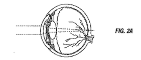
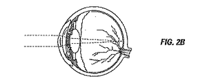
近年、屈折手術が開発されているので、近視、遠視、および乱視を外科的に処置するための多くの手術技術が、利用可能になっている。これらの手術技術のうち、Barraquerによって開発された第一の技術は、近視、遠視および乱視のためのケラトファキアの手順であった。図2Aおよび図2Bを参照すると、ケラトファキアは、「付加的」技術であることの利点を有しており、ケラトファキアでは患者から除去される組織はない。付加的物質は、屈折効果を生じる。従って、所望の効果が達成されないか、あるいは時間もしくは他の変化が、所望される除去または変更をなす場合、上記材料または物質は、除去または置換され得る。より一般的な技術であるLASIKは、組織を除去し、従って永久的に眼を変化させ、可逆的でも除去可能でもない。 In recent years, refractive surgery has been developed, and many surgical techniques are available to surgically treat myopia, hyperopia, and astigmatism. Of these surgical techniques, the first technique developed by Barraquer was the Keratophakia procedure for myopia, hyperopia and astigmatism. Referring to FIGS. 2A and 2B, keratofacia has the advantage of being an “additional” technology, in which no tissue is removed from the patient. The additional material produces a refractive effect. Thus, the material or substance can be removed or replaced if the desired effect is not achieved, or if time or other changes make the desired removal or modification. A more common technique, LASIK, removes tissue and thus permanently changes the eye and is neither reversible nor removable.
図3〜5を参照すると、ケラトファキア手術は、角膜支質および角膜上皮の弁状部を切る工程、上記弁状部を持ち上げる工程、およびなんらかの材料(有機材料または合成材料)のレンズを露出された床部上に配置する工程からなる。次いで、上記弁状部は、再配置されてそれ自身を塞ぐ。図4に示されるように、代表的に微小角膜切開刀が使用されて、上記弁状部を創り出す。上記微小角膜切開刀は、概して、大工のかんなまたは手術用皮膚採取器のように機能する刃を備えるデバイスであり、この微小角膜切開刀は、吸引環の向こう側の切断経路に動力化された運動の切断エレメントを同時に手動で押され得るか、または機械的に駆動し得る。この運動は、上記切断経路の方向に対して横行性である。 Referring to FIGS. 3-5, the keratofacia operation exposed the lens of the corneal stroma and corneal epithelium, lifting the valve, and a lens of some material (organic material or synthetic material). It consists of the process of arrange | positioning on a floor part. The valve is then repositioned to occlude itself. As shown in FIG. 4, a microkeratome is typically used to create the valve. The microkeratome is generally a device with a blade that functions like a carpenter's planer or surgical skin extractor, and the microkeratome is powered by a cutting path across the suction ring. The moving cutting elements can be manually pushed simultaneously or mechanically driven. This movement is transverse to the direction of the cutting path.
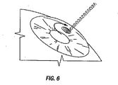
より近年、弁状部を作製するためのレーザーが開発されいる。これは、フェムト秒のレーザーであり、複数の型の弁状部を作製し得る。フェムト秒のレーザーを使用して作製される弁状部を示した図6を参照のこと。無限の種類の弁状部/床部形状を可能にするレーザーのソフトウェアを使用して、深さ、直径、ヒンジ位置および他の変数が設定され得る。 More recently, lasers have been developed for producing valve-like parts. This is a femtosecond laser and can produce multiple types of valves. See FIG. 6 which shows a valve made using a femtosecond laser. Depth, diameter, hinge position, and other variables can be set using laser software that allows an infinite variety of valve / floor shapes.
Jose Ignacio Barraquerは、Bogota(コロンビア)の彼の診療所で、50年前に層状屈折角膜手術の概念を生み出した。彼は、角膜支質組織の除去または組織の添加によって、涙液膜の前側の角膜表面が、影響され得、そして眼の屈折力を変更することを概念化した。彼は、彼の最初の結果を1949年に報告した。Barraquer博士が生み出した技術のための手術用語がケラトファキアであり、この用語は、ギリシャ語ルーツのkeras(角様角膜(horn−like−cornea))およびphakia(レンズ)に由来する。 Jose Ignacio Barraqueur created the concept of layered refractive corneal surgery 50 years ago at his clinic in Bogota (Colombia). He conceptualized that removal of corneal stroma tissue or addition of tissue can affect the anterior corneal surface of the tear film and alter the refractive power of the eye. He reported his first result in 1949. The surgical term for the technique created by Dr. Barraquer is keratofacia, which is derived from the Greek roots keras (horn-like-cornea) and phakia (lens).
Barraquer博士の初期の技術は、Paufiqueナイフまたは角膜解剖器具でフリーハンドの層状の解剖を行って、角膜層状ディスクを作製する工程からなった。次いで、彼はクリオレーズ(cryolathe)を使用してドナー由来のヒト支質から屈折レンズを成形した。 Dr. Barraquer's early technique consisted of making a corneal layered disc by freehand layered dissection with a Paufique knife or corneal dissection instrument. He then molded a refractive lens from a donor-derived human stroma using cryolathe.
Barraquer博士の画期的な業績および続くクリオレーズを使用して角膜ディスクを彫ることの研究によって、彼は、近代の近視性角膜曲率形成術、遠視性角膜曲率形成術、ケラトファキアおよびLASIKについての基礎を築いた。 With his breakthrough achievements by Dr. Barraquer and the study of carving corneal discs using subsequent Clioles, he laid the foundations for modern myopic corneal curvature, hyperopic corneal curvature, keratofacia and LASIK. Built.
しかし、Barraquer博士の初期技術に関して、いくつかの固有の欠点が存在した。これらの欠点としては、複雑な性質の手順および器具、誤りについての少ない余地、適切なレンズ材料および執刀医の急勾配な習熟曲線が挙げられる。さらに、この角膜切除術はフリーハンドによって行われるので、この切除は、安定した比率の通過、適切な吸引および良好なセントレーションに依存した。良好な角膜切除術が達成されなかった場合、境界面の傷、不規則に薄い角膜ディスクおよび最終的には不規則な乱視が経験され得る。 However, there were some inherent disadvantages with respect to Dr. Barraquer's early technology. These disadvantages include complex nature procedures and instruments, less room for error, suitable lens material and steep learning curve for the surgeon. Furthermore, since this keratotomy was performed freehand, this ablation relied on a steady rate of passage, proper aspiration and good centration. If good keratotomy is not achieved, interface wounds, irregularly thin corneal discs and eventually irregular astigmatism can be experienced.
ケラトファキアにおいて最良の結果を達成するための重要な工程は、微小角膜切開刀の制御された通過およびレンティクルのための適切な合成材料である。1980年後半に、Luis Ruizは、足で操作する自動化連動微小角膜切開刀を開発した。この微小角膜切開刀は、速度が制御されていることが原因で、より一貫した切断を提供し、上記角膜切除術は、非常に滑らかな表面を示した。その後、新規でよりよい角膜切開刀(例えば、Hansatomeおよびフェムト秒のレーザー)が、層状手術に対して正確かつ安全に添加されている。 An important step to achieve the best results in keratofacia is a suitable synthetic material for the controlled passage and lenticle of the microkeratome. In the late 1980s, Luis Ruiz developed an automated interlocking microkeratome that operates with the foot. The microkeratome provided a more consistent cut due to controlled speed, and the keratotomy showed a very smooth surface. Subsequently, new and better keratotomy tools (eg, Hansatome and femtosecond lasers) have been added accurately and safely to layered surgery.
研究者らは、ヒト組織に対する適切な置換物を見出す試みにおいて、多くの材料を使用している。ヒト組織は、利用の可能性が限定されており、凍結の間に成形されなければならない。例えば、特許文献1に議論される合成材料は、栄養素に対して多孔性であり得、非常に正確に多様な形状および力に作製され得る。 Researchers have used a number of materials in an attempt to find a suitable replacement for human tissue. Human tissue has limited availability and must be shaped during freezing. For example, the synthetic materials discussed in US Pat. No. 6,057,056 can be porous to nutrients and can be made very accurately in a variety of shapes and forces.
近代の角膜切開刀およびフェムト秒のレーザーを使用して、弁状部は、滑らかであるように作製されて不規則な乱視についての機会を正確に減少させ得る。近代的な材料は、角膜の拒絶反応または炎症を減少させ得、栄養素の透過を提供し得る。ケラトファキアレンティクルは、任意の組み合わせで遠視、近視および乱視を矯正するためになされ得る。 Using modern keratotomy and femtosecond lasers, the annulus can be made smooth to accurately reduce the chance of irregular astigmatism. Modern materials can reduce corneal rejection or inflammation and provide nutrient penetration. The keratofacia lenticle can be made to correct hyperopia, myopia and astigmatism in any combination.
ケラトファキアは、他の減じる技術(例えば、LASIK)を超えるいくつかの潜在的な利点を有する。LASIK手術は、角膜支質および角膜上皮の弁状部を切断する工程、上記弁状部を持ち上げる工程、およびエキシマーレーザーで露出された床部を再成形する工程からなる。次いで上記弁状部は、再配置されてそれ自身を塞ぐ。患者の角膜は、ケラトファキアにおいて屈折性質を変更されないので、上記操作は、より「可逆的」である。一旦レンズが配置されると、変化が必要とされる場合、上記弁状部は持ち上げられ得、そして古いレンズが除去された後に、新規のレンズが配置される。この操作は、上記手順に対して安全性を追加する。さらに、LASIKおよびケラトファキアが、多様な屈折の誤りのために組み合わせられ得る。 Keratophakia has several potential advantages over other diminishing technologies (eg, LASIK). LASIK surgery consists of a step of cutting the corneal stroma and the valvular portion of the corneal epithelium, a step of lifting the valve-like portion, and a step of reshaping the floor exposed by the excimer laser. The valve then repositions and closes itself. The operation is more “reversible” because the patient's cornea is not altered in refractive properties in keratofacia. Once the lens is placed, if changes are needed, the valve can be lifted and a new lens is placed after the old lens is removed. This operation adds safety to the above procedure. Furthermore, LASIK and keratophakia can be combined due to various refraction errors.
ケラトファキアに関する新規の業績は、不規則な乱視および栄養分透過の問題が広く解決されたことを示している。現在、注目するべきは、レンティクルの重要なセントレーション、および配置した後に移動しないような方法で、上記レンティクルを配置する必要性である。上記レンズは、正確に中心に置かれなければならず、次いでそのセントレーションは、上記弁状部をもとに戻す間維持されなければならない。さらに、上記レンズは、困難であり得る手術の後に、その所望の部位で保持されなければならない。 New work on keratofacia shows that the problem of irregular astigmatism and nutrient penetration has been widely solved. At present, it should be noted that there is an important centration of the lenticle and the need to place the lenticle in such a way that it does not move after placement. The lens must be precisely centered and then its centration must be maintained while the valve is replaced. Furthermore, the lens must be held at its desired site after surgery, which can be difficult.
さらに、乱視を解消するためにケラトファキアを使用することは、そのレンズが中心に保持されなければならないだけでなく、回転力を与えられても回転してもならないことを意味する。 Furthermore, using a keratophakia to eliminate astigmatism means that the lens must not only be held in the center, but must also be rotated when given a rotational force.
手術方法は、角膜に対する最小限の操作によって、フェムト秒のレーザーを使用して素早く再現的に弁状部を形造るために提案され、上記方法は、弁状部を持ち上げる工程、レンズを移植する工程、およびレンズの上に弁状部を戻す工程を包含する。当業者は、本明細書中の開示を読んだ後に、上記弁状部が無限に多様な形状に作製されてセントレーションおよびレンズの安定性を増強し得ることを理解する。
(発明の要旨)
本発明は、層状手術における必要性を満たすように設計され、そして微小角膜切開刀またはフェムト秒のレーザー系を使用してケラトファキア弁状部を作製するための、新規かつ改善された方法に関する。さらに、本発明は、角膜を切断して、例えば、ボーマン膜の下または角膜支質内に角膜組織のちょうつがいの弁状部を作製するように設計される。適切に選択されたレンズは、露出された角膜組織上に移植され、次いで上記弁状部は、レンズの上に配置される。
(Summary of the Invention)
The present invention relates to a new and improved method for creating a keratophakic annulus using a microkeratome or femtosecond laser system designed to meet the needs in layered surgery. Furthermore, the present invention is designed to cut the cornea to create, for example, a hinged flap of corneal tissue under the Bowman's membrane or in the corneal stroma. A properly selected lens is implanted over the exposed corneal tissue, and then the valve is placed over the lens.
1つの実施形態において、上記配置は、遠視(hyperopia)または遠視(farsightedness)を解消するために設計されたレンズを配置するための、弁状部についての設計を包含することを意味する。遠視のためのケラトファキアにおいて、環状レンズ、凸レンズまたは縁よりも中央部が厚いレンズが、床部中に配置される。本発明は、弁状部および床部の設計を記載し、その結果、「くぼみ(Recess)」構造または「プラットフォーム(Platform)」構造または「レール(Rail)」構造または「溝(Gutter)」構造もしくは「楕円(Oval)」構造もしくは「ポスト(Post)」構造もしくは「タブ(Tab)」構造が作製されて、手術の間に簡単、迅速かつ正確なセントレーション、弁状部を置換する間の安定性および手術の後のレンズの安定性を可能にする。 In one embodiment, the above arrangement is meant to encompass a design for the valve to place a lens designed to eliminate hyperopia or farsightedness. In Keratophakia for hyperopia, an annular lens, a convex lens or a lens that is thicker at the center than the edge is placed in the floor. The present invention describes a valve and floor design, so that a “Recess” structure or a “Platform” structure or a “Rail” structure or a “Gutter” structure. Or “Oval” or “Post” or “Tab” structures are created to allow simple, quick and accurate centration during surgery, during valve replacement Enables stability and stability of the lens after surgery.
本発明の1つの実施形態において、角膜移植物を移植する方法が存在する。上記方法は、角膜の外面の部分を分離して、それによって角膜弁状部および角膜床部を形成する工程を包含する。上記角膜弁状部は、前面および後面を有する。上記角膜床部は、成形された前面を有する。角膜移植物のようなレンズが、上記角膜床部上に移植または配置される。代表的には、上記レンズは前面および後面を有する。多くの型のレンズが本方法での使用のために適切であることは、当業者には公知である。分離された角膜の部分は、置換される。 In one embodiment of the invention, there is a method of implanting a corneal implant. The method includes the steps of separating a portion of the outer surface of the cornea, thereby forming a corneal flap and a corneal bed. The corneal flap has a front surface and a rear surface. The corneal floor has a molded front surface. A lens, such as a corneal implant, is implanted or placed on the corneal bed. Typically, the lens has a front surface and a rear surface. It is known to those skilled in the art that many types of lenses are suitable for use in the present method. The separated portion of the cornea is replaced.
本方法に関して、いくつかの重要な局面が存在する。本発明の1つの局面において、上記角膜床部は、手術の間、所定の位置にレンズを維持するような構造で成形される。 There are several important aspects of the method. In one aspect of the invention, the corneal floor is shaped with a structure that maintains the lens in place during surgery.
本発明の1つの局面において、上記角膜床部は、手術の間および/または手術の後にレンズのセントレーションに役立つように成形される。 In one aspect of the invention, the corneal bed is shaped to aid lens centration during and / or after surgery.
本発明の1つの局面において、上記角膜床部は、上記レンズの後面の形状に適合するように成形される。 In one aspect of the present invention, the corneal floor is shaped to match the shape of the rear surface of the lens.
本発明の1つの局面において、上記レンズの移植および上記角膜弁状部の置換は、遠視、近視、または乱視を矯正する。 In one aspect of the invention, the implantation of the lens and the replacement of the corneal flap corrects hyperopia, myopia, or astigmatism.
別の局面において、上記角膜床部および上記角膜弁状部は、それらが互いの鏡像を形成するように成形または構成される。以下の形状は、上記レンズのセントレーションに役立つために有用であるが、網羅的な列挙であることは意図されない。このような形状としては、くぼんだ構造、プラットフォーム構造、溝構造、レール構造、楕円構造、タブ構造、またはポスト構造を有する角膜床部の前面(anteriot surface)が挙げられる。 In another aspect, the corneal floor and the corneal flap are shaped or configured such that they form a mirror image of each other. The following shapes are useful to aid in the centration of the lens, but are not intended to be an exhaustive list. Such a shape includes an anterior surface of the corneal floor having a recessed structure, a platform structure, a groove structure, a rail structure, an elliptical structure, a tab structure, or a post structure.
本発明の1つの局面において、フェムト秒のレーザーが利用されて、上記レンズの配置を助けるための幾何学的に特異的な弁状部を作製する。現在、視線を越えるセントレーションは、ケラトファキアでは困難である。一旦、上記角膜弁状部が確実に作製されると、患者は定着させることができない。従って、異なる光の反射が依存されなければならない。機械的角膜切開刀は、完全に中心に配置された弁状部を作製しないかもしれない。フェムト秒のレーザーを使用して上記角膜弁状部を作製することは、上記弁状部が瞳孔の上で直接中心に配置されることを可能にし、屈折セントレーションのための好ましい方法である。この弁状部は中央に配置されているので、その形状はまた中心に配置され得る。故に、上記レンズは、中心に配置された形状で配置され得、所望の位置に存在する。 In one aspect of the invention, a femtosecond laser is utilized to create a geometrically specific valve to aid in the placement of the lens. At present, centration beyond the line of sight is difficult in Keratofakia. Once the corneal flap is reliably created, the patient cannot be established. Therefore, different light reflections must be relied upon. A mechanical keratome may not create a perfectly centered valve. Fabricating the corneal flap using a femtosecond laser allows the valve to be centered directly on the pupil and is a preferred method for refractive centration. Since the valve is centrally located, its shape can also be centrally located. Therefore, the lens can be arranged in a centrally arranged shape and exists at a desired position.
本発明の別の局面は、上記弁状部を置換する間、上記レンズの安定化に役立つ形状を作製することである。ケラトファキア手術において、上記弁状部の置換は、上記レンズを取り除き得、境界面を洗浄する。最近の方法におけるレンズは、このことから保護されている。 Another aspect of the present invention is to create a shape that helps stabilize the lens while replacing the valve. In keratophia surgery, the replacement of the valve can remove the lens and clean the interface. The lenses in modern methods are protected from this.
本発明の別の局面は、上記レンズに長期間の安定性を与えることである。近代のケラトファキアにおいて、上記レンズは、手術後に時々その位置を変えることが注目されている。このことは、過剰な流動性または他の因子に起因し得る。しかし、本明細書中に記載される弁状部および角膜床部の作製は、手術の間および手術の後に長期間の安定性を提供する。 Another aspect of the present invention is to provide long-term stability to the lens. In modern keratofakia, it is noted that the lens sometimes changes its position after surgery. This can be due to excessive fluidity or other factors. However, the creation of the valve and corneal bed described herein provides long-term stability during and after surgery.
本発明の別の局面は、レンズを配置して回転力を与えられることも回転することも減少させるかまたは妨げる能力である。楕円形状を使用することによって、長方形形状、他の形状またはタブ形状が、レンズを所定の位置に維持する。 Another aspect of the present invention is the ability to place or reduce the rotation of the lens to provide or rotate. By using an elliptical shape, a rectangular shape, other shape or tab shape maintains the lens in place.
上記のものは、以下の本発明の詳細な説明がよりよく理解され得るために、本発明の特徴および技術的な利点をかなり広範に概説している。本発明の特許請求の範囲の主題を形成する本発明のさらなる特徴および利点は、以下に記載される。開示される概念および特定の実施形態は、本発明の同一の目的を実行するために他の構造を改変または設計するための基礎として、容易に利用され得ることが認識されるべきである。そのような等価な構造は、添付される特許請求の範囲に示される本発明から逸脱しないこともまた、理解されるべきである。本発明の特徴であると考えられる新規の特性は、その編成と操作の方法との両方に関してであり、さらなる物体および利点と一緒に、添付の図と関連して考慮される場合、以下の説明からよりよく理解される。しかし、それぞれの図は、説明および記載のみの目的のために提供され、本発明の定義を限定するものとしては意図されないことは、はっきりと理解されるべきである。 The foregoing has outlined rather broadly the features and technical advantages of the present invention in order that the detailed description of the invention that follows may be better understood. Additional features and advantages of the invention will be described hereinafter that form the subject of the claims of the invention. It should be appreciated that the disclosed concepts and specific embodiments can be readily utilized as a basis for modifying or designing other structures for carrying out the same purposes of the present invention. It should also be understood that such equivalent constructions do not depart from the invention as set forth in the appended claims. The novel features considered characteristic of the present invention are both in terms of its organization and method of operation, together with further objects and advantages, when considered in conjunction with the accompanying figures, the following description Better understood. It should be expressly understood, however, that each figure is provided for purposes of illustration and description only and is not intended to limit the definition of the invention.
本発明のよりよい理解は、添付された図面と合わせて考慮される場合、以下に示される例示的な実施形態の詳細な説明から得られ得る。 A better understanding of the present invention can be obtained from the detailed description of exemplary embodiments set forth below when considered in conjunction with the accompanying drawings.
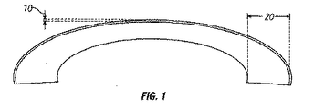
図1は、角膜の略図である。瞳孔の後ろに位置する眼の角膜または透明なウインドウ(window)、およびレンズは、上記眼の後方で網膜上に見られる物体からの光線に焦点を合わせるために役に立つ。上記角膜は、5つの層から構成される。第一の層は、5個の細胞の厚さである上皮で、通常およそ60ミクロンの厚さである(10−10)。ボーマン膜と呼ばれる薄い膜が、上皮の下に敷かれる。上記角膜の塊は支質と呼ばれ、約480ミクロンの厚さである(20)。第四の層は、デスメー膜と呼ばれる、別のより強いが非常に薄い膜である。最後の層は、内皮であり、1個の細胞の厚さしかない。ボーマン膜、デスメー膜、および上記内皮は、全体の角膜の厚さに顕著には寄与しない。上記角膜の全体の厚さは、平均するとおよそ540ミクロンである。一旦、角膜およびレンズが、網膜上で光線に焦点が合うと、上記網膜は、視神経を介して脳に見られる物体の像を伝達する。通常、これらの光線は、上記網膜上に正確に焦点を合わされ、離れた物体が明確かつはっきりと見られることを可能にする。しかし、上記角膜表面が正常な形状からずれると、可視プロセスにおいて屈折の誤りが生じ、その結果、眼は、上記網膜上の離れた物体の像に焦点を合わせることができなくなる。遠視(hyperopia)または「遠視(farsightedness)」は、屈折の誤りであり、遠視では、実線によって示されるように、離れた物体からの光線は、網膜の後ろの点で焦点が合う。近視(myopia)または「近視(nearsightedness)は、屈折の誤りであり、近視では、実線によって示されるように、離れた物体からの光線は、網膜の前で焦点が合い、この光線が網膜に到達する場合、光線は分岐し、円の拡散を形成してそれによってぼやけた像を形成する。 FIG. 1 is a schematic illustration of the cornea. The eye cornea or transparent window behind the pupil, and the lens, are useful for focusing light rays from objects seen on the retina behind the eye. The cornea is composed of five layers. The first layer is an epithelium that is 5 cells thick and is usually approximately 60 microns thick (10-10). A thin membrane called Bowman's membrane is laid under the epithelium. The corneal mass is called the stroma and is approximately 480 microns thick (20). The fourth layer is another stronger but very thin membrane called the desmede membrane. The last layer is the endothelium, which is only one cell thick. Bowman's membrane, Descemet's membrane, and the endothelium do not contribute significantly to the overall corneal thickness. The overall thickness of the cornea is approximately 540 microns on average. Once the cornea and lens are focused on the retina, the retina transmits an image of the object seen in the brain via the optic nerve. Usually these rays are precisely focused on the retina, allowing distant objects to be seen clearly and clearly. However, if the corneal surface deviates from its normal shape, a refraction error occurs in the visible process, so that the eye cannot focus on the image of a distant object on the retina. Hyperopia or “farsightedness” is an error in refraction, in which far rays from a distant object are focused at a point behind the retina, as indicated by the solid line. Myopia or “nearsightedness” is an error in refraction, and in myopia, as indicated by the solid line, light rays from a distant object are in focus in front of the retina, and these rays reach the retina. When doing so, the rays diverge and form a circular diffusion, thereby creating a blurred image.
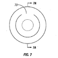
ここで図7を参照すると、上記くぼんだ構造は、上記弁状部を作製する間、上記角膜の床部に成形された切断部分である。上記角膜弁状部70は、前面71および後面72を有する。上記角膜の露出された表面は、角膜床部75と称される。上記露出された角膜床部は、前面76を有する。上記くぼみは、任意の所望の深さまたは直径で、乱視を解消するための任意の位置に作製される。レンズ79は、くぼみ77中に配置され、上記弁状部が再配置される。上記くぼみの鏡像が弁状部の裏側に作製されるので、屈折効果は保存される。示される特定の実施形態の例において、上記角膜弁状部および上記角膜床部は、互いの鏡像である。上記角膜弁状部は、上記角膜床部のウェルに適合する隆起78を有するように成形される。レンズまたは角膜移植物74は、上記くぼみ中に配置され、そして上記角膜弁状部は戻される。上記角膜弁状部の隆起は、上記移植物と接触する状態で置かれる。このことは、角膜73を急勾配にする効果を有する。示される上面図は、ちょうつがい79を有する角膜弁状部を示す。
Referring now to FIG. 7, the recessed structure is a cut portion formed in the corneal floor during the production of the valve-like portion. The
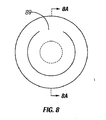
ここで図8を参照すると、上記プラットフォーム構造は、任意の位置、形状または寸法で上記角膜床部上に作製された隆起した形状である。角膜弁状部80は、前面81および後面82を有する。上記角膜の露出された表面は、角膜床部85と称される。上記露出された角膜床部は、前面86を有する。レンズ84は、プラットフォーム87上に配置され、そして上記弁状部は再配置される。上記プラットフォームの鏡像が、弁状部の裏面に作製されるので、屈折効果は保存される。示される特定の実施形態の例において、上記角膜弁状部および上記角膜床部は、互いに鏡像である。上記角膜弁状部は、上記弁状部が角膜床部のプラットフォームと適合するくぼみ88を有するように成形される。レンズまたは角膜移植物は、上記プラットフォーム上に配置され、そして上記角膜弁状部は戻される。上記角膜弁状部のくぼみは、上記移植物と接触する状態で置かれる。このことは、角膜83を急勾配にする効果を有する。示される上面図は、ちょうつがい89を有する角膜弁状部を示す。
Referring now to FIG. 8, the platform structure is a raised shape created on the corneal floor at any location, shape or size. The
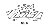
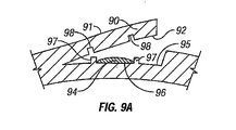
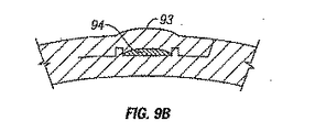
ここで図9を参照すると、上記レール構造は、任意の位置、形状、または寸法で上記床部上に作製された隆起した環状バンドまたはフェンスである。角膜弁状部90は、前面91および後面92を有する。上記角膜の露出された表面は、角膜床部95と称される。上記露出された角膜床部は、前面96を有する。上記レンズは、レール97の内部に配置され、そして上記弁状部は再配置される。上記レールの鏡像が、弁状部の裏面に作製されるので、屈折効果は保存される。示される特定の実施形態の例において、上記角膜弁状部および上記角膜床部は、互いに鏡像である。上記角膜弁状部は、上記弁状部が角膜床部の隆起した環状バンドまたはフェンスと適合する溝またはチャネル98を有するように成形される。レンズまたは角膜移植物94は、上記フェンスまたはレールの内部に配置され、そして上記角膜弁状部は戻される。上記溝またはチャネルとの間の角膜弁状部の表面は、上記移植物と接触する状態で置かれる。このことは、角膜93を急勾配にする効果を有する。示される上面図は、ちょうつがい99を有する角膜弁状部を示す。
Referring now to FIG. 9, the rail structure is a raised annular band or fence made on the floor at any location, shape, or size. The
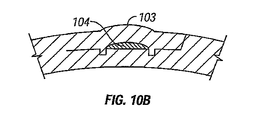
ここで図10を参照すると、上記溝構造は、任意の位置、形状、または寸法で上記床部上に作製された低くなったチャネルである。角膜弁状部100は、前面101および後面102を有する。上記角膜の露出された表面は、角膜床部105と称される。上記露出された角膜床部は、前面106を有する。レンズ104は、溝またはチャネル107の内部の中央に配置され、そして上記弁状部は再配置される。上記溝の鏡像が、弁状部の後面に作製されるので、屈折効果は保存される。示される特定の実施形態の例において、上記角膜弁状部および上記角膜床部は、互いに鏡像である。上記角膜弁状部は、上記弁状部が角膜床部の溝またはチャネルと適合するフェンスまたはレール108を有するように成形される。レンズまたは角膜移植物は、上記角膜床部の溝またはチャネルの間の表面に配置され、そして上記角膜弁状部は戻される。上記フェンスまたはレールの間の角膜弁状部の表面は、上記移植物と接触する状態で置かれる。このことは、角膜103を急勾配にする効果を有する。示される上面図は、ちょうつがい109を有する角膜弁状部を示す。
Referring now to FIG. 10, the groove structure is a lowered channel made on the floor at any location, shape, or size. The
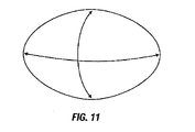
ケラトファキアはまた、乱視を矯正するために使用される。図11は、乱視の幾何学の説明である。乱視を矯正するために、1つの軸において他の軸よりも急勾配であるか、または平らであるレンズが、必要とされる。このレンズ124は、楕円に成形され得る。図12および図12Aを参照すると、このようなレンズにおいて、上記形状の組み合わせは、楕円様式に作製され得、セントレーション性を追加し、上記弁状部の置換の間にセントレーションを維持し、手術後の安定性を助けるが、乱視のレンティクルが回転力を与えられるか、または回転することから保護する。上記角膜弁状部120は、前面121および後面122を有する。上記角膜の露出された表面は、角膜床部125と称される。上記露出された角膜床部は、前面126を有する。特定のレンズがより高いオーダーの異常な矯正を有するように作製される場合、これらの技術は、そのレンズをさらに中心に配置するために使用され得る。
Keratophakia is also used to correct astigmatism. FIG. 11 is an explanation of the geometry of astigmatism. To correct astigmatism, a lens that is steeper or flatter in one axis than the other is needed. The
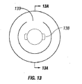
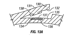
図13および図13Aを参照すると、上記レンズの回転を妨げることに加えて、さらなる形状のタブが、任意の寸法、大きさまたは位置で作製され得る。1つの例において、上記タブは、示されるタブ形状138を有するが、これに限定されない。角膜弁状部130は、前面131および後面132を有する。上記角膜の露出された表面は、角膜床部135と称される。この露出された角膜床部は、前面136を有する。
Referring to FIGS. 13 and 13A, in addition to preventing rotation of the lens, additional shaped tabs can be made in any size, size or position. In one example, the tab has the
ケラトファキアはまた、近視を矯正するために使用され得る。近視において、上記レンズは、周辺領域と比較して中心領域においてより薄いか、または存在さえしない。図14、図14Aを参照すると、中心に開口部を有するレンズ144は、ポスト147によって安定化され得る。角膜弁状部140は、前面141および後面142を有する。上記角膜の露出された表面は、角膜床部145と称される。この露出された角膜床部は、前面146を有する。上記角膜床部は、上記弁状部の前面から伸長するポストを有する。開口部を有するレンズは、上記ポストの上に配置される。上記ポストは、上記角膜弁状部において対応するスロット148を有する。示される上面図は、ちょうつがい149を有する角膜弁状部を示す。中心部においてより薄い部分を有するレンズは、平坦化効果(flattening effect)143を有する。
Keratophakia can also be used to correct myopia. In myopia, the lens is thinner or not even present in the central region compared to the peripheral region. Referring to FIGS. 14 and 14A, a
本発明に包含されるものは、任意の寸法の任意の弁状部または上記の基本的な形状の組み合わせを形造る能力である。本発明およびその利点は詳細に記載されているが、種々の変化、置換および変更が、添付される特許請求の範囲によって規定される本発明から逸脱することなく、本明細書中でなされ得ることが理解される。さらに、本発明の適用の範囲は、本明細書中に記載されるプロセス、機械、製品、組成物、手段、方法、および工程の特定の実施形態に限定されることは意図されない。本発明に存在するか、または後に開発されて、本明細書中に記載される対応する実施形態と実質的に同じ機能を実行するか、または実質的に同じ結果を達成されるのプロセス、機械、製品、組成物、手段、方法、または工程が利用され得ることが開示から理解される。従って、添付される特許請求の範囲は、このようなのプロセス、機械、製品、組成物、手段、方法、または工程の範囲内に含まれることが意図される。 Included in the present invention is the ability to shape any valve or any combination of the above basic shapes of any size. Although the invention and its advantages have been described in detail, various changes, substitutions and alterations can be made herein without departing from the invention as defined by the appended claims. Is understood. Furthermore, the scope of application of the present invention is not intended to be limited to the specific embodiments of the processes, machines, products, compositions, means, methods, and steps described herein. Process, machine present in the present invention or later developed to perform substantially the same function or achieve substantially the same result as the corresponding embodiments described herein It is understood from the disclosure that any product, composition, means, method or process can be utilized. Accordingly, the appended claims are intended to be included within the scope of such processes, machines, products, compositions, means, methods, or steps.
さらに、記載される実施形態は、本発明を実施するための最良の様式を説明することをさらに意図し、他の当業者が、このような実施形態または他の実施形態において、本発明の特定の適用または使用によって必要とされる種々の改変とともに本発明を利用し得ることもさらに意図する。添付される特許請求の範囲が先行技術によって可能な程度までの代替的な実施形態を包含するように解釈されることが意図される。 Furthermore, the described embodiments are further intended to illustrate the best mode for carrying out the invention, and other persons skilled in the art will be able to identify the invention in such or other embodiments. It is further contemplated that the present invention may be utilized with various modifications as required by the application or use of. It is intended that the appended claims be construed to include alternative embodiments to the extent possible by the prior art.
Claims (20)
角膜の外側の部分を分離して、それによって角膜弁状部および角膜床部を形成する工程であって、該角膜弁状部は、前面および後面を有し、該角膜床部は、成形された前面を有する、工程;
該角膜床部上にレンズを移植する工程であって、該レンズは、前面および後面を有する、工程;および
分離された角膜の部分をもとに戻す工程、
を包含する、方法。 A method of transplanting a corneal implant, the method comprising:
Separating the outer portion of the cornea, thereby forming a corneal flap and a corneal floor, the corneal flap having a front surface and a back surface, the corneal floor portion being molded Having a front surface;
Implanting a lens on the corneal floor, the lens having an anterior surface and a posterior surface; and reversing the separated corneal portion;
Including the method.
Applications Claiming Priority (2)
| Application Number | Priority Date | Filing Date | Title |
|---|---|---|---|
| US49679703P | 2003-08-21 | 2003-08-21 | |
| PCT/US2004/027274 WO2005020792A2 (en) | 2003-08-21 | 2004-08-23 | Method for keratophakia surgery |
Publications (2)
| Publication Number | Publication Date |
|---|---|
| JP2007503225A true JP2007503225A (en) | 2007-02-22 |
| JP2007503225A5 JP2007503225A5 (en) | 2007-10-04 |
Family
ID=34272517
Family Applications (1)
| Application Number | Title | Priority Date | Filing Date |
|---|---|---|---|
| JP2006524104A Pending JP2007503225A (en) | 2003-08-21 | 2004-08-23 | Method for keratofacia surgery |
Country Status (5)
| Country | Link |
|---|---|
| US (1) | US20050178394A1 (en) |
| JP (1) | JP2007503225A (en) |
| AU (1) | AU2004268582A1 (en) |
| CA (1) | CA2535052A1 (en) |
| WO (1) | WO2005020792A2 (en) |
Families Citing this family (16)
| Publication number | Priority date | Publication date | Assignee | Title |
|---|---|---|---|---|
| US8668735B2 (en) | 2000-09-12 | 2014-03-11 | Revision Optics, Inc. | Corneal implant storage and delivery devices |
| AU2001289038B2 (en) | 2000-09-12 | 2006-05-18 | Revision Optics, Inc. | System for packaging and handling an implant and method of use |
| US7776086B2 (en) | 2004-04-30 | 2010-08-17 | Revision Optics, Inc. | Aspherical corneal implant |
| US8057541B2 (en) * | 2006-02-24 | 2011-11-15 | Revision Optics, Inc. | Method of using small diameter intracorneal inlays to treat visual impairment |
| US10835371B2 (en) | 2004-04-30 | 2020-11-17 | Rvo 2.0, Inc. | Small diameter corneal inlay methods |
| US10555805B2 (en) * | 2006-02-24 | 2020-02-11 | Rvo 2.0, Inc. | Anterior corneal shapes and methods of providing the shapes |
| US7947447B2 (en) | 2007-01-16 | 2011-05-24 | Somalogic, Inc. | Method for generating aptamers with improved off-rates |
| US9271828B2 (en) | 2007-03-28 | 2016-03-01 | Revision Optics, Inc. | Corneal implant retaining devices and methods of use |
| US8162953B2 (en) | 2007-03-28 | 2012-04-24 | Revision Optics, Inc. | Insertion system for corneal implants |
| US9549848B2 (en) | 2007-03-28 | 2017-01-24 | Revision Optics, Inc. | Corneal implant inserters and methods of use |
| US9539143B2 (en) | 2008-04-04 | 2017-01-10 | Revision Optics, Inc. | Methods of correcting vision |
| JP2011516180A (en) | 2008-04-04 | 2011-05-26 | レヴィジオン・オプティックス・インコーポレーテッド | Corneal inlay design and method for correcting vision |
| EP2477587B1 (en) * | 2009-09-18 | 2017-01-11 | AMO Development, LLC | Registration of corneal flap with ophthalmic measurement and/or treatment data for lasik and other procedures |
| US8469948B2 (en) | 2010-08-23 | 2013-06-25 | Revision Optics, Inc. | Methods and devices for forming corneal channels |
| US9345569B2 (en) | 2011-10-21 | 2016-05-24 | Revision Optics, Inc. | Corneal implant storage and delivery devices |
| WO2016144404A1 (en) | 2015-03-12 | 2016-09-15 | Revision Optics, Inc. | Methods of correcting vision |
Citations (7)
| Publication number | Priority date | Publication date | Assignee | Title |
|---|---|---|---|---|
| JPH03173560A (en) * | 1989-11-22 | 1991-07-26 | Allergan Inc | Corneal lens transplant device |
| US6197019B1 (en) * | 1994-04-25 | 2001-03-06 | Gholam A. Peyman | Universal implant blank for modifying corneal curvature and methods of modifying corneal curvature therewith |
| JP2001276112A (en) * | 2000-03-27 | 2001-10-09 | Intorareizu Corp | Apparatus for changing shape of optically changeable material under flap |
| JP2003052737A (en) * | 2001-07-27 | 2003-02-25 | 20 10 Perfect Vision Optische Geraete Gmbh | Laser beam emission system provided with multiple focal points |
| JP2003508135A (en) * | 1999-08-27 | 2003-03-04 | アナメッド インク. | Corneal implant and manufacturing method |
| JP2003199782A (en) * | 2001-12-28 | 2003-07-15 | Nidek Co Ltd | Cornea operation device |
| JP2003210514A (en) * | 2002-01-25 | 2003-07-29 | Nidek Co Ltd | Ophthalmic operating equipment |
Family Cites Families (76)
| Publication number | Priority date | Publication date | Assignee | Title |
|---|---|---|---|---|
| US3743337A (en) * | 1971-07-26 | 1973-07-03 | E Crary | Contact lens inserter |
| US4065816A (en) * | 1975-05-22 | 1978-01-03 | Philip Nicholas Sawyer | Surgical method of using a sterile packaged prosthesis |
| US4326306A (en) * | 1980-12-16 | 1982-04-27 | Lynell Medical Technology, Inc. | Intraocular lens and manipulating tool therefor |
| US4671276A (en) * | 1982-01-04 | 1987-06-09 | Kera Associates | Apparatus for corneal curvature adjustment |
| US4766895A (en) * | 1982-01-04 | 1988-08-30 | Kera Corneal Devices, Inc. | Apparatus for corneal curvature adjustment |
| US4702244A (en) * | 1982-02-05 | 1987-10-27 | Staar Surgical Company | Surgical device for implantation of a deformable intraocular lens |
| US4504982A (en) * | 1982-08-05 | 1985-03-19 | Optical Radiation Corporation | Aspheric intraocular lens |
| US4580882A (en) * | 1983-04-21 | 1986-04-08 | Benjamin Nuchman | Continuously variable contact lens |
| US4565198A (en) * | 1983-12-27 | 1986-01-21 | Barnes-Hind, Inc. | Method for altering the curvature of the cornea |
| US4586929A (en) * | 1984-04-06 | 1986-05-06 | Binder Perry S | Hydrogel keratoprosthesis |
| DE3433581C2 (en) * | 1984-09-13 | 1986-08-07 | Fa. Carl Zeiss, 7920 Heidenheim | Device for laminating, refractive corneal surgery |
| US6264648B1 (en) * | 1985-07-29 | 2001-07-24 | Bausch & Lomb Incorporated | Corneal curvature modification via internal ablation |
| US4726367A (en) * | 1985-08-19 | 1988-02-23 | Shoemaker David W | Surgical instrument for implanting an intraocular lens |
| US5030230A (en) * | 1986-05-16 | 1991-07-09 | Great Plains Eye Clinic, Ltd. | Corneal implant |
| US4772283A (en) * | 1986-05-16 | 1988-09-20 | White Thomas C | Corneal implant |
| CS263203B1 (en) * | 1986-07-22 | 1989-04-14 | Sulc Jiri | Soft intraocular lenses |
| US5019084A (en) * | 1986-08-06 | 1991-05-28 | Minnesota Mining And Manufacturing Company | Corneal holder |
| US4697697A (en) * | 1986-08-18 | 1987-10-06 | Coopervision, Inc. | Method and apparatus for packaging an intraocular lens |
| US4676792A (en) * | 1986-08-26 | 1987-06-30 | Donald Praeger | Method and artificial intraocular lens device for the phakic treatment of myopia |
| US4842599A (en) * | 1986-10-28 | 1989-06-27 | Ann M. Bronstein | Prosthetic cornea and method of implantation therefor |
| US4897981A (en) * | 1986-12-24 | 1990-02-06 | Alcon Laboratories, Inc. | Method of packaging intraocular lenses and contact lenses |
| US4840175A (en) * | 1986-12-24 | 1989-06-20 | Peyman Gholam A | Method for modifying corneal curvature |
| US4923467A (en) * | 1988-03-02 | 1990-05-08 | Thompson Keith P | Apparatus and process for application and adjustable reprofiling of synthetic lenticules for vision correction |
| US4860885A (en) * | 1988-04-29 | 1989-08-29 | Allergan, Inc. | Lens storage system |
| US5211660A (en) * | 1988-05-02 | 1993-05-18 | University Of South Florida | Method for performing epikeratophakia by electrofusion |
| US5785674A (en) * | 1988-10-07 | 1998-07-28 | Mateen; Ahmed Abdul | Device and method for treating glaucoma |
| US4976719A (en) * | 1988-11-21 | 1990-12-11 | Siepser Steven B | Device used to change corneal curvature |
| US4911715A (en) * | 1989-06-05 | 1990-03-27 | Kelman Charles D | Overlapping two piece intraocular lens |
| US5063942A (en) * | 1989-12-14 | 1991-11-12 | Corneal Contouring, Inc. | Method for surgically re-profiling the cornea |
| US5591185A (en) * | 1989-12-14 | 1997-01-07 | Corneal Contouring Development L.L.C. | Method and apparatus for reprofiling or smoothing the anterior or stromal cornea by scraping |
| US5318044A (en) * | 1989-12-14 | 1994-06-07 | Corneal Contouring, Inc. | Method and apparatus for re-profiling the cornea to correct for hyperopia |
| US5312413A (en) * | 1991-07-17 | 1994-05-17 | Eaton Alexander M | Instrumentation for ophthalmic surgery and method of using the same |
| US6325792B1 (en) * | 1991-11-06 | 2001-12-04 | Casimir A. Swinger | Ophthalmic surgical laser and method |
| AU650156B2 (en) * | 1992-08-05 | 1994-06-09 | Lions Eye Institute Limited | Keratoprosthesis and method of producing the same |
| US5318046A (en) * | 1992-09-23 | 1994-06-07 | Rozakis George W | Method for corneal reprofiling |
| WO1995013766A1 (en) * | 1993-11-18 | 1995-05-26 | Allergan, Inc. | Deformable lens insertion apparatus |
| US5630810A (en) * | 1994-05-06 | 1997-05-20 | Machat; Jeffery J. | Method of ophthalmological surgery |
| US6302877B1 (en) * | 1994-06-29 | 2001-10-16 | Luis Antonio Ruiz | Apparatus and method for performing presbyopia corrective surgery |
| US5755785A (en) * | 1994-08-12 | 1998-05-26 | The University Of South Florida | Sutureless corneal transplantation method |
| US6110166A (en) * | 1995-03-20 | 2000-08-29 | Escalon Medical Corporation | Method for corneal laser surgery |
| US5722971A (en) * | 1995-10-20 | 1998-03-03 | Peyman; Gholam A. | Intrastromal corneal modification |
| US6551307B2 (en) * | 2001-03-23 | 2003-04-22 | Gholam A. Peyman | Vision correction using intrastromal pocket and flap |
| US5919185A (en) * | 1997-04-25 | 1999-07-06 | Peyman; Gholam A. | Universal implant blank for modifying corneal curvature and methods of modifying corneal curvature therewith |
| US6280470B1 (en) * | 1995-10-20 | 2001-08-28 | Gholam A. Peyman | Intrastromal corneal modification |
| US20050143717A1 (en) * | 2001-04-27 | 2005-06-30 | Peyman Gholam A. | Method of treatment of refractive errors using subepithelial or intrastromal corneal inlay with bonding coating |
| US6221067B1 (en) * | 1995-10-20 | 2001-04-24 | Gholam A. Peyman | Corneal modification via implantation |
| US5964748A (en) * | 1995-10-20 | 1999-10-12 | Peyman; Gholam A. | Intrastromal corneal modification |
| US6203538B1 (en) * | 1995-11-03 | 2001-03-20 | Gholam A. Peyman | Intrastromal corneal modification |
| US5817115A (en) * | 1995-12-04 | 1998-10-06 | Chiron Vision Corporation | Apparatus for resecting corneal tissue |
| US5728155A (en) * | 1996-01-22 | 1998-03-17 | Quantum Solutions, Inc. | Adjustable intraocular lens |
| US5695513A (en) * | 1996-03-01 | 1997-12-09 | Metagen, Llc | Flexible cutting tool and methods for its use |
| US5733334A (en) * | 1996-12-09 | 1998-03-31 | Microoptix | Method and apparatus for adjusting corneal curvature |
| US5855604A (en) * | 1996-12-09 | 1999-01-05 | Microoptix, Llc | Method and apparatus for adjusting corneal curvature using a solid filled corneal ring |
| US5876439A (en) * | 1996-12-09 | 1999-03-02 | Micooptix, Llc | Method and appartus for adjusting corneal curvature using a fluid-filled corneal ring |
| US6159241A (en) * | 1997-04-01 | 2000-12-12 | Joseph Y. Lee | Method and apparatus for adjusting corneal curvature using multiple removable corneal implants |
| US5752928A (en) * | 1997-07-14 | 1998-05-19 | Rdo Medical, Inc. | Glaucoma pressure regulator |
| US5964776A (en) * | 1997-09-24 | 1999-10-12 | Peyman; Gholam A. | Internal keratome apparatus and method for using the same to form a pocket/flap between layers of a live cornea |
| US6033395A (en) * | 1997-11-03 | 2000-03-07 | Peyman; Gholam A. | System and method for modifying a live cornea via laser ablation and mechanical erosion |
| US6206919B1 (en) * | 1998-01-14 | 2001-03-27 | Joseph Y. Lee | Method and apparatus to correct refractive errors using adjustable corneal arcuate segments |
| US6183513B1 (en) * | 1998-06-05 | 2001-02-06 | Bausch & Lomb Surgical, Inc. | Intraocular lens packaging system, method of producing, and method of using |
| US6171324B1 (en) * | 1998-09-30 | 2001-01-09 | Becton, Dickinson And Company | Marker for corneal incision |
| CA2351435A1 (en) * | 1998-12-16 | 2000-06-22 | William Rovani | Multifocal contact lens with aspheric surface |
| WO2000052516A2 (en) * | 1999-03-01 | 2000-09-08 | Boston Innovative Optics, Inc. | System and method for increasing the depth of focus of the human eye |
| US6139560A (en) * | 1999-03-16 | 2000-10-31 | Kremer; Frederic B. | Cutting device and method for making controlled surgical incisions |
| US6461384B1 (en) * | 1999-06-17 | 2002-10-08 | Bausch & Lomb Incorporated | Intraocular lenses |
| US6589203B1 (en) * | 2000-01-26 | 2003-07-08 | Peter Mitrev | Glaucoma drainage device implant |
| US7048759B2 (en) * | 2000-02-24 | 2006-05-23 | Advanced Medical Optics, Inc. | Intraocular lenses |
| US6458141B1 (en) * | 2000-03-10 | 2002-10-01 | Gholam A. Peyman | Method and apparatus for creating a flap in the cornea and incisions or shrinkage under the flap to correct vision disorders |
| US6949093B1 (en) * | 2000-03-21 | 2005-09-27 | Minu, L.L.C. | Adjustable universal implant blank for modifying corneal curvature and methods of modifying corneal curvature therewith |
| US6436092B1 (en) * | 2000-03-21 | 2002-08-20 | Gholam A. Peyman | Adjustable universal implant blank for modifying corneal curvature and methods of modifying corneal curvature therewith |
| US6544286B1 (en) * | 2000-07-18 | 2003-04-08 | Tissue Engineering Refraction, Inc. | Pre-fabricated corneal tissue lens method of corneal overlay to correct vision |
| US6471708B2 (en) * | 2000-12-21 | 2002-10-29 | Bausch & Lomb Incorporated | Intraocular lens and additive packaging system |
| JP2002303831A (en) * | 2001-01-30 | 2002-10-18 | Menicon Co Ltd | Contact lens |
| US6589280B1 (en) * | 2001-05-11 | 2003-07-08 | Jeffrey E. Koziol | Method for producing a multifocal corneal surface using intracorneal microscopic lenses |
| WO2002100299A1 (en) * | 2001-06-13 | 2002-12-19 | The Lions Eye Institute Of Western Australia Incorporated | Improved keratoprosthesis |
| US6855163B2 (en) * | 2002-07-19 | 2005-02-15 | Minu, Llc | Gradual correction of corneal refractive error using multiple inlays |
-
2004
- 2004-08-23 AU AU2004268582A patent/AU2004268582A1/en not_active Abandoned
- 2004-08-23 WO PCT/US2004/027274 patent/WO2005020792A2/en active Application Filing
- 2004-08-23 CA CA002535052A patent/CA2535052A1/en not_active Abandoned
- 2004-08-23 JP JP2006524104A patent/JP2007503225A/en active Pending
- 2004-08-23 US US10/924,152 patent/US20050178394A1/en not_active Abandoned
Patent Citations (7)
| Publication number | Priority date | Publication date | Assignee | Title |
|---|---|---|---|---|
| JPH03173560A (en) * | 1989-11-22 | 1991-07-26 | Allergan Inc | Corneal lens transplant device |
| US6197019B1 (en) * | 1994-04-25 | 2001-03-06 | Gholam A. Peyman | Universal implant blank for modifying corneal curvature and methods of modifying corneal curvature therewith |
| JP2003508135A (en) * | 1999-08-27 | 2003-03-04 | アナメッド インク. | Corneal implant and manufacturing method |
| JP2001276112A (en) * | 2000-03-27 | 2001-10-09 | Intorareizu Corp | Apparatus for changing shape of optically changeable material under flap |
| JP2003052737A (en) * | 2001-07-27 | 2003-02-25 | 20 10 Perfect Vision Optische Geraete Gmbh | Laser beam emission system provided with multiple focal points |
| JP2003199782A (en) * | 2001-12-28 | 2003-07-15 | Nidek Co Ltd | Cornea operation device |
| JP2003210514A (en) * | 2002-01-25 | 2003-07-29 | Nidek Co Ltd | Ophthalmic operating equipment |
Also Published As
| Publication number | Publication date |
|---|---|
| WO2005020792A3 (en) | 2005-06-02 |
| CA2535052A1 (en) | 2005-03-10 |
| US20050178394A1 (en) | 2005-08-18 |
| AU2004268582A1 (en) | 2005-03-10 |
| WO2005020792A2 (en) | 2005-03-10 |
Similar Documents
| Publication | Publication Date | Title |
|---|---|---|
| US4923467A (en) | Apparatus and process for application and adjustable reprofiling of synthetic lenticules for vision correction | |
| Aristeidou et al. | The evolution of corneal and refractive surgery with the femtosecond laser | |
| US5156622A (en) | Apparatus and process for application and adjustable reprofiling of synthetic lenticules for vision correction | |
| US20030014042A1 (en) | Method of creating stromal pockets for corneal implants | |
| AU772492B2 (en) | Intrastromal corneal modification | |
| EP2750643B1 (en) | System FOR LASER CUTTING A CORNEAL POCKET | |
| EP1159033B8 (en) | A universal implant blank for modifying corneal curvature | |
| JP2007503225A (en) | Method for keratofacia surgery | |
| US20060020267A1 (en) | Intrastromal devices and methods for improving vision | |
| US20050222679A1 (en) | Bifocal implant and method for altering the refractive properties of the eye | |
| WO1993004642A1 (en) | Reprofiling of synthetic lenticules | |
| WO2006113564A2 (en) | Corneal implant for altering the refractive properties of the eye | |
| US20070219542A1 (en) | Surgical procedure and instrumentation for intrastromal implants of lens or strengthening materials | |
| CA2331223C (en) | A method of corneal surgery by laser incising a contoured corneal flap | |
| Deshmukh et al. | Post-penetrating keratoplasty astigmatism | |
| US5104408A (en) | Apparatus and process for application and adjustable reprofiling of synthetic lenticules for vision correction | |
| Jain et al. | New lamellar keratoplasty techniques: posterior keratoplasty and deep lamellar keratoplasty | |
| US20180243128A1 (en) | Incision portion structure, having reinforcement portions to be formed on cornea, for removing lenticule incised according to eye sight correction surgery | |
| US20040002722A1 (en) | Ultrasonic microkeratome | |
| Slade et al. | Advances in lamellar refractive surgery | |
| US9956230B2 (en) | Method for visual enhancement and post procedure treatment protocol | |
| RU2765018C1 (en) | Method for surgical treatment of keratoconus | |
| US10512653B2 (en) | Method for visual enhancement and post procedure treatment protocol | |
| Slade | Lamellar refractive surgery | |
| GRABNER | Reviewing the Current Status of Femtosecond Lasers in Refractive Surgery |
Legal Events
| Date | Code | Title | Description |
|---|---|---|---|
| A521 | Written amendment |
Free format text: JAPANESE INTERMEDIATE CODE: A523 Effective date: 20070814 |
|
| A621 | Written request for application examination |
Free format text: JAPANESE INTERMEDIATE CODE: A621 Effective date: 20070814 |
|
| RD03 | Notification of appointment of power of attorney |
Free format text: JAPANESE INTERMEDIATE CODE: A7423 Effective date: 20080307 |
|
| RD04 | Notification of resignation of power of attorney |
Free format text: JAPANESE INTERMEDIATE CODE: A7424 Effective date: 20080326 |
|
| A131 | Notification of reasons for refusal |
Free format text: JAPANESE INTERMEDIATE CODE: A131 Effective date: 20090612 |
|
| A977 | Report on retrieval |
Free format text: JAPANESE INTERMEDIATE CODE: A971007 Effective date: 20090618 |
|
| A521 | Written amendment |
Free format text: JAPANESE INTERMEDIATE CODE: A523 Effective date: 20090904 |
|
| A131 | Notification of reasons for refusal |
Free format text: JAPANESE INTERMEDIATE CODE: A131 Effective date: 20100216 |
|
| A02 | Decision of refusal |
Free format text: JAPANESE INTERMEDIATE CODE: A02 Effective date: 20100705 |