RU2614503C1 - Heating medical device, containing the fluid flow blocking unit - Google Patents
Heating medical device, containing the fluid flow blocking unit Download PDFInfo
- Publication number
- RU2614503C1 RU2614503C1 RU2015129009A RU2015129009A RU2614503C1 RU 2614503 C1 RU2614503 C1 RU 2614503C1 RU 2015129009 A RU2015129009 A RU 2015129009A RU 2015129009 A RU2015129009 A RU 2015129009A RU 2614503 C1 RU2614503 C1 RU 2614503C1
- Authority
- RU
- Russia
- Prior art keywords
- fluid
- cartridge
- fluid flow
- heating device
- guide elements
- Prior art date
Links
- 239000012530 fluid Substances 0.000 title claims abstract description 84
- 238000010438 heat treatment Methods 0.000 title claims abstract description 45
- 230000000903 blocking effect Effects 0.000 title claims abstract description 27
- 238000004891 communication Methods 0.000 claims abstract description 4
- 239000000463 material Substances 0.000 claims description 5
- 229920005992 thermoplastic resin Polymers 0.000 claims 1
- 239000008280 blood Substances 0.000 abstract description 27
- 210000004369 blood Anatomy 0.000 abstract description 27
- 239000003978 infusion fluid Substances 0.000 abstract description 27
- 230000000694 effects Effects 0.000 abstract description 2
- 239000000126 substance Substances 0.000 abstract 1
- 239000011248 coating agent Substances 0.000 description 4
- 238000000576 coating method Methods 0.000 description 4
- 239000000243 solution Substances 0.000 description 4
- 239000011230 binding agent Substances 0.000 description 2
- 230000036760 body temperature Effects 0.000 description 2
- 230000007423 decrease Effects 0.000 description 2
- 239000007789 gas Substances 0.000 description 2
- 238000000034 method Methods 0.000 description 2
- 208000036142 Viral infection Diseases 0.000 description 1
- 239000002981 blocking agent Substances 0.000 description 1
- 210000004204 blood vessel Anatomy 0.000 description 1
- 238000005516 engineering process Methods 0.000 description 1
- 238000009434 installation Methods 0.000 description 1
- 229920000515 polycarbonate Polymers 0.000 description 1
- 239000004417 polycarbonate Substances 0.000 description 1
- 229920001169 thermoplastic Polymers 0.000 description 1
- 239000004416 thermosoftening plastic Substances 0.000 description 1
- 230000009385 viral infection Effects 0.000 description 1
Images
Classifications
-
- A—HUMAN NECESSITIES
- A61—MEDICAL OR VETERINARY SCIENCE; HYGIENE
- A61M—DEVICES FOR INTRODUCING MEDIA INTO, OR ONTO, THE BODY; DEVICES FOR TRANSDUCING BODY MEDIA OR FOR TAKING MEDIA FROM THE BODY; DEVICES FOR PRODUCING OR ENDING SLEEP OR STUPOR
- A61M1/00—Suction or pumping devices for medical purposes; Devices for carrying-off, for treatment of, or for carrying-over, body-liquids; Drainage systems
- A61M1/36—Other treatment of blood in a by-pass of the natural circulatory system, e.g. temperature adaptation, irradiation ; Extra-corporeal blood circuits
-
- A—HUMAN NECESSITIES
- A61—MEDICAL OR VETERINARY SCIENCE; HYGIENE
- A61M—DEVICES FOR INTRODUCING MEDIA INTO, OR ONTO, THE BODY; DEVICES FOR TRANSDUCING BODY MEDIA OR FOR TAKING MEDIA FROM THE BODY; DEVICES FOR PRODUCING OR ENDING SLEEP OR STUPOR
- A61M5/00—Devices for bringing media into the body in a subcutaneous, intra-vascular or intramuscular way; Accessories therefor, e.g. filling or cleaning devices, arm-rests
- A61M5/44—Devices for bringing media into the body in a subcutaneous, intra-vascular or intramuscular way; Accessories therefor, e.g. filling or cleaning devices, arm-rests having means for cooling or heating the devices or media
-
- A—HUMAN NECESSITIES
- A61—MEDICAL OR VETERINARY SCIENCE; HYGIENE
- A61M—DEVICES FOR INTRODUCING MEDIA INTO, OR ONTO, THE BODY; DEVICES FOR TRANSDUCING BODY MEDIA OR FOR TAKING MEDIA FROM THE BODY; DEVICES FOR PRODUCING OR ENDING SLEEP OR STUPOR
- A61M1/00—Suction or pumping devices for medical purposes; Devices for carrying-off, for treatment of, or for carrying-over, body-liquids; Drainage systems
- A61M1/02—Blood transfusion apparatus
- A61M1/0281—Apparatus for treatment of blood or blood constituents prior to transfusion, e.g. washing, filtering or thawing
-
- A—HUMAN NECESSITIES
- A61—MEDICAL OR VETERINARY SCIENCE; HYGIENE
- A61M—DEVICES FOR INTRODUCING MEDIA INTO, OR ONTO, THE BODY; DEVICES FOR TRANSDUCING BODY MEDIA OR FOR TAKING MEDIA FROM THE BODY; DEVICES FOR PRODUCING OR ENDING SLEEP OR STUPOR
- A61M1/00—Suction or pumping devices for medical purposes; Devices for carrying-off, for treatment of, or for carrying-over, body-liquids; Drainage systems
- A61M1/36—Other treatment of blood in a by-pass of the natural circulatory system, e.g. temperature adaptation, irradiation ; Extra-corporeal blood circuits
- A61M1/3621—Extra-corporeal blood circuits
- A61M1/3622—Extra-corporeal blood circuits with a cassette forming partially or totally the blood circuit
- A61M1/36223—Extra-corporeal blood circuits with a cassette forming partially or totally the blood circuit the cassette being adapted for heating or cooling the blood
-
- A—HUMAN NECESSITIES
- A61—MEDICAL OR VETERINARY SCIENCE; HYGIENE
- A61M—DEVICES FOR INTRODUCING MEDIA INTO, OR ONTO, THE BODY; DEVICES FOR TRANSDUCING BODY MEDIA OR FOR TAKING MEDIA FROM THE BODY; DEVICES FOR PRODUCING OR ENDING SLEEP OR STUPOR
- A61M1/00—Suction or pumping devices for medical purposes; Devices for carrying-off, for treatment of, or for carrying-over, body-liquids; Drainage systems
- A61M1/36—Other treatment of blood in a by-pass of the natural circulatory system, e.g. temperature adaptation, irradiation ; Extra-corporeal blood circuits
- A61M1/3621—Extra-corporeal blood circuits
- A61M1/3622—Extra-corporeal blood circuits with a cassette forming partially or totally the blood circuit
- A61M1/36226—Constructional details of cassettes, e.g. specific details on material or shape
- A61M1/362263—Details of incorporated filters
-
- A—HUMAN NECESSITIES
- A61—MEDICAL OR VETERINARY SCIENCE; HYGIENE
- A61M—DEVICES FOR INTRODUCING MEDIA INTO, OR ONTO, THE BODY; DEVICES FOR TRANSDUCING BODY MEDIA OR FOR TAKING MEDIA FROM THE BODY; DEVICES FOR PRODUCING OR ENDING SLEEP OR STUPOR
- A61M1/00—Suction or pumping devices for medical purposes; Devices for carrying-off, for treatment of, or for carrying-over, body-liquids; Drainage systems
- A61M1/36—Other treatment of blood in a by-pass of the natural circulatory system, e.g. temperature adaptation, irradiation ; Extra-corporeal blood circuits
- A61M1/3621—Extra-corporeal blood circuits
- A61M1/3627—Degassing devices; Buffer reservoirs; Drip chambers; Blood filters
-
- A—HUMAN NECESSITIES
- A61—MEDICAL OR VETERINARY SCIENCE; HYGIENE
- A61M—DEVICES FOR INTRODUCING MEDIA INTO, OR ONTO, THE BODY; DEVICES FOR TRANSDUCING BODY MEDIA OR FOR TAKING MEDIA FROM THE BODY; DEVICES FOR PRODUCING OR ENDING SLEEP OR STUPOR
- A61M5/00—Devices for bringing media into the body in a subcutaneous, intra-vascular or intramuscular way; Accessories therefor, e.g. filling or cleaning devices, arm-rests
- A61M5/36—Devices for bringing media into the body in a subcutaneous, intra-vascular or intramuscular way; Accessories therefor, e.g. filling or cleaning devices, arm-rests with means for eliminating or preventing injection or infusion of air into body
- A61M5/38—Devices for bringing media into the body in a subcutaneous, intra-vascular or intramuscular way; Accessories therefor, e.g. filling or cleaning devices, arm-rests with means for eliminating or preventing injection or infusion of air into body using hydrophilic or hydrophobic filters
- A61M5/385—Devices for bringing media into the body in a subcutaneous, intra-vascular or intramuscular way; Accessories therefor, e.g. filling or cleaning devices, arm-rests with means for eliminating or preventing injection or infusion of air into body using hydrophilic or hydrophobic filters using hydrophobic filters
-
- A—HUMAN NECESSITIES
- A61—MEDICAL OR VETERINARY SCIENCE; HYGIENE
- A61M—DEVICES FOR INTRODUCING MEDIA INTO, OR ONTO, THE BODY; DEVICES FOR TRANSDUCING BODY MEDIA OR FOR TAKING MEDIA FROM THE BODY; DEVICES FOR PRODUCING OR ENDING SLEEP OR STUPOR
- A61M39/00—Tubes, tube connectors, tube couplings, valves, access sites or the like, specially adapted for medical use
- A61M39/22—Valves or arrangement of valves
- A61M39/24—Check- or non-return valves
- A61M2039/2406—Check- or non-return valves designed to quickly shut upon the presence of back-pressure
-
- A—HUMAN NECESSITIES
- A61—MEDICAL OR VETERINARY SCIENCE; HYGIENE
- A61M—DEVICES FOR INTRODUCING MEDIA INTO, OR ONTO, THE BODY; DEVICES FOR TRANSDUCING BODY MEDIA OR FOR TAKING MEDIA FROM THE BODY; DEVICES FOR PRODUCING OR ENDING SLEEP OR STUPOR
- A61M2205/00—General characteristics of the apparatus
- A61M2205/12—General characteristics of the apparatus with interchangeable cassettes forming partially or totally the fluid circuit
- A61M2205/127—General characteristics of the apparatus with interchangeable cassettes forming partially or totally the fluid circuit with provisions for heating or cooling
-
- A—HUMAN NECESSITIES
- A61—MEDICAL OR VETERINARY SCIENCE; HYGIENE
- A61M—DEVICES FOR INTRODUCING MEDIA INTO, OR ONTO, THE BODY; DEVICES FOR TRANSDUCING BODY MEDIA OR FOR TAKING MEDIA FROM THE BODY; DEVICES FOR PRODUCING OR ENDING SLEEP OR STUPOR
- A61M2205/00—General characteristics of the apparatus
- A61M2205/36—General characteristics of the apparatus related to heating or cooling
- A61M2205/3653—General characteristics of the apparatus related to heating or cooling by Joule effect, i.e. electric resistance
-
- A—HUMAN NECESSITIES
- A61—MEDICAL OR VETERINARY SCIENCE; HYGIENE
- A61M—DEVICES FOR INTRODUCING MEDIA INTO, OR ONTO, THE BODY; DEVICES FOR TRANSDUCING BODY MEDIA OR FOR TAKING MEDIA FROM THE BODY; DEVICES FOR PRODUCING OR ENDING SLEEP OR STUPOR
- A61M5/00—Devices for bringing media into the body in a subcutaneous, intra-vascular or intramuscular way; Accessories therefor, e.g. filling or cleaning devices, arm-rests
- A61M5/36—Devices for bringing media into the body in a subcutaneous, intra-vascular or intramuscular way; Accessories therefor, e.g. filling or cleaning devices, arm-rests with means for eliminating or preventing injection or infusion of air into body
- A61M5/40—Devices for bringing media into the body in a subcutaneous, intra-vascular or intramuscular way; Accessories therefor, e.g. filling or cleaning devices, arm-rests with means for eliminating or preventing injection or infusion of air into body using low-level float-valve to cut off media flow from reservoir
Landscapes
- Health & Medical Sciences (AREA)
- Heart & Thoracic Surgery (AREA)
- Vascular Medicine (AREA)
- Animal Behavior & Ethology (AREA)
- Public Health (AREA)
- Anesthesiology (AREA)
- Hematology (AREA)
- Life Sciences & Earth Sciences (AREA)
- Engineering & Computer Science (AREA)
- General Health & Medical Sciences (AREA)
- Biomedical Technology (AREA)
- Veterinary Medicine (AREA)
- Cardiology (AREA)
- Emergency Medicine (AREA)
- Infusion, Injection, And Reservoir Apparatuses (AREA)
- External Artificial Organs (AREA)
- Medical Preparation Storing Or Oral Administration Devices (AREA)
Abstract
Description
ОБЛАСТЬ ТЕХНИКИFIELD OF TECHNOLOGY
Данное изобретение относится к медицинскому нагревательному устройству и, более конкретно, к медицинскому нагревательному устройству для подогрева и подачи инфузионного раствора или крови, которое содержит блокирующее средство, предназначенное для блокирования потока текучей среды, и в котором внутренняя и наружная части кассеты автоматически блокируются под действием отрицательного давления, когда давление внутри кассеты указанного устройства меняется с положительного на отрицательное.This invention relates to a medical heating device and, more specifically, to a medical heating device for heating and supplying an infusion solution or blood, which contains a blocking means designed to block the flow of fluid, and in which the inner and outer parts of the cassette are automatically blocked by the negative pressure when the pressure inside the cartridge of the specified device changes from positive to negative.
ПРЕДПОСЫЛКИ ИЗОБРЕТЕНИЯBACKGROUND OF THE INVENTION
Когда пациенту вводят инфузионный раствор или кровь, то этот раствор или кровь подогревают для того, чтобы их температура по возможности не отличалась от температуры тела.When the patient is injected with an infusion solution or blood, this solution or blood is heated so that their temperature does not differ from the body temperature if possible.
Если инфузионный раствор или кровь, которые хранились при низкой температуре для предотвращения возникновения вирусной инфекции, непосредственно ввести пациенту, то это может быть опасным для него.If the infusion solution or blood that was stored at a low temperature to prevent the occurrence of a viral infection is directly administered to the patient, then this can be dangerous for him.
Соответственно, для повышения температуры инфузионного раствора или крови используют нагревательное устройство, чтобы инфузионный раствор или кровь при введении в тело человека имели температуру, почти одинаковую с температурой тела.Accordingly, to increase the temperature of the infusion solution or blood, a heating device is used so that the infusion solution or blood, when introduced into the human body, has a temperature almost the same as the body temperature.
Такое нагревательное устройство содержит нагреватель по типу печатной платы, повышающий температуру инфузионного раствора или крови и расположенный внутри кассеты так, что инфузионный раствор или кровь проходят вокруг нагревателя, выполненного по типу печатной платы.Such a heating device comprises a heater like a printed circuit board that raises the temperature of the infusion solution or blood and is located inside the cassette so that the infusion solution or blood passes around the heater made like a printed circuit board.
Однако, если подогрев инфузионного раствора или крови происходит при их прохождении через нагревательное устройство, то в инфузионном растворе или крови могут образовываться пузырьки, при этом образовавшиеся внутри раствора или крови пузырьки могут быть введены в тело человека.However, if the infusion solution or blood is heated during their passage through the heating device, bubbles can form in the infusion solution or blood, while the bubbles formed inside the solution or blood can be introduced into the human body.
В кассете в качестве средства для удаления пузырьков, которые могут образоваться при подогреве инфузионного раствора, установлен воздушный фильтр, блокирующий выпуск текучей среды и выпускающий только газ.An air filter is installed in the cassette as a means for removing bubbles that can form when the infusion solution is heated, blocking the release of fluid and releasing only gas.
Нагревательное устройство, описанное в патентном документе Кореи № 10-1012535, содержит нагреватель, ограждающее ребро и покрывающий элемент, которые расположены соответственно на передней и задней поверхностях нагревателя и образуют канал, так что текучая среда, перемещаясь, окружает нагреватель, при этом нагревательное устройство также содержит воздушный фильтр, расположенный на канале и удаляющий воздух, первый соединительный компонент, через который текучая среда проходит в канал, и второй соединительный компонент, через который текучая среда выходит из канала.The heating device described in Korean Patent Document No. 10-1012535 comprises a heater enclosing a rib and a covering element, which are located respectively on the front and rear surfaces of the heater and form a channel, so that the fluid moving around surrounds the heater, while the heating device also contains an air filter located on the channel and removing air, a first connecting component through which fluid passes into the channel, and a second connecting component through which Separated flows out of the channel.
Такое нагревательное устройство может подогревать инфузионный раствор или кровь и выпускать пузырьки, которые могут образовываться в процессе подогрева, наружу из покрывающего элемента.Such a heating device can heat the infusion solution or blood and release bubbles, which may form during the heating process, out of the coating element.
СУЩНОСТЬ ИЗОБРЕТЕНИЯSUMMARY OF THE INVENTION
(Техническая проблема)(Technical problem)
В нагревательном устройстве, описанном в указанном патентном документе, давление внутри покрывающего элемента существенно увеличивается, так как внутри этого элемента повышается температура, когда в процессе подогревания повышается температура на стороне канала, образованной покрывающими элементами.In the heating device described in said patent document, the pressure inside the coating element increases significantly, since the temperature inside the heating element rises when during heating the temperature on the channel side formed by the coating elements rises.
Если в процессе подачи инфузионного раствора или крови давление внутри покрывающего элемента увеличивается и становится положительным, то пузырьки, образованные внутри покрывающего элемента, выходят из него наружу через воздушный фильтр. Таким образом, пузырьки не вводятся в тело человека.If during the supply of an infusion solution or blood, the pressure inside the cover element increases and becomes positive, then the bubbles formed inside the cover element go out through the air filter. Thus, bubbles are not introduced into the human body.
Однако, если инфузионный раствор или кровь полностью введены в тело человека или если во время применения прекратилась подача инфузионного раствора или крови, то увеличенное давление в покрывающем элементе начинает уменьшаться. Соответственно, в этом случае возникает возможность возврата воздушных потоков обратно к внутренней части покрывающего элемента, поскольку во внутренней части покрывающего элемента давление становится отрицательным, а атмосферное давление по существу превышает давление внутри покрывающего элемента.However, if the infusion solution or blood is completely introduced into the human body, or if the flow of the infusion solution or blood is stopped during use, then the increased pressure in the coating element begins to decrease. Accordingly, in this case, it becomes possible to return the air flows back to the inside of the cover element, since the pressure in the inside of the cover element becomes negative and the atmospheric pressure substantially exceeds the pressure inside the cover element.
Если воздух поступает в покрывающий элемент, то в результате может произойти несчастный случай со смертельным исходом, так как воздух может попасть в кровеносный сосуд человека.If air enters the covering element, then fatal accidents can occur, as air can enter a person’s blood vessel.
Помимо этого, для того чтобы ввести инфузионный раствор или кровь в тело человека, резервуар, в котором содержится инфузионный раствор, или резервуар, в котором содержится кровь, необходимо установить в месте, расположенном выше тела человека. Если резервуар помещен в место, расположенное ниже тела человека вследствие окружающей обстановки или по физической причине, то может произойти обратное прохождение подаваемого инфузионного раствора или крови.In addition, in order to introduce the infusion solution or blood into the human body, the reservoir containing the infusion solution or the reservoir containing blood must be installed in a place located above the human body. If the reservoir is placed in a location below the human body due to the environment or for a physical reason, then the return flow of the infusion solution or blood may occur.
В указанном известном нагревательном устройстве не предусмотрена схема устранения таких проблем.The specified known heating device does not provide a scheme for eliminating such problems.
Данное изобретение предложено для решения проблем предшествующего уровня техники, при этом целью изобретения является создание медицинского нагревательного устройства, содержащего средство, выполненное с возможностью нагревания инфузионного раствора или крови, предотвращения обратного прохождения инфузионного раствора или крови, даже если во внутренней части кассеты давление изменится на отрицательное, и блокирования потока текучей среды, чтобы в нее не поступал наружный воздух.The present invention is proposed to solve the problems of the prior art, the aim of the invention is to provide a medical heating device containing a device configured to heat an infusion solution or blood, to prevent the return of the infusion solution or blood, even if the pressure inside the cartridge is negative , and blocking the fluid flow so that it does not receive outside air.
(Техническое решение)(Technical solution)
Для достижения цели в данном изобретении нагревательное устройство содержит:To achieve the goal in this invention, the heating device comprises:
верхнюю пластину кассеты, в которой выполнены впускной элемент и направляющие элементы, предназначенные для направления потока текучей среды,the upper plate of the cartridge, in which the inlet element and the guide elements are designed to direct the flow of fluid,
нижнюю пластину кассеты, в которой выполнены выпускной элемент и другие направляющие элементы для направления текучей среды, расположенные на расстоянии от указанных первых направляющих элементов,the bottom plate of the cartridge, in which the exhaust element and other guide elements for directing the fluid located at a distance from these first guide elements are made,
нагреватель, расположенный между верхней и нижней пластинами кассеты и предназначенный для нагревания текучей среды, направляемой направляющими элементами,a heater located between the upper and lower plates of the cartridge and designed to heat the fluid guided by the guide elements,
воздушный фильтр, расположенный снаружи направляющих элементов и предназначенный для выпуска в атмосферу воздушных пузырьков, образующихся в нагреваемой текучей среде, иan air filter located outside of the guide elements and designed to release into the atmosphere air bubbles generated in the heated fluid, and
средство, которое расположено на проточных каналах верхней и нижней пластин кассеты, обычно поддерживает поток текучей среды при положительном давлении и блокирует канал прохождения текучей среды при возникновении внутри кассеты отрицательного давления.the means, which is located on the flow channels of the upper and lower plates of the cassette, usually maintains a fluid flow at positive pressure and blocks the fluid passage when negative pressure occurs inside the cassette.
Средство блокирования текучей среды по данному изобретению содержитThe fluid blocking agent of the present invention comprises
удлинительную часть, которая выполнена в верхней пластине кассеты и через которую проходит текучая среда, вводимая через направляющие элементы,an extension portion that is formed in the upper plate of the cartridge and through which the fluid is introduced through the guide elements,
пленочный элемент, выполненный в удлинительной части верхней пластины кассеты и вплотную прикрепленный к наружным сторонам выходных каналов, через которые может проходить текучая среда, и к выпускному каналу, выпускающему текучую среду, прошедшую из выходных каналов,a film element made in the extension part of the upper plate of the cartridge and closely attached to the outer sides of the output channels through which the fluid can pass, and to the outlet channel, releasing the fluid passing from the output channels,
удлинительную часть, которая выполнена в нижней пластине кассеты и через которую проходит текучая среда, вводимая через направляющие элементы, иan extension portion that is formed in the bottom plate of the cartridge and through which the fluid is introduced through the guide elements, and
участок, выполненный в удлинительной части нижней пластины кассеты и сообщающийся с выпускным элементом, находясь в сообщении с выпускным каналом.a section made in the extension of the lower plate of the cartridge and communicating with the outlet element, being in communication with the outlet channel.
(Преимущественные результаты)(Preferred Results)
Когда начинают подавать подогретую нагревателем кровь или инфузионный раствор, то внутренняя часть кассеты находится под положительным давлением, при этом предложенное медицинское нагревательное устройство при нормальной работе может подавать текучую среду с одновременным выпуском воздушных пузырьков и с предотвращением выпуска инфузионного раствора. В противоположность этому, когда прекращается или завершается подача крови или инфузионного раствора, то во внутренней части кассеты возникает отрицательное давление, при этом предложенное медицинское устройство блокирует поток текучей среды. Соответственно, при этом может быть предотвращено прохождение наружного воздуха в тело человека, а также может быть предотвращен обратный поток подаваемого инфузионного раствора или крови.When the blood heated by the heater or the infusion solution begins to be supplied, the inside of the cassette is under positive pressure, while the proposed medical heating device during normal operation can supply a fluid with the simultaneous release of air bubbles and preventing the release of the infusion solution. In contrast, when the flow of blood or an infusion solution is stopped or completed, negative pressure arises in the interior of the cassette, while the proposed medical device blocks the flow of fluid. Accordingly, in this case, the passage of external air into the human body can be prevented, and the reverse flow of the infusion solution or blood supplied can also be prevented.
КРАТКОЕ ОПИСАНИЕ ЧЕРТЕЖЕЙBRIEF DESCRIPTION OF THE DRAWINGS
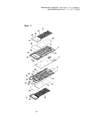
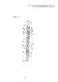
Фиг. 1 представляет собой покомпонентный вид в аксонометрии нагревательного устройства в соответствии с вариантом выполнения изобретения и схематический вид верхней пластины кассеты в направлении, в котором видна внутренняя часть верхней пластины.FIG. 1 is an exploded perspective view of a heating device according to an embodiment of the invention and a schematic view of a cartridge upper plate in a direction in which the inside of the upper plate is visible.
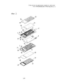
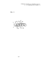
Фиг. 2 представляет собой покомпонентный вид в аксонометрии нагревательного устройства в соответствии с вариантом выполнения изобретения и схематический вид верхней пластины кассеты в направлении, в котором видна внутренняя часть нижней пластины.FIG. 2 is an exploded perspective view of a heating device according to an embodiment of the invention and a schematic view of a cartridge upper plate in a direction in which the inside of the lower plate is visible.
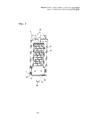
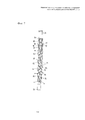
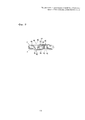
Фиг. 3 представляет собой вид в плане нагревательного устройства в соответствии с вариантом выполнения изобретения в собранном состоянии.FIG. 3 is a plan view of a heating device according to an embodiment of the invention in an assembled state.
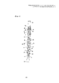
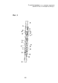
Фиг. 4 представляет собой вид в разрезе нагревательного устройства в соответствии с вариантом выполнения изобретения, взятом продольно по выходным каналам нагревательного устройства.FIG. 4 is a sectional view of a heating device in accordance with an embodiment of the invention, taken longitudinally along the output channels of the heating device.
Фиг. 5 представляет собой вид в разрезе нагревательного устройства в соответствии с вариантом выполнения изобретения, взятым продольно по выпускному каналу нагревательного устройства.FIG. 5 is a cross-sectional view of a heating device in accordance with an embodiment of the invention, taken longitudinally along the outlet of the heating device.
Фиг. 6 представляет собой вид сбоку в разрезе нагревательного устройства в соответствии с вариантом выполнения изобретения, взятым по выпускному каналу нагревательного устройства.FIG. 6 is a cross-sectional side view of a heating device according to an embodiment of the invention taken along the exhaust channel of a heating device.
Фиг. 7 представляет собой схематическую иллюстрацию состояния, при котором работает блокирующее средство, предназначенное для блокирования текучей среды в нагревательном устройстве, показанном на фиг. 4.FIG. 7 is a schematic illustration of a state in which blocking means for blocking a fluid in the heating device shown in FIG. four.
Фиг. 8 представляет собой схематическую иллюстрацию состояния, при котором работает блокирующее средство, предназначенное для блокирования текучей среды в нагревательном устройстве, показанном на фиг. 5.FIG. 8 is a schematic illustration of a state in which blocking means for blocking a fluid in the heating device shown in FIG. 5.
Фиг. 9 представляет собой схематическую иллюстрацию состояния, при котором работает блокирующее средство, предназначенное для блокирования текучей среды в нагревательном устройстве, показанном на фиг. 6.FIG. 9 is a schematic illustration of a state in which blocking means for blocking a fluid in the heating device shown in FIG. 6.
ПОДРОБНОЕ ОПИСАНИЕ ИЗОБРЕТЕНИЯDETAILED DESCRIPTION OF THE INVENTION
Ниже приведено подробное описание медицинского нагревательного устройства в соответствии с предпочтительными вариантами выполнения изобретения со ссылкой на сопроводительные чертежи.The following is a detailed description of a medical heating device in accordance with preferred embodiments of the invention with reference to the accompanying drawings.
Фиг. 1 изображает покомпонентный вид в аксонометрии нагревательного устройства в соответствии с вариантом выполнения изобретения, а фиг. 3 изображает вид в плане нагревательного устройства в соответствии с вариантом выполнения изобретения в соединенном состоянии. Номером 2 позиции обозначена верхняя пластина кассеты.FIG. 1 is an exploded perspective view of a heating device according to an embodiment of the invention, and FIG. 3 is a plan view of a heating device according to an embodiment of the invention in a connected state.
Верхняя пластина 2 кассеты выполнена независимо от нижней пластины 4 кассеты, причем верхняя и нижняя пластины образуют единую кассету посредством связующих веществ и т.д. Верхняя и нижняя пластины кассеты данного варианта выполнения названы так для удобства изложения, при этом верхняя и нижняя пластины кассеты могут быть названы с взаимозаменяемостью.The
Между верхней 2 и нижней 4 пластинами установлен нагреватель 6, обеспечивающий подогрев инфузионного раствора или крови (называемых в дальнейшем текучей средой) до постоянной температуры при прохождении текучей среды.Between the upper 2 and lower 4 plates, a
Нагреватель 6 может быть плоским нагревателем, выполненным по типу печатной платы, при этом такой нагреватель может быть таким же, как широко применяемые нагреватели, или подобным им.The
В верхней и нижней пластинах 2, 4 соответственно выполнены направляющие элементы 8, 10, предназначенные для направления потока текучей среды, так что текучая среда может проходить между верхней пластиной 2 и нагревателем 6, а также между нижней пластиной 4 и нагревателем 6.In the upper and
Направляющие элементы 8, выполненные в верхней пластине 2, и направляющие элементы 10, выполненные в нижней пластине 4, проходят с наклоном в противоположных направлениях на передней и задней поверхностях нагревателя 6, как проиллюстрировано на фиг. 1.The guiding
При такой конструкции элементы 8 и 10 выполнены с возможностью прохождения по спирали вокруг нагревателя 6. Ширина элементов 8 и 10 превышает ширину нагревателя 6. Как проиллюстрировано на фиг. 2, элементы 8 и 10 могут сообщаться друг с другом вдоль обеих сторон нагревателя 6.With this design, the
В верхней и нижней пластинах 2, 4 выполнены впускной элемент 12 и выпускной элемент 14, через которые текучая среда втекает и вытекает. На фиг. 1 показано, что оба элемента 12, 14 выполнены в верхней пластине 2, однако впускной и выпускной элементы могут быть выполнены в верхней и нижней пластинах 2 и 4 в виде отдельных конструкций.An
Текучая среда, поступающая во впускной элемент 12, нагревается при прохождении к передней и задней поверхностям нагревателя 6 через каналы, образованные элементами 8 и 10, и перемещается к выпускному элементу 14. При таком процессе нагревания могут образовываться пузырьки воздуха.The fluid entering the
В соответствии с вариантом выполнения изобретения выполнены выпускные окна 16 в качестве средств, обеспечивающих выпуск таких воздушных пузырьков благодаря открытию пространства между элементами 8.In accordance with an embodiment of the invention,
Подобным образом выпускные окна 18 выполнены благодаря открытию пространства между элементами 10.Similarly, the
Помимо этого, воздушные фильтры 20 и 22, имеющие размер, по существу перекрывающий выпускные окна, выполнены так, что текучая среда не выходит из выпускных окон 16 и 18, а выходят только газы.In addition,
Соответственно, когда в текучей среде, подогреваемой нагревателем 6, образуются воздушные пузырьки, то они выпускаются через фильтры 20 и 22, в то время как текучая среда перемещается вдоль элементов 8 и 10.Accordingly, when air bubbles form in the fluid heated by the
В качестве воздушных фильтров 20 и 22 могут использоваться широко известные фильтры, поэтому их подробное описание не приведено.As
Для закрепления фильтров 20 и 22, чтобы они не перемещались в направлении выпускных окон 16 и 18, выполнены покрышки 24 и 26, оказывающие давление на фильтры 20 и 22, направленное снаружи кассеты к ее внутренней части. В покрышках 24 и 26 проделаны отверстия 27, так что соответственно воздушные пузырьки, выпущенные через фильтры 20 и 22, могут выйти в атмосферу.To fix the
В верхней и нижней пластинах 2 и 4 выполнены соответственно установочные канавки 28 и 30, в которых могут быть размещены покрышки 24 и 26 и воздушные фильтры 20 и 22. Фильтры 20 и 22 и покрышки 24 и 26 размещены в канавках 28 и 30 и соединены вместе связующими веществами.In the upper and
Верхняя и нижняя пластины 2, 4 имеют дополнительно проходящие удлинительные части 32 и 34. Удлинительные части 32 и 34 выполнены в местах, в которых они обращены друг к другу. Каждая из удлинительных частей выполнена с блокирующим средством, предназначенным для блокирования потока текучей среды.The upper and
Если подача текучей среды прекращается или завершается и при этом внутри кассеты возникает отрицательное давление, то наружный воздух может проходить в кассету. Соответственно, блокирующее средство в варианте выполнения изобретения блокирует поступление внутрь внешнего потока.If the fluid supply is interrupted or terminated and negative pressure occurs inside the cassette, then outside air may flow into the cassette. Accordingly, the blocking means in an embodiment of the invention blocks the entry into the external flow.
Помимо этого, если кассета помещена в место, расположенное ниже места расположения человека, которому подается текучая среда, то подаваемая текучая среда может пойти в обратном направлении. Соответственно блокирующее средство препятствует прохождению обратного потока текучей среды.In addition, if the cartridge is placed in a location below the location of the person to whom the fluid is supplied, then the supplied fluid can go in the opposite direction. Accordingly, the blocking means interferes with the passage of the reverse fluid flow.
Для такого воздействия в блокирующем средстве в данном варианте выполнения в последнем направляющем элементе 9 из множества направляющих элементов 10 выполнен канал Н, так что текучая среда может проходить в участок S1 через канал Н.For such an effect, in the blocking means in this embodiment, in the
Участок S1 ограничен наружным ограждающим ребром 36, выступающим в нижней пластине 4 кассеты. В противоположность этому в верхней пластине 2 кассеты выполнена канавка 37, в которую может быть вставлено наружное ограждающее ребро 36. Соответственно, верхняя и нижняя пластины кассеты могут быть тесно связаны.The portion S1 is bounded by an
Внутреннее ограждающее ребро 38 выполнено внутри участка S1, окруженного наружным ограждающим ребром 36, так, что текучая среда внутри участка S1 не проходит во внутреннее ограждающее ребро 38.The
Участок S2, окруженный внутренним ограждающим ребром 38, выполнен с возможностью сообщения с выпускным элементом 14.Section S2, surrounded by an
Наружное ограждающее ребро 36 выполнено в удлинительной части 34 нижней пластины 4. Удлинительная часть 32 верхней пластины 2 покрывает участок S1 так, что участок S1 является закрытым и изолированным. В удлинительной части 32 выполнены выходные каналы 40, так что текучая среда, имеющаяся внутри участка S1, выходит из него.The
В удлинительной части 32, в которой выполнены выходные каналы 40, выполнен выпускной канал 42 для прохождения текучей среды в участок S2.In the
Выпускной канал 42 выполнен в месте, соответствующем участку S2, сообщающемуся с выпускным элементом 14. Соответственно, когда верхняя и нижняя пластины кассеты объединены, то они могут сообщаться друг с другом.The exhaust channel 42 is made in the place corresponding to the section S2 in communication with the
Близко снаружи выходных каналов 40 и выпускного канала 42 размещен пленочный элемент 44, который прикреплен к удлинительной части 32 крепежным элементом 46, проходящим от покрышки 24.Close to the outside of the
Если пленочный элемент 44 прикреплен, то его четыре стороны прижаты и закреплены создающим давление элементом 47, выступающим вперед по периферии крепежного элемента 46.If the
Покрышка 24 и крепежный элемент 46 могут быть выполнены по отдельности или за одно целое. В крепежном элементе 46 выполнено отверстие 48, так что наружный воздух может воздействовать на пленочный элемент 44.The
Пленочный элемент 44 по толщине выполнен тонким. В качестве материала для пленочного элемента может использоваться материал термопластичного ряда с большой эластичностью, например, поликарбонат. Пленочный элемент 44 может быть выполнен из любого материала, который расширяется под действием давления и возвращается в исходное состояние при прекращении действия давления, а также является жароустойчивым и долговечным.The
В соответствие с вариантом выполнения по данному изобретению блокирующее средство может быть установлено либо в одной из верхней и нижней пластин кассеты, либо может быть выполнено как в верхней, так и в нижней пластине.In accordance with an embodiment of the present invention, the locking means can be installed either in one of the upper and lower plates of the cartridge, or it can be made in both the upper and lower plates.
Например, как проиллюстрировано на фиг. 1, выходные каналы 41, действующие так же, как и выходные каналы 40, могут быть выполнены в участке S1 нижней пластины 4, другой пленочный элемент 45, выполненный из такого же материала, что и пленочный элемент 44, может быть размещен на другой стороне участка S1, а крепежный элемент 49 может быть выполнен в покрышке 26 и объединен с нижней пластиной кассеты.For example, as illustrated in FIG. 1, the
Если блокирующее средство установлено как в верхней пластине 2, так и в нижней пластине 4, как изложено выше, то преимущество такого решения заключается в том, что объем потока текучей среды может быть гарантирован в достаточной степени. В этом случае в крепежном элементе 49 необходимо выполнить отверстие 50 для воздействия атмосферного давления на пленочный элемент 45.If the blocking means is installed both in the
В представленном варианте выполнения блокирующее средство изображено как выполненное в удлинительных частях 32 и 34 верхней пластины 2 и нижней пластины 4, а наружное ограждающее ребро 36 показано как выполненное в удлинительной части 34 нижней пластины 4, но без ограничения этим. По высоте наружное ребро 36 может быть разделено на две половины, по одной на верхней пластине 2 и нижней пластине 4, при этом верхняя пластина 2 и нижняя пластина 4 связаны вместе так, что они обращены друг к другу.In the illustrated embodiment, the locking means is shown as being made in the
В нагревательном устройстве, выполненном, как изложено выше в соответствии с вариантом выполнения изобретения, текучая среда (инфузионный раствор или кровь) проходит через впускной элемент 12 между верхней и нижней пластинами 2 и 4 и перемещается в направлении выпускного элемента 14 через каналы, образованные направляющими элементами 8.In a heating device made as described above in accordance with an embodiment of the invention, a fluid (infusion solution or blood) passes through the
При таком способе прохождения текучая среда, подогретая нагревателем 6, достигает соответствующей температуры, необходимой для введения в тело человека.With this method of passage, the fluid heated by the
При этом способе в текучей среде образуются воздушные пузырьки. Образовавшиеся воздушные пузырьки проходят через выпускные окна 16 и 18, выполненные в пластинах 2 и 4, как проиллюстрировано на фиг. 4. Поскольку выпускные окна 16 и 18 покрыты соответственно воздушными фильтрами 20 и 22, то воздушные пузырьки, образовавшиеся в текучей среде, выходят в атмосферу через воздушные фильтры 20 и 22.With this method, air bubbles are formed in the fluid. The resulting air bubbles pass through the
Текучая среда, нагретая, как изложено выше, проходит через канал Н, когда воздух уже удален из нее, доходит до участков S1, выполненных соответственно в верхней и нижней пластинах 2 и 4, и выходит через выходные каналы 40 и 41, выполненные в этих участках.The fluid heated, as described above, passes through the channel H when the air has already been removed from it, reaches the sections S1 made respectively in the upper and
Снаружи выходные каналы 40 и 41 покрыты пленочными элементами 44 и 45. Под воздействием давления текучей среды, выходящей через выходные каналы 40 и 41, пленочные элементы расширяются, так что происходит соединение блокированных выходных каналов 40 и выпускного канала 42, как проиллюстрировано на фиг. 4.Outside, the
Таким образом, текучая среда проходит в выпускной канал 42 через выходные каналы 40 за счет расширения пленочных элементов 44 и 45. Соответственно, текучая среда может дойти до участка S2, так как выпускной канал 42 входит в контакт с участком S2 с образованием канала, посредством которого выпускной канал 42 присоединен к участку S2, как проиллюстрировано на фиг. 4, 5 и 6.Thus, the fluid enters the outlet channel 42 through the
Поскольку канал S2 присоединен к выпускному элементу 14, то может быть нормально подан инфузионный раствор или кровь (т.е. текучая среда) в подогретом состоянии, когда пузырьки воздуха уже удалены.Since the channel S2 is connected to the
Однако, если подача текучей среды завершена из такого нормального состояния подачи текучей среды, то давление внутри канала, в котором по существу расположены пластины 2 и 4, уменьшается.However, if the fluid supply is completed from such a normal fluid supply state, then the pressure inside the channel in which the
Когда давление внутри верхней и нижней пластин кассеты становится отрицательным, то предложенное медицинское нагревательное устройство блокирует проточный канал, образованный верхней и нижней пластинами, так что наружный воздух не проходит в тело человека.When the pressure inside the upper and lower plates of the cartridge becomes negative, the proposed medical heating device blocks the flow channel formed by the upper and lower plates, so that outside air does not pass into the human body.
То есть, когда внутри пластин 2 и 4 возникает отрицательное давление, то пленочные элементы 44 и 45 возвращаются в исходное состояние, так как исчезает расширяющее их усилие, вызванное давлением потока текучей среды. Соответственно, как проиллюстрировано на фиг. 7, 8 и 9, пленочные элементы 44 и 45 плотно прилегают к поверхностям выходных каналов 40 и выпускного канала 42, выполненного в удлинительной части 32.That is, when a negative pressure occurs inside the
Если выходные каналы 40 и выпускной канал 42 покрыты снаружи, как изложено выше, то происходит блокировка проточного канала для текучей среды, проходящей через каналы 40 и 42. Соответственно, текучая среда не сможет пройти.If the
Такое блокирование текучей среды аналогичным образом происходит в верхней пластине 2 и нижней пластине 4 кассеты.Such fluid blocking likewise occurs in the
Если состояние текучей среды в кассете изменяется от нормального состояния к состоянию отрицательного давления, то происходит ее незамедлительное блокирование за счет усилия расширения и восстановления пленочных элементов.If the state of the fluid in the cartridge changes from a normal state to a state of negative pressure, then it immediately blocks due to the expansion and restoration of the film elements.
Помимо этого, такое блокирующее действие может препятствовать возврату потока подаваемой текучей среды, даже если текучая среда, подаваемая в тело человека, проходит обратно вследствие возникновения отрицательного давления внутри кассеты, вызванного физическими факторами.In addition, such a blocking effect may prevent the return of the flow of the supplied fluid, even if the fluid supplied to the human body passes back due to the occurrence of negative pressure inside the cartridge caused by physical factors.
Claims (17)
Applications Claiming Priority (3)
| Application Number | Priority Date | Filing Date | Title |
|---|---|---|---|
| KR1020130050172A KR101354722B1 (en) | 2013-05-03 | 2013-05-03 | Warmer for medical device having means for blocking fluid flow |
| KR10-2013-0050172 | 2013-05-03 | ||
| PCT/KR2013/011712 WO2014178512A1 (en) | 2013-05-03 | 2013-12-17 | Medical heating device having means for blocking flow of fluid |
Publications (1)
| Publication Number | Publication Date |
|---|---|
| RU2614503C1 true RU2614503C1 (en) | 2017-03-28 |
Family
ID=50146278
Family Applications (1)
| Application Number | Title | Priority Date | Filing Date |
|---|---|---|---|
| RU2015129009A RU2614503C1 (en) | 2013-05-03 | 2013-12-17 | Heating medical device, containing the fluid flow blocking unit |
Country Status (8)
| Country | Link |
|---|---|
| US (1) | US9833580B2 (en) |
| EP (1) | EP2929899B1 (en) |
| JP (1) | JP5996128B2 (en) |
| KR (1) | KR101354722B1 (en) |
| CN (1) | CN104994895B (en) |
| CA (1) | CA2897590C (en) |
| RU (1) | RU2614503C1 (en) |
| WO (1) | WO2014178512A1 (en) |
Families Citing this family (6)
| Publication number | Priority date | Publication date | Assignee | Title |
|---|---|---|---|---|
| WO2016023034A1 (en) | 2014-08-08 | 2016-02-11 | Fremon Scientific, Inc. | Smart bag used in sensing physiological and/or physical parameters of bags containing biological substance |
| KR101920031B1 (en) | 2016-12-07 | 2018-11-19 | 김용수 | Valve assembly |
| KR101920032B1 (en) | 2016-12-07 | 2019-02-08 | 김용수 | Valve assembly |
| KR101920030B1 (en) | 2016-12-07 | 2018-11-19 | 김용수 | Valve assembly |
| CN112512603A (en) | 2018-05-07 | 2021-03-16 | 弗莱蒙科学公司 | Thawing biological material |
| CN113975549B (en) * | 2021-10-21 | 2025-07-18 | 佛山市奇汇医疗器械有限公司 | Blood transfusion and infusion exhaust box |
Citations (6)
| Publication number | Priority date | Publication date | Assignee | Title |
|---|---|---|---|---|
| US5381510A (en) * | 1991-03-15 | 1995-01-10 | In-Touch Products Co. | In-line fluid heating apparatus with gradation of heat energy from inlet to outlet |
| RU2036666C1 (en) * | 1991-11-18 | 1995-06-09 | Альберт Александрович Ефремов | Perfusion heat-treatment apparatus |
| CN101331951A (en) * | 2007-06-29 | 2008-12-31 | 丹东海沃水产有限公司 | Preparation method of DHA jellyfish egg polypeptides freeze-dry powder |
| EP2311514A2 (en) * | 2008-07-22 | 2011-04-20 | Jae Sang Park | Medical heating device |
| JP4716722B2 (en) * | 2003-12-12 | 2011-07-06 | 旭化成ケミカルズ株式会社 | Thermoplastic resin composition |
| KR20120081543A (en) * | 2011-01-11 | 2012-07-19 | 박재상 | Warmer for medical treatment |
Family Cites Families (13)
| Publication number | Priority date | Publication date | Assignee | Title |
|---|---|---|---|---|
| FR2405610A1 (en) * | 1977-10-07 | 1979-05-04 | Leboeuf Lola | ELECTRIC HEATING PLATE DEVICE FOR BLOOD TRANSFUSION DEVICE |
| EP0112510A1 (en) * | 1982-11-30 | 1984-07-04 | "Continental Belro" | Process and apparatus to control the concentration of specific substances in a liquid |
| NL1015999C2 (en) * | 2000-08-23 | 2002-02-26 | A J Van Liebergen Holding B V | Device for heating blood or other physiological fluids. |
| DE60307280T2 (en) | 2002-07-09 | 2007-10-18 | Gambro Lundia Ab | SUPPORTING ELEMENT FOR AN EXTRACORPORAL TRANSPORT HOSE |
| JP2004105599A (en) * | 2002-09-20 | 2004-04-08 | Futaba Corp | Warmer |
| JP2004215758A (en) * | 2003-01-10 | 2004-08-05 | Futaba Corp | Container for warming liquid and warmer thereof |
| JP2004337353A (en) | 2003-05-15 | 2004-12-02 | Futaba Corp | Container for heating liquid and its manufacturing method |
| KR100553129B1 (en) | 2003-09-17 | 2006-02-20 | 박재상 | Heating device with heater made by PC method |
| US8444600B2 (en) * | 2003-09-17 | 2013-05-21 | Jae Sang Park | Replaceable heating cartridge for use with a warming device for medical treatment |
| KR100577406B1 (en) * | 2003-09-17 | 2006-05-10 | 박재상 | Heater manufacturing method and heater using PCC method |
| US7563248B2 (en) | 2005-03-17 | 2009-07-21 | Smisson-Cartledge Biomedical Llc | Infusion fluid heat exchanger and cartridge |
| US20080262409A1 (en) * | 2007-04-23 | 2008-10-23 | Joel Brian Derrico | High flow rate disposable cassette heat exchanger |
| ES2396748T3 (en) | 2008-06-30 | 2013-02-25 | Animas Corporation | Volumetric Micropump |
-
2013
- 2013-05-03 KR KR1020130050172A patent/KR101354722B1/en active Active
- 2013-12-17 EP EP13883578.0A patent/EP2929899B1/en active Active
- 2013-12-17 WO PCT/KR2013/011712 patent/WO2014178512A1/en not_active Ceased
- 2013-12-17 CN CN201380072548.0A patent/CN104994895B/en active Active
- 2013-12-17 RU RU2015129009A patent/RU2614503C1/en active
- 2013-12-17 JP JP2015551595A patent/JP5996128B2/en active Active
- 2013-12-17 US US14/759,446 patent/US9833580B2/en active Active
- 2013-12-17 CA CA2897590A patent/CA2897590C/en active Active
Patent Citations (6)
| Publication number | Priority date | Publication date | Assignee | Title |
|---|---|---|---|---|
| US5381510A (en) * | 1991-03-15 | 1995-01-10 | In-Touch Products Co. | In-line fluid heating apparatus with gradation of heat energy from inlet to outlet |
| RU2036666C1 (en) * | 1991-11-18 | 1995-06-09 | Альберт Александрович Ефремов | Perfusion heat-treatment apparatus |
| JP4716722B2 (en) * | 2003-12-12 | 2011-07-06 | 旭化成ケミカルズ株式会社 | Thermoplastic resin composition |
| CN101331951A (en) * | 2007-06-29 | 2008-12-31 | 丹东海沃水产有限公司 | Preparation method of DHA jellyfish egg polypeptides freeze-dry powder |
| EP2311514A2 (en) * | 2008-07-22 | 2011-04-20 | Jae Sang Park | Medical heating device |
| KR20120081543A (en) * | 2011-01-11 | 2012-07-19 | 박재상 | Warmer for medical treatment |
Also Published As
| Publication number | Publication date |
|---|---|
| KR101354722B1 (en) | 2014-01-24 |
| EP2929899B1 (en) | 2021-11-24 |
| EP2929899A1 (en) | 2015-10-14 |
| CA2897590C (en) | 2016-02-16 |
| CN104994895A (en) | 2015-10-21 |
| CN104994895B (en) | 2017-03-08 |
| EP2929899A4 (en) | 2016-08-24 |
| JP5996128B2 (en) | 2016-09-21 |
| US20160045679A1 (en) | 2016-02-18 |
| WO2014178512A1 (en) | 2014-11-06 |
| CA2897590A1 (en) | 2014-11-06 |
| JP2016505340A (en) | 2016-02-25 |
| US9833580B2 (en) | 2017-12-05 |
Similar Documents
| Publication | Publication Date | Title |
|---|---|---|
| RU2614503C1 (en) | Heating medical device, containing the fluid flow blocking unit | |
| JP5499028B2 (en) | Medical heating device | |
| TWI453043B (en) | Intravenous filter | |
| US10791977B2 (en) | Laser lancing device | |
| KR101261748B1 (en) | Warmer for medical treatment | |
| CA2980943A1 (en) | Cold plate design in heat exchanger for intravascular temperature management catheter and/or heat exchange pad | |
| US8224166B2 (en) | Liquid warming bag and bag warmer | |
| US9834044B2 (en) | Device for fixing an electronic box in the wheel of a vehicle | |
| US20170138633A1 (en) | Electric heating device for heating fluids | |
| ITMO20090194A1 (en) | OXYGENATOR DEVICE | |
| EP3010569B1 (en) | Medical heat exchanger for heating medical liquids by means of an emitter for light and medical liquid treatment device having an emitter for light | |
| KR20170055102A (en) | Air eliminate filter installated in saline drip | |
| JP7228686B2 (en) | Air filter device and chemical injection device including the same | |
| EP1982738B1 (en) | Blood filter device | |
| US20220347435A1 (en) | Cover for drug delivery tube device and drug delivery tube device set including same | |
| KR102739307B1 (en) | Sap filter | |
| ITMO20110200A1 (en) | AN OXYGENATOR OF ORGANIC FLUIDS FOR TREATMENTS OF PATIENTS IN EXTRA-REPAIR CIRCULATION | |
| KR870001592B1 (en) | Electronicolly-controlled heating device for infusion liquid | |
| US20200046914A1 (en) | Warming device and infusion system | |
| KR20190038126A (en) | Triple-filtering syringe | |
| KR20250003057A (en) | Double filter structure for fluid line | |
| KR20170082086A (en) | Air Filter installated in saline drip | |
| ITMN960033A1 (en) | ARTERIAL FILTER IN EXTRACORPOREAL BLOOD CIRCUIT | |
| TH95599A (en) | Improved water supply emitter unit | |
| ITMO20010099A1 (en) | BIOARTIFICIAL ORGAN |
Legal Events
| Date | Code | Title | Description |
|---|---|---|---|
| PC41 | Official registration of the transfer of exclusive right |
Effective date: 20210309 |