RU2614135C2 - Lighting device and method of lighting device production - Google Patents
Lighting device and method of lighting device production Download PDFInfo
- Publication number
- RU2614135C2 RU2614135C2 RU2013133913A RU2013133913A RU2614135C2 RU 2614135 C2 RU2614135 C2 RU 2614135C2 RU 2013133913 A RU2013133913 A RU 2013133913A RU 2013133913 A RU2013133913 A RU 2013133913A RU 2614135 C2 RU2614135 C2 RU 2614135C2
- Authority
- RU
- Russia
- Prior art keywords
- emitting element
- light
- light emitting
- lighting device
- lighting
- Prior art date
Links
Images

Classifications
-
- F—MECHANICAL ENGINEERING; LIGHTING; HEATING; WEAPONS; BLASTING
- F21—LIGHTING
- F21K—NON-ELECTRIC LIGHT SOURCES USING LUMINESCENCE; LIGHT SOURCES USING ELECTROCHEMILUMINESCENCE; LIGHT SOURCES USING CHARGES OF COMBUSTIBLE MATERIAL; LIGHT SOURCES USING SEMICONDUCTOR DEVICES AS LIGHT-GENERATING ELEMENTS; LIGHT SOURCES NOT OTHERWISE PROVIDED FOR
- F21K99/00—Subject matter not provided for in other groups of this subclass
-
- F—MECHANICAL ENGINEERING; LIGHTING; HEATING; WEAPONS; BLASTING
- F21—LIGHTING
- F21V—FUNCTIONAL FEATURES OR DETAILS OF LIGHTING DEVICES OR SYSTEMS THEREOF; STRUCTURAL COMBINATIONS OF LIGHTING DEVICES WITH OTHER ARTICLES, NOT OTHERWISE PROVIDED FOR
- F21V23/00—Arrangement of electric circuit elements in or on lighting devices
- F21V23/003—Arrangement of electric circuit elements in or on lighting devices the elements being electronics drivers or controllers for operating the light source, e.g. for a LED array
-
- F—MECHANICAL ENGINEERING; LIGHTING; HEATING; WEAPONS; BLASTING
- F21—LIGHTING
- F21K—NON-ELECTRIC LIGHT SOURCES USING LUMINESCENCE; LIGHT SOURCES USING ELECTROCHEMILUMINESCENCE; LIGHT SOURCES USING CHARGES OF COMBUSTIBLE MATERIAL; LIGHT SOURCES USING SEMICONDUCTOR DEVICES AS LIGHT-GENERATING ELEMENTS; LIGHT SOURCES NOT OTHERWISE PROVIDED FOR
- F21K9/00—Light sources using semiconductor devices as light-generating elements, e.g. using light-emitting diodes [LED] or lasers
- F21K9/20—Light sources comprising attachment means
- F21K9/23—Retrofit light sources for lighting devices with a single fitting for each light source, e.g. for substitution of incandescent lamps with bayonet or threaded fittings
- F21K9/232—Retrofit light sources for lighting devices with a single fitting for each light source, e.g. for substitution of incandescent lamps with bayonet or threaded fittings specially adapted for generating an essentially omnidirectional light distribution, e.g. with a glass bulb
-
- F—MECHANICAL ENGINEERING; LIGHTING; HEATING; WEAPONS; BLASTING
- F21—LIGHTING
- F21K—NON-ELECTRIC LIGHT SOURCES USING LUMINESCENCE; LIGHT SOURCES USING ELECTROCHEMILUMINESCENCE; LIGHT SOURCES USING CHARGES OF COMBUSTIBLE MATERIAL; LIGHT SOURCES USING SEMICONDUCTOR DEVICES AS LIGHT-GENERATING ELEMENTS; LIGHT SOURCES NOT OTHERWISE PROVIDED FOR
- F21K9/00—Light sources using semiconductor devices as light-generating elements, e.g. using light-emitting diodes [LED] or lasers
- F21K9/20—Light sources comprising attachment means
- F21K9/23—Retrofit light sources for lighting devices with a single fitting for each light source, e.g. for substitution of incandescent lamps with bayonet or threaded fittings
- F21K9/238—Arrangement or mounting of circuit elements integrated in the light source
-
- F—MECHANICAL ENGINEERING; LIGHTING; HEATING; WEAPONS; BLASTING
- F21—LIGHTING
- F21K—NON-ELECTRIC LIGHT SOURCES USING LUMINESCENCE; LIGHT SOURCES USING ELECTROCHEMILUMINESCENCE; LIGHT SOURCES USING CHARGES OF COMBUSTIBLE MATERIAL; LIGHT SOURCES USING SEMICONDUCTOR DEVICES AS LIGHT-GENERATING ELEMENTS; LIGHT SOURCES NOT OTHERWISE PROVIDED FOR
- F21K9/00—Light sources using semiconductor devices as light-generating elements, e.g. using light-emitting diodes [LED] or lasers
- F21K9/60—Optical arrangements integrated in the light source, e.g. for improving the colour rendering index or the light extraction
- F21K9/61—Optical arrangements integrated in the light source, e.g. for improving the colour rendering index or the light extraction using light guides
-
- F—MECHANICAL ENGINEERING; LIGHTING; HEATING; WEAPONS; BLASTING
- F21—LIGHTING
- F21S—NON-PORTABLE LIGHTING DEVICES; SYSTEMS THEREOF; VEHICLE LIGHTING DEVICES SPECIALLY ADAPTED FOR VEHICLE EXTERIORS
- F21S10/00—Lighting devices or systems producing a varying lighting effect
- F21S10/005—Lighting devices or systems producing a varying lighting effect using light guides
-
- G—PHYSICS
- G02—OPTICS
- G02B—OPTICAL ELEMENTS, SYSTEMS OR APPARATUS
- G02B6/00—Light guides; Structural details of arrangements comprising light guides and other optical elements, e.g. couplings
- G02B6/0001—Light guides; Structural details of arrangements comprising light guides and other optical elements, e.g. couplings specially adapted for lighting devices or systems
- G02B6/0005—Light guides; Structural details of arrangements comprising light guides and other optical elements, e.g. couplings specially adapted for lighting devices or systems the light guides being of the fibre type
- G02B6/001—Light guides; Structural details of arrangements comprising light guides and other optical elements, e.g. couplings specially adapted for lighting devices or systems the light guides being of the fibre type the light being emitted along at least a portion of the lateral surface of the fibre
-
- G—PHYSICS
- G02—OPTICS
- G02B—OPTICAL ELEMENTS, SYSTEMS OR APPARATUS
- G02B6/00—Light guides; Structural details of arrangements comprising light guides and other optical elements, e.g. couplings
- G02B6/0001—Light guides; Structural details of arrangements comprising light guides and other optical elements, e.g. couplings specially adapted for lighting devices or systems
- G02B6/0011—Light guides; Structural details of arrangements comprising light guides and other optical elements, e.g. couplings specially adapted for lighting devices or systems the light guides being planar or of plate-like form
- G02B6/0013—Means for improving the coupling-in of light from the light source into the light guide
- G02B6/0015—Means for improving the coupling-in of light from the light source into the light guide provided on the surface of the light guide or in the bulk of it
- G02B6/002—Means for improving the coupling-in of light from the light source into the light guide provided on the surface of the light guide or in the bulk of it by shaping at least a portion of the light guide, e.g. with collimating, focussing or diverging surfaces
- G02B6/0021—Means for improving the coupling-in of light from the light source into the light guide provided on the surface of the light guide or in the bulk of it by shaping at least a portion of the light guide, e.g. with collimating, focussing or diverging surfaces for housing at least a part of the light source, e.g. by forming holes or recesses
-
- H—ELECTRICITY
- H05—ELECTRIC TECHNIQUES NOT OTHERWISE PROVIDED FOR
- H05K—PRINTED CIRCUITS; CASINGS OR CONSTRUCTIONAL DETAILS OF ELECTRIC APPARATUS; MANUFACTURE OF ASSEMBLAGES OF ELECTRICAL COMPONENTS
- H05K1/00—Printed circuits
- H05K1/02—Details
- H05K1/0277—Bendability or stretchability details
- H05K1/028—Bending or folding regions of flexible printed circuits
-
- F—MECHANICAL ENGINEERING; LIGHTING; HEATING; WEAPONS; BLASTING
- F21—LIGHTING
- F21S—NON-PORTABLE LIGHTING DEVICES; SYSTEMS THEREOF; VEHICLE LIGHTING DEVICES SPECIALLY ADAPTED FOR VEHICLE EXTERIORS
- F21S4/00—Lighting devices or systems using a string or strip of light sources
- F21S4/20—Lighting devices or systems using a string or strip of light sources with light sources held by or within elongate supports
- F21S4/22—Lighting devices or systems using a string or strip of light sources with light sources held by or within elongate supports flexible or deformable, e.g. into a curved shape
- F21S4/26—Lighting devices or systems using a string or strip of light sources with light sources held by or within elongate supports flexible or deformable, e.g. into a curved shape of rope form, e.g. LED lighting ropes, or of tubular form
-
- F—MECHANICAL ENGINEERING; LIGHTING; HEATING; WEAPONS; BLASTING
- F21—LIGHTING
- F21W—INDEXING SCHEME ASSOCIATED WITH SUBCLASSES F21K, F21L, F21S and F21V, RELATING TO USES OR APPLICATIONS OF LIGHTING DEVICES OR SYSTEMS
- F21W2121/00—Use or application of lighting devices or systems for decorative purposes, not provided for in codes F21W2102/00 – F21W2107/00
-
- F—MECHANICAL ENGINEERING; LIGHTING; HEATING; WEAPONS; BLASTING
- F21—LIGHTING
- F21Y—INDEXING SCHEME ASSOCIATED WITH SUBCLASSES F21K, F21L, F21S and F21V, RELATING TO THE FORM OR THE KIND OF THE LIGHT SOURCES OR OF THE COLOUR OF THE LIGHT EMITTED
- F21Y2103/00—Elongate light sources, e.g. fluorescent tubes
- F21Y2103/10—Elongate light sources, e.g. fluorescent tubes comprising a linear array of point-like light-generating elements
-
- F—MECHANICAL ENGINEERING; LIGHTING; HEATING; WEAPONS; BLASTING
- F21—LIGHTING
- F21Y—INDEXING SCHEME ASSOCIATED WITH SUBCLASSES F21K, F21L, F21S and F21V, RELATING TO THE FORM OR THE KIND OF THE LIGHT SOURCES OR OF THE COLOUR OF THE LIGHT EMITTED
- F21Y2107/00—Light sources with three-dimensionally disposed light-generating elements
- F21Y2107/70—Light sources with three-dimensionally disposed light-generating elements on flexible or deformable supports or substrates, e.g. for changing the light source into a desired form
-
- F—MECHANICAL ENGINEERING; LIGHTING; HEATING; WEAPONS; BLASTING
- F21—LIGHTING
- F21Y—INDEXING SCHEME ASSOCIATED WITH SUBCLASSES F21K, F21L, F21S and F21V, RELATING TO THE FORM OR THE KIND OF THE LIGHT SOURCES OR OF THE COLOUR OF THE LIGHT EMITTED
- F21Y2113/00—Combination of light sources
- F21Y2113/10—Combination of light sources of different colours
- F21Y2113/13—Combination of light sources of different colours comprising an assembly of point-like light sources
-
- F—MECHANICAL ENGINEERING; LIGHTING; HEATING; WEAPONS; BLASTING
- F21—LIGHTING
- F21Y—INDEXING SCHEME ASSOCIATED WITH SUBCLASSES F21K, F21L, F21S and F21V, RELATING TO THE FORM OR THE KIND OF THE LIGHT SOURCES OR OF THE COLOUR OF THE LIGHT EMITTED
- F21Y2113/00—Combination of light sources
- F21Y2113/20—Combination of light sources of different form
-
- F—MECHANICAL ENGINEERING; LIGHTING; HEATING; WEAPONS; BLASTING
- F21—LIGHTING
- F21Y—INDEXING SCHEME ASSOCIATED WITH SUBCLASSES F21K, F21L, F21S and F21V, RELATING TO THE FORM OR THE KIND OF THE LIGHT SOURCES OR OF THE COLOUR OF THE LIGHT EMITTED
- F21Y2115/00—Light-generating elements of semiconductor light sources
- F21Y2115/10—Light-emitting diodes [LED]
-
- H—ELECTRICITY
- H05—ELECTRIC TECHNIQUES NOT OTHERWISE PROVIDED FOR
- H05K—PRINTED CIRCUITS; CASINGS OR CONSTRUCTIONAL DETAILS OF ELECTRIC APPARATUS; MANUFACTURE OF ASSEMBLAGES OF ELECTRICAL COMPONENTS
- H05K1/00—Printed circuits
- H05K1/18—Printed circuits structurally associated with non-printed electric components
- H05K1/189—Printed circuits structurally associated with non-printed electric components characterised by the use of a flexible or folded printed circuit
-
- H—ELECTRICITY
- H05—ELECTRIC TECHNIQUES NOT OTHERWISE PROVIDED FOR
- H05K—PRINTED CIRCUITS; CASINGS OR CONSTRUCTIONAL DETAILS OF ELECTRIC APPARATUS; MANUFACTURE OF ASSEMBLAGES OF ELECTRICAL COMPONENTS
- H05K2201/00—Indexing scheme relating to printed circuits covered by H05K1/00
- H05K2201/05—Flexible printed circuits [FPCs]
- H05K2201/051—Rolled
-
- H—ELECTRICITY
- H05—ELECTRIC TECHNIQUES NOT OTHERWISE PROVIDED FOR
- H05K—PRINTED CIRCUITS; CASINGS OR CONSTRUCTIONAL DETAILS OF ELECTRIC APPARATUS; MANUFACTURE OF ASSEMBLAGES OF ELECTRICAL COMPONENTS
- H05K2201/00—Indexing scheme relating to printed circuits covered by H05K1/00
- H05K2201/10—Details of components or other objects attached to or integrated in a printed circuit board
- H05K2201/10007—Types of components
- H05K2201/10106—Light emitting diode [LED]
-
- H—ELECTRICITY
- H05—ELECTRIC TECHNIQUES NOT OTHERWISE PROVIDED FOR
- H05K—PRINTED CIRCUITS; CASINGS OR CONSTRUCTIONAL DETAILS OF ELECTRIC APPARATUS; MANUFACTURE OF ASSEMBLAGES OF ELECTRICAL COMPONENTS
- H05K2201/00—Indexing scheme relating to printed circuits covered by H05K1/00
- H05K2201/10—Details of components or other objects attached to or integrated in a printed circuit board
- H05K2201/10007—Types of components
- H05K2201/10113—Lamp
Landscapes
- Engineering & Computer Science (AREA)
- Physics & Mathematics (AREA)
- General Engineering & Computer Science (AREA)
- Microelectronics & Electronic Packaging (AREA)
- Optics & Photonics (AREA)
- General Physics & Mathematics (AREA)
- Non-Portable Lighting Devices Or Systems Thereof (AREA)
- Planar Illumination Modules (AREA)
- Light Guides In General And Applications Therefor (AREA)
- Illuminated Signs And Luminous Advertising (AREA)
Abstract
Description
Область техникиTechnical field
Настоящее изобретение в целом относится к области осветительных устройств.The present invention generally relates to the field of lighting devices.
Уровень техникиState of the art
Традиционные лампы накаливания могут иметь различные конструкции, такие как обычные функциональные лампочки с разными стеклами (например, с прозрачными, матовыми или цветными) и декоративные лампочки со сложными (комплексными) нитями накаливания, в которых сама нить служит для декоративных целей. Однако из-за требований к экономии энергии в осветительных устройствах, обусловленных экологической компетентностью, а также законодательством, традиционные лампы накаливания заменяют более экономичными источниками света, такими как лампы дневного света и светодиодные (LED) лампы. Такие обычные экологичные лампы не обеспечивают такое же разнообразие дизайнов, как обычные лампы накаливания.Traditional incandescent lamps can have various designs, such as ordinary functional bulbs with different glasses (for example, with transparent, matte or color) and decorative bulbs with complex (complex) filaments, in which the filament itself serves for decorative purposes. However, due to the requirements for energy savings in lighting devices due to environmental competence, as well as legislation, traditional incandescent lamps are replaced by more economical light sources such as fluorescent lamps and LED lamps. Such conventional eco-friendly lamps do not provide the same variety of designs as conventional incandescent lamps.
Решение задачи создания осветительного устройства, похожего на лампу накаливания с угольной нитью, представлено в WO2006/035349. В данном документе показано осветительное устройство, содержащее твердотельный светодиодный источник света, соединенный оптической связью с оптическим волокном, имеющим поверхность вывода. Недостаток такого осветительного устройства состоит в том, что оно не обеспечивает достаточно экономичное функциональное освещение (например, общее или рабочее освещение).The solution to the problem of creating a lighting device similar to an incandescent lamp with carbon filament is presented in WO2006 / 035349. This document shows a lighting device comprising a solid state LED light source coupled optically to an optical fiber having an output surface. The disadvantage of such a lighting device is that it does not provide sufficiently economical functional lighting (for example, general or working lighting).
Сущность изобретенияSUMMARY OF THE INVENTION
Таким образом, существует необходимость в создании альтернативных и/или новых устройств, которые позволят устранить или, по меньшей мере, уменьшить некоторые из вышеупомянутых недостатков. Настоящее изобретение было разработано с учетом вышеупомянутых соображений. Задача настоящего изобретения состоит в обеспечении лучшей альтернативы для вышеупомянутой технологии и известного уровня техники.Thus, there is a need to create alternative and / or new devices that will eliminate or at least reduce some of the aforementioned disadvantages. The present invention has been developed in view of the above considerations. An object of the present invention is to provide a better alternative for the aforementioned technology and prior art.
Говоря конкретнее, задачей настоящего изобретения является создание осветительного устройства, позволяющего обеспечивать как декоративное, так и функциональное освещение с улучшенной эффективностью. Также задачей настоящего изобретения является разработка способа изготовления такого осветительного устройства.More specifically, an object of the present invention is to provide a lighting device capable of providing both decorative and functional lighting with improved efficiency. It is also an object of the present invention to provide a method for manufacturing such a lighting device.
Эта и другая задачи настоящего изобретения решаются с помощью осветительного устройства и способа изготовления осветительного устройства, которые имеют признаки, определенные в независимых пунктах формулы изобретения. Предпочтительные варианты осуществления изобретения определены зависимыми пунктами формулы изобретения.This and other objectives of the present invention are solved using a lighting device and a method of manufacturing a lighting device that have the characteristics defined in the independent claims. Preferred embodiments of the invention are defined by the dependent claims.
Отсюда, согласно первому аспекту настоящего изобретения, обеспечено осветительное устройство. Осветительное устройство содержит первый светоизлучающий элемент, который соединен оптической связью со светопроводом, имеющим поверхность вывода света для освещения посредством светопровода. Кроме того, осветительное устройство содержит второй светоизлучающий элемент, предназначенный для непосредственного освещения из осветительного устройства.Hence, according to a first aspect of the present invention, a lighting device is provided. The lighting device comprises a first light emitting element that is optically coupled to a light guide having a light output surface for illumination by means of the light guide. In addition, the lighting device comprises a second light emitting element for direct lighting from the lighting device.
Кроме того, согласно второму аспекту изобретения, обеспечен способ изготовления осветительного устройства. Способ содержит следующие этапы, на которых: обеспечивают первый осветительный элемент; обеспечивают светопровод, имеющий поверхность вывода света; и соединяют оптической связью первый светоизлучающий элемент с упомянутым светопроводом. Кроме того, способ содержит этап, на котором обеспечивают второй светоизлучающий элемент, предназначенный для непосредственного освещения из упомянутого осветительного устройства.Furthermore, according to a second aspect of the invention, there is provided a method of manufacturing a lighting device. The method comprises the following steps, in which: provide a first lighting element; provide a light guide having a light output surface; and optically coupled the first light emitting element to said light guide. In addition, the method comprises the step of providing a second light emitting element for direct lighting from said lighting device.
Основная идея изобретения состоит в том, что свет, излучаемый первым светоизлучающим элементом, излучается из осветительного устройства посредством светопровода, а свет, излучаемый вторым светоизлучающим элементом, излучается из осветительного устройства непосредственно вторым светоизлучающим элементом. В результате светопровод и первый светоизлучающий элемент обеспечивают декоративное освещение, а второй светоизлучающий элемент обеспечивает прямое освещение (подходящее для функционального освещения).The main idea of the invention is that the light emitted from the first light emitting element is emitted from the lighting device by means of a light guide, and the light emitted from the second light emitting element is emitted from the lighting device directly by the second light emitting element. As a result, the light guide and the first light emitting element provide decorative lighting, and the second light emitting element provides direct lighting (suitable for functional lighting).
В этой связи под термином "прямое освещение" подразумевается, что большая или, по меньшей мере, значительная часть света, излучаемого вторым светоизлучающим элементом, исходит от осветительного устройства без прохождения через светопровод. Автор изобретения решил, что недостаток осветительного устройства согласно известному уровню техники состоит в потерях энергии, когда свет, излучаемый твердотельным источником света, попадает в оптическое волокно, а затем выводится из него. Отсюда, осветительное устройство известного уровня техники может быть усовершенствовано в отношении функционального освещения (такого как, например, общее освещение или рабочее освещение). Функциональное освещение может быть определено как тип освещения, при котором желательно получить от осветительного устройства как можно больше света, излучаемого твердотельным источником света.In this regard, the term "direct illumination" means that a large or at least a significant part of the light emitted by the second light emitting element comes from the lighting device without passing through the light guide. The inventor decided that the disadvantage of a lighting device according to the prior art is the loss of energy when the light emitted by a solid-state light source enters the optical fiber and then is removed from it. Hence, a prior art lighting device can be improved with respect to functional lighting (such as, for example, general lighting or work lighting). Functional lighting can be defined as the type of lighting in which it is desirable to receive as much light from a lighting device as possible from a solid state light source.
Преимущество настоящего изобретения состоит в том, что обеспеченное осветительное устройство обеспечивает как декоративный внешний вид (облик), так и функциональное освещение, при этом являясь эффективным с точки зрения энергии, так как свет, излучаемый вторым светоизлучающим элементом, исходит непосредственно от второго светоизлучающего элемента, без излишних потерь энергии.An advantage of the present invention is that the provided lighting device provides both a decorative appearance (appearance) and functional lighting, while being energy efficient, since the light emitted from the second light emitting element comes directly from the second light emitting element, without excessive energy loss.
Кроме того, преимущество настоящего изобретения состоит в том, что одно и то же осветительное устройство обеспечивает двойную функциональность (декоративное освещение и функциональное освещение), что увеличивает область применения данного осветительного устройства, так как оно может быть использовано как для декоративных целей, так и, например, для общего освещения или рабочего освещения.In addition, the advantage of the present invention is that the same lighting device provides dual functionality (decorative lighting and functional lighting), which increases the scope of this lighting device, as it can be used for decorative purposes, and for example for general lighting or work lighting.
Согласно варианту осуществления настоящего изобретения, освещение от осветительного устройства посредством светопровода и первого светоизлучающего элемента может быть предназначено для первого типа освещения. Кроме того, освещение от осветительного устройства от второго светоизлучающего элемента без светопровода может быть предназначено для второго типа освещения. Соответственно, первый тип освещения и второй тип освещения функционально и конструктивно отделены друг от друга, таким образом, чтобы каждый тип освещения можно было оптимизировать по энергоэффективности.According to an embodiment of the present invention, illumination from a lighting device by means of a light guide and a first light emitting element may be for a first type of lighting. In addition, illumination from a lighting device from a second light-emitting element without a light guide may be intended for a second type of lighting. Accordingly, the first type of lighting and the second type of lighting are functionally and structurally separated from each other, so that each type of lighting can be optimized for energy efficiency.
Согласно варианту осуществления настоящего изобретения, первый светоизлучающий элемент может быть предназначен для декоративного освещения (посредством светопровода, т.е. для первого типа освещения, как определено в предыдущем варианте осуществления), а второй светоизлучающий элемент может быть предназначен для функционального освещения (без светопровода, т.е. для второго типа освещения, как определено в предыдущем варианте осуществления).According to an embodiment of the present invention, the first light emitting element may be intended for decorative lighting (by means of a light guide, i.e., for the first type of lighting, as defined in the previous embodiment), and the second light emitting element may be intended for functional lighting (without light guide, i.e., for the second type of lighting, as defined in the previous embodiment).
Согласно варианту осуществления настоящего изобретения, сила света второго светоизлучающего элемента может быть регулируемой по отношению к силе света первого светоизлучающего элемента. Предпочтительно, сила света второго светоизлучающего элемента может быть регулируемой по отношению к силе света первого светоизлучающего элемента, при этом регулирование осуществляется в зависимости от входного сигнала на осветительном устройстве. Входной сигнал может приниматься на осветительном устройстве от регулятора силы света, присоединенного к осветительному устройству (при этом фактический приемник сигнала изменения силы света подключен к сетевому напряжению). В качестве альтернативы можно принимать входной сигнал, например, на низковольтную схему осветительного устройства (дополнительно описанную далее) посредством удаленного управления (которое приводится в действие пользователем, использующим осветительное устройство). Предпочтительно, передающая функция может быть использована таким образом, чтобы входное напряжение соответствовало особой взаимосвязи или соотношению между яркостью первого светоизлучающего элемента и яркостью второго светоизлучающего элемента. Преимущество настоящего изобретения состоит в том, что оно обеспечивает по меньшей мере два разных режима работы осветительного устройства: декоративный режим, при котором сила света второго светоизлучающего элемента меньше, чем сила света первого светоизлучающего элемента, и функциональный режим, при котором сила света второго светоизлучающего элемента больше, чем сила света первого светоизлучающего элемента. Другими словами, светопровод станет более ярким и будет давать большую часть общей светоотдачи от осветительного устройства, если сила света второго светоизлучающего элемента уменьшится в декоративном режиме, по сравнению с тем, когда осветительное устройство в функциональном режиме. В функциональном режиме сила света второго светоизлучающего элемента преобладает в общей светоотдаче от осветительного устройства.According to an embodiment of the present invention, the luminous intensity of the second light emitting element may be adjustable with respect to the luminous intensity of the first light emitting element. Preferably, the luminous intensity of the second light emitting element may be adjustable with respect to the luminous intensity of the first light emitting element, the adjustment being made depending on the input signal on the lighting device. An input signal may be received at the lighting device from a light control device connected to the lighting device (in this case, the actual light intensity change signal receiver is connected to the mains voltage). Alternatively, an input signal may be received, for example, to a low-voltage circuit of a lighting device (further described below) by remote control (which is driven by a user using a lighting device). Preferably, the transmitting function can be used so that the input voltage corresponds to a particular relationship or relationship between the brightness of the first light-emitting element and the brightness of the second light-emitting element. An advantage of the present invention is that it provides at least two different modes of operation of the lighting device: a decorative mode in which the light intensity of the second light-emitting element is less than the light intensity of the first light-emitting element, and a functional mode in which the light intensity of the second light-emitting element greater than the luminous intensity of the first light emitting element. In other words, the light guide will become brighter and will give most of the total light output from the lighting device if the light intensity of the second light-emitting element decreases in the decorative mode, compared to when the lighting device is in the functional mode. In functional mode, the light intensity of the second light-emitting element prevails in the total light output from the lighting device.
Согласно варианту осуществления настоящего изобретения по меньшей мере один из второго светоизлучающего элемента и первого светоизлучающего элемента может быть регулируемым, что является предпочтительным в случае, если при этом обеспечивается плавный переход между двумя ранее упомянутыми режимами работы осветительного устройства. Кроме того, первый светоизлучающий элемент и второй светоизлучающий элемент можно регулировать одновременно и/или по отдельности (индивидуально) друг от друга. Например, когда силу света первого светоизлучающего элемента повышают, одновременно с этим можно повысить силу света второго светоизлучающего элемента. Такой способ регулирования можно осуществлять с использованием одного устройства регулирования силы света, общего для всех светоизлучающих элементов (что делает техническое устройство осветительного устройства достаточно простым). Отсюда, когда и первый светоизлучающий элемент, и второй светоизлучающий элемент приводят в действие при низком уровне регулирования (т.е. с небольшой силой света), общая светоотдача от осветительного устройства невелика, в результате чего светопровод становится видимым, что позволяет обеспечить декоративный эффект. В противоположность этому, когда светоизлучающие элементы приводят в действие с высоким уровнем мощности (т.е. с большой силой света), общая светоотдача от осветительного устройства является высокой, тем самым, обеспечивая функциональное освещение. Следует заметить, что способ регулирования с помощью общего регулятора напоминает функционирование традиционного осветительного устройства типа лампы накаливания.According to an embodiment of the present invention, at least one of the second light emitting element and the first light emitting element may be adjustable, which is preferable if this ensures a smooth transition between the two previously mentioned operating modes of the lighting device. In addition, the first light emitting element and the second light emitting element can be adjusted simultaneously and / or separately (individually) from each other. For example, when the luminous intensity of the first light-emitting element is increased, at the same time, the luminous intensity of the second light-emitting element can be increased. Such a regulation method can be carried out using a single light intensity control device common to all light emitting elements (which makes the technical device of the lighting device quite simple). Hence, when both the first light-emitting element and the second light-emitting element are driven at a low level of regulation (i.e., with a small light intensity), the total light output from the lighting device is small, as a result of which the light guide becomes visible, which allows for a decorative effect. In contrast, when the light emitting elements are driven with a high power level (i.e., with a high light intensity), the overall light output from the lighting device is high, thereby providing functional lighting. It should be noted that the control method using a common controller resembles the operation of a traditional lighting device such as an incandescent lamp.
Согласно другому примеру, когда светоизлучающие элементы регулируют по отдельности, сила света первого светоизлучающего элемента увеличивается, в то время как сила света второго светоизлучающего элемента немного уменьшается. Вышеупомянутые эффекты (например, тот факт, что функционирование данного устройства подобно функционированию традиционного осветительного устройства типа лампы накаливания), могут быть достигнуты и даже усилены, если первый светоизлучающий элемент и второй светоизлучающий элемент имеют разную силу света.According to another example, when the light emitting elements are individually controlled, the luminous intensity of the first light emitting element increases, while the luminous intensity of the second light emitting element decreases slightly. The aforementioned effects (for example, the fact that the operation of this device is similar to the operation of a traditional lighting device such as an incandescent lamp) can be achieved and even enhanced if the first light emitting element and the second light emitting element have different luminous intensities.
Согласно варианту осуществления настоящего изобретения, длина волны (цвет) света, излучаемого первым светоизлучающим элементом, регулируется, предпочтительно в ответ на входной сигнал в осветительное устройство. Например, цвет первого светоизлучающего элемента может регулироваться так, чтобы быть красным/янтарным в декоративном режиме и желтым/белым в функциональном режиме. Согласно одному из вариантов осуществления, входной сигнал, поступающий к осветительному устройству, может представлять собой электрический ток или напряжение, подаваемые на осветительное устройство. Кроме того, осветительное устройство может содержать схему с передаточной функцией, коррелирующей входной сигнал со светоотдачей и/или цветом света первого и второго светоизлучающих элементов. В качестве иллюстрирующего примера, для входного сигнала низкого уровня (такого как приглушенный свет традиционной лампы накаливания), первый светоизлучающий элемент может обеспечить красный/янтарный цвет и относительно небольшую силу света, причем второй светоизлучающий элемент предпочтительно можно отключить. Чем сильнее входной сигнал, тем более желтым/белым может становиться первый светоизлучающий элемент (и тем сильнее повышается светоотдача от первого светоизлучающего элемента), и при определенном пороговом значении входного сигнала второй светоизлучающий элемент включается, и светоотдача медленно увеличивается.According to an embodiment of the present invention, the wavelength (color) of the light emitted by the first light emitting element is adjusted, preferably in response to an input signal to the lighting device. For example, the color of the first light emitting element may be adjusted to be red / amber in decorative mode and yellow / white in functional mode. According to one embodiment, the input to the lighting device may be electric current or voltage supplied to the lighting device. In addition, the lighting device may include a circuit with a transfer function that correlates the input signal with the light output and / or light color of the first and second light-emitting elements. As an illustrative example, for a low level input signal (such as the dimmed light of a conventional incandescent lamp), the first light emitting element can provide a red / amber color and relatively low light intensity, the second light emitting element being preferably turned off. The stronger the input signal, the more yellow / white the first light emitting element can become (and the stronger the light output from the first light emitting element increases), and at a certain threshold value of the input signal, the second light emitting element turns on, and light output increases slowly.
Согласно другим вариантам осуществления настоящего изобретения, светопровод может содержать оптическое волокно, при этом предпочтительно, чтобы оптическое волокно напоминало угольную нить. В качестве альтернативы светопровод может содержать светопроводящую пластину, которая может иметь любой дизайн. Например, светопровод может принимать любую объемную форму.According to other embodiments of the present invention, the light guide may comprise an optical fiber, while it is preferred that the optical fiber resembles a carbon fiber. Alternatively, the light guide may comprise a light guide plate, which may be of any design. For example, a light guide can take any three-dimensional shape.
Согласно варианту осуществления настоящего изобретения, светопровод может быть снабжен средством рассеивания для вывода света. Средство рассеивания усиливает вывод света, направляемого в светопровод, и, таким образом, делает светопровод более четко видимым.According to an embodiment of the present invention, the light guide may be provided with diffusion means for outputting light. The scattering means enhances the output of the light directed into the light guide, and thus makes the light guide more clearly visible.
Согласно варианту осуществления изобретения, структура поверхности вывода света (например, шероховатость поверхности) может быть выбрана таким образом, чтобы регулировать рассеивание света. Кроме того, светопровод может содержать (рассеивающие) частицы и/или пузырьки газа/вакуума, для вывода света. Другими словами, искажения оптических характеристик светопровода предусмотрены для рассеивания определенной части света. Данные искажения могут быть на поверхности/на краю светопровода и/или внутри светопровода. В общем, любое оптическое искажение, приводящее к изменению угла падения света, может привести к тому, что свет будет выводиться из светопровода. Искажения в объемном светопроводе могут быть получены, например, местным нагревом с помощью лазера.According to an embodiment of the invention, the structure of the light output surface (for example, the surface roughness) can be selected so as to control light scattering. In addition, the light guide may contain (scattering) particles and / or gas / vacuum bubbles to output light. In other words, distortion of the optical characteristics of the light guide is provided for scattering a certain part of the light. These distortions may be on the surface / on the edge of the light guide and / or inside the light guide. In general, any optical distortion resulting in a change in the angle of incidence of light can cause light to be emitted from the light guide. Distortions in the bulk light guide can be obtained, for example, by local heating with a laser.
Согласно варианту осуществления настоящего изобретения по меньшей мере один из первого светоизлучающего элемента и второго светоизлучающего элемента может содержать, по меньшей мере, один светодиод (LED), и преимущество изобретения в данном случае состоит в том, что светодиоды представляют собой высокоэффективные точечные источники света, доступные в нескольких разных цветовых вариантах, что позволяет создавать различные дизайны осветительного устройства. Кроме того, светодиод может быть лазерным светодиодом, который предпочтителен с той точки зрения, что он улучшает вывод света в светопровод.According to an embodiment of the present invention, at least one of the first light emitting element and the second light emitting element may comprise at least one light emitting diode (LED), and an advantage of the invention in this case is that the light emitting diodes are highly efficient point light sources available in several different color options, which allows you to create different designs of the lighting device. In addition, the LED may be a laser LED, which is preferred in that it improves the light output to the light guide.
Согласно варианту осуществления изобретения, в светопроводе может быть обеспечена цепочка из множества светодиодов.According to an embodiment of the invention, a string of multiple LEDs can be provided in the light guide.
Согласно варианту осуществления настоящего изобретения, осветительное устройство может дополнительно содержать оболочку, закрывающую первый светоизлучающий элемент, второй светоизлучающий элемент и светопровод, что является предпочтительным, чтобы светоизлучающие элементы и светопровод были защищены от повреждений и пыли. Кроме того, осветительное устройство будет напоминать традиционную лампу накаливания.According to an embodiment of the present invention, the lighting device may further comprise a sheath covering the first light emitting element, the second light emitting element and the light guide, which is preferable that the light emitting elements and the light guide are protected from damage and dust. In addition, the lighting device will resemble a traditional incandescent lamp.
Согласно варианту осуществления настоящего изобретения, осветительное устройство может дополнительно содержать основание, на котором расположены первый светоизлучающий элемент и второй светоизлучающий элемент.According to an embodiment of the present invention, the lighting device may further comprise a base on which the first light emitting element and the second light emitting element are located.
Если потребуется, осветительное устройство может дополнительно содержать рассеивающий элемент, расположенный поверх второго светоизлучающего элемента, например, в виде пластины, закрывающей второй светоизлучающий элемент(ы). Такой рассеивающий элемент предпочтителен, так как при его наличии отдельный светоизлучающий элемент менее заметен и обеспечивает более равномерное распределение света, чем без рассеивающего элемента.If required, the lighting device may further comprise a diffusing element located on top of the second light emitting element, for example, in the form of a plate covering the second light emitting element (s). Such a scattering element is preferable since, if present, a separate light emitting element is less visible and provides a more even distribution of light than without a scattering element.
Дополнительные задачи, признаки и преимущества данного изобретения станут более очевидными при изучении подробного описания, чертежей и прилагаемой формулы изобретения. Специалисты в данной области техники поймут, что различные признаки настоящего изобретения могут сочетаться для создания различных вариантов осуществления, которые отличаются от описанных ранее. В частности, следует понимать, что различные варианты осуществления осветительного устройства сочетаются со способом, определенным в соответствии со вторым аспектом изобретения.Additional objectives, features and advantages of the present invention will become more apparent when studying the detailed description, drawings and the attached claims. Specialists in the art will understand that various features of the present invention can be combined to create various embodiments that differ from those described previously. In particular, it should be understood that various embodiments of the lighting device are combined with the method defined in accordance with the second aspect of the invention.
Краткое описание чертежейBrief Description of the Drawings
Все ранее перечисленное, равно как и дополнительные задачи, признаки и преимущества данного изобретения, будет легче понять при прочтении последующего иллюстративного и неограничивающего подробного описания предпочтительных вариантов осуществления настоящего изобретения, со ссылками на прилагаемые чертежи, на которых:All of the above, as well as additional objectives, features and advantages of the present invention, will be easier to understand when reading the following illustrative and non-limiting detailed description of preferred embodiments of the present invention, with reference to the accompanying drawings, in which:
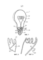
на Фиг. 1 показано осветительное устройство согласно варианту осуществления настоящего изобретения;in FIG. 1 shows a lighting device according to an embodiment of the present invention;
на Фиг. 2 показан светопровод согласно варианту осуществления настоящего изобретения;in FIG. 2 shows a light guide according to an embodiment of the present invention;
на Фиг. 3 показан светопровод согласно другому варианту осуществления настоящего изобретения; иin FIG. 3 shows a light guide according to another embodiment of the present invention; and
Фиг. 4 представляет собой общую схему способа изготовления осветительного устройства согласно варианту осуществления настоящего изобретения.FIG. 4 is a general diagram of a method for manufacturing a lighting device according to an embodiment of the present invention.
Подробное описание вариантов осуществленияDetailed Description of Embodiments
На Фиг. 1 представлено осветительное устройство согласно варианту осуществления настоящего изобретения.In FIG. 1 shows a lighting device according to an embodiment of the present invention.
На Фиг. 1 показано осветительное устройство 1, содержащее первый светоизлучающий элемент 101 и второй светоизлучающий элемент 102. Первый светоизлучающий элемент 101 соединен оптической связью со светопроводом 110, имеющим поверхность 111 вывода. Оптическую связь можно обеспечить, например, посредством оптического элемента (не показанного на чертеже), между первым светоизлучающим элементом 101 и светопроводом 110, или посредством связи первого светоизлучающего элемента 101 непосредственно со светопроводом 110, как показано на Фиг. 1.In FIG. 1 shows a lighting device 1 comprising a first
Если потребуется осветительное устройство может быть снабжено дополнительными первыми светоизлучающими элементами, связанными оптической связью со светопроводом 110. Например, первый светоизлучающий элемент может быть связан с одним концом светопровода 110, а другой первый светоизлучающий элемент может быть связан с другим концом светопровода 110 (расположенного напротив первого конца).If required, the lighting device may be provided with additional first light emitting elements coupled optically to the
Кроме того, осветительное устройство может быть снабжено дополнительными вторыми светоизлучающими элементами 102 для обеспечения функционального освещения.In addition, the lighting device may be provided with additional second
Первый светоизлучающий элемент 101 и/или второй светоизлучающий элемент 102 могут, например, представлять собой светодиоды, такие как, например, лазерные светодиоды. Например, в качестве первого светоизлучающего элемента 101 может быть использован светодиод янтарного цвета, дающий теплый свет, в результате чего светопровод выглядит как нить накала, дающая теплый свет (когда первый осветительный элемент приводят в действие). В качестве альтернативы можно, например, покрыть фосфором (или любым другим материалом, преобразующим длину волны), верхнюю часть светопровода (т.е. место около поверхности вывода светопровода) и выбрать фосфор, обеспечивающий свет теплого цвета. Согласно другому примеру, первый светоизлучающий элемент 101 может содержать красный светодиод, зеленый светодиод и синий светодиод, тем самым обеспечивая белый свет, который может быть модулирован в различные цвета путем управления светодиодами красного, зеленого и синего цвета.The first
Кроме того, светодиод более холодного цвета (который может быть более эффективным), например белого, может быть использован в качестве второго светоизлучающего элемента 102, тем самым, обеспечивая свет, подходящий для функционального освещения. Согласно другому примеру, второй светоизлучающий элемент 102 может содержать красный светодиод, зеленый светодиод и синий светодиод, тем самым, обеспечивая белый свет, который может быть модулирован в различные цвета путем управления светодиодами красного, зеленого и синего цвета. Однако следует понимать, что изобретение не ограничивается упомянутой цветовой конфигурацией, и светоизлучающие элементы 101, 102 в осветительном устройстве могут иметь любой цвет.In addition, a colder LED (which may be more effective), such as white, can be used as the second
Светопровод 110 может содержать оптическое волокно, такое как оптический проводник, изготовленный из подходящего материала, такого как пластик или стекловолокно. Использование стекловолокна предпочтительно, из-за его оптического качества и свойств материала (например, чувствительности к нагреву). Оптическое волокно может быть более длинным или более коротким, что позволяет получить более простую или сложную конструкцию. Например, оптическое волокно может быть намотано по спирали, чтобы оно было похоже на традиционную нить накала в стиле "ретро".The
Вывод света от выводящей поверхности 111 светопровода 110 может быть достигнут (и/или усилен) различными способами. Часть света может быть выведена с помощью изгибов светопровода 110. Однако светопровод 110 может быть снабжен средством рассеивания для вывода света. В общем, любое оптическое искажение на светопроводе обеспечивает вывод света. Может быть обеспечено средство рассеивания, например, посредством шероховатой выводящей поверхности 111 (например, посредством пескоструйной обработки, нанесения царапин или формования с определенной структурой поверхности), или посредством обеспечения углублений или маленьких выступов на выводящей поверхности 111. Кроме того, частицы (например, белая краска) и пузырьки газа/вакуума (например, созданные местным нагревом с помощью лазера), могут быть обеспечены на светопроводе или внутри него, таким образом, чтобы свет рассеивался из светопровода.The light output from the
Согласно варианту осуществления настоящего изобретения, светопровод 110 может содержать по меньшей мере один соединительный канал 112, к которому может быть присоединен оптической связью первый светоизлучающий элемент 101. Преимущество настоящего изобретения состоит в том, что оно позволяет принимать и выводить большую часть света, излучаемого первым светоизлучающим элементом 101, посредством светопровода 110, и тем самым служит для декоративных целей, и при этом является значительной частью света, излучаемого вторым светоизлучающим элементом 102, который обеспечивает освещение, без значительных излишних потерь энергии при использовании светопровода любого типа.According to an embodiment of the present invention, the
Однако часть (относительно небольшая) света, излучаемого вторым светоизлучающим элементом (элементами) 102, может быть соединена со вторым светопроводом 110 посредством выводящей поверхности 111, и, таким образом, снова выводится посредством выводящей поверхности 111, тем самым способствуя свечению светопровода 110.However, a portion (relatively small) of the light emitted by the second light emitting element (s) 102 can be connected to the second
Что касается Фиг. 2, показана альтернативная конструкция светопровода согласно варианту осуществления изобретения. На Фиг. 2 показан светопровод в виде пластины 210 светопровода, связанной оптической связью с первым светоизлучающим элементом 201. Часть света, излучаемого из первого светоизлучающего элемента 201, выводится посредством кромки 211, которая может быть изогнутой (и по выбору шершавой), в результате чего нить выглядит как в обычных лампах накаливания. Кроме того, свет может выводиться посредством средства рассеивания, обеспеченного внутри пластины 210 светопровода или на поверхности пластины 210 светопровода.With reference to FIG. 2, an alternative construction of a light guide according to an embodiment of the invention is shown. In FIG. 2, a light guide is shown in the form of a
Следует понимать, что светопровод может иметь любой желаемый дизайн любой желаемой объемной формы, такой как сферическая или призматическая. Кроме того, средство рассеивания может быть обеспечено в любом желаемом месте в светопроводе или на нем. Например, средство рассеивания может образовывать рисунок (например, похожий на нить накала).It should be understood that the light guide can have any desired design of any desired three-dimensional shape, such as spherical or prismatic. In addition, dispersion means can be provided at any desired location in or on the light guide. For example, the diffuser may form a pattern (for example, similar to a filament).
На Фиг. 3 показан другой дизайн светопровода, соответствующий другому варианту осуществления изобретения. На Фиг. 3 показан светопровод 320 в виде сплошного оптического элемента 323, в котором имеется цепочка из множества светодиодов 321. Светодиод 321 может быть установлен на маленькой гибкой печатной плате 322, при этом сплошной оптический элемент 323 расположен поверх него (или образует оболочку).In FIG. 3 shows a different light guide design in accordance with another embodiment of the invention. In FIG. 3 shows a
Далее будут описаны другие варианты осуществления изобретения со ссылкой на Фиг. 1. Осветительное устройство 1 может дополнительно содержать оболочку 130, закрывающую первый светоизлучающий элемент 101, второй светоизлучающий элемент 102 и светопровод 110. Предпочтительно, чтобы оболочка 130 была прозрачной (или, по меньшей мере, полупрозрачной), таким образом, чтобы светопровод 110 был виден, чтобы обеспечивать декоративный эффект. Кроме того, оболочка 130 может быть выполнена в виде лампочки, напоминающей своим видом обычную лампу накаливания. Осветительное устройство 1 может дополнительно содержать основание 140, на котором расположен первый светоизлучающий элемент 101 и второй светоизлучающий элемент 102. Основание 140 может содержать основание байонетного типа или винтовое основание 141 (например, типа Е14, Е26 или Е27), что является предпочтительным в случаях, когда осветительное устройство может быть установлено в обычных креплениях ламп и использовано в качестве замены для традиционной лампы накаливания (в стиле ретро). Основание 140 может дополнительно содержать теплоотвод 142 для охлаждения светодиодов 101, 102. По выбору светоизлучающие элементы 101, 102 могут быть расположены таким образом, чтобы верхний участок теплоотвода 142 (или верхний участок основания 140) закрывал светоизлучающие элементы 101, 102 (как показано на Фиг. 1) для уменьшения риска прямого взгляда на них (чтобы их не было видно). Кроме того, внутренняя часть верхнего участка теплоотвода 142 может быть отражающей, таким образом, что весь свет (или, по меньшей мере, почти весь), излучаемый светоизлучающими элементами 101, 102, может выводиться из осветительного устройства.Next, other embodiments of the invention will be described with reference to FIG. 1. The lighting device 1 may further comprise a
Осветительное устройство может дополнительно содержать рассеивающий элемент (не показанный на чертеже) в виде пластины поверх вторых светоизлучающих элементов 102. Например, такая пластина может быть расположена поверх основания 140. Пластина может быть снабжена отверстием, через которое может проходить свет, испускаемый первым осветительным элементом 101, чтобы он передавался на светопровод 110.The lighting device may further comprise a diffusing element (not shown) in the form of a plate on top of the second
Осветительное устройство 1 может дополнительно содержать электронное средство 150 включения (приведения в действие) с подачей энергии для преобразования подаваемого напряжения сети в выходной сигнал, приводящий в действие светоизлучающие элементы 101, 102. Электрическое средство 150 включения может дополнительно содержать электронную схему, выполненную с возможностью управлять силой света первого светоизлучающего элемента 101 и/или второго светоизлучающего элемента 102 таким образом, чтобы сила света, излучаемого вторым светоизлучающим элементом 102, регулировалась по отношению к силе света первого светоизлучающего элемента 101. Кроме того, электронная схема может быть выполнена с возможностью незначительно модулировать яркость (или цвет) первого светоизлучающего элемента 101, или последовательно включать и выключать первый светоизлучающий элемент 101, для обеспечения эффекта пламени или мерцающего эффекта на светопроводе 110. Электронная схема может дополнительно содержать функцию преобразования для согласования входного сигнала (такого как входной ток или входное напряжение) с яркостью излучаемого света и/или с цветом свечения первого и второго светоизлучающих элементов. Электрическое средство 150 включения может управляться пультом дистанционного управления, кнопками на основании 140 или с помощью любого другого типа интерфейса пользователя.The lighting device 1 may further comprise an electronic means for switching (actuating) 150 with energy supply for converting the supplied mains voltage into an output signal driving the
Согласно варианту осуществления изобретения, первый светоизлучающий элемент 101 и/или второй светоизлучающий элемент 102 могут быть регулируемыми. Согласно варианту осуществления изобретения осветительное устройство совместимо с регуляторами для обычных ламп накаливания, таким образом, чтобы светоизлучающие элементы могли работать в приглушенном режиме.According to an embodiment of the invention, the first
Как показано на Фиг. 4, будет описан способ изготовления осветительного устройства согласно варианту осуществления настоящего изобретения. На Фиг. 4 показана общая схема способа 400 изготовления осветительного устройства. Способ содержит этап 410, на котором обеспечивают первый осветительный элемент, этап 420, на котором обеспечивают светопровод, имеющий выводящую поверхность, и этап 430, на котором связывают оптической связью первый светоизлучающий элемент со светопроводом. Кроме того, способ 400 содержит этап 440, на котором обеспечивают второй светоизлучающий элемент, предназначенный для непосредственного излучения света осветительным устройством.As shown in FIG. 4, a method for manufacturing a lighting device according to an embodiment of the present invention will be described. In FIG. 4 shows a general diagram of a
Хотя были описаны конкретные варианты осуществления, специалист в данной области техники поймет, что различные модификации и изменения возможны в рамках объема изобретения, определенного в прилагаемой формуле изобретения.Although specific embodiments have been described, one skilled in the art will understand that various modifications and changes are possible within the scope of the invention defined in the appended claims.
Например, в осветительном устройстве могут быть дополнительные светопроводы с соответствующими первыми светоизлучающими элементами. Кроме того, осветительное устройство может применяться для модернизации обычных ламп накаливания, а также в специализированных новых источниках света. Более того, данное осветительное устройство не обязательно должно выглядеть как обычная лампа накаливания. Оно также может иметь конструкцию, например, лампы трубчатой формы с соединительными элементами с обоих концов трубы.For example, in the lighting device there may be additional light guides with corresponding first light emitting elements. In addition, the lighting device can be used to upgrade conventional incandescent lamps, as well as in specialized new light sources. Moreover, this lighting device does not have to look like an ordinary incandescent lamp. It may also have a structure, for example, a tube-shaped lamp with connecting elements at both ends of the pipe.
Claims (24)
Applications Claiming Priority (3)
| Application Number | Priority Date | Filing Date | Title |
|---|---|---|---|
| EP10196396.5 | 2010-12-22 | ||
| EP10196396 | 2010-12-22 | ||
| PCT/IB2011/055565 WO2012085736A1 (en) | 2010-12-22 | 2011-12-09 | Lighting device and method for manufacturing a lighting device |
Publications (2)
| Publication Number | Publication Date |
|---|---|
| RU2013133913A RU2013133913A (en) | 2015-01-27 |
| RU2614135C2 true RU2614135C2 (en) | 2017-03-23 |
Family
ID=45444669
Family Applications (1)
| Application Number | Title | Priority Date | Filing Date |
|---|---|---|---|
| RU2013133913A RU2614135C2 (en) | 2010-12-22 | 2011-12-09 | Lighting device and method of lighting device production |
Country Status (10)
| Country | Link |
|---|---|
| US (4) | US9234635B2 (en) |
| EP (4) | EP4235016A3 (en) |
| JP (1) | JP5952828B2 (en) |
| CN (2) | CN103270363B (en) |
| BR (1) | BR112013015643A2 (en) |
| ES (1) | ES2819056T3 (en) |
| PL (2) | PL2655956T3 (en) |
| RU (1) | RU2614135C2 (en) |
| TW (1) | TWI601911B (en) |
| WO (1) | WO2012085736A1 (en) |
Families Citing this family (66)
| Publication number | Priority date | Publication date | Assignee | Title |
|---|---|---|---|---|
| US10240724B2 (en) | 2015-08-17 | 2019-03-26 | Zhejiang Super Lighting Electric Appliance Co., Ltd. | LED filament |
| US10677396B2 (en) | 2006-07-22 | 2020-06-09 | Jiaxing Super Lighting Electric Appliance Co., Ltd | LED light bulb with symmetrical filament |
| US10487987B2 (en) | 2015-08-17 | 2019-11-26 | Zhejiang Super Lighting Electric Appliance Co., Ltd. | LED filament |
| US9995474B2 (en) | 2015-06-10 | 2018-06-12 | Jiaxing Super Lighting Electric Appliance Co., Ltd. | LED filament, LED filament assembly and LED bulb |
| US10655792B2 (en) | 2014-09-28 | 2020-05-19 | Zhejiang Super Lighting Electric Appliance Co., Ltd. | LED bulb lamp |
| US10473271B2 (en) | 2015-08-17 | 2019-11-12 | Zhejiang Super Lighting Electric Appliance Co., Ltd. | LED filament module and LED light bulb |
| US10544905B2 (en) * | 2014-09-28 | 2020-01-28 | Zhejiang Super Lighting Electric Appliance Co., Ltd. | LED bulb lamp |
| US11131431B2 (en) | 2014-09-28 | 2021-09-28 | Jiaxing Super Lighting Electric Appliance Co., Ltd | LED tube lamp |
| CN103975189A (en) * | 2011-12-14 | 2014-08-06 | 通用电气照明解决方案有限责任公司 | Side-emitting guidepipe technology on led lamp to make filament effect |
| US9528689B2 (en) * | 2013-03-13 | 2016-12-27 | Palo Alto Research Center Incorporated | LED lighting device with cured structural support |
| DE102013209852A1 (en) * | 2013-05-27 | 2014-11-27 | Osram Gmbh | lamp |
| US20140355292A1 (en) * | 2013-05-30 | 2014-12-04 | Gabriel Krause | Fiber Optic Filament Lamp |
| TWI599745B (en) * | 2013-09-11 | 2017-09-21 | 晶元光電股份有限公司 | Flexible led assembly and led light bulb |
| NL2011488C2 (en) * | 2013-09-23 | 2015-03-24 | Giga Groep B V | Light bulb. |
| WO2015081804A1 (en) * | 2013-12-02 | 2015-06-11 | 张晓峰 | Spiral led filament and light bulb using spiral led filament |
| CN104747926B (en) * | 2013-12-26 | 2018-01-19 | 上海顿格电子贸易有限公司 | A kind of lumination of light emitting diode bulb and its installation method |
| WO2015124469A1 (en) * | 2014-02-24 | 2015-08-27 | Koninklijke Philips N.V. | Lamp assembly |
| RU2677687C2 (en) * | 2014-03-13 | 2019-01-21 | Филипс Лайтинг Холдинг Б.В. | Filament for lighting device |
| US9488767B2 (en) * | 2014-08-05 | 2016-11-08 | Cree, Inc. | LED based lighting system |
| EP3183490A1 (en) * | 2014-08-18 | 2017-06-28 | Philips Lighting Holding B.V. | Lighting device with remote wavelength converting element |
| USD771302S1 (en) * | 2014-09-03 | 2016-11-08 | Big Trike Inc. | Illumination diffuser |
| US11480305B2 (en) | 2014-09-25 | 2022-10-25 | Jiaxing Super Lighting Electric Appliance Co., Ltd. | LED tube lamp |
| US10845008B2 (en) | 2014-09-28 | 2020-11-24 | Zhejiang Super Lighting Electric Appliance Co., Ltd. | LED filament and LED light bulb |
| US11525547B2 (en) | 2014-09-28 | 2022-12-13 | Zhejiang Super Lighting Electric Appliance Co., Ltd | LED light bulb with curved filament |
| US11686436B2 (en) | 2014-09-28 | 2023-06-27 | Zhejiang Super Lighting Electric Appliance Co., Ltd | LED filament and light bulb using LED filament |
| US10976009B2 (en) | 2014-09-28 | 2021-04-13 | Zhejiang Super Lighting Electric Appliance Co., Ltd | LED filament light bulb |
| US11028970B2 (en) | 2014-09-28 | 2021-06-08 | Zhejiang Super Lighting Electric Appliance Co., Ltd | LED filament light bulb having organosilicon-modified polyimide resin composition filament base layer |
| US10560989B2 (en) | 2014-09-28 | 2020-02-11 | Jiaxing Super Lighting Electric Appliance Co., Ltd | LED tube lamp |
| US11073248B2 (en) | 2014-09-28 | 2021-07-27 | Zhejiang Super Lighting Electric Appliance Co., Ltd. | LED bulb lamp |
| US10784428B2 (en) | 2014-09-28 | 2020-09-22 | Zhejiang Super Lighting Electric Appliance Co., Ltd. | LED filament and LED light bulb |
| US10208898B2 (en) | 2015-04-29 | 2019-02-19 | Jiaxing Super Lighting Electric Appliance Co., Ltd. | LED tube lamp with operating modes compatible with electrical ballasts |
| US11997768B2 (en) | 2014-09-28 | 2024-05-28 | Zhejiang Super Lighting Electric Appliance Co., Ltd | LED filament and LED light bulb |
| US11085591B2 (en) | 2014-09-28 | 2021-08-10 | Zhejiang Super Lighting Electric Appliance Co., Ltd | LED light bulb with curved filament |
| US11543083B2 (en) | 2014-09-28 | 2023-01-03 | Zhejiang Super Lighting Electric Appliance Co., Ltd | LED filament and LED light bulb |
| US12007077B2 (en) | 2014-09-28 | 2024-06-11 | Zhejiang Super Lighting Electric Appliance Co., Ltd. | LED filament and LED light bulb |
| CN205213093U (en) | 2014-09-28 | 2016-05-04 | 嘉兴山蒲照明电器有限公司 | Rectification filter circuit , lamp and LED straight tube lamp |
| US11421827B2 (en) | 2015-06-19 | 2022-08-23 | Zhejiang Super Lighting Electric Appliance Co., Ltd | LED filament and LED light bulb |
| US11028973B2 (en) | 2015-03-10 | 2021-06-08 | Jiaxing Super Lighting Electric Appliance Co., Ltd. | Led tube lamp |
| US9897265B2 (en) | 2015-03-10 | 2018-02-20 | Jiaxing Super Lighting Electric Appliance Co., Ltd. | LED tube lamp having LED light strip |
| US11519565B2 (en) | 2015-03-10 | 2022-12-06 | Jiaxing Super Lighting Electric Appliance Co., Ltd | LED lamp and its power source module |
| CN106151934A (en) * | 2015-04-20 | 2016-11-23 | 葛兰菲照明有限公司 | Integrating illumination and the LED bulb of night-light function |
| CN104948956B (en) * | 2015-06-23 | 2017-03-15 | 南京邮电大学 | Conversion of white light fiber illumination device on a kind of multicomponent glass |
| US10359152B2 (en) | 2015-08-17 | 2019-07-23 | Zhejiang Super Lighting Electric Appliance Co, Ltd | LED filament and LED light bulb |
| GB2543139B (en) | 2015-08-17 | 2018-05-23 | Jiaxing Super Lighting Electric Appliance Co Ltd | LED light bulb and LED filament thereof |
| CN106555946A (en) * | 2015-09-24 | 2017-04-05 | 通用电气照明解决方案有限公司 | Illuminator |
| USD771303S1 (en) * | 2015-10-02 | 2016-11-08 | Big Trike Inc. | Illumination diffuser |
| US11035526B2 (en) | 2015-12-09 | 2021-06-15 | Jiaxing Super Lighting Electric Appliance Co., Ltd. | LED tube lamp |
| CN105508892A (en) * | 2016-01-19 | 2016-04-20 | 浙江鼎鑫工艺品有限公司 | LED simulated-filament bulb |
| CN108603637B (en) * | 2016-02-04 | 2020-07-17 | 奥斯兰姆奥普托半导体有限责任公司 | LED filament and luminous body with LED filament |
| CN109716737B (en) * | 2016-09-23 | 2022-04-26 | 昕诺飞控股有限公司 | System, method and apparatus for allocating computing resources through a network of luminaires |
| EP3619460B1 (en) * | 2017-05-02 | 2021-03-24 | Signify Holding B.V. | A lighting device and a luminaire |
| US10260683B2 (en) | 2017-05-10 | 2019-04-16 | Cree, Inc. | Solid-state lamp with LED filaments having different CCT's |
| USD843637S1 (en) * | 2017-07-17 | 2019-03-19 | Salvage Electric | Decorative lamp |
| WO2019015763A1 (en) * | 2017-07-20 | 2019-01-24 | Explorentis | Led lamp with flexible led filament, and manufacturing method |
| EP3673201B1 (en) * | 2017-08-25 | 2021-01-27 | Signify Holding B.V. | Led strip for indirect light emission |
| CN207471460U (en) * | 2017-10-27 | 2018-06-08 | 漳州立达信光电子科技有限公司 | Led lamp |
| CN109973833B (en) | 2017-12-26 | 2023-03-28 | 嘉兴山蒲照明电器有限公司 | LED filament and LED bulb |
| US10790419B2 (en) | 2017-12-26 | 2020-09-29 | Jiaxing Super Lighting Electric Appliance Co., Ltd | LED filament and LED light bulb |
| US11293597B2 (en) * | 2018-02-27 | 2022-04-05 | Signify Holding B.V. | LED filament lamp comprising a control unit |
| US10982048B2 (en) | 2018-04-17 | 2021-04-20 | Jiaxing Super Lighting Electric Appliance Co., Ltd | Organosilicon-modified polyimide resin composition and use thereof |
| JP6936418B2 (en) * | 2018-07-16 | 2021-09-15 | シグニファイ ホールディング ビー ヴィSignify Holding B.V. | LED filament lamp |
| US11454356B2 (en) | 2019-04-11 | 2022-09-27 | Signify Holding B.V. | Solid state lamp |
| WO2021094124A1 (en) | 2019-11-11 | 2021-05-20 | Signify Holding B.V. | An led filament lamp and a method of producing a spiral led filament |
| US11163100B2 (en) * | 2020-01-28 | 2021-11-02 | Lucifer Lighting Company | Light fixtures having waveguides and related methods |
| CN112097129A (en) * | 2020-08-31 | 2020-12-18 | 杭州杭科光电集团股份有限公司 | Color-controllable LED luminescent lamp |
| WO2023279559A1 (en) * | 2021-07-07 | 2023-01-12 | 杭州杭科光电集团股份有限公司 | Lamp |
Citations (6)
| Publication number | Priority date | Publication date | Assignee | Title |
|---|---|---|---|---|
| RU2178588C1 (en) * | 2000-05-03 | 2002-01-20 | Марков Валерий Николаевич | Light panel |
| RU2185567C2 (en) * | 2000-02-14 | 2002-07-20 | ООО "Научно-технический центр ОПТОНИКА" | Light-emitting tube |
| RU2265156C2 (en) * | 2001-01-31 | 2005-11-27 | Айлайт Текнолоджиз, Инк. | Lighting unit for neon light simulation |
| RU52318U1 (en) * | 2005-04-20 | 2006-03-27 | Михаил Владимирович Дубина | LIGHT SOURCE FOR SURGICAL LUMINAIRES |
| US20060152946A1 (en) * | 2004-07-06 | 2006-07-13 | Tseng-Lu Chien | Multiple light source night light |
| US20070121319A1 (en) * | 2003-07-02 | 2007-05-31 | S.C. Johnson And Son, Inc. | Color changing light devices with active ingredient and sound emission for mood enhancement |
Family Cites Families (61)
| Publication number | Priority date | Publication date | Assignee | Title |
|---|---|---|---|---|
| US5924784A (en) * | 1995-08-21 | 1999-07-20 | Chliwnyj; Alex | Microprocessor based simulated electronic flame |
| US6371637B1 (en) * | 1999-02-26 | 2002-04-16 | Radiantz, Inc. | Compact, flexible, LED array |
| TW455908B (en) * | 1999-04-20 | 2001-09-21 | Koninkl Philips Electronics Nv | Lighting system |
| JP2002057371A (en) * | 2000-08-15 | 2002-02-22 | Hukuyo Denkyu Kk | Chain led light source structure |
| US6580228B1 (en) * | 2000-08-22 | 2003-06-17 | Light Sciences Corporation | Flexible substrate mounted solid-state light sources for use in line current lamp sockets |
| US6583550B2 (en) * | 2000-10-24 | 2003-06-24 | Toyoda Gosei Co., Ltd. | Fluorescent tube with light emitting diodes |
| EP1360877A1 (en) * | 2001-02-02 | 2003-11-12 | Koninklijke Philips Electronics N.V. | Integrated light source |
| JP2002259830A (en) | 2001-02-28 | 2002-09-13 | Ricoh Co Ltd | Messaging system, method of providing message, and program |
| AU2003205508A1 (en) * | 2002-01-07 | 2003-07-24 | Patent - Treuhand - Gesellschaft Fur Elektrische Gluhlampen Mbh | Lamp |
| AU2003205509A1 (en) | 2002-01-10 | 2003-07-24 | Patent - Treuhand - Gesellschaft Fur Elektrische Gluhlampen Mbh | Lamp |
| US20030147245A1 (en) * | 2002-02-01 | 2003-08-07 | Chen Ching Shui | Structure of a mini lamp |
| TW569980U (en) | 2002-10-09 | 2004-01-01 | Shr-Ling Chen | Jacklight for vehicle |
| US6853151B2 (en) * | 2002-11-19 | 2005-02-08 | Denovo Lighting, Llc | LED retrofit lamp |
| WO2004100213A2 (en) * | 2003-05-05 | 2004-11-18 | Gelcore Llc | Led-based light bulb |
| US20080106893A1 (en) * | 2004-07-02 | 2008-05-08 | S. C. Johnson & Son, Inc. | Lamp and bulb for illumination and ambiance lighting |
| US7484860B2 (en) * | 2003-07-02 | 2009-02-03 | S.C. Johnson & Son, Inc. | Combination white light and colored LED light device with active ingredient emission |
| KR101067738B1 (en) | 2003-07-02 | 2011-09-28 | 에스.씨. 존슨 앤드 선, 인코포레이티드 | Lamp and Bulb for Illumination and Ambiance Lighting |
| US7520635B2 (en) * | 2003-07-02 | 2009-04-21 | S.C. Johnson & Son, Inc. | Structures for color changing light devices |
| US20050052885A1 (en) * | 2003-09-04 | 2005-03-10 | Amazing International Enterprise Limited | Structure of LED decoration lighting set |
| GB2408846A (en) * | 2003-12-02 | 2005-06-08 | Sung Tao Ho | LED lamp tube |
| ES2383961T3 (en) * | 2004-03-03 | 2012-06-27 | S.C. Johnson & Son, Inc. | LED light bulb with active ingredient emission |
| EP2789894B1 (en) | 2004-09-29 | 2018-12-12 | Philips Lighting Holding B.V. | Lighting device |
| WO2006081707A1 (en) * | 2005-02-06 | 2006-08-10 | He Shan Lide Electronic Enterprise Company Ltd. | A new type light hose |
| US7375476B2 (en) * | 2005-04-08 | 2008-05-20 | S.C. Johnson & Son, Inc. | Lighting device having a circuit including a plurality of light emitting diodes, and methods of controlling and calibrating lighting devices |
| US7618175B1 (en) | 2005-07-08 | 2009-11-17 | Ilight Technologies, Inc. | LED lighting system with helical fiber filament |
| JP2007165811A (en) * | 2005-12-16 | 2007-06-28 | Nichia Chem Ind Ltd | Light emitting device |
| JP2007194132A (en) * | 2006-01-20 | 2007-08-02 | Fujifilm Holdings Corp | Lighting device |
| DE102006007134A1 (en) * | 2006-02-16 | 2007-08-23 | Hella Kgaa Hueck & Co. | Lighting device for use in motor vehicles, comprises housing, housing locking, translucent cover plate, and light sources, light-guiding element is partially connected with light diffuser |
| CN201032086Y (en) * | 2006-08-07 | 2008-03-05 | 陈锦伟 | Flexible optical fiber LED lamp strip |
| US8567992B2 (en) * | 2006-09-12 | 2013-10-29 | Huizhou Light Engine Ltd. | Integrally formed light emitting diode light wire and uses thereof |
| WO2008031580A1 (en) * | 2006-09-12 | 2008-03-20 | Paul Lo | Integrally formed single piece light emitting diode light wire |
| JP4989170B2 (en) * | 2006-09-20 | 2012-08-01 | オスラム・メルコ株式会社 | Compact LED lamp |
| US20080074867A1 (en) * | 2006-09-21 | 2008-03-27 | International Development Corp. | Solar powered outdoor flicker light |
| WO2008134056A1 (en) | 2007-04-26 | 2008-11-06 | Deak-Lam Inc. | Photon energy coversion structure |
| US7600897B2 (en) * | 2007-09-05 | 2009-10-13 | Hua-Hsin Tsai | Light emitting unit having light source inside a lamp tube with ceramic fins |
| US20090154167A1 (en) * | 2007-12-18 | 2009-06-18 | Jui-Li Lin | Multipurpose light source |
| CN101482237B (en) * | 2008-01-07 | 2010-09-29 | 安茂领 | LED flexible neon lamp strip |
| US7543957B1 (en) * | 2008-01-29 | 2009-06-09 | General Electric Company | Thermal management of LEDS integrated to compact fluorescent lamps |
| US8324833B2 (en) * | 2008-02-06 | 2012-12-04 | Nxp B.V. | Light color tunability |
| US8890401B2 (en) | 2008-02-25 | 2014-11-18 | Illumination Machines, Llc | Solid-state luminescent filament lamps |
| DE102008014317A1 (en) * | 2008-03-14 | 2009-09-17 | Zumtobel Lighting Gmbh | Luminaire with separate bulbs for direct lighting and indirect lighting |
| US20090251882A1 (en) | 2008-04-03 | 2009-10-08 | General Led, Inc. | Light-emitting diode illumination structures |
| US8360599B2 (en) * | 2008-05-23 | 2013-01-29 | Ilumisys, Inc. | Electric shock resistant L.E.D. based light |
| WO2010030336A1 (en) | 2008-09-15 | 2010-03-18 | Superbulbs, Inc. | Hybrid light bulbs |
| US20100097821A1 (en) * | 2008-10-16 | 2010-04-22 | Osram Sylvania, Inc. | Light emitting diode-based lamp having a volume scattering element |
| US7976206B2 (en) * | 2008-12-17 | 2011-07-12 | U-How Co., Ltd. | Structure of light bulb |
| JP2012513083A (en) | 2008-12-18 | 2012-06-07 | コーニンクレッカ フィリップス エレクトロニクス エヌ ヴィ | Light emitting device for producing a decorative lighting effect in a luminaire |
| FR2944854B1 (en) * | 2009-03-12 | 2016-07-22 | Blachere Iluminations | LAMP COMPRISING AN OVERLAPPED BULB OF A BULB INSIDE WHICH ARE PROVIDED WITH LIGHT DIODES |
| JP2012521016A (en) * | 2009-03-17 | 2012-09-10 | コーニンクレッカ フィリップス エレクトロニクス エヌ ヴィ | LED strip for small path identification characters |
| WO2010110652A1 (en) * | 2009-03-23 | 2010-09-30 | Eldolab Holding B.V. | Led lamp comprising light guide including first and second diffusing surfaces |
| KR101306736B1 (en) * | 2009-03-24 | 2013-09-11 | 엘지전자 주식회사 | LED illuminator |
| TW201037212A (en) * | 2009-04-02 | 2010-10-16 | Liquidleds Lighting Corp | LED light bulb |
| KR101256124B1 (en) * | 2009-06-18 | 2013-04-23 | 가부시끼가이샤 에스.케이.지 | lighting device |
| US8410699B2 (en) * | 2009-06-19 | 2013-04-02 | Chih-Ming Yu | Heat dissipation enhanced LED lamp |
| CN201513800U (en) * | 2009-06-29 | 2010-06-23 | 陈晓锋 | Double light-emitting plate decorative lamp with holes of LED |
| TWM376709U (en) * | 2009-09-02 | 2010-03-21 | Liquidleds Lighting Corp | Curved tubular LED lamp |
| US8258524B2 (en) * | 2010-01-26 | 2012-09-04 | Sharp Kabushiki Kaisha | Light emitting diode device |
| CN102782391B (en) * | 2010-02-12 | 2016-08-03 | 科锐公司 | Solid state illumination device and assembly method thereof |
| JP4995997B2 (en) * | 2010-09-29 | 2012-08-08 | パナソニック株式会社 | lamp |
| US8415865B2 (en) * | 2011-01-18 | 2013-04-09 | Silitek Electronic (Guangzhou) Co., Ltd. | Light-guide type illumination device |
| KR101416897B1 (en) * | 2011-09-27 | 2014-07-08 | 주식회사 휴닉스 | LED Lighting Lamp |
-
2011
- 2011-12-09 PL PL11804814T patent/PL2655956T3/en unknown
- 2011-12-09 BR BR112013015643A patent/BR112013015643A2/en not_active Application Discontinuation
- 2011-12-09 EP EP23171110.2A patent/EP4235016A3/en active Pending
- 2011-12-09 JP JP2013545545A patent/JP5952828B2/en active Active
- 2011-12-09 RU RU2013133913A patent/RU2614135C2/en active
- 2011-12-09 CN CN201180061711.4A patent/CN103270363B/en active Active
- 2011-12-09 CN CN201610306334.0A patent/CN105864664B/en active Active
- 2011-12-09 WO PCT/IB2011/055565 patent/WO2012085736A1/en active Application Filing
- 2011-12-09 EP EP19213280.1A patent/EP3653924B1/en active Active
- 2011-12-09 EP EP23171105.2A patent/EP4235015A3/en active Pending
- 2011-12-09 EP EP11804814.9A patent/EP2655956B1/en active Active
- 2011-12-09 PL PL19213280.1T patent/PL3653924T3/en unknown
- 2011-12-09 ES ES11804814T patent/ES2819056T3/en active Active
- 2011-12-09 US US13/996,778 patent/US9234635B2/en active Active
- 2011-12-20 TW TW100147540A patent/TWI601911B/en active
-
2016
- 2016-01-04 US US14/987,369 patent/US10330297B2/en active Active
-
2019
- 2019-05-30 US US16/426,659 patent/US11262058B2/en active Active
- 2019-05-30 US US16/426,794 patent/US20190277484A1/en not_active Abandoned
Patent Citations (6)
| Publication number | Priority date | Publication date | Assignee | Title |
|---|---|---|---|---|
| RU2185567C2 (en) * | 2000-02-14 | 2002-07-20 | ООО "Научно-технический центр ОПТОНИКА" | Light-emitting tube |
| RU2178588C1 (en) * | 2000-05-03 | 2002-01-20 | Марков Валерий Николаевич | Light panel |
| RU2265156C2 (en) * | 2001-01-31 | 2005-11-27 | Айлайт Текнолоджиз, Инк. | Lighting unit for neon light simulation |
| US20070121319A1 (en) * | 2003-07-02 | 2007-05-31 | S.C. Johnson And Son, Inc. | Color changing light devices with active ingredient and sound emission for mood enhancement |
| US20060152946A1 (en) * | 2004-07-06 | 2006-07-13 | Tseng-Lu Chien | Multiple light source night light |
| RU52318U1 (en) * | 2005-04-20 | 2006-03-27 | Михаил Владимирович Дубина | LIGHT SOURCE FOR SURGICAL LUMINAIRES |
Also Published As
| Publication number | Publication date |
|---|---|
| US20190277484A1 (en) | 2019-09-12 |
| EP3653924C0 (en) | 2024-04-17 |
| EP4235015A2 (en) | 2023-08-30 |
| EP2655956B1 (en) | 2020-07-29 |
| TWI601911B (en) | 2017-10-11 |
| CN105864664A (en) | 2016-08-17 |
| ES2819056T3 (en) | 2021-04-14 |
| JP5952828B2 (en) | 2016-07-13 |
| EP3653924B1 (en) | 2024-04-17 |
| US20190277483A1 (en) | 2019-09-12 |
| US20130265796A1 (en) | 2013-10-10 |
| EP2655956A1 (en) | 2013-10-30 |
| EP4235016A2 (en) | 2023-08-30 |
| TW201243238A (en) | 2012-11-01 |
| US20160116120A1 (en) | 2016-04-28 |
| WO2012085736A1 (en) | 2012-06-28 |
| RU2013133913A (en) | 2015-01-27 |
| CN103270363A (en) | 2013-08-28 |
| PL3653924T3 (en) | 2024-07-01 |
| EP4235016A3 (en) | 2023-10-25 |
| EP4235015A3 (en) | 2024-02-28 |
| US10330297B2 (en) | 2019-06-25 |
| US11262058B2 (en) | 2022-03-01 |
| US9234635B2 (en) | 2016-01-12 |
| JP2014500605A (en) | 2014-01-09 |
| EP3653924A1 (en) | 2020-05-20 |
| CN105864664B (en) | 2020-11-20 |
| PL2655956T3 (en) | 2020-12-28 |
| BR112013015643A2 (en) | 2016-10-11 |
| CN103270363B (en) | 2017-03-22 |
Similar Documents
| Publication | Publication Date | Title |
|---|---|---|
| RU2614135C2 (en) | Lighting device and method of lighting device production | |
| EP2789894B1 (en) | Lighting device | |
| CN103502729A (en) | Light emitting diode replacement lamp | |
| US11149935B2 (en) | Apparatus with lighting devices and wiring box connected by wires | |
| KR20100109214A (en) | Hybrid illumination apparatus |
Legal Events
| Date | Code | Title | Description |
|---|---|---|---|
| HZ9A | Changing address for correspondence with an applicant |