EP2655956B1 - Lighting device and method for manufacturing a lighting device - Google Patents
Lighting device and method for manufacturing a lighting device Download PDFInfo
- Publication number
- EP2655956B1 EP2655956B1 EP11804814.9A EP11804814A EP2655956B1 EP 2655956 B1 EP2655956 B1 EP 2655956B1 EP 11804814 A EP11804814 A EP 11804814A EP 2655956 B1 EP2655956 B1 EP 2655956B1
- Authority
- EP
- European Patent Office
- Prior art keywords
- light emitting
- emitting element
- light
- lighting device
- light guide
- Prior art date
- Legal status (The legal status is an assumption and is not a legal conclusion. Google has not performed a legal analysis and makes no representation as to the accuracy of the status listed.)
- Active
Links
- 238000004519 manufacturing process Methods 0.000 title claims description 8
- 238000000034 method Methods 0.000 title claims description 7
- 238000010168 coupling process Methods 0.000 claims description 25
- 238000005859 coupling reaction Methods 0.000 claims description 25
- 238000005286 illumination Methods 0.000 claims description 12
- 239000013307 optical fiber Substances 0.000 claims description 8
- 230000008878 coupling Effects 0.000 claims description 4
- 230000004044 response Effects 0.000 claims description 4
- 239000002245 particle Substances 0.000 claims description 3
- 238000009420 retrofitting Methods 0.000 claims description 2
- ORQBXQOJMQIAOY-UHFFFAOYSA-N nobelium Chemical compound [No] ORQBXQOJMQIAOY-UHFFFAOYSA-N 0.000 description 10
- 230000003287 optical effect Effects 0.000 description 9
- 239000000463 material Substances 0.000 description 4
- 239000003086 colorant Substances 0.000 description 3
- 230000000694 effects Effects 0.000 description 3
- 239000007787 solid Substances 0.000 description 3
- OAICVXFJPJFONN-UHFFFAOYSA-N Phosphorus Chemical compound [P] OAICVXFJPJFONN-UHFFFAOYSA-N 0.000 description 2
- 230000001276 controlling effect Effects 0.000 description 2
- 239000003365 glass fiber Substances 0.000 description 2
- 238000004093 laser heating Methods 0.000 description 2
- OKTJSMMVPCPJKN-UHFFFAOYSA-N Carbon Chemical compound [C] OKTJSMMVPCPJKN-UHFFFAOYSA-N 0.000 description 1
- 230000004075 alteration Effects 0.000 description 1
- 229910052799 carbon Inorganic materials 0.000 description 1
- 230000008859 change Effects 0.000 description 1
- 238000001816 cooling Methods 0.000 description 1
- 230000002596 correlated effect Effects 0.000 description 1
- 230000003247 decreasing effect Effects 0.000 description 1
- 230000001419 dependent effect Effects 0.000 description 1
- 238000009826 distribution Methods 0.000 description 1
- 239000000428 dust Substances 0.000 description 1
- 239000011521 glass Substances 0.000 description 1
- 238000012986 modification Methods 0.000 description 1
- 230000004048 modification Effects 0.000 description 1
- 238000000465 moulding Methods 0.000 description 1
- 239000003973 paint Substances 0.000 description 1
- 239000004033 plastic Substances 0.000 description 1
- 229920003023 plastic Polymers 0.000 description 1
- 238000009877 rendering Methods 0.000 description 1
- 238000005488 sandblasting Methods 0.000 description 1
- 238000006748 scratching Methods 0.000 description 1
- 230000002393 scratching effect Effects 0.000 description 1
- 230000035945 sensitivity Effects 0.000 description 1
- 230000007704 transition Effects 0.000 description 1
Images
Classifications
-
- F—MECHANICAL ENGINEERING; LIGHTING; HEATING; WEAPONS; BLASTING
- F21—LIGHTING
- F21K—NON-ELECTRIC LIGHT SOURCES USING LUMINESCENCE; LIGHT SOURCES USING ELECTROCHEMILUMINESCENCE; LIGHT SOURCES USING CHARGES OF COMBUSTIBLE MATERIAL; LIGHT SOURCES USING SEMICONDUCTOR DEVICES AS LIGHT-GENERATING ELEMENTS; LIGHT SOURCES NOT OTHERWISE PROVIDED FOR
- F21K9/00—Light sources using semiconductor devices as light-generating elements, e.g. using light-emitting diodes [LED] or lasers
- F21K9/20—Light sources comprising attachment means
- F21K9/23—Retrofit light sources for lighting devices with a single fitting for each light source, e.g. for substitution of incandescent lamps with bayonet or threaded fittings
- F21K9/232—Retrofit light sources for lighting devices with a single fitting for each light source, e.g. for substitution of incandescent lamps with bayonet or threaded fittings specially adapted for generating an essentially omnidirectional light distribution, e.g. with a glass bulb
-
- F—MECHANICAL ENGINEERING; LIGHTING; HEATING; WEAPONS; BLASTING
- F21—LIGHTING
- F21V—FUNCTIONAL FEATURES OR DETAILS OF LIGHTING DEVICES OR SYSTEMS THEREOF; STRUCTURAL COMBINATIONS OF LIGHTING DEVICES WITH OTHER ARTICLES, NOT OTHERWISE PROVIDED FOR
- F21V23/00—Arrangement of electric circuit elements in or on lighting devices
- F21V23/003—Arrangement of electric circuit elements in or on lighting devices the elements being electronics drivers or controllers for operating the light source, e.g. for a LED array
-
- F—MECHANICAL ENGINEERING; LIGHTING; HEATING; WEAPONS; BLASTING
- F21—LIGHTING
- F21K—NON-ELECTRIC LIGHT SOURCES USING LUMINESCENCE; LIGHT SOURCES USING ELECTROCHEMILUMINESCENCE; LIGHT SOURCES USING CHARGES OF COMBUSTIBLE MATERIAL; LIGHT SOURCES USING SEMICONDUCTOR DEVICES AS LIGHT-GENERATING ELEMENTS; LIGHT SOURCES NOT OTHERWISE PROVIDED FOR
- F21K99/00—Subject matter not provided for in other groups of this subclass
-
- F—MECHANICAL ENGINEERING; LIGHTING; HEATING; WEAPONS; BLASTING
- F21—LIGHTING
- F21K—NON-ELECTRIC LIGHT SOURCES USING LUMINESCENCE; LIGHT SOURCES USING ELECTROCHEMILUMINESCENCE; LIGHT SOURCES USING CHARGES OF COMBUSTIBLE MATERIAL; LIGHT SOURCES USING SEMICONDUCTOR DEVICES AS LIGHT-GENERATING ELEMENTS; LIGHT SOURCES NOT OTHERWISE PROVIDED FOR
- F21K9/00—Light sources using semiconductor devices as light-generating elements, e.g. using light-emitting diodes [LED] or lasers
- F21K9/20—Light sources comprising attachment means
- F21K9/23—Retrofit light sources for lighting devices with a single fitting for each light source, e.g. for substitution of incandescent lamps with bayonet or threaded fittings
- F21K9/238—Arrangement or mounting of circuit elements integrated in the light source
-
- F—MECHANICAL ENGINEERING; LIGHTING; HEATING; WEAPONS; BLASTING
- F21—LIGHTING
- F21K—NON-ELECTRIC LIGHT SOURCES USING LUMINESCENCE; LIGHT SOURCES USING ELECTROCHEMILUMINESCENCE; LIGHT SOURCES USING CHARGES OF COMBUSTIBLE MATERIAL; LIGHT SOURCES USING SEMICONDUCTOR DEVICES AS LIGHT-GENERATING ELEMENTS; LIGHT SOURCES NOT OTHERWISE PROVIDED FOR
- F21K9/00—Light sources using semiconductor devices as light-generating elements, e.g. using light-emitting diodes [LED] or lasers
- F21K9/60—Optical arrangements integrated in the light source, e.g. for improving the colour rendering index or the light extraction
- F21K9/61—Optical arrangements integrated in the light source, e.g. for improving the colour rendering index or the light extraction using light guides
-
- F—MECHANICAL ENGINEERING; LIGHTING; HEATING; WEAPONS; BLASTING
- F21—LIGHTING
- F21S—NON-PORTABLE LIGHTING DEVICES; SYSTEMS THEREOF; VEHICLE LIGHTING DEVICES SPECIALLY ADAPTED FOR VEHICLE EXTERIORS
- F21S10/00—Lighting devices or systems producing a varying lighting effect
- F21S10/005—Lighting devices or systems producing a varying lighting effect using light guides
-
- G—PHYSICS
- G02—OPTICS
- G02B—OPTICAL ELEMENTS, SYSTEMS OR APPARATUS
- G02B6/00—Light guides; Structural details of arrangements comprising light guides and other optical elements, e.g. couplings
- G02B6/0001—Light guides; Structural details of arrangements comprising light guides and other optical elements, e.g. couplings specially adapted for lighting devices or systems
- G02B6/0005—Light guides; Structural details of arrangements comprising light guides and other optical elements, e.g. couplings specially adapted for lighting devices or systems the light guides being of the fibre type
- G02B6/001—Light guides; Structural details of arrangements comprising light guides and other optical elements, e.g. couplings specially adapted for lighting devices or systems the light guides being of the fibre type the light being emitted along at least a portion of the lateral surface of the fibre
-
- G—PHYSICS
- G02—OPTICS
- G02B—OPTICAL ELEMENTS, SYSTEMS OR APPARATUS
- G02B6/00—Light guides; Structural details of arrangements comprising light guides and other optical elements, e.g. couplings
- G02B6/0001—Light guides; Structural details of arrangements comprising light guides and other optical elements, e.g. couplings specially adapted for lighting devices or systems
- G02B6/0011—Light guides; Structural details of arrangements comprising light guides and other optical elements, e.g. couplings specially adapted for lighting devices or systems the light guides being planar or of plate-like form
- G02B6/0013—Means for improving the coupling-in of light from the light source into the light guide
- G02B6/0015—Means for improving the coupling-in of light from the light source into the light guide provided on the surface of the light guide or in the bulk of it
- G02B6/002—Means for improving the coupling-in of light from the light source into the light guide provided on the surface of the light guide or in the bulk of it by shaping at least a portion of the light guide, e.g. with collimating, focussing or diverging surfaces
- G02B6/0021—Means for improving the coupling-in of light from the light source into the light guide provided on the surface of the light guide or in the bulk of it by shaping at least a portion of the light guide, e.g. with collimating, focussing or diverging surfaces for housing at least a part of the light source, e.g. by forming holes or recesses
-
- H—ELECTRICITY
- H05—ELECTRIC TECHNIQUES NOT OTHERWISE PROVIDED FOR
- H05K—PRINTED CIRCUITS; CASINGS OR CONSTRUCTIONAL DETAILS OF ELECTRIC APPARATUS; MANUFACTURE OF ASSEMBLAGES OF ELECTRICAL COMPONENTS
- H05K1/00—Printed circuits
- H05K1/02—Details
- H05K1/0277—Bendability or stretchability details
- H05K1/028—Bending or folding regions of flexible printed circuits
-
- F—MECHANICAL ENGINEERING; LIGHTING; HEATING; WEAPONS; BLASTING
- F21—LIGHTING
- F21S—NON-PORTABLE LIGHTING DEVICES; SYSTEMS THEREOF; VEHICLE LIGHTING DEVICES SPECIALLY ADAPTED FOR VEHICLE EXTERIORS
- F21S4/00—Lighting devices or systems using a string or strip of light sources
- F21S4/20—Lighting devices or systems using a string or strip of light sources with light sources held by or within elongate supports
- F21S4/22—Lighting devices or systems using a string or strip of light sources with light sources held by or within elongate supports flexible or deformable, e.g. into a curved shape
- F21S4/26—Lighting devices or systems using a string or strip of light sources with light sources held by or within elongate supports flexible or deformable, e.g. into a curved shape of rope form, e.g. LED lighting ropes, or of tubular form
-
- F—MECHANICAL ENGINEERING; LIGHTING; HEATING; WEAPONS; BLASTING
- F21—LIGHTING
- F21W—INDEXING SCHEME ASSOCIATED WITH SUBCLASSES F21K, F21L, F21S and F21V, RELATING TO USES OR APPLICATIONS OF LIGHTING DEVICES OR SYSTEMS
- F21W2121/00—Use or application of lighting devices or systems for decorative purposes, not provided for in codes F21W2102/00 – F21W2107/00
-
- F—MECHANICAL ENGINEERING; LIGHTING; HEATING; WEAPONS; BLASTING
- F21—LIGHTING
- F21Y—INDEXING SCHEME ASSOCIATED WITH SUBCLASSES F21K, F21L, F21S and F21V, RELATING TO THE FORM OR THE KIND OF THE LIGHT SOURCES OR OF THE COLOUR OF THE LIGHT EMITTED
- F21Y2103/00—Elongate light sources, e.g. fluorescent tubes
- F21Y2103/10—Elongate light sources, e.g. fluorescent tubes comprising a linear array of point-like light-generating elements
-
- F—MECHANICAL ENGINEERING; LIGHTING; HEATING; WEAPONS; BLASTING
- F21—LIGHTING
- F21Y—INDEXING SCHEME ASSOCIATED WITH SUBCLASSES F21K, F21L, F21S and F21V, RELATING TO THE FORM OR THE KIND OF THE LIGHT SOURCES OR OF THE COLOUR OF THE LIGHT EMITTED
- F21Y2107/00—Light sources with three-dimensionally disposed light-generating elements
- F21Y2107/70—Light sources with three-dimensionally disposed light-generating elements on flexible or deformable supports or substrates, e.g. for changing the light source into a desired form
-
- F—MECHANICAL ENGINEERING; LIGHTING; HEATING; WEAPONS; BLASTING
- F21—LIGHTING
- F21Y—INDEXING SCHEME ASSOCIATED WITH SUBCLASSES F21K, F21L, F21S and F21V, RELATING TO THE FORM OR THE KIND OF THE LIGHT SOURCES OR OF THE COLOUR OF THE LIGHT EMITTED
- F21Y2113/00—Combination of light sources
- F21Y2113/10—Combination of light sources of different colours
- F21Y2113/13—Combination of light sources of different colours comprising an assembly of point-like light sources
-
- F—MECHANICAL ENGINEERING; LIGHTING; HEATING; WEAPONS; BLASTING
- F21—LIGHTING
- F21Y—INDEXING SCHEME ASSOCIATED WITH SUBCLASSES F21K, F21L, F21S and F21V, RELATING TO THE FORM OR THE KIND OF THE LIGHT SOURCES OR OF THE COLOUR OF THE LIGHT EMITTED
- F21Y2113/00—Combination of light sources
- F21Y2113/20—Combination of light sources of different form
-
- F—MECHANICAL ENGINEERING; LIGHTING; HEATING; WEAPONS; BLASTING
- F21—LIGHTING
- F21Y—INDEXING SCHEME ASSOCIATED WITH SUBCLASSES F21K, F21L, F21S and F21V, RELATING TO THE FORM OR THE KIND OF THE LIGHT SOURCES OR OF THE COLOUR OF THE LIGHT EMITTED
- F21Y2115/00—Light-generating elements of semiconductor light sources
- F21Y2115/10—Light-emitting diodes [LED]
-
- H—ELECTRICITY
- H05—ELECTRIC TECHNIQUES NOT OTHERWISE PROVIDED FOR
- H05K—PRINTED CIRCUITS; CASINGS OR CONSTRUCTIONAL DETAILS OF ELECTRIC APPARATUS; MANUFACTURE OF ASSEMBLAGES OF ELECTRICAL COMPONENTS
- H05K1/00—Printed circuits
- H05K1/18—Printed circuits structurally associated with non-printed electric components
- H05K1/189—Printed circuits structurally associated with non-printed electric components characterised by the use of a flexible or folded printed circuit
-
- H—ELECTRICITY
- H05—ELECTRIC TECHNIQUES NOT OTHERWISE PROVIDED FOR
- H05K—PRINTED CIRCUITS; CASINGS OR CONSTRUCTIONAL DETAILS OF ELECTRIC APPARATUS; MANUFACTURE OF ASSEMBLAGES OF ELECTRICAL COMPONENTS
- H05K2201/00—Indexing scheme relating to printed circuits covered by H05K1/00
- H05K2201/05—Flexible printed circuits [FPCs]
- H05K2201/051—Rolled
-
- H—ELECTRICITY
- H05—ELECTRIC TECHNIQUES NOT OTHERWISE PROVIDED FOR
- H05K—PRINTED CIRCUITS; CASINGS OR CONSTRUCTIONAL DETAILS OF ELECTRIC APPARATUS; MANUFACTURE OF ASSEMBLAGES OF ELECTRICAL COMPONENTS
- H05K2201/00—Indexing scheme relating to printed circuits covered by H05K1/00
- H05K2201/10—Details of components or other objects attached to or integrated in a printed circuit board
- H05K2201/10007—Types of components
- H05K2201/10106—Light emitting diode [LED]
-
- H—ELECTRICITY
- H05—ELECTRIC TECHNIQUES NOT OTHERWISE PROVIDED FOR
- H05K—PRINTED CIRCUITS; CASINGS OR CONSTRUCTIONAL DETAILS OF ELECTRIC APPARATUS; MANUFACTURE OF ASSEMBLAGES OF ELECTRICAL COMPONENTS
- H05K2201/00—Indexing scheme relating to printed circuits covered by H05K1/00
- H05K2201/10—Details of components or other objects attached to or integrated in a printed circuit board
- H05K2201/10007—Types of components
- H05K2201/10113—Lamp
Definitions
- the present invention generally relates to the field of lighting devices.
- Traditional incandescent light bulbs are available in various designs such as plain functional bulbs with different glass finishes (e.g. transparent, diffuse or colored) and decorative bulbs with complex filaments, wherein the filament itself serves a decorative purpose.
- traditional incandescent light bulbs are being replaced by more power efficient light sources such as fluorescent lamps and LED (light emitting diode) lamps.
- Such conventional eco-friendly lamps do not provide the same various designs as traditional incandescent light bulbs.
- WO 2006/035349 A solution of how to provide a lighting device resembling a carbon filament lamp is disclosed in WO 2006/035349 .
- the document shows a lighting device comprising a solid state light source optically coupled to an optical fiber having an out-coupling surface.
- a drawback with such a lighting device is that it does not provide a sufficiently energy-efficient functional lighting (such as e.g. general lighting or task lighting).
- An object of the present invention is to provide an improved alternative to the above mentioned technique and prior art.
- a lighting device according to claim 1 is provided.
- a method of manufacturing a lighting device according to claim 13 is provided.
- the basic idea of the invention is that the light emitted from the first light emitting element is emitted out of the lighting device via the light guide and the light emitted from the second light emitting element is emitted out of the lighting device directly from the second light emitting element.
- decorative lighting is provided by the light guide and the first light emitting element, and a direct functional illumination is provided by the second light emitting element.
- the lighting device according to prior art suffers from energy-losses when the light emitted from the solid state light source is coupled into the optical fiber and then out again.
- the lighting device according to prior art may be improved with respect to functional lighting (such as e.g. general lighting or task lighting).
- Functional lighting may be defined as a type of lighting wherein it is desirable to output from the lighting device as much of the light emitted from the solid state light source as possible.
- the present invention is advantageous in that the lighting device provides both a decorative appearance (look) and functional illumination, and is still energy-efficient since the light emitted from the second light emitting element is directly emitted from the second light emitting element without unnecessary energy-loss.
- the present invention is advantageous in that a double functionality (decorative lighting and functional lighting) is provided within a single lighting device, enabling an extended field of use since the lighting device may be used both in a decorative purpose and e.g. for general lighting or task lighting.
- the illumination from the lighting device via the light guide and the first light emitting element is dedicated to a first type of lighting. Further, illumination from the lighting device from the second light emitting element without any light guide is dedicated to a second type of lighting.
- the first type of lighting and the second type of lighting are functionally and structurally separated such that each type of lighting can be optimized in terms of energy-efficiency.
- the first light emitting element is dedicated to decorative lighting via the light guide
- the second light emitting element is dedicated to functional lighting (without any light guide).
- the light intensity of the second light emitting element may be adjustable relative to the light intensity of the first light emitting element.
- the light intensity of the second light emitting element may be adjustable relative to the light intensity of the first light emitting element in response to an input signal to the lighting device.
- the input signal may be received at the lighting device from a dimmer connected to the lighting device (wherein the actual receiver of the dim signal is on the mains voltage).
- the input signal may be received at e.g. a low voltage circuitry of the lighting device (further described below) via a remote control (operated by a user of the lighting device).
- a transfer function may be used such that the input voltage is correlated to a specific relationship or ratio between the intensity of the first light emitting element and the intensity of the second light emitting element.
- the present embodiment is advantageous in that it provides at least two different operation modes of the lighting device, a decorative mode for which the light intensity of the second light emitting element is lower than the light intensity of the first light emitting element and a functional mode for which the light intensity of the second light emitting element is higher than the light intensity of the first light emitting element.
- the light guide will become more visible and stand for a greater part of the total light-output from the lighting device when the light intensity of the second light emitting element is lowered in the decorative mode compared to when the lighting device is in the functional mode.
- the functional mode the light intensity of the second light emitting element will dominate the total light-output from the lighting device.
- At least one of the second light emitting element and the first light emitting element may be dimmable, which is advantageous in that it provides a step-less transition between the two above-mentioned operation modes of the lighting device.
- the first light emitting element and the second light emitting element may be simultaneously and/or separately (individually) dimmed.
- the light intensity of the first light emitting element is increased, simultaneously, also the light intensity of the second light emitting element may be increased.
- Such a kind of regulation may be implemented using a single dimming device common to all light emitting elements (making the lighting device relatively technically simple). Hence, when both the first light emitting element and the second light emitting element are operated at a low dimmed level (i.e.
- the total light-output from the lighting device is low, thereby rendering visible the light guide which may provide a decorative appearance.
- the light emitting elements are driven at a high power level (i.e. at a high light intensity) the total light-output from the lighting device is high, thereby providing a functional lighting. It will be appreciated that such a kind of regulation with a common dimmer resembles the function of a traditional incandescent lighting device.
- the light intensity of the first light emitting element is increased while the light intensity of the second light emitting element is decreased.
- the above-mentioned effects may be achieved and even enhanced, when the first light emitting element and the second light emitting element have different light intensities.
- a wavelength (color) of the light emitted from the first light emitting element is adjustable, preferably in response to an input signal to the lighting device.
- the color of the first light emitting element may be adjusted to be red/amber in the decorative mode and yellow/white in the functional mode.
- the input signal to the lighting device may be a current or a voltage supplied to the lighting device.
- lighting device may comprise a circuitry with a transfer function correlating the input signal with a light-output and/or the light color of the first and second light emitting element.
- the first light emitting element may provide a red/amber color and have a relatively low light intensity, while the light intensity of the second light emitting element may preferably be turned off.
- the light guide may comprise an optical fiber, which is advantageous in that the optical fiber may resemble a carbon-filament.
- the light guide may comprise a light guide plate, which may be designed in any desired way.
- the light guide may be designed in any three-dimensional shape.
- the light guide may be provided with diffusing means for out-coupling light.
- the diffusing means enhances the out-coupling of the light guided into the light guide and thus, renders the light guide more clearly visible.
- the structure of the out-coupling surface e.g. the roughness of the surface
- the light guide may comprise (scattering or diffusing) particles and/or vacuum/gas bubbles for out-coupling light.
- distortions of the optical characteristics of the light guide are provided for scattering out some of the light. These distortions may be located on the surface/edge of the light guide and/or inside of the light guide. Generally, any optical distortion resulting in a change of the internal light angles may result in that part of the light is coupled out of the light guide. Distortions in a 3D-shaped light guide may for example be obtained by local laser heating.
- At least one of the first light emitting element and the second light emitting element may comprise at least one light emitting diode (LED), which is advantageous in that LEDs are high-efficient point-like light sources available in several different colors, thereby allowing various designs of the lighting device.
- the LED may be a laser-LED, which is advantageous in that it improves the coupling of light to the light guide.
- a string of a plurality of light emitting diodes may be provided in the light guide.
- the lighting device comprises an envelope encapsulating the first light emitting element, the second light emitting element and the light guide, which is advantageous in that the light emitting elements and the light guide will be protected against damage and dust. Additionally, the lighting device will resemble a traditional incandescent light bulb.
- the lighting device may further comprise a base at which the first light emitting element and the second light emitting element are arranged.
- the lighting device may further comprise a diffusing/scattering element arranged on top of the second light emitting element e.g. in the form of a plate covering the second light emitting element(s).
- a diffusing/scattering element is advantageous in that an individual light emitting element will be less visible and provide a more even light distribution than without a diffusing/scattering element.
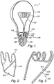
- FIG. 1 With reference to Figure 1 , there is shown a lighting device in accordance with an embodiment of the present invention.
- Figure 1 shows a lighting device 1 comprising a first light emitting element 101 and a second light emitting element 102.
- the first light emitting element 101 is optically coupled to a light guide 110 having an out-coupling surface 111.
- the optical coupling can be provided e.g. via an optical element (not shown) arranged between the first light emitting element 101 and the light guide 110 or by linking the first light emitting element 101 directly to the light guide 110, as shown in Figure 1 .
- the lighting device may be provided with additional first light emitting elements being optically coupled to the light guide 110.
- one first light emitting element may be coupled to a first end of the light guide 110 and another first light emitting element may be coupled to another end of the light guide 110 (opposite to the first end).
- the lighting device may be provided with additional second light emitting elements 102 for providing functional lighting.
- the first light emitting element 101 and/or the second light emitting element 102 may for instance be light emitting diodes, LEDs, such as e.g. laser LEDs.
- LEDs such as e.g. laser LEDs.
- an amber colored LED providing a warm light
- An alternative is to provide e.g. phosphor (or any other wavelength converting material) on top of the light guide (i.e. at the out-coupling surface of the lightguide) and select a phosphor providing a warm colored light.
- the first light emitting element 101 may comprise a red LED, a green LED and a blue LED, thereby together providing a white light, which may be modulated into different colors by controlling the red, green and blue LED.
- an LED of a colder color (which may be more efficient), such as white, may be used as the second light emitting element 102, thereby providing light being suitable for functional lighting.
- the second light emitting element 102 may comprise a red LED, a green LED and a blue LED, thereby together providing a white light, which may be modulated into different colors by controlling the red, green and blue LED.
- the invention is not limited to such color configuration, the light emitting elements 101, 102 in the lighting device may be of any desired color.
- the light guide 110 may comprise an optical fiber (like an optical wave guide) made of a suitable material such as plastics or glass-fiber.
- a suitable material such as plastics or glass-fiber.
- the use glass-fiber material is advantageous because of its optical quality and material characteristics (e.g. sensitivity to heat).
- the optical fiber may be of a shorter or longer length allowing a simple or more complex design.
- the optical fiber may be spirally wound in order to resemble a traditional retro-filament.
- the out-coupling of light from the out-coupling surface 111 of the light guide 110 may be achieved (and/or enhanced) in different ways. Some of the light may be out-coupled due to curvatures of the light guide 110. Moreover, the light guide 110 may be provided with diffusing means for out-coupling the light. In general, any optical distortion added to the light guide will provide out-coupling of light.
- the diffusing means may be provided e.g. by making the out-coupling surface 111 rough (e.g. by sand-blasting, scratching, or molding in a texture in the surface), or by providing indents or small protrusions in the out-coupling surface 111. Further, particles (e.g. white paint) and/or vacuum/gas bubbles (e.g. created by local laser heating) may be provided on or inside the light guide such that light is scattered out of the light guide.
- particles e.g. white paint
- vacuum/gas bubbles e.g. created by local laser heating
- the light guide 110 may comprise at least one connecting port 112 to which the first light emitting element 101 may be optically coupled.
- the present embodiment is advantageous in that it allows a great part of the light emitted from the first light emitting element 101 to be received and out-coupled by the light guide 110, thereby serving a decorative purpose, and still a great part of the light emitted from the second light emitting element 102 provides an illumination without unnecessary considerable energy-losses in any light guide.
- some (i.e. a relatively small part) of the light emitted from the second light emitting element(s) 102 may be coupled into the light guide 110 via the out-coupling surface 111, and thus, coupled out again via the out-coupling surface 111, thereby contributing to the illumination out of the light guide 110.
- Figure 2 shows a light guide in the form of a light guide plate 210 being optically coupled to a first light emitting element 201. Some of the light emitted from the first light emitting element 201 is coupled out via an edge 211 which may be curved (and optionally rough), thereby resulting in the appearance of a filament such as in a traditional light bulbs. Further, light may be coupled out via diffusing means provided inside the light guide plate 210 or on the surface of the light guide plate 210.
- the light guide may be designed in any desired three-dimensional shape, such as a spherical or prismatic shape.
- the diffusing means may be provided at any desired position in or on the light guide.
- the diffusing means may form a pattern (such as a filament-resembling pattern).
- Figure 3 shows a light guide 320 in the form of a continuous optical element 323 in which a string of a plurality of LEDs 321 is arranged.
- the LEDs 321 may be mounted on a small flexible PCB (printed circuit board) 322 with the continuous optical element 323 on top of it (or encapsulating it).
- PCB printed circuit board
- the lighting device 1 comprises an envelope 130 encapsulating the first light emitting element 101, the second light emitting element 102 and the light guide110.
- the envelope 130 is transparent (or at least semi-transparent) such that the light guide 110 is visible for providing a decorative effect.
- the envelope 130 may be formed as a bulb resembling a traditional incandescent light bulb.
- the lighting device 1 may further comprise a base 140 at which the first light emitting element 101 and the second light emitting element 102 are arranged.
- the base 140 may comprise a bayonet base or a screw base 141 (e.g.
- the base 140 may further comprise a heat-sink 142 for cooling the light emitting diodes 101, 102.
- the light emitting elements 101, 102 may be arranged such that an upper portion of the heat-sink 142 (or an upper portion of the base 140) hides the light emitting elements 101, 102 (as shown in Figure 1 ) for reducing the risk of direct view of them.
- the inside of the upper portion of the heat-sink 142 may be reflective such that all (or at least almost all) light emitted from the light emitting elements 101, 102 can be output from the lighting device.
- the lighting device may further comprise a diffusing/scattering element (not shown) in form of a plate on top of the second light emitting elements 102.
- a diffusing/scattering element (not shown) in form of a plate on top of the second light emitting elements 102.
- such plate may be arranged on top of the base 140.
- the plate may be provided with a hole where light emitted from the first light emitting element 101 may go through to be coupled into the light guide 110.
- the lighting device 1 may further comprise electronic driving means 150 provided with a power supply for converting the mains voltage supply into an output signal suitable for driving the light emitting elements 101, 102.
- the electric driving means 150 may further comprise an electronic circuitry configured to control the light intensity of the first light emitting element 101 and/or the second light emitting element 102 such that the light intensity of the second light emitting element 102 is adjustable relative to the light intensity of the first light emitting element 101.
- the electronic circuitry may be configured to slightly modulate the brightness (or color) of the first light emitting element 101, or to sequentially switch on and off the first light emitting element 101, for providing a flame and flickering effect of the light guide 110.
- the electronic circuitry may further contain a transfer function for correlating an input signal (such as input current or input voltage) with a light output and/or an emission color of the first and second light emitting elements.
- the electric driving means 150 may be controlled by a remote control unit, by buttons on the base 140 or by any other type of user interface.
- the first light emitting element 101 and/or the second light emitting element 102 may be dimmable.
- the lighting device supports traditional incandescent light dimmers such that the light emitting elements can operate in a dimmed mode.
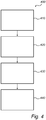
- Figure 4 shows the general outline of a method 400 of manufacturing a lighting device.
- the method comprises a step 410 of providing a first light emitting element, a step 420 of providing a light guide having an out-coupling surface, and a step 430 of optically coupling the first light emitting element to the light guide.
- the method 400 comprises a step 440 of providing a second light emitting element dedicated for direct illumination from the lighting device.
- additional light guides with associated first light emitting elements may be provided in the lighting device.
- the lighting device can be applied in standalone retro-fit incandescent bulb replacements as well as in dedicated new luminaries.
- the lighting device is not limited to be designed as a conventional light bulb. It can also be designed e.g. as a tubular-shaped lamp with connectors at both ends of the tube.
Description
- The present invention generally relates to the field of lighting devices.
- Traditional incandescent light bulbs are available in various designs such as plain functional bulbs with different glass finishes (e.g. transparent, diffuse or colored) and decorative bulbs with complex filaments, wherein the filament itself serves a decorative purpose. However, due to demands on power saving in lighting devices, driven by eco awareness and legislation, traditional incandescent light bulbs are being replaced by more power efficient light sources such as fluorescent lamps and LED (light emitting diode) lamps. Such conventional eco-friendly lamps do not provide the same various designs as traditional incandescent light bulbs.
- A solution of how to provide a lighting device resembling a carbon filament lamp is disclosed in
WO 2006/035349 . The document shows a lighting device comprising a solid state light source optically coupled to an optical fiber having an out-coupling surface. A drawback with such a lighting device is that it does not provide a sufficiently energy-efficient functional lighting (such as e.g. general lighting or task lighting). - Thus, there is a need for providing alternatives and/or new devices that would overcome, or at least alleviate or mitigate, at least some of the above mentioned drawbacks. It is with respect to the above considerations that the present invention has been made. An object of the present invention is to provide an improved alternative to the above mentioned technique and prior art.
- More specifically, it is an object of the present invention to provide a lighting device enabling both decorative lighting and functional lighting with improved efficiency. It is also an object of the present invention to provide a method of manufacturing such a lighting device.
- These and other objects of the present invention are achieved by means of a lighting device and a method of manufacturing the lighting device having the features defined in the independent claims. Preferable embodiments of the invention are characterized by the dependent claims.
- Hence, according to a first aspect of the present invention, a lighting device according to
claim 1 is provided. - Further, according to a second aspect of the invention, a method of manufacturing a lighting device according to claim 13 is provided.
- The basic idea of the invention is that the light emitted from the first light emitting element is emitted out of the lighting device via the light guide and the light emitted from the second light emitting element is emitted out of the lighting device directly from the second light emitting element. As a result, decorative lighting is provided by the light guide and the first light emitting element, and a direct functional illumination is provided by the second light emitting element.
- In this respect, with the term "direct illumination" it is meant that most of, or at least a considerable part of the light emitted from the second light emitting element is emitted from the lighting device without passing a light guide. The inventor has realized that the lighting device according to prior art suffers from energy-losses when the light emitted from the solid state light source is coupled into the optical fiber and then out again. Hence, the lighting device according to prior art may be improved with respect to functional lighting (such as e.g. general lighting or task lighting). Functional lighting may be defined as a type of lighting wherein it is desirable to output from the lighting device as much of the light emitted from the solid state light source as possible.
- The present invention is advantageous in that the lighting device provides both a decorative appearance (look) and functional illumination, and is still energy-efficient since the light emitted from the second light emitting element is directly emitted from the second light emitting element without unnecessary energy-loss.
- Further, the present invention is advantageous in that a double functionality (decorative lighting and functional lighting) is provided within a single lighting device, enabling an extended field of use since the lighting device may be used both in a decorative purpose and e.g. for general lighting or task lighting.
- According to the present invention, the illumination from the lighting device via the light guide and the first light emitting element is dedicated to a first type of lighting. Further, illumination from the lighting device from the second light emitting element without any light guide is dedicated to a second type of lighting.
- Accordingly, the first type of lighting and the second type of lighting are functionally and structurally separated such that each type of lighting can be optimized in terms of energy-efficiency.
- According to the present invention, the first light emitting element is dedicated to decorative lighting via the light guide, and the second light emitting element is dedicated to functional lighting (without any light guide).
- According to an embodiment of the present invention, the light intensity of the second light emitting element may be adjustable relative to the light intensity of the first light emitting element. Preferably the light intensity of the second light emitting element may be adjustable relative to the light intensity of the first light emitting element in response to an input signal to the lighting device. The input signal may be received at the lighting device from a dimmer connected to the lighting device (wherein the actual receiver of the dim signal is on the mains voltage). Alternatively, the input signal may be received at e.g. a low voltage circuitry of the lighting device (further described below) via a remote control (operated by a user of the lighting device). Preferably, a transfer function may be used such that the input voltage is correlated to a specific relationship or ratio between the intensity of the first light emitting element and the intensity of the second light emitting element. The present embodiment is advantageous in that it provides at least two different operation modes of the lighting device, a decorative mode for which the light intensity of the second light emitting element is lower than the light intensity of the first light emitting element and a functional mode for which the light intensity of the second light emitting element is higher than the light intensity of the first light emitting element. In other words, the light guide will become more visible and stand for a greater part of the total light-output from the lighting device when the light intensity of the second light emitting element is lowered in the decorative mode compared to when the lighting device is in the functional mode. In the functional mode, the light intensity of the second light emitting element will dominate the total light-output from the lighting device.
- In an embodiment of the present invention, at least one of the second light emitting element and the first light emitting element may be dimmable, which is advantageous in that it provides a step-less transition between the two above-mentioned operation modes of the lighting device. Moreover, the first light emitting element and the second light emitting element may be simultaneously and/or separately (individually) dimmed. For example, when the light intensity of the first light emitting element is increased, simultaneously, also the light intensity of the second light emitting element may be increased. Such a kind of regulation may be implemented using a single dimming device common to all light emitting elements (making the lighting device relatively technically simple). Hence, when both the first light emitting element and the second light emitting element are operated at a low dimmed level (i.e. at a low light intensity) the total light-output from the lighting device is low, thereby rendering visible the light guide which may provide a decorative appearance. In contrast, when the light emitting elements are driven at a high power level (i.e. at a high light intensity) the total light-output from the lighting device is high, thereby providing a functional lighting. It will be appreciated that such a kind of regulation with a common dimmer resembles the function of a traditional incandescent lighting device.
- According to another example, wherein the light emitting elements are individually dimmed, the light intensity of the first light emitting element is increased while the light intensity of the second light emitting element is decreased. The above-mentioned effects (for resemblance to the function of a traditional incandescent lighting device) may be achieved and even enhanced, when the first light emitting element and the second light emitting element have different light intensities.
- According to an embodiment of the invention, a wavelength (color) of the light emitted from the first light emitting element is adjustable, preferably in response to an input signal to the lighting device. For example, the color of the first light emitting element may be adjusted to be red/amber in the decorative mode and yellow/white in the functional mode.
- In an embodiment of the invention, the input signal to the lighting device may be a current or a voltage supplied to the lighting device. Further, lighting device may comprise a circuitry with a transfer function correlating the input signal with a light-output and/or the light color of the first and second light emitting element. As an illustrating example, for a low input signal (such as in a dimmed traditional incandescent lamp), the first light emitting element may provide a red/amber color and have a relatively low light intensity, while the light intensity of the second light emitting element may preferably be turned off. The stronger the input signal is, the more the first light emitting element may become yellow/white (and the more the light output from the first light emitting element is increased) and, at some threshold value of the input signal, the second light emitting element switches on and light-output is slowly increased.
- According to further embodiments of the present invention, the light guide may comprise an optical fiber, which is advantageous in that the optical fiber may resemble a carbon-filament. Alternately, the light guide may comprise a light guide plate, which may be designed in any desired way. For example, the light guide may be designed in any three-dimensional shape.
- According to an embodiment of the present invention, the light guide may be provided with diffusing means for out-coupling light. The diffusing means enhances the out-coupling of the light guided into the light guide and thus, renders the light guide more clearly visible. In an embodiment of the invention, the structure of the out-coupling surface (e.g. the roughness of the surface) may be selected to adjust the scattering of the light. Further, the light guide may comprise (scattering or diffusing) particles and/or vacuum/gas bubbles for out-coupling light. In other words, distortions of the optical characteristics of the light guide are provided for scattering out some of the light. These distortions may be located on the surface/edge of the light guide and/or inside of the light guide. Generally, any optical distortion resulting in a change of the internal light angles may result in that part of the light is coupled out of the light guide. Distortions in a 3D-shaped light guide may for example be obtained by local laser heating.
- According to an embodiment of the present invention, at least one of the first light emitting element and the second light emitting element may comprise at least one light emitting diode (LED), which is advantageous in that LEDs are high-efficient point-like light sources available in several different colors, thereby allowing various designs of the lighting device. Further, the LED may be a laser-LED, which is advantageous in that it improves the coupling of light to the light guide.
- According to an embodiment of the invention, a string of a plurality of light emitting diodes may be provided in the light guide.
- According to of the present invention, the lighting device comprises an envelope encapsulating the first light emitting element, the second light emitting element and the light guide, which is advantageous in that the light emitting elements and the light guide will be protected against damage and dust. Additionally, the lighting device will resemble a traditional incandescent light bulb.
- According to an embodiment of the present invention, the lighting device may further comprise a base at which the first light emitting element and the second light emitting element are arranged.
- Optionally, the lighting device may further comprise a diffusing/scattering element arranged on top of the second light emitting element e.g. in the form of a plate covering the second light emitting element(s). Such a diffusing/scattering element is advantageous in that an individual light emitting element will be less visible and provide a more even light distribution than without a diffusing/scattering element.
- Further objectives of, features of, and advantages with, the present invention will become apparent when studying the following detailed disclosure, the drawings and the appended claims. Those skilled in the art realize that different features of the present invention can be combined to create embodiments other than those described in the following. In particular, it will be appreciated that the various embodiments described for the lighting device are all combinable with the method as defined in accordance with the second aspect of the present invention.
- The above, as well as additional objects, features and advantages of the present invention, will be better understood through the following illustrative and nonlimiting detailed description of preferred embodiments of the present invention, with reference to the appended drawings, in which:
-
Figure 1 shows a lighting device according to an embodiment of the present invention; -
Figure 2 shows a light guide according to an embodiment of the present invention; -
Figure 3 shows a light guide according to another embodiment of the present invention; and -
Figure 4 is a general outline of a method of manufacturing a lighting device according to an embodiment of the present invention. - With reference to
Figure 1 , there is shown a lighting device in accordance with an embodiment of the present invention. -
Figure 1 shows alighting device 1 comprising a firstlight emitting element 101 and a secondlight emitting element 102. The firstlight emitting element 101 is optically coupled to alight guide 110 having an out-coupling surface 111. The optical coupling can be provided e.g. via an optical element (not shown) arranged between the firstlight emitting element 101 and thelight guide 110 or by linking the firstlight emitting element 101 directly to thelight guide 110, as shown inFigure 1 . - Optionally, the lighting device may be provided with additional first light emitting elements being optically coupled to the
light guide 110. For example, one first light emitting element may be coupled to a first end of thelight guide 110 and another first light emitting element may be coupled to another end of the light guide 110 (opposite to the first end). - Further, the lighting device may be provided with additional second
light emitting elements 102 for providing functional lighting. - The first
light emitting element 101 and/or the secondlight emitting element 102 may for instance be light emitting diodes, LEDs, such as e.g. laser LEDs. For example, an amber colored LED, providing a warm light, may be used as the firstlight emitting element 101, thereby resulting in a light guide resembling a warm glowing filament (when the first light emitting element is activated/on). An alternative is to provide e.g. phosphor (or any other wavelength converting material) on top of the light guide (i.e. at the out-coupling surface of the lightguide) and select a phosphor providing a warm colored light. According to another example, the firstlight emitting element 101 may comprise a red LED, a green LED and a blue LED, thereby together providing a white light, which may be modulated into different colors by controlling the red, green and blue LED. - Further, an LED of a colder color (which may be more efficient), such as white, may be used as the second
light emitting element 102, thereby providing light being suitable for functional lighting. According to another example, the secondlight emitting element 102 may comprise a red LED, a green LED and a blue LED, thereby together providing a white light, which may be modulated into different colors by controlling the red, green and blue LED. However, it will be appreciated that the invention is not limited to such color configuration, thelight emitting elements - The
light guide 110 may comprise an optical fiber (like an optical wave guide) made of a suitable material such as plastics or glass-fiber. The use glass-fiber material is advantageous because of its optical quality and material characteristics (e.g. sensitivity to heat). The optical fiber may be of a shorter or longer length allowing a simple or more complex design. For example, the optical fiber may be spirally wound in order to resemble a traditional retro-filament. - The out-coupling of light from the out-
coupling surface 111 of thelight guide 110 may be achieved (and/or enhanced) in different ways. Some of the light may be out-coupled due to curvatures of thelight guide 110. Moreover, thelight guide 110 may be provided with diffusing means for out-coupling the light. In general, any optical distortion added to the light guide will provide out-coupling of light. The diffusing means may be provided e.g. by making the out-coupling surface 111 rough (e.g. by sand-blasting, scratching, or molding in a texture in the surface), or by providing indents or small protrusions in the out-coupling surface 111. Further, particles (e.g. white paint) and/or vacuum/gas bubbles (e.g. created by local laser heating) may be provided on or inside the light guide such that light is scattered out of the light guide. - According to an embodiment of the present invention, the
light guide 110 may comprise at least one connectingport 112 to which the firstlight emitting element 101 may be optically coupled. The present embodiment is advantageous in that it allows a great part of the light emitted from the firstlight emitting element 101 to be received and out-coupled by thelight guide 110, thereby serving a decorative purpose, and still a great part of the light emitted from the secondlight emitting element 102 provides an illumination without unnecessary considerable energy-losses in any light guide. - However, some (i.e. a relatively small part) of the light emitted from the second light emitting element(s) 102 may be coupled into the
light guide 110 via the out-coupling surface 111, and thus, coupled out again via the out-coupling surface 111, thereby contributing to the illumination out of thelight guide 110. - With reference to
Figure 2 , there is shown an alternative design of a light guide according to an embodiment of the invention.Figure 2 shows a light guide in the form of alight guide plate 210 being optically coupled to a firstlight emitting element 201. Some of the light emitted from the firstlight emitting element 201 is coupled out via anedge 211 which may be curved (and optionally rough), thereby resulting in the appearance of a filament such as in a traditional light bulbs. Further, light may be coupled out via diffusing means provided inside thelight guide plate 210 or on the surface of thelight guide plate 210. - It will be appreciated that the light guide may be designed in any desired three-dimensional shape, such as a spherical or prismatic shape. Further, the diffusing means may be provided at any desired position in or on the light guide. For example, the diffusing means may form a pattern (such as a filament-resembling pattern).
- With reference to
Figure 3 , there is shown another design of a light guide according to yet another embodiment of the invention.Figure 3 shows alight guide 320 in the form of a continuousoptical element 323 in which a string of a plurality ofLEDs 321 is arranged. TheLEDs 321 may be mounted on a small flexible PCB (printed circuit board) 322 with the continuousoptical element 323 on top of it (or encapsulating it). - Turning again back to
Figure 1 , further embodiments of the invention will be described. Thelighting device 1 comprises anenvelope 130 encapsulating the firstlight emitting element 101, the secondlight emitting element 102 and the light guide110. Preferably, theenvelope 130 is transparent (or at least semi-transparent) such that thelight guide 110 is visible for providing a decorative effect. Further, theenvelope 130 may be formed as a bulb resembling a traditional incandescent light bulb. Thelighting device 1 may further comprise a base 140 at which the firstlight emitting element 101 and the secondlight emitting element 102 are arranged. The base 140 may comprise a bayonet base or a screw base 141 (e.g. of the type E14, E26 or E27), which is advantageous in that the lighting device can be fitted in conventional lamp fittings and used as a replacement for a traditional incandescent light bulb (retro-fitting). The base 140 may further comprise a heat-sink 142 for cooling thelight emitting diodes light emitting elements light emitting elements 101, 102 (as shown inFigure 1 ) for reducing the risk of direct view of them. Further, the inside of the upper portion of the heat-sink 142 may be reflective such that all (or at least almost all) light emitted from thelight emitting elements - The lighting device may further comprise a diffusing/scattering element (not shown) in form of a plate on top of the second
light emitting elements 102. For example, such plate may be arranged on top of thebase 140. The plate may be provided with a hole where light emitted from the firstlight emitting element 101 may go through to be coupled into thelight guide 110. - The
lighting device 1 may further comprise electronic driving means 150 provided with a power supply for converting the mains voltage supply into an output signal suitable for driving thelight emitting elements light emitting element 101 and/or the secondlight emitting element 102 such that the light intensity of the secondlight emitting element 102 is adjustable relative to the light intensity of the firstlight emitting element 101. Further, the electronic circuitry may be configured to slightly modulate the brightness (or color) of the firstlight emitting element 101, or to sequentially switch on and off the firstlight emitting element 101, for providing a flame and flickering effect of thelight guide 110. The electronic circuitry may further contain a transfer function for correlating an input signal (such as input current or input voltage) with a light output and/or an emission color of the first and second light emitting elements. The electric driving means 150 may be controlled by a remote control unit, by buttons on the base 140 or by any other type of user interface. - In an embodiment of the invention, the first
light emitting element 101 and/or the secondlight emitting element 102 may be dimmable. In an embodiment of the invention, the lighting device supports traditional incandescent light dimmers such that the light emitting elements can operate in a dimmed mode. - With reference to
Figure 4 , a method of manufacturing a lighting device according to an embodiment of the present invention will be described.Figure 4 shows the general outline of amethod 400 of manufacturing a lighting device. The method comprises astep 410 of providing a first light emitting element, astep 420 of providing a light guide having an out-coupling surface, and astep 430 of optically coupling the first light emitting element to the light guide. Further, themethod 400 comprises astep 440 of providing a second light emitting element dedicated for direct illumination from the lighting device. - While specific embodiments have been described, the skilled person will understand that various modifications and alterations are conceivable within the scope as defined in the appended claims.
- For example, additional light guides with associated first light emitting elements may be provided in the lighting device. Further, the lighting device can be applied in standalone retro-fit incandescent bulb replacements as well as in dedicated new luminaries. Moreover, the lighting device is not limited to be designed as a conventional light bulb. It can also be designed e.g. as a tubular-shaped lamp with connectors at both ends of the tube.
Claims (13)
- A lighting device for providing decorative lighting comprising:a first light emitting element (101) being optically coupled to a light guide (110) having an out-coupling surface (111) for decorative illumination via the light guide;characterized by a second light emitting element (102) dedicated for providing a further direct functional illumination from the lighting device, andan envelope (130) encapsulating said first light emitting element (101), said light guide (110), and said second light emitting element (102).
- A lighting device as defined in claim 1, wherein the light intensity of the second light emitting element is adjustable relative to the light intensity of the first light emitting element, preferably in response to an input signal to the lighting device.
- A lighting device as defined in any one of the preceding claims, wherein at least one of the second light emitting element and the first light emitting element is dimmable.
- A lighting device as defined in any one of the preceding claims, wherein a wavelength (color) of the light emitted from the first light emitting element is adjustable, preferably in response to an input signal to the lighting device.
- A lighting device as defined in any one of the preceding claims, wherein the light guide comprises an optical fiber, a light guide plate (210), or a three-dimensionally shaped light guide.
- A lighting device as defined in any one of the preceding claims, wherein the light guide is provided with diffusing means for out-coupling light.
- A lighting device as defined in any one of the preceding claims, wherein the structure of the out-coupling surface is selected to adjust scattering of the light.
- A lighting device as defined in any one of the preceding claims, wherein the light guide comprises particles and/or vacuum/gas bubbles for out-coupling light.
- A lighting device as defined in any one of the preceding claims, wherein at least one of the first light emitting element and the second light emitting element comprises at least one light emitting diode.
- A lighting device as defined in any one of the preceding claims, wherein a string of a plurality of light emitting diodes (321) is provided in the light guide (320).
- A lighting device as defined in any one of the preceding claims, further comprising a base (140) at which the first light emitting element and the second light emitting element are arranged.
- A lighting device as defined claim 11, characterized in that said base (140) comprises a bayonet or screw base (141) for retro-fitting a traditional incandescent light bulb.
- A method of manufacturing a lighting device for providing decorative lighting, the method comprising the steps of:providing a first light emitting element (101);providing a light guide (110) having an out-coupling surface for decorative illumination via the light guide;optically coupling the first light emitting element to the light guide;providing a second light emitting element (102) dedicated for direct functional illumination from the lighting device; andencapsulating said first light emitting element (101), said light guide (110), and said second light emitting element (102) in an envelope (130).
Priority Applications (5)
| Application Number | Priority Date | Filing Date | Title |
|---|---|---|---|
| EP11804814.9A EP2655956B1 (en) | 2010-12-22 | 2011-12-09 | Lighting device and method for manufacturing a lighting device |
| EP23171105.2A EP4235015A3 (en) | 2010-12-22 | 2011-12-09 | Lighting device and method for manufacturing a lighting device |
| EP19213280.1A EP3653924A1 (en) | 2010-12-22 | 2011-12-09 | Lighting device and method for manufacturing a lighting device |
| EP23171110.2A EP4235016A3 (en) | 2010-12-22 | 2011-12-09 | Lighting device and method for manufacturing a lighting device |
| PL11804814T PL2655956T3 (en) | 2010-12-22 | 2011-12-09 | Lighting device and method for manufacturing a lighting device |
Applications Claiming Priority (3)
| Application Number | Priority Date | Filing Date | Title |
|---|---|---|---|
| EP10196396 | 2010-12-22 | ||
| EP11804814.9A EP2655956B1 (en) | 2010-12-22 | 2011-12-09 | Lighting device and method for manufacturing a lighting device |
| PCT/IB2011/055565 WO2012085736A1 (en) | 2010-12-22 | 2011-12-09 | Lighting device and method for manufacturing a lighting device |
Related Child Applications (4)
| Application Number | Title | Priority Date | Filing Date |
|---|---|---|---|
| EP19213280.1A Division EP3653924A1 (en) | 2010-12-22 | 2011-12-09 | Lighting device and method for manufacturing a lighting device |
| EP19213280.1A Division-Into EP3653924A1 (en) | 2010-12-22 | 2011-12-09 | Lighting device and method for manufacturing a lighting device |
| EP23171105.2A Division EP4235015A3 (en) | 2010-12-22 | 2011-12-09 | Lighting device and method for manufacturing a lighting device |
| EP23171110.2A Division EP4235016A3 (en) | 2010-12-22 | 2011-12-09 | Lighting device and method for manufacturing a lighting device |
Publications (2)
| Publication Number | Publication Date |
|---|---|
| EP2655956A1 EP2655956A1 (en) | 2013-10-30 |
| EP2655956B1 true EP2655956B1 (en) | 2020-07-29 |
Family
ID=45444669
Family Applications (4)
| Application Number | Title | Priority Date | Filing Date |
|---|---|---|---|
| EP23171105.2A Pending EP4235015A3 (en) | 2010-12-22 | 2011-12-09 | Lighting device and method for manufacturing a lighting device |
| EP19213280.1A Pending EP3653924A1 (en) | 2010-12-22 | 2011-12-09 | Lighting device and method for manufacturing a lighting device |
| EP23171110.2A Pending EP4235016A3 (en) | 2010-12-22 | 2011-12-09 | Lighting device and method for manufacturing a lighting device |
| EP11804814.9A Active EP2655956B1 (en) | 2010-12-22 | 2011-12-09 | Lighting device and method for manufacturing a lighting device |
Family Applications Before (3)
| Application Number | Title | Priority Date | Filing Date |
|---|---|---|---|
| EP23171105.2A Pending EP4235015A3 (en) | 2010-12-22 | 2011-12-09 | Lighting device and method for manufacturing a lighting device |
| EP19213280.1A Pending EP3653924A1 (en) | 2010-12-22 | 2011-12-09 | Lighting device and method for manufacturing a lighting device |
| EP23171110.2A Pending EP4235016A3 (en) | 2010-12-22 | 2011-12-09 | Lighting device and method for manufacturing a lighting device |
Country Status (10)
| Country | Link |
|---|---|
| US (4) | US9234635B2 (en) |
| EP (4) | EP4235015A3 (en) |
| JP (1) | JP5952828B2 (en) |
| CN (2) | CN105864664B (en) |
| BR (1) | BR112013015643A2 (en) |
| ES (1) | ES2819056T3 (en) |
| PL (1) | PL2655956T3 (en) |
| RU (1) | RU2614135C2 (en) |
| TW (1) | TWI601911B (en) |
| WO (1) | WO2012085736A1 (en) |
Families Citing this family (64)
| Publication number | Priority date | Publication date | Assignee | Title |
|---|---|---|---|---|
| US10655792B2 (en) * | 2014-09-28 | 2020-05-19 | Zhejiang Super Lighting Electric Appliance Co., Ltd. | LED bulb lamp |
| US10677396B2 (en) | 2006-07-22 | 2020-06-09 | Jiaxing Super Lighting Electric Appliance Co., Ltd | LED light bulb with symmetrical filament |
| US10487987B2 (en) | 2015-08-17 | 2019-11-26 | Zhejiang Super Lighting Electric Appliance Co., Ltd. | LED filament |
| US9995474B2 (en) | 2015-06-10 | 2018-06-12 | Jiaxing Super Lighting Electric Appliance Co., Ltd. | LED filament, LED filament assembly and LED bulb |
| US10544905B2 (en) * | 2014-09-28 | 2020-01-28 | Zhejiang Super Lighting Electric Appliance Co., Ltd. | LED bulb lamp |
| US10240724B2 (en) | 2015-08-17 | 2019-03-26 | Zhejiang Super Lighting Electric Appliance Co., Ltd. | LED filament |
| US10473271B2 (en) | 2015-08-17 | 2019-11-12 | Zhejiang Super Lighting Electric Appliance Co., Ltd. | LED filament module and LED light bulb |
| US11131431B2 (en) | 2014-09-28 | 2021-09-28 | Jiaxing Super Lighting Electric Appliance Co., Ltd | LED tube lamp |
| CN103975189A (en) * | 2011-12-14 | 2014-08-06 | 通用电气照明解决方案有限责任公司 | Side-emitting guidepipe technology on led lamp to make filament effect |
| US9528689B2 (en) * | 2013-03-13 | 2016-12-27 | Palo Alto Research Center Incorporated | LED lighting device with cured structural support |
| DE102013209852A1 (en) * | 2013-05-27 | 2014-11-27 | Osram Gmbh | lamp |
| US20140355292A1 (en) * | 2013-05-30 | 2014-12-04 | Gabriel Krause | Fiber Optic Filament Lamp |
| TWI599745B (en) * | 2013-09-11 | 2017-09-21 | 晶元光電股份有限公司 | Flexible led assembly and led light bulb |
| NL2011488C2 (en) * | 2013-09-23 | 2015-03-24 | Giga Groep B V | Light bulb. |
| WO2015081804A1 (en) * | 2013-12-02 | 2015-06-11 | 张晓峰 | Spiral led filament and light bulb using spiral led filament |
| CN104747926B (en) * | 2013-12-26 | 2018-01-19 | 上海顿格电子贸易有限公司 | A kind of lumination of light emitting diode bulb and its installation method |
| US20170051877A1 (en) * | 2014-02-24 | 2017-02-23 | Philips Lighting Holding B.V. | Lamp assembly |
| CN108613029A (en) * | 2014-03-13 | 2018-10-02 | 飞利浦照明控股有限公司 | Filament for lighting device |
| US9488767B2 (en) * | 2014-08-05 | 2016-11-08 | Cree, Inc. | LED based lighting system |
| US20170284610A1 (en) * | 2014-08-18 | 2017-10-05 | Philips Lighting Holding B.V. | Lighting device with remote wavelength converting element |
| USD771302S1 (en) * | 2014-09-03 | 2016-11-08 | Big Trike Inc. | Illumination diffuser |
| US10784428B2 (en) | 2014-09-28 | 2020-09-22 | Zhejiang Super Lighting Electric Appliance Co., Ltd. | LED filament and LED light bulb |
| US11085591B2 (en) | 2014-09-28 | 2021-08-10 | Zhejiang Super Lighting Electric Appliance Co., Ltd | LED light bulb with curved filament |
| WO2016045630A1 (en) | 2014-09-28 | 2016-03-31 | Jiaxing Super Lighting Electric Appliance Co., Ltd | Led tube lamp |
| US10208898B2 (en) | 2015-04-29 | 2019-02-19 | Jiaxing Super Lighting Electric Appliance Co., Ltd. | LED tube lamp with operating modes compatible with electrical ballasts |
| US10845008B2 (en) | 2014-09-28 | 2020-11-24 | Zhejiang Super Lighting Electric Appliance Co., Ltd. | LED filament and LED light bulb |
| US11686436B2 (en) | 2014-09-28 | 2023-06-27 | Zhejiang Super Lighting Electric Appliance Co., Ltd | LED filament and light bulb using LED filament |
| US11543083B2 (en) | 2014-09-28 | 2023-01-03 | Zhejiang Super Lighting Electric Appliance Co., Ltd | LED filament and LED light bulb |
| US11690148B2 (en) | 2014-09-28 | 2023-06-27 | Zhejiang Super Lighting Electric Appliance Co., Ltd. | LED filament and LED light bulb |
| US11421827B2 (en) | 2015-06-19 | 2022-08-23 | Zhejiang Super Lighting Electric Appliance Co., Ltd | LED filament and LED light bulb |
| US11525547B2 (en) | 2014-09-28 | 2022-12-13 | Zhejiang Super Lighting Electric Appliance Co., Ltd | LED light bulb with curved filament |
| US10560989B2 (en) | 2014-09-28 | 2020-02-11 | Jiaxing Super Lighting Electric Appliance Co., Ltd | LED tube lamp |
| US11073248B2 (en) | 2014-09-28 | 2021-07-27 | Zhejiang Super Lighting Electric Appliance Co., Ltd. | LED bulb lamp |
| US10976009B2 (en) | 2014-09-28 | 2021-04-13 | Zhejiang Super Lighting Electric Appliance Co., Ltd | LED filament light bulb |
| US11028970B2 (en) | 2014-09-28 | 2021-06-08 | Zhejiang Super Lighting Electric Appliance Co., Ltd | LED filament light bulb having organosilicon-modified polyimide resin composition filament base layer |
| US11028973B2 (en) | 2015-03-10 | 2021-06-08 | Jiaxing Super Lighting Electric Appliance Co., Ltd. | Led tube lamp |
| US9897265B2 (en) | 2015-03-10 | 2018-02-20 | Jiaxing Super Lighting Electric Appliance Co., Ltd. | LED tube lamp having LED light strip |
| US11519565B2 (en) | 2015-03-10 | 2022-12-06 | Jiaxing Super Lighting Electric Appliance Co., Ltd | LED lamp and its power source module |
| CN106151934A (en) * | 2015-04-20 | 2016-11-23 | 葛兰菲照明有限公司 | Integrating illumination and the LED bulb of night-light function |
| CN104948956B (en) * | 2015-06-23 | 2017-03-15 | 南京邮电大学 | Conversion of white light fiber illumination device on a kind of multicomponent glass |
| GB2543139B (en) | 2015-08-17 | 2018-05-23 | Jiaxing Super Lighting Electric Appliance Co Ltd | LED light bulb and LED filament thereof |
| US10359152B2 (en) | 2015-08-17 | 2019-07-23 | Zhejiang Super Lighting Electric Appliance Co, Ltd | LED filament and LED light bulb |
| CN115539867A (en) * | 2015-09-24 | 2022-12-30 | 卡任特照明解决方案有限公司 | Lighting device |
| USD771303S1 (en) * | 2015-10-02 | 2016-11-08 | Big Trike Inc. | Illumination diffuser |
| US11035526B2 (en) | 2015-12-09 | 2021-06-15 | Jiaxing Super Lighting Electric Appliance Co., Ltd. | LED tube lamp |
| CN105508892A (en) * | 2016-01-19 | 2016-04-20 | 浙江鼎鑫工艺品有限公司 | LED simulated-filament bulb |
| US10415763B2 (en) | 2016-02-04 | 2019-09-17 | Osram Opto Semiconductors Gmbh | LED-filament and illuminant with LED-filament |
| EP3516845B1 (en) * | 2016-09-23 | 2020-11-11 | Signify Holding B.V. | Systems, methods, and apparatuses for distributing computational resources over a network of luminaires |
| JP7080253B2 (en) * | 2017-05-02 | 2022-06-03 | シグニファイ ホールディング ビー ヴィ | Lighting devices and lighting fixtures |
| US10260683B2 (en) | 2017-05-10 | 2019-04-16 | Cree, Inc. | Solid-state lamp with LED filaments having different CCT's |
| USD843637S1 (en) * | 2017-07-17 | 2019-03-19 | Salvage Electric | Decorative lamp |
| WO2019015763A1 (en) * | 2017-07-20 | 2019-01-24 | Explorentis | Led lamp with flexible led filament, and manufacturing method |
| US11067229B2 (en) * | 2017-08-25 | 2021-07-20 | Signify Holding B.V. | LED strip for indirect light emission |
| CN207471460U (en) * | 2017-10-27 | 2018-06-08 | 漳州立达信光电子科技有限公司 | Led lamp |
| US10790419B2 (en) | 2017-12-26 | 2020-09-29 | Jiaxing Super Lighting Electric Appliance Co., Ltd | LED filament and LED light bulb |
| WO2019129035A1 (en) | 2017-12-26 | 2019-07-04 | Jiaxing Super Lighting Electric Appliance Co., Ltd | Led filament and led light bulb |
| US11293597B2 (en) * | 2018-02-27 | 2022-04-05 | Signify Holding B.V. | LED filament lamp comprising a control unit |
| US10982048B2 (en) | 2018-04-17 | 2021-04-20 | Jiaxing Super Lighting Electric Appliance Co., Ltd | Organosilicon-modified polyimide resin composition and use thereof |
| US11187386B2 (en) | 2018-07-16 | 2021-11-30 | Signify Holding B.V. | LED filament lamp |
| WO2020207902A1 (en) * | 2019-04-11 | 2020-10-15 | Signify Holding B.V. | Solid state lamp |
| CN114651532A (en) | 2019-11-11 | 2022-06-21 | 昕诺飞控股有限公司 | LED filament lamp and method for manufacturing spiral LED filament |
| US11163100B2 (en) * | 2020-01-28 | 2021-11-02 | Lucifer Lighting Company | Light fixtures having waveguides and related methods |
| CN213333738U (en) * | 2020-08-31 | 2021-06-01 | 杭州杭科光电集团股份有限公司 | Color-controllable LED luminescent lamp |
| WO2023279559A1 (en) * | 2021-07-07 | 2023-01-12 | 杭州杭科光电集团股份有限公司 | Lamp |
Citations (1)
| Publication number | Priority date | Publication date | Assignee | Title |
|---|---|---|---|---|
| US20060152946A1 (en) * | 2004-07-06 | 2006-07-13 | Tseng-Lu Chien | Multiple light source night light |
Family Cites Families (66)
| Publication number | Priority date | Publication date | Assignee | Title |
|---|---|---|---|---|
| US5924784A (en) * | 1995-08-21 | 1999-07-20 | Chliwnyj; Alex | Microprocessor based simulated electronic flame |
| US6371637B1 (en) * | 1999-02-26 | 2002-04-16 | Radiantz, Inc. | Compact, flexible, LED array |
| TW455908B (en) | 1999-04-20 | 2001-09-21 | Koninkl Philips Electronics Nv | Lighting system |
| RU2185567C2 (en) * | 2000-02-14 | 2002-07-20 | ООО "Научно-технический центр ОПТОНИКА" | Light-emitting tube |
| RU2178588C1 (en) * | 2000-05-03 | 2002-01-20 | Марков Валерий Николаевич | Light panel |
| JP2002057371A (en) * | 2000-08-15 | 2002-02-22 | Hukuyo Denkyu Kk | Chain led light source structure |
| US6580228B1 (en) * | 2000-08-22 | 2003-06-17 | Light Sciences Corporation | Flexible substrate mounted solid-state light sources for use in line current lamp sockets |
| US6583550B2 (en) * | 2000-10-24 | 2003-06-24 | Toyoda Gosei Co., Ltd. | Fluorescent tube with light emitting diodes |
| US6592238B2 (en) * | 2001-01-31 | 2003-07-15 | Light Technologies, Inc. | Illumination device for simulation of neon lighting |
| WO2002062106A1 (en) * | 2001-02-02 | 2002-08-08 | Koninklijke Philips Electronics N.V. | Integrated light source |
| JP2002259830A (en) | 2001-02-28 | 2002-09-13 | Ricoh Co Ltd | Messaging system, method of providing message, and program |
| CN1640199B (en) * | 2002-01-07 | 2010-09-08 | 奥斯兰姆有限公司 | Lamp |
| EP1466505B1 (en) * | 2002-01-10 | 2012-08-01 | Osram Ag | Lamp |
| US20030147245A1 (en) * | 2002-02-01 | 2003-08-07 | Chen Ching Shui | Structure of a mini lamp |
| TW569980U (en) | 2002-10-09 | 2004-01-01 | Shr-Ling Chen | Jacklight for vehicle |
| US6853151B2 (en) * | 2002-11-19 | 2005-02-08 | Denovo Lighting, Llc | LED retrofit lamp |
| CN101915365B (en) * | 2003-05-05 | 2013-10-30 | 吉尔科有限公司 | LED-based light bulb |
| US7484860B2 (en) * | 2003-07-02 | 2009-02-03 | S.C. Johnson & Son, Inc. | Combination white light and colored LED light device with active ingredient emission |
| US20080106893A1 (en) * | 2004-07-02 | 2008-05-08 | S. C. Johnson & Son, Inc. | Lamp and bulb for illumination and ambiance lighting |
| US7476002B2 (en) * | 2003-07-02 | 2009-01-13 | S.C. Johnson & Son, Inc. | Color changing light devices with active ingredient and sound emission for mood enhancement |
| US7520635B2 (en) * | 2003-07-02 | 2009-04-21 | S.C. Johnson & Son, Inc. | Structures for color changing light devices |
| US20060238136A1 (en) | 2003-07-02 | 2006-10-26 | Johnson Iii H F | Lamp and bulb for illumination and ambiance lighting |
| US20050052885A1 (en) * | 2003-09-04 | 2005-03-10 | Amazing International Enterprise Limited | Structure of LED decoration lighting set |
| GB2408846A (en) * | 2003-12-02 | 2005-06-08 | Sung Tao Ho | LED lamp tube |
| MXPA06009907A (en) * | 2004-03-03 | 2006-12-14 | Johnson & Son Inc S C | Led light bulb with active ingredient emission. |
| PT3428506T (en) * | 2004-09-29 | 2020-07-10 | Signify Holding Bv | Lighting device |
| WO2006081707A1 (en) * | 2005-02-06 | 2006-08-10 | He Shan Lide Electronic Enterprise Company Ltd. | A new type light hose |
| US7375476B2 (en) * | 2005-04-08 | 2008-05-20 | S.C. Johnson & Son, Inc. | Lighting device having a circuit including a plurality of light emitting diodes, and methods of controlling and calibrating lighting devices |
| RU52318U1 (en) * | 2005-04-20 | 2006-03-27 | Михаил Владимирович Дубина | LIGHT SOURCE FOR SURGICAL LUMINAIRES |
| US7618175B1 (en) | 2005-07-08 | 2009-11-17 | Ilight Technologies, Inc. | LED lighting system with helical fiber filament |
| JP2007165811A (en) * | 2005-12-16 | 2007-06-28 | Nichia Chem Ind Ltd | Light emitting device |
| JP2007194132A (en) * | 2006-01-20 | 2007-08-02 | Fujifilm Holdings Corp | Lighting device |
| DE102006007134A1 (en) * | 2006-02-16 | 2007-08-23 | Hella Kgaa Hueck & Co. | Lighting device for use in motor vehicles, comprises housing, housing locking, translucent cover plate, and light sources, light-guiding element is partially connected with light diffuser |
| CN201032086Y (en) * | 2006-08-07 | 2008-03-05 | 陈锦伟 | Flexible optical fiber LED lamp strip |
| CA2751510C (en) * | 2006-09-12 | 2015-05-19 | Huizhou Light Engine Ltd. | Integrally formed single piece light emitting diode light wire |
| US8567992B2 (en) * | 2006-09-12 | 2013-10-29 | Huizhou Light Engine Ltd. | Integrally formed light emitting diode light wire and uses thereof |
| JP4989170B2 (en) * | 2006-09-20 | 2012-08-01 | オスラム・メルコ株式会社 | Compact LED lamp |
| US20080074867A1 (en) * | 2006-09-21 | 2008-03-27 | International Development Corp. | Solar powered outdoor flicker light |
| WO2008134056A1 (en) | 2007-04-26 | 2008-11-06 | Deak-Lam Inc. | Photon energy coversion structure |
| US7600897B2 (en) * | 2007-09-05 | 2009-10-13 | Hua-Hsin Tsai | Light emitting unit having light source inside a lamp tube with ceramic fins |
| US20090154167A1 (en) * | 2007-12-18 | 2009-06-18 | Jui-Li Lin | Multipurpose light source |
| CN101482237B (en) * | 2008-01-07 | 2010-09-29 | 安茂领 | LED flexible neon lamp strip |
| US7543957B1 (en) * | 2008-01-29 | 2009-06-09 | General Electric Company | Thermal management of LEDS integrated to compact fluorescent lamps |
| CN101940063A (en) * | 2008-02-06 | 2011-01-05 | Nxp股份有限公司 | Light color tunability |
| US8890401B2 (en) | 2008-02-25 | 2014-11-18 | Illumination Machines, Llc | Solid-state luminescent filament lamps |
| DE102008014317A1 (en) * | 2008-03-14 | 2009-09-17 | Zumtobel Lighting Gmbh | Luminaire with separate bulbs for direct lighting and indirect lighting |
| US20090251882A1 (en) | 2008-04-03 | 2009-10-08 | General Led, Inc. | Light-emitting diode illumination structures |
| US8360599B2 (en) * | 2008-05-23 | 2013-01-29 | Ilumisys, Inc. | Electric shock resistant L.E.D. based light |
| WO2010030336A1 (en) | 2008-09-15 | 2010-03-18 | Superbulbs, Inc. | Hybrid light bulbs |
| US20100097821A1 (en) * | 2008-10-16 | 2010-04-22 | Osram Sylvania, Inc. | Light emitting diode-based lamp having a volume scattering element |
| US7976206B2 (en) * | 2008-12-17 | 2011-07-12 | U-How Co., Ltd. | Structure of light bulb |
| KR20110104058A (en) | 2008-12-18 | 2011-09-21 | 코닌클리즈케 필립스 일렉트로닉스 엔.브이. | Light emitting device creating decorative light effects in a luminaire |
| FR2944854B1 (en) * | 2009-03-12 | 2016-07-22 | Blachere Iluminations | LAMP COMPRISING AN OVERLAPPED BULB OF A BULB INSIDE WHICH ARE PROVIDED WITH LIGHT DIODES |
| US20120000104A1 (en) * | 2009-03-17 | 2012-01-05 | Koninklijke Philips Electronics N.V. | Led strip for small channel letters |
| US9228702B2 (en) | 2009-03-23 | 2016-01-05 | Eldolab Holding B.V. | LED lamp comprising light guide including first and second diffusing surfaces |
| KR101306736B1 (en) * | 2009-03-24 | 2013-09-11 | 엘지전자 주식회사 | LED illuminator |
| TW201037212A (en) * | 2009-04-02 | 2010-10-16 | Liquidleds Lighting Corp | LED light bulb |
| CN102635794B (en) * | 2009-06-18 | 2015-01-21 | 株式会社S.K.G. | Lighting device |
| US8410699B2 (en) * | 2009-06-19 | 2013-04-02 | Chih-Ming Yu | Heat dissipation enhanced LED lamp |
| CN201513800U (en) * | 2009-06-29 | 2010-06-23 | 陈晓锋 | Double light-emitting plate decorative lamp with holes of LED |
| TWM376709U (en) * | 2009-09-02 | 2010-03-21 | Liquidleds Lighting Corp | Curved tubular LED lamp |
| US8258524B2 (en) * | 2010-01-26 | 2012-09-04 | Sharp Kabushiki Kaisha | Light emitting diode device |
| WO2011100195A1 (en) * | 2010-02-12 | 2011-08-18 | Cree, Inc. | Solid state lighting device, and method of assembling the same |
| WO2012042843A1 (en) * | 2010-09-29 | 2012-04-05 | パナソニック株式会社 | Lamp |
| US8415865B2 (en) * | 2011-01-18 | 2013-04-09 | Silitek Electronic (Guangzhou) Co., Ltd. | Light-guide type illumination device |
| KR101416897B1 (en) * | 2011-09-27 | 2014-07-08 | 주식회사 휴닉스 | LED Lighting Lamp |
-
2011
- 2011-12-09 JP JP2013545545A patent/JP5952828B2/en active Active
- 2011-12-09 ES ES11804814T patent/ES2819056T3/en active Active
- 2011-12-09 EP EP23171105.2A patent/EP4235015A3/en active Pending
- 2011-12-09 WO PCT/IB2011/055565 patent/WO2012085736A1/en active Application Filing
- 2011-12-09 US US13/996,778 patent/US9234635B2/en active Active
- 2011-12-09 EP EP19213280.1A patent/EP3653924A1/en active Pending
- 2011-12-09 EP EP23171110.2A patent/EP4235016A3/en active Pending
- 2011-12-09 PL PL11804814T patent/PL2655956T3/en unknown
- 2011-12-09 CN CN201610306334.0A patent/CN105864664B/en active Active
- 2011-12-09 CN CN201180061711.4A patent/CN103270363B/en active Active
- 2011-12-09 EP EP11804814.9A patent/EP2655956B1/en active Active
- 2011-12-09 RU RU2013133913A patent/RU2614135C2/en active
- 2011-12-09 BR BR112013015643A patent/BR112013015643A2/en not_active Application Discontinuation
- 2011-12-20 TW TW100147540A patent/TWI601911B/en active
-
2016
- 2016-01-04 US US14/987,369 patent/US10330297B2/en active Active
-
2019
- 2019-05-30 US US16/426,659 patent/US11262058B2/en active Active
- 2019-05-30 US US16/426,794 patent/US20190277484A1/en not_active Abandoned
Patent Citations (1)
| Publication number | Priority date | Publication date | Assignee | Title |
|---|---|---|---|---|
| US20060152946A1 (en) * | 2004-07-06 | 2006-07-13 | Tseng-Lu Chien | Multiple light source night light |
Also Published As
| Publication number | Publication date |
|---|---|
| ES2819056T3 (en) | 2021-04-14 |
| CN103270363A (en) | 2013-08-28 |
| EP4235016A3 (en) | 2023-10-25 |
| EP4235015A3 (en) | 2024-02-28 |
| EP3653924A1 (en) | 2020-05-20 |
| CN105864664B (en) | 2020-11-20 |
| EP4235016A2 (en) | 2023-08-30 |
| BR112013015643A2 (en) | 2016-10-11 |
| CN103270363B (en) | 2017-03-22 |
| PL2655956T3 (en) | 2020-12-28 |
| US10330297B2 (en) | 2019-06-25 |
| EP2655956A1 (en) | 2013-10-30 |
| JP2014500605A (en) | 2014-01-09 |
| US20190277484A1 (en) | 2019-09-12 |
| CN105864664A (en) | 2016-08-17 |
| RU2614135C2 (en) | 2017-03-23 |
| US20160116120A1 (en) | 2016-04-28 |
| US20130265796A1 (en) | 2013-10-10 |
| US20190277483A1 (en) | 2019-09-12 |
| TW201243238A (en) | 2012-11-01 |
| US9234635B2 (en) | 2016-01-12 |
| JP5952828B2 (en) | 2016-07-13 |
| EP4235015A2 (en) | 2023-08-30 |
| RU2013133913A (en) | 2015-01-27 |
| US11262058B2 (en) | 2022-03-01 |
| TWI601911B (en) | 2017-10-11 |
| WO2012085736A1 (en) | 2012-06-28 |
Similar Documents
| Publication | Publication Date | Title |
|---|---|---|
| US11262058B2 (en) | Lighting device and method for manufacturing a lighting device | |
| EP2789894B1 (en) | Lighting device | |
| EP1876385B1 (en) | Lamp and bulb for illumination and ambiance lighting | |
| CN103502729A (en) | Light emitting diode replacement lamp | |
| US9759389B2 (en) | LED based candelabra lamp | |
| US11149935B2 (en) | Apparatus with lighting devices and wiring box connected by wires | |
| CN2883900Y (en) | LEd indoor ceiling lamp able to regulate color and bright | |
| TWI588408B (en) | LED light bulb with integrated lighting and night light function |
Legal Events
| Date | Code | Title | Description |
|---|---|---|---|
| PUAI | Public reference made under article 153(3) epc to a published international application that has entered the european phase |
Free format text: ORIGINAL CODE: 0009012 |
|
| 17P | Request for examination filed |
Effective date: 20130722 |
|
| AK | Designated contracting states |
Kind code of ref document: A1 Designated state(s): AL AT BE BG CH CY CZ DE DK EE ES FI FR GB GR HR HU IE IS IT LI LT LU LV MC MK MT NL NO PL PT RO RS SE SI SK SM TR |
|
| DAX | Request for extension of the european patent (deleted) | ||
| RAP1 | Party data changed (applicant data changed or rights of an application transferred) |
Owner name: PHILIPS LIGHTING HOLDING B.V. |
|
| RIN1 | Information on inventor provided before grant (corrected) |
Inventor name: KWISTHOUT, CORNELIS WILHELMUS |
|
| STAA | Information on the status of an ep patent application or granted ep patent |
Free format text: STATUS: EXAMINATION IS IN PROGRESS |
|
| 17Q | First examination report despatched |
Effective date: 20180702 |
|
| RAP1 | Party data changed (applicant data changed or rights of an application transferred) |
Owner name: PHILIPS LIGHTING HOLDING B.V. |
|
| RIC1 | Information provided on ipc code assigned before grant |
Ipc: F21Y 101/02 20000101ALI20120712BHEP Ipc: F21K 99/00 20160101AFI20120712BHEP Ipc: F21W 121/00 20060101ALI20120712BHEP Ipc: F21Y 113/02 20000101ALI20120712BHEP |
|
| RAP1 | Party data changed (applicant data changed or rights of an application transferred) |
Owner name: SIGNIFY HOLDING B.V. |
|
| REG | Reference to a national code |
Ref country code: DE Ref legal event code: R079 Ref document number: 602011067999 Country of ref document: DE Free format text: PREVIOUS MAIN CLASS: F21K0099000000 Ipc: F21V0023000000 |
|
| GRAP | Despatch of communication of intention to grant a patent |
Free format text: ORIGINAL CODE: EPIDOSNIGR1 |
|
| STAA | Information on the status of an ep patent application or granted ep patent |
Free format text: STATUS: GRANT OF PATENT IS INTENDED |
|
| RIC1 | Information provided on ipc code assigned before grant |
Ipc: F21Y 113/00 20160101ALI20200123BHEP Ipc: F21V 3/00 20150101ALI20200123BHEP Ipc: F21S 10/00 20060101ALI20200123BHEP Ipc: F21W 121/00 20060101ALI20200123BHEP Ipc: F21Y 101/00 20160101ALI20200123BHEP Ipc: F21V 23/00 20150101AFI20200123BHEP |
|
| INTG | Intention to grant announced |
Effective date: 20200220 |
|
| GRAS | Grant fee paid |
Free format text: ORIGINAL CODE: EPIDOSNIGR3 |
|
| GRAA | (expected) grant |
Free format text: ORIGINAL CODE: 0009210 |
|
| STAA | Information on the status of an ep patent application or granted ep patent |
Free format text: STATUS: THE PATENT HAS BEEN GRANTED |
|
| AK | Designated contracting states |
Kind code of ref document: B1 Designated state(s): AL AT BE BG CH CY CZ DE DK EE ES FI FR GB GR HR HU IE IS IT LI LT LU LV MC MK MT NL NO PL PT RO RS SE SI SK SM TR |
|
| REG | Reference to a national code |
Ref country code: GB Ref legal event code: FG4D |
|
| REG | Reference to a national code |
Ref country code: CH Ref legal event code: EP |
|
| REG | Reference to a national code |
Ref country code: AT Ref legal event code: REF Ref document number: 1296235 Country of ref document: AT Kind code of ref document: T Effective date: 20200815 |
|
| REG | Reference to a national code |
Ref country code: IE Ref legal event code: FG4D |
|
| REG | Reference to a national code |
Ref country code: DE Ref legal event code: R096 Ref document number: 602011067999 Country of ref document: DE |
|
| REG | Reference to a national code |
Ref country code: NL Ref legal event code: FP |
|
| REG | Reference to a national code |
Ref country code: DK Ref legal event code: T3 Effective date: 20200928 |
|
| REG | Reference to a national code |
Ref country code: FI Ref legal event code: FGE |
|
| REG | Reference to a national code |
Ref country code: SE Ref legal event code: TRGR |
|
| REG | Reference to a national code |
Ref country code: LT Ref legal event code: MG4D |
|
| PG25 | Lapsed in a contracting state [announced via postgrant information from national office to epo] |
Ref country code: GR Free format text: LAPSE BECAUSE OF FAILURE TO SUBMIT A TRANSLATION OF THE DESCRIPTION OR TO PAY THE FEE WITHIN THE PRESCRIBED TIME-LIMIT Effective date: 20201030 Ref country code: HR Free format text: LAPSE BECAUSE OF FAILURE TO SUBMIT A TRANSLATION OF THE DESCRIPTION OR TO PAY THE FEE WITHIN THE PRESCRIBED TIME-LIMIT Effective date: 20200729 Ref country code: BG Free format text: LAPSE BECAUSE OF FAILURE TO SUBMIT A TRANSLATION OF THE DESCRIPTION OR TO PAY THE FEE WITHIN THE PRESCRIBED TIME-LIMIT Effective date: 20201029 Ref country code: LT Free format text: LAPSE BECAUSE OF FAILURE TO SUBMIT A TRANSLATION OF THE DESCRIPTION OR TO PAY THE FEE WITHIN THE PRESCRIBED TIME-LIMIT Effective date: 20200729 Ref country code: PT Free format text: LAPSE BECAUSE OF FAILURE TO SUBMIT A TRANSLATION OF THE DESCRIPTION OR TO PAY THE FEE WITHIN THE PRESCRIBED TIME-LIMIT Effective date: 20201130 Ref country code: NO Free format text: LAPSE BECAUSE OF FAILURE TO SUBMIT A TRANSLATION OF THE DESCRIPTION OR TO PAY THE FEE WITHIN THE PRESCRIBED TIME-LIMIT Effective date: 20201029 |
|
| PG25 | Lapsed in a contracting state [announced via postgrant information from national office to epo] |
Ref country code: RS Free format text: LAPSE BECAUSE OF FAILURE TO SUBMIT A TRANSLATION OF THE DESCRIPTION OR TO PAY THE FEE WITHIN THE PRESCRIBED TIME-LIMIT Effective date: 20200729 Ref country code: LV Free format text: LAPSE BECAUSE OF FAILURE TO SUBMIT A TRANSLATION OF THE DESCRIPTION OR TO PAY THE FEE WITHIN THE PRESCRIBED TIME-LIMIT Effective date: 20200729 Ref country code: IS Free format text: LAPSE BECAUSE OF FAILURE TO SUBMIT A TRANSLATION OF THE DESCRIPTION OR TO PAY THE FEE WITHIN THE PRESCRIBED TIME-LIMIT Effective date: 20201129 |
|
| REG | Reference to a national code |
Ref country code: ES Ref legal event code: FG2A Ref document number: 2819056 Country of ref document: ES Kind code of ref document: T3 Effective date: 20210414 |
|
| PG25 | Lapsed in a contracting state [announced via postgrant information from national office to epo] |
Ref country code: CZ Free format text: LAPSE BECAUSE OF FAILURE TO SUBMIT A TRANSLATION OF THE DESCRIPTION OR TO PAY THE FEE WITHIN THE PRESCRIBED TIME-LIMIT Effective date: 20200729 Ref country code: EE Free format text: LAPSE BECAUSE OF FAILURE TO SUBMIT A TRANSLATION OF THE DESCRIPTION OR TO PAY THE FEE WITHIN THE PRESCRIBED TIME-LIMIT Effective date: 20200729 Ref country code: RO Free format text: LAPSE BECAUSE OF FAILURE TO SUBMIT A TRANSLATION OF THE DESCRIPTION OR TO PAY THE FEE WITHIN THE PRESCRIBED TIME-LIMIT Effective date: 20200729 Ref country code: SM Free format text: LAPSE BECAUSE OF FAILURE TO SUBMIT A TRANSLATION OF THE DESCRIPTION OR TO PAY THE FEE WITHIN THE PRESCRIBED TIME-LIMIT Effective date: 20200729 |
|
| REG | Reference to a national code |
Ref country code: DE Ref legal event code: R097 Ref document number: 602011067999 Country of ref document: DE |
|
| PG25 | Lapsed in a contracting state [announced via postgrant information from national office to epo] |
Ref country code: AL Free format text: LAPSE BECAUSE OF FAILURE TO SUBMIT A TRANSLATION OF THE DESCRIPTION OR TO PAY THE FEE WITHIN THE PRESCRIBED TIME-LIMIT Effective date: 20200729 |
|
| PLBE | No opposition filed within time limit |
Free format text: ORIGINAL CODE: 0009261 |
|
| STAA | Information on the status of an ep patent application or granted ep patent |
Free format text: STATUS: NO OPPOSITION FILED WITHIN TIME LIMIT |
|
| PG25 | Lapsed in a contracting state [announced via postgrant information from national office to epo] |
Ref country code: SK Free format text: LAPSE BECAUSE OF FAILURE TO SUBMIT A TRANSLATION OF THE DESCRIPTION OR TO PAY THE FEE WITHIN THE PRESCRIBED TIME-LIMIT Effective date: 20200729 |
|
| 26N | No opposition filed |
Effective date: 20210430 |
|
| REG | Reference to a national code |
Ref country code: CH Ref legal event code: PL |
|
| PG25 | Lapsed in a contracting state [announced via postgrant information from national office to epo] |
Ref country code: SI Free format text: LAPSE BECAUSE OF FAILURE TO SUBMIT A TRANSLATION OF THE DESCRIPTION OR TO PAY THE FEE WITHIN THE PRESCRIBED TIME-LIMIT Effective date: 20200729 Ref country code: MC Free format text: LAPSE BECAUSE OF FAILURE TO SUBMIT A TRANSLATION OF THE DESCRIPTION OR TO PAY THE FEE WITHIN THE PRESCRIBED TIME-LIMIT Effective date: 20200729 |
|
| PG25 | Lapsed in a contracting state [announced via postgrant information from national office to epo] |
Ref country code: IE Free format text: LAPSE BECAUSE OF NON-PAYMENT OF DUE FEES Effective date: 20201209 Ref country code: LU Free format text: LAPSE BECAUSE OF NON-PAYMENT OF DUE FEES Effective date: 20201209 |
|
| PG25 | Lapsed in a contracting state [announced via postgrant information from national office to epo] |
Ref country code: CH Free format text: LAPSE BECAUSE OF NON-PAYMENT OF DUE FEES Effective date: 20201231 Ref country code: LI Free format text: LAPSE BECAUSE OF NON-PAYMENT OF DUE FEES Effective date: 20201231 |
|
| PG25 | Lapsed in a contracting state [announced via postgrant information from national office to epo] |
Ref country code: MT Free format text: LAPSE BECAUSE OF FAILURE TO SUBMIT A TRANSLATION OF THE DESCRIPTION OR TO PAY THE FEE WITHIN THE PRESCRIBED TIME-LIMIT Effective date: 20200729 Ref country code: CY Free format text: LAPSE BECAUSE OF FAILURE TO SUBMIT A TRANSLATION OF THE DESCRIPTION OR TO PAY THE FEE WITHIN THE PRESCRIBED TIME-LIMIT Effective date: 20200729 |
|
| PG25 | Lapsed in a contracting state [announced via postgrant information from national office to epo] |
Ref country code: MK Free format text: LAPSE BECAUSE OF FAILURE TO SUBMIT A TRANSLATION OF THE DESCRIPTION OR TO PAY THE FEE WITHIN THE PRESCRIBED TIME-LIMIT Effective date: 20200729 |
|
| REG | Reference to a national code |
Ref country code: AT Ref legal event code: UEP Ref document number: 1296235 Country of ref document: AT Kind code of ref document: T Effective date: 20200729 |
|
| PGFP | Annual fee paid to national office [announced via postgrant information from national office to epo] |
Ref country code: PL Payment date: 20221129 Year of fee payment: 12 Ref country code: BE Payment date: 20221226 Year of fee payment: 12 |
|
| PGFP | Annual fee paid to national office [announced via postgrant information from national office to epo] |
Ref country code: ES Payment date: 20230118 Year of fee payment: 12 |
|
| PGFP | Annual fee paid to national office [announced via postgrant information from national office to epo] |
Ref country code: DE Payment date: 20230224 Year of fee payment: 12 |
|
| P01 | Opt-out of the competence of the unified patent court (upc) registered |
Effective date: 20230421 |
|
| PGFP | Annual fee paid to national office [announced via postgrant information from national office to epo] |
Ref country code: GB Payment date: 20231219 Year of fee payment: 13 |
|
| PGFP | Annual fee paid to national office [announced via postgrant information from national office to epo] |
Ref country code: TR Payment date: 20231128 Year of fee payment: 13 Ref country code: SE Payment date: 20231222 Year of fee payment: 13 Ref country code: NL Payment date: 20231226 Year of fee payment: 13 Ref country code: IT Payment date: 20231221 Year of fee payment: 13 Ref country code: FR Payment date: 20231226 Year of fee payment: 13 Ref country code: FI Payment date: 20231228 Year of fee payment: 13 Ref country code: DK Payment date: 20231222 Year of fee payment: 13 Ref country code: AT Payment date: 20231219 Year of fee payment: 13 |
|
| PGFP | Annual fee paid to national office [announced via postgrant information from national office to epo] |
Ref country code: PL Payment date: 20231201 Year of fee payment: 13 Ref country code: BE Payment date: 20231226 Year of fee payment: 13 |