RU2595699C1 - Membrane gas-separating module - Google Patents
Membrane gas-separating module Download PDFInfo
- Publication number
- RU2595699C1 RU2595699C1 RU2015121552/05A RU2015121552A RU2595699C1 RU 2595699 C1 RU2595699 C1 RU 2595699C1 RU 2015121552/05 A RU2015121552/05 A RU 2015121552/05A RU 2015121552 A RU2015121552 A RU 2015121552A RU 2595699 C1 RU2595699 C1 RU 2595699C1
- Authority
- RU
- Russia
- Prior art keywords
- housing
- membrane
- gas
- membrane cartridges
- cartridges
- Prior art date
Links
- 239000012528 membrane Substances 0.000 title claims abstract description 79
- 239000012466 permeate Substances 0.000 claims abstract description 23
- 239000012510 hollow fiber Substances 0.000 claims abstract description 19
- 238000000926 separation method Methods 0.000 claims abstract description 19
- 230000007704 transition Effects 0.000 claims abstract description 4
- 239000012465 retentate Substances 0.000 claims description 16
- 238000007789 sealing Methods 0.000 claims description 3
- 239000000835 fiber Substances 0.000 abstract description 6
- 239000000203 mixture Substances 0.000 abstract description 6
- 230000009467 reduction Effects 0.000 abstract description 3
- 239000000126 substance Substances 0.000 abstract description 2
- 239000007789 gas Substances 0.000 description 48
- 238000013461 design Methods 0.000 description 9
- 239000001307 helium Substances 0.000 description 7
- 229910052734 helium Inorganic materials 0.000 description 7
- SWQJXJOGLNCZEY-UHFFFAOYSA-N helium atom Chemical compound [He] SWQJXJOGLNCZEY-UHFFFAOYSA-N 0.000 description 7
- VNWKTOKETHGBQD-UHFFFAOYSA-N methane Chemical compound C VNWKTOKETHGBQD-UHFFFAOYSA-N 0.000 description 6
- 238000000605 extraction Methods 0.000 description 4
- 238000009434 installation Methods 0.000 description 4
- 238000004519 manufacturing process Methods 0.000 description 3
- 239000003345 natural gas Substances 0.000 description 3
- 239000012141 concentrate Substances 0.000 description 2
- 238000010276 construction Methods 0.000 description 2
- 238000005516 engineering process Methods 0.000 description 2
- 239000000463 material Substances 0.000 description 2
- 229920005594 polymer fiber Polymers 0.000 description 2
- 238000012545 processing Methods 0.000 description 2
- 239000002994 raw material Substances 0.000 description 2
- 230000009471 action Effects 0.000 description 1
- 238000004140 cleaning Methods 0.000 description 1
- 238000011161 development Methods 0.000 description 1
- 238000006073 displacement reaction Methods 0.000 description 1
- 238000009826 distribution Methods 0.000 description 1
- 239000000428 dust Substances 0.000 description 1
- 239000004744 fabric Substances 0.000 description 1
- 230000006872 improvement Effects 0.000 description 1
- 238000012423 maintenance Methods 0.000 description 1
- 239000002184 metal Substances 0.000 description 1
- 238000000034 method Methods 0.000 description 1
- 239000003921 oil Substances 0.000 description 1
- 230000008569 process Effects 0.000 description 1
- 230000003014 reinforcing effect Effects 0.000 description 1
Images
Classifications
-
- B—PERFORMING OPERATIONS; TRANSPORTING
- B01—PHYSICAL OR CHEMICAL PROCESSES OR APPARATUS IN GENERAL
- B01D—SEPARATION
- B01D63/00—Apparatus in general for separation processes using semi-permeable membranes
- B01D63/02—Hollow fibre modules
- B01D63/04—Hollow fibre modules comprising multiple hollow fibre assemblies
- B01D63/043—Hollow fibre modules comprising multiple hollow fibre assemblies with separate tube sheets
-
- B—PERFORMING OPERATIONS; TRANSPORTING
- B01—PHYSICAL OR CHEMICAL PROCESSES OR APPARATUS IN GENERAL
- B01D—SEPARATION
- B01D63/00—Apparatus in general for separation processes using semi-permeable membranes
- B01D63/02—Hollow fibre modules
- B01D63/04—Hollow fibre modules comprising multiple hollow fibre assemblies
-
- B—PERFORMING OPERATIONS; TRANSPORTING
- B01—PHYSICAL OR CHEMICAL PROCESSES OR APPARATUS IN GENERAL
- B01D—SEPARATION
- B01D65/00—Accessories or auxiliary operations, in general, for separation processes or apparatus using semi-permeable membranes
- B01D65/003—Membrane bonding or sealing
-
- B—PERFORMING OPERATIONS; TRANSPORTING
- B01—PHYSICAL OR CHEMICAL PROCESSES OR APPARATUS IN GENERAL
- B01D—SEPARATION
- B01D69/00—Semi-permeable membranes for separation processes or apparatus characterised by their form, structure or properties; Manufacturing processes specially adapted therefor
- B01D69/08—Hollow fibre membranes
- B01D69/081—Hollow fibre membranes characterised by the fibre diameter
-
- B—PERFORMING OPERATIONS; TRANSPORTING
- B01—PHYSICAL OR CHEMICAL PROCESSES OR APPARATUS IN GENERAL
- B01D—SEPARATION
- B01D69/00—Semi-permeable membranes for separation processes or apparatus characterised by their form, structure or properties; Manufacturing processes specially adapted therefor
- B01D69/10—Supported membranes; Membrane supports
-
- B—PERFORMING OPERATIONS; TRANSPORTING
- B01—PHYSICAL OR CHEMICAL PROCESSES OR APPARATUS IN GENERAL
- B01D—SEPARATION
- B01D53/00—Separation of gases or vapours; Recovering vapours of volatile solvents from gases; Chemical or biological purification of waste gases, e.g. engine exhaust gases, smoke, fumes, flue gases, aerosols
- B01D53/22—Separation of gases or vapours; Recovering vapours of volatile solvents from gases; Chemical or biological purification of waste gases, e.g. engine exhaust gases, smoke, fumes, flue gases, aerosols by diffusion
- B01D2053/221—Devices
-
- B—PERFORMING OPERATIONS; TRANSPORTING
- B01—PHYSICAL OR CHEMICAL PROCESSES OR APPARATUS IN GENERAL
- B01D—SEPARATION
- B01D2257/00—Components to be removed
- B01D2257/10—Single element gases other than halogens
- B01D2257/11—Noble gases
-
- B—PERFORMING OPERATIONS; TRANSPORTING
- B01—PHYSICAL OR CHEMICAL PROCESSES OR APPARATUS IN GENERAL
- B01D—SEPARATION
- B01D2313/00—Details relating to membrane modules or apparatus
- B01D2313/04—Specific sealing means
- B01D2313/041—Gaskets or O-rings
-
- B—PERFORMING OPERATIONS; TRANSPORTING
- B01—PHYSICAL OR CHEMICAL PROCESSES OR APPARATUS IN GENERAL
- B01D—SEPARATION
- B01D2313/00—Details relating to membrane modules or apparatus
- B01D2313/20—Specific housing
-
- B—PERFORMING OPERATIONS; TRANSPORTING
- B01—PHYSICAL OR CHEMICAL PROCESSES OR APPARATUS IN GENERAL
- B01D—SEPARATION
- B01D2313/00—Details relating to membrane modules or apparatus
- B01D2313/44—Cartridge types
-
- B—PERFORMING OPERATIONS; TRANSPORTING
- B01—PHYSICAL OR CHEMICAL PROCESSES OR APPARATUS IN GENERAL
- B01D—SEPARATION
- B01D2319/00—Membrane assemblies within one housing
- B01D2319/04—Elements in parallel
-
- B—PERFORMING OPERATIONS; TRANSPORTING
- B01—PHYSICAL OR CHEMICAL PROCESSES OR APPARATUS IN GENERAL
- B01D—SEPARATION
- B01D53/00—Separation of gases or vapours; Recovering vapours of volatile solvents from gases; Chemical or biological purification of waste gases, e.g. engine exhaust gases, smoke, fumes, flue gases, aerosols
- B01D53/22—Separation of gases or vapours; Recovering vapours of volatile solvents from gases; Chemical or biological purification of waste gases, e.g. engine exhaust gases, smoke, fumes, flue gases, aerosols by diffusion
Landscapes
- Chemical & Material Sciences (AREA)
- Chemical Kinetics & Catalysis (AREA)
- Engineering & Computer Science (AREA)
- Analytical Chemistry (AREA)
- General Chemical & Material Sciences (AREA)
- Oil, Petroleum & Natural Gas (AREA)
- Separation Using Semi-Permeable Membranes (AREA)
Abstract
Description
Изобретение относится к устройствам для разделения газовых смесей с помощью половолоконных мембран и может использоваться в химической, нефтяной, газовой, и других отраслях промышленности. Более конкретно, изобретение относится к конструкции мембранного газоразделительного модуля, который может применяться, например, в установках мембранного выделения гелиевого концентрата.The invention relates to a device for separating gas mixtures using hollow fiber membranes and can be used in chemical, oil, gas, and other industries. More specifically, the invention relates to the construction of a membrane gas separation module, which can be used, for example, in membrane separation plants for helium concentrate.
В настоящее время особое внимание уделяется рациональному использованию природных ресурсов, в том числе при их добыче, переработке и транспортировке. Гелий является сырьевым компонентом, востребованным во многих отраслях промышленности, именно поэтому актуальной проблемой остается разработка таких технических решений, применение которых позволит наиболее эффективно перерабатывать природный газ с целью максимального извлечения из него гелия.Currently, special attention is paid to the rational use of natural resources, including during their extraction, processing and transportation. Helium is a raw material component that is in demand in many industries, which is why the development of technical solutions that will allow the most efficient processing of natural gas in order to maximize the extraction of helium from it remains an urgent problem.
Для решения подобной задачи могут успешно применяться технологии и конструкции устройств мембранного газоразделения.To solve this problem, technologies and designs of membrane gas separation devices can be successfully applied.
Такие устройства в блочном исполнении содержат мембранную стойку, арматурный узел, площадки обслуживания, внутриблочные трубопроводы. Мембранная стойка представляет собой сборку из нескольких параллельно установленных мембранных модулей, объединенных трубопроводами и коллекторами входа разделяемой газовой смеси (сырьевого газа), выхода подготовленного газа (ретентата) и выхода газа, обогащенного гелием (пермеата). Мембранный газоразделительный модуль содержит вертикально или горизонтально расположенный цилиндрический корпус, торцовые крышки, мембранный картридж, расположенный внутри корпуса и выполненный в виде пучка полых полимерных волокон, расположенных вокруг осевой перфорированной трубы внутри цилиндрической гильзы, между картриджем и крышкой установлены упорные элементы. Ввод сырьевого газа и вывод пермеата осуществляют, как правило, через каналы патрубков, объединенных с торцовыми крышками, вывод ретентата производят через патрубок, расположенный перпендикулярно к продольной оси корпуса.Such devices in block execution contain a membrane rack, a reinforcing unit, service platforms, intra-unit pipelines. A membrane stand is an assembly of several parallel-mounted membrane modules, combined by pipelines and collectors of the inlet of the shared gas mixture (raw gas), the outlet of the prepared gas (retentate) and the outlet of the gas enriched with helium (permeate). The membrane gas separation module contains a vertically or horizontally located cylindrical body, end caps, a membrane cartridge located inside the body and made in the form of a bundle of hollow polymer fibers located around an axial perforated pipe inside a cylindrical sleeve, stop elements are installed between the cartridge and the cover. The input of raw gas and the output of permeate is carried out, as a rule, through the channels of the nozzles combined with the end caps, the withdrawal of the retentate is carried out through a pipe located perpendicular to the longitudinal axis of the housing.
Для обеспечения надежности работы оборудования, снижения массогабаритных характеристик, оперативного и безопасного монтажа/демонтажа как отдельных конструктивных элементов, так и устройства в целом при проведении регламентных работ, подобные конструкции требуют постоянного усовершенствования.To ensure the reliability of the equipment, reduce the overall dimensions, prompt and safe installation / dismantling of both individual structural elements, and the device as a whole during routine maintenance, such structures require constant improvement.
Известно устройство для очистки газовой смеси с помощью параллельно соединенных мембранных газоразделителей (патент на полезную модель RU №149982 от 27.01.2015), которое выбрано заявителем в качестве наиболее близкого аналога. Каждый мембранный газоразделитель содержит корпус, штуцеры, соединенные с соответствующими патрубками, и, по крайней мере, два мембранных газоразделительных картриджа, установленных зеркально по отношению к центру. Каждый картридж содержит цилиндрический пучок полых волокон и две торцовые заливки, в которых загерметизированы концы полых волокон. На торцовой поверхности заливки, расположенной возле торцовой крышки модуля, концы полых волокон открыты для свободного выхода пермеата из внутреннего волоконного пространства, а в торцовой заливке на противоположном конце картриджа у центра модуля концы полых волокон загерметизированы полностью. Штуцеры исходного потока и потока ретентата расположены в центральной части корпуса, перпендикулярно его оси, а штуцеры пермеата расположены в торцовых крышках корпуса.A device for cleaning a gas mixture using parallel-connected membrane gas separators (utility model patent RU No. 149982 of 01/27/2015), which is selected by the applicant as the closest analogue. Each membrane gas separator comprises a housing, fittings connected to respective nozzles, and at least two membrane gas separation cartridges mounted mirror-wise in relation to the center. Each cartridge contains a cylindrical bundle of hollow fibers and two end fillings in which the ends of the hollow fibers are sealed. On the end surface of the fill, located near the end cover of the module, the ends of the hollow fibers are open for the permeate to freely exit from the inner fiber space, and in the end fill on the opposite end of the cartridge at the center of the module, the ends of the hollow fibers are completely sealed. The fittings of the initial flow and retentate flow are located in the central part of the housing, perpendicular to its axis, and the permeate fittings are located in the end caps of the housing.
Недостатком данного устройства является расположение штуцеров выхода пермеата в торцовых крышках корпуса. К указанным штуцерам присоединяются соответствующие трубопроводы, которые при монтаже/демонтаже торцовой крышки корпуса также необходимо монтировать/демонтировать, что приводит к увеличению трудоемкости этих операций. Кроме того, штуцеры выхода пермеата в торцовых крышках корпуса и присоединяемые к ним трубопроводы увеличивают габаритную длину мембранных модулей и всего газоразделительного устройства в целом.The disadvantage of this device is the location of the permeate outlet fittings in the end caps of the housing. Corresponding pipelines are connected to the indicated fittings, which, when mounting / dismounting the end cover of the housing, must also be mounted / dismantled, which leads to an increase in the complexity of these operations. In addition, the permeate outlet fittings in the end caps of the housing and the pipelines connected to them increase the overall length of the membrane modules and the entire gas separation device as a whole.
Еще одним недостатком данного устройства является расположение штуцера входа сырьевого газа в центральной части корпуса. Для прохода сырьевого газа от штуцера входа до входной зоны картриджа, которая расположена ближе к торцу модуля, внутри корпуса образован канал в виде кольцевого зазора между внутренней поверхностью корпуса и наружной поверхностью экранированной зоны картриджа, расположенной ближе к центру модуля. Наличие этого кольцевого канала обуславливает увеличение диаметра корпуса относительно диаметра картриджа в месте расположения экранированной зоны картриджа, и, следовательно, увеличение массы мембранного модуля, а также всего газоразделительного устройства в целом. Кроме того, в мембранных картриджах выходные патрубки ретентата соединены втулкой, наличие которой усложняет конструкцию и увеличивает длину мембранного модуля.Another disadvantage of this device is the location of the raw gas inlet fitting in the central part of the housing. For the passage of raw gas from the inlet fitting to the cartridge inlet zone, which is located closer to the end of the module, a channel is formed inside the housing in the form of an annular gap between the inner surface of the housing and the outer surface of the shielded zone of the cartridge located closer to the center of the module. The presence of this annular channel causes an increase in the diameter of the housing relative to the diameter of the cartridge at the location of the shielded area of the cartridge, and, consequently, an increase in the mass of the membrane module, as well as the entire gas separation device as a whole. In addition, in the membrane cartridges, the retentate outlet pipes are connected by a sleeve, the presence of which complicates the design and increases the length of the membrane module.
При проведении заявителем информационного поиска, конструкций мембранных газоразделительных модулей, характеризующихся всей совокупностью существенных признаков заявляемого технического решения, не выявлено.When the applicant carried out an information search, membrane gas separation module designs, characterized by the totality of the essential features of the claimed technical solution, were not identified.
Технической задачей, на решение которой направлено настоящее изобретение, является усовершенствование конструкции единичного мембранного модуля, обеспечивающего эффективную и надежную работу в составе блочного газоразделительного устройства.The technical problem to which the present invention is directed is to improve the design of a single membrane module that provides efficient and reliable operation as part of a block gas separation device.
Поставленная задача решается за счет предлагаемого изобретения, согласно которому в мембранном газоразделительном модуле такие известные признаки, как горизонтально расположенный цилиндрический корпус, торцовые крышки, по меньшей мере, два мембранных картриджа с входной и экранированной зонами, расположенные внутри корпуса зеркально относительно центральной поперечной оси и содержащие цилиндрические пучки полых волокон, концы которых загерметизированы в торцовых заливках таким образом, что на торцовой поверхности заливки, расположенной возле торцовой крышки модуля, концы загерметизированных полых волокон открыты, а в торцовой заливке на противоположном конце картриджа у центра корпуса концы полых волокон загерметизированы полностью, штуцеры входа сырьевого газа, штуцер выхода ретентата и штуцеры выхода пермеата имеют следующие отличительные особенности. Корпус содержит симметрично расположенные торцовые участки большего диаметра, сопряженные коническими переходными участками с центральным участком меньшего диаметра. При этом длина торцовых участков соответствует длине, ограниченной торцом корпуса и входной зоной мембранных картриджей, а внутренний диаметр центрального участка выполнен с возможностью обеспечения свободного монтажа/демонтажа мембранных картриджей до места уплотнения кольцевыми прокладками, после которого он уменьшен до размера обеспечивающего плотную посадку мембранных картриджей в корпусе. Штуцеры входа сырьевого газа расположены на торцовых участках корпуса перпендикулярно его продольной оси напротив входных зон мембранных картриджей, штуцеры выхода пермеата расположены на торцовых участках корпуса вблизи торцовых крышек перпендикулярно продольной оси корпуса.The problem is solved by the present invention, according to which, in the membrane gas separation module, such well-known features as a horizontally arranged cylindrical body, end caps, at least two membrane cartridges with inlet and shielded zones located inside the body are mirror-image relative to the central transverse axis and contain cylindrical bundles of hollow fibers, the ends of which are sealed in end fills so that on the end surface of the fill, near the end cover of the module, the ends of the sealed hollow fibers are open, and in the end filling on the opposite end of the cartridge at the center of the cartridge, the ends of the hollow fibers are completely sealed, the raw gas inlet fittings, the retentate outlet fitting and the permeate outlet fittings have the following distinctive features. The housing contains symmetrically located end sections of a larger diameter, conjugated by conical transition sections with a central section of a smaller diameter. At the same time, the length of the end sections corresponds to the length limited by the end face of the housing and the entrance zone of the membrane cartridges, and the inner diameter of the central section is configured to allow free installation / removal of the membrane cartridges to the place of sealing with ring gaskets, after which it is reduced to the size of which the membrane cartridges are tightly seated in case. The raw gas inlets are located on the end sections of the housing perpendicular to its longitudinal axis opposite the input zones of the membrane cartridges, permeate outlet fittings are located on the end sections of the housing near the end caps perpendicular to the longitudinal axis of the housing.
Технический результат, полученный от изобретения, заключается в уменьшении массогабаритных характеристик мембранного модуля и всего газоразделительного устройства в целом, а также в снижении трудоемкости работ при монтаже/демонтаже торцовых крышек корпуса мембранного модуля.The technical result obtained from the invention is to reduce the overall dimensions of the membrane module and the entire gas separation device as a whole, as well as to reduce the complexity of the work during installation / dismantling of the end caps of the membrane module housing.
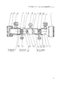
Более подробно изобретение поясняется с помощью чертежа, на котором изображен общий вид мембранного газоразделительного модуля (продольный разрез).The invention is explained in more detail using the drawing, which shows a General view of the membrane gas separation module (longitudinal section).
Мембранный модуль включает цилиндрический корпус 1, торцовые крышки 2, штуцеры 3 входа сырьевого газа, штуцеры 4 выхода пермеата, штуцер 5 выхода ретентата. Внутри корпуса расположены зеркально относительно центральной поперечной оси, по меньшей мере, два мембранных картриджа 6. Корпус содержит симметрично расположенные торцовые участки 7 большего диаметра, сопряженные коническими переходными участками 8 с центральным участком 9 меньшего диаметра. Длина торцовых участков с большим диаметром соответствует длине, ограниченной торцом корпуса и входной зоной 14 мембранных картриджей 6. Внутренний диаметр центрального участка корпуса 9 соответствует внешнему диаметру экранированной зоны мембранных картриджей 6 и выполнен с возможностью обеспечения их свободного монтажа/демонтажа до места уплотнения кольцевыми прокладками 16, после которого внутренний диаметр центральной части корпуса уменьшен до оптимального размера, обеспечивающего плотную посадку мембранных картриджей в корпусе.The membrane module includes a cylindrical housing 1,
Мембранные картриджи выполнены в виде пучков полых полимерных волокон 11, расположенных вокруг осевой перфорированной трубы 10 и своими концами загерметизированы в торцовых заливках 12 и 13. На торцовой поверхности заливки 12, расположенной возле торцовой крышки модуля, концы загерметизированных полых волокон открыты, а в торцовой заливке 13 на противоположном конце картриджа у центра модуля, концы полых волокон загерметизированы полностью. Мембранные картриджи имеют входную зону 14, расположенную в торцовых участках корпуса и экранированную зону 15, расположенную в центральном участке корпуса. Экранированная зона мембранного картриджа характеризуется наличием внешнего экрана, выполненного из непроницаемого материала, и закрыта фильтрационным полотном для улавливания механической пыли.Membrane cartridges are made in the form of bundles of
Корпус также содержит зоны входа сырьевого газа, сбора ретентата и пермеата. Зоны входа сырьевого газа образованы внутренней поверхностью корпуса в торцовых частях и каналами входа сырьевого газа из штуцеров 3. Зоны сбора пермеата образованы внутренней поверхностью корпуса в торцовых частях, торцовыми поверхностями заливок 12 картриджей с открытыми концами полых волокон и каналами выхода пермеата в штуцеры 4. Зона сбора ретентата образована внутренней полостью корпуса в центральной части, торцовыми поверхностями заливок 13 с закрытыми концами полых волокон и каналом выхода ретентата в штуцер 5.The housing also contains a zone of input of raw gas, the collection of retentate and permeate. The feed gas inlet zones are formed by the inner surface of the housing in the end parts and the raw gas inlet channels from the
Штуцеры 3 входа сырьевого газа расположены перпендикулярно продольной оси корпуса напротив входных зон 14 мембранных картриджей 6. Штуцеры 4 выхода пермеата расположены в торцовых участках корпуса перпендикулярно его продольной оси. Штуцер 5 выхода ретентата расположен в середине центрального участка корпуса перпендикулярно его продольной оси.The
Уплотнение мембранных картриджей 6 с корпусом 1 в центральном участке выполнено с помощью кольцевых прокладок 16, а в торцовых участках с помощью кольцевых прокладок 17. На торцовых заливках 12 и 13 мембранных картриджей 6 выполнены проточки для размещения в них кольцевых прокладок 16 и 17 с соответствующими технологическими размерами под участки внутреннего диаметра корпуса в местах его уплотнений.The sealing of the
В корпусе размещены упорные элементы 18, расположенные между торцовыми заливками 12 мембранных картриджей и торцовыми крышками 2. Упорные элементы могут быть выполнены, например, в виде цилиндрической втулки с соответствующим отверстием под канал выхода пермеата в штуцерах 4.
Устройство работает следующим образом.The device operates as follows.
Сырьевой газ поступает в мембранный модуль через каналы штуцеров 3, расположенные на торцовых участках 7 корпуса напротив входных зон 14 мембранных картриджей 6 в зоны входа сырьевого газа, и распределяется в кольцевом пространстве между внутренней поверхностью корпуса и наружной поверхностью входной зоны мембранных картриджей 6. Далее сырьевой газ проникает внутрь картриджей между мембранными волокнами 11 и движется вдоль мембранных волокон, что обеспечивается наличием внешнего экрана, к противоположным концам картриджей. По мере движения сырьевого газа из него через мембраны внутрь волокон проникает часть потока (пермеата). Не проникший через мембраны газ (ретентат) через отверстия в центральных трубах 10 выходит из центральных патрубков картриджей в зону сбора, расположенную в центре корпуса, и выходит из мембранного модуля через канал штуцера 5 выхода ретентата. Пермеат свободно выходит через внутренние открытые отверстия мембранных волокон 11 в зоны сбора и удаляется из мембранного модуля через соответствующие каналы штуцеров 4, расположенные в торцовых частях корпуса перпендикулярно его продольной оси.The feed gas enters the membrane module through the channels of the
Кольцевые прокладки 16 и 17 кроме уплотнения выполняют функцию разграничения зон нахождения газовых потоков. Наличие кольцевых прокладок 16 исключает недопустимый переток сырьевого газа в зону сбора ретентата, минуя половолоконные мембраны, а кольцевые прокладки 17 не позволяют сырьевому газу, минуя половолоконные мембраны, проникать в зону сбора пермеата.O-
При работе модуля в корпусе возникает большой перепад давления (до 10 МПа) между зонами входа сырьевого газа и зонами сбора пермеата, который может вызвать смещение мембранных картриджей 6 в сторону торцовых крышек 2, вследствие чего сырьевой газ будет поступать в каналы штуцеров 4, минуя половолоконные мембраны. Упорные элементы 18 предотвращают возможность смещения картриджей, позволяют выдерживать нагрузку от действия перепада давления и не препятствуют свободному прохождению потока пермета из зоны сбора в канал штуцера 4.When the module is operating in the housing, a large pressure drop (up to 10 MPa) occurs between the feed gas inlet zones and the permeate collection zones, which can cause the
Расположение штуцеров выхода пермеата на торцовых участках корпуса исключает проведение трудоемких операций монтажа/демонтажа трубопроводов, присоединяемых к торцовой крышке корпуса при ее монтаже/демонтаже.The location of the permeate outlet fittings on the end sections of the housing eliminates the time-consuming installation / disassembly of pipelines attached to the end cap of the housing during its assembly / disassembly.
Расположение штуцеров входа сырьевого газа согласно настоящему изобретению обеспечивает подачу исходного потока сразу непосредственно во входную зону каждого мембранного картриджа, что значительно сокращает объем зоны входа сырьевого газа и исключает необходимость наличия большого кольцевого канала (как у прототипа) между экранированной зоной картриджей и внутренней поверхностью корпуса. Это позволяет центральную часть корпуса, в которой расположена экранированная зона картриджей, выполнить с уменьшением диаметра до необходимых геометрических параметров, одновременно обеспечивающих свободный монтаж/демонтаж мембранных картриджей и их плотную посадку в месте уплотнения, что приводит к уменьшению массогабаритных параметров.The location of the raw gas inlet fittings according to the present invention provides a feed stream immediately directly to the inlet zone of each membrane cartridge, which significantly reduces the volume of the raw gas inlet zone and eliminates the need for a large annular channel (like the prototype) between the shielded zone of the cartridges and the inner surface of the housing. This allows the central part of the housing, in which the shielded zone of the cartridges is located, to be performed with a reduction in diameter to the necessary geometric parameters, while simultaneously providing free assembly / disassembly of the membrane cartridges and their tight fit in the seal, which leads to a decrease in weight and size parameters.
Уплотнения мембранных картриджей с корпусом, выполненные с применением кольцевых прокладок, имеют следующие преимущества. Кольцевые прокладки 16 значительно упрощают конструкцию мембранного модуля (по сравнению с прототипом), так как исключают применение более сложных по конструкции и сборке деталей, например втулки, что позволяет выполнить в мембранных картриджах выходной патрубок ретентата заподлицо с торцовой поверхностью картриджа. В результате сокращается зона сбора ретентата, что также приводит к уменьшению длины модуля.Seals of membrane cartridges with a housing made using ring gaskets have the following advantages. The
Также к положительным факторам следует отнести то, что выполнение мембранного газоразделительного модуля с расположением конструктивных элементов согласно настоящему изобретению позволяет рационально организовать распределение потоков газа, способствующее максимальному использованию рабочей поверхности мембранных картриджей, это повышает эффективность работы устройства.Also positive factors include the fact that the implementation of the membrane gas separation module with the arrangement of structural elements according to the present invention allows to rationally organize the distribution of gas flows, contributing to the maximum use of the working surface of the membrane cartridges, this increases the efficiency of the device.
Все признаки настоящего изобретения могут быть реализованы в конкретные конструктивные элементы (детали, сборочные единицы) мембранного газоразделительного модуля с использованием традиционных технологий изготовления трубопроводов и аппаратов.All the features of the present invention can be implemented in specific structural elements (parts, assembly units) of the membrane gas separation module using traditional technologies for the manufacture of pipelines and apparatuses.
Предлагаемый мембранный модуль прост по конструкции, технологичен в изготовлении, позволяет без существенных дополнительных затрат обеспечить эффективность извлечения гелия из природного газа.The proposed membrane module is simple in design, technologically advanced to manufacture, and without significant additional costs can ensure the efficiency of the extraction of helium from natural gas.
Данное техническое решение может быть реализовано в конструкциях модулей, работающих в составе блочного оборудования установок мембранного выделения гелиевого концентрата на нефтегазоконденсатных месторождениях.This technical solution can be implemented in the construction of modules operating as part of the block equipment of membrane separation units for helium concentrate in oil and gas condensate fields.
Однако необходимо добавить, что данное изобретение не ограничивается применением только для извлечения гелия из природного газа и может успешно использоваться в оборудовании и технологических процессах, где возникает необходимость разделить газовую смесь с любым другим компонентным составом.However, it must be added that this invention is not limited to use only for the extraction of helium from natural gas and can be successfully used in equipment and processes where it becomes necessary to separate the gas mixture with any other component composition.
В настоящее время на предлагаемое техническое решение мембранного модуля разработана проектная документация, проведены расчеты основных геометрических и технологических параметров.Currently, the design documentation for the proposed technical solution of the membrane module has been developed, and the basic geometric and technological parameters have been calculated.
Таким образом, изобретение решает поставленную задачу усовершенствования конструкции единичного мембранного газоразделительного модуля и обеспечивает указанный технический результат, что в итоге позволяет значительно сократить металлоемкость, снизить материальные затраты на изготовление устройства и эксплуатационные расходы.Thus, the invention solves the task of improving the design of a single membrane gas separation module and provides the specified technical result, which ultimately can significantly reduce the metal consumption, reduce material costs for the manufacture of the device and operating costs.
Claims (1)
Priority Applications (6)
| Application Number | Priority Date | Filing Date | Title |
|---|---|---|---|
| RU2015121552/05A RU2595699C1 (en) | 2015-06-05 | 2015-06-05 | Membrane gas-separating module |
| PCT/RU2015/000863 WO2016195535A1 (en) | 2015-06-05 | 2015-12-09 | Membrane gas separation module |
| CA2962256A CA2962256C (en) | 2015-06-05 | 2015-12-09 | Hollow fiber gas separation module having body with conical transition sections |
| CN201580074117.7A CN107206310B (en) | 2015-06-05 | 2015-12-09 | Gas membrane separation module |
| US15/526,278 US9987596B2 (en) | 2015-06-05 | 2015-12-09 | Membrane gas separation module |
| JP2017545849A JP6467518B2 (en) | 2015-06-05 | 2015-12-09 | Membrane gas separation module |
Applications Claiming Priority (1)
| Application Number | Priority Date | Filing Date | Title |
|---|---|---|---|
| RU2015121552/05A RU2595699C1 (en) | 2015-06-05 | 2015-06-05 | Membrane gas-separating module |
Publications (1)
| Publication Number | Publication Date |
|---|---|
| RU2595699C1 true RU2595699C1 (en) | 2016-08-27 |
Family
ID=55586372
Family Applications (1)
| Application Number | Title | Priority Date | Filing Date |
|---|---|---|---|
| RU2015121552/05A RU2595699C1 (en) | 2015-06-05 | 2015-06-05 | Membrane gas-separating module |
Country Status (6)
| Country | Link |
|---|---|
| US (1) | US9987596B2 (en) |
| JP (1) | JP6467518B2 (en) |
| CN (1) | CN107206310B (en) |
| CA (1) | CA2962256C (en) |
| RU (1) | RU2595699C1 (en) |
| WO (1) | WO2016195535A1 (en) |
Cited By (2)
| Publication number | Priority date | Publication date | Assignee | Title |
|---|---|---|---|---|
| RU181318U1 (en) * | 2017-03-13 | 2018-07-10 | Общество с ограниченной ответственностью "ТЕКОН МЕМБРАННЫЕ ТЕХНОЛОГИИ" | Membrane gas separation module |
| RU181320U1 (en) * | 2018-02-14 | 2018-07-10 | Общество с ограниченной ответственностью "ВЭЛТЕКС" | Membrane gas separation module |
Families Citing this family (3)
| Publication number | Priority date | Publication date | Assignee | Title |
|---|---|---|---|---|
| RU2562873C1 (en) * | 2014-06-27 | 2015-09-10 | Публичное акционерное общество "Газпром" | Drying pipeline inside |
| CN109069970B (en) * | 2016-04-07 | 2021-08-10 | 恩特格里斯公司 | Gas filter to be mounted on a gas panel for semiconductor manufacturing operations |
| RU171611U1 (en) * | 2017-02-15 | 2017-06-07 | Акционерное Общество "Грасис" | Gas separation membrane module |
Citations (6)
| Publication number | Priority date | Publication date | Assignee | Title |
|---|---|---|---|---|
| JP2010227837A (en) * | 2009-03-27 | 2010-10-14 | Toray Ind Inc | Hollow fiber membrane module |
| RU115239U1 (en) * | 2011-12-15 | 2012-04-27 | Закрытое Акционерное Общество "Грасис" | MEMBRANE GAS SEPARATING MODULE |
| RU120372U1 (en) * | 2011-12-15 | 2012-09-20 | Закрытое Акционерное Общество "Грасис" | MEMBRANE GAS SEPARATION UNIT |
| RU139442U1 (en) * | 2013-12-04 | 2014-04-20 | Закрытое Акционерное Общество "Грасис" | MEMBRANE GAS SEPARATING MODULE |
| RU143423U1 (en) * | 2014-02-14 | 2014-07-20 | Закрытое Акционерное Общество "Грасис" | MEMBRANE GAS SEPARATING MODULE |
| RU149982U1 (en) * | 2014-07-18 | 2015-01-27 | Закрытое Акционерное Общество "Грасис" | DEVICE FOR CLEANING THE GAS MIXTURE |
Family Cites Families (30)
| Publication number | Priority date | Publication date | Assignee | Title |
|---|---|---|---|---|
| US3503515A (en) * | 1968-10-03 | 1970-03-31 | Du Pont | Permeation separatory apparatus |
| AU516562B2 (en) * | 1977-04-08 | 1981-06-11 | Dow Chemical Company, The | Hollow fibre separatory device |
| US4961760A (en) * | 1989-02-09 | 1990-10-09 | The Dow Chemical Company | Hollow fiber membrane fluid separation device adapted for boreside feed |
| US5013437A (en) * | 1989-10-30 | 1991-05-07 | The Dow Chemical Company | Hollow fiber membrane fluid separation device adapted for boreside feed which contains multiple concentric stages |
| US5411662A (en) * | 1994-02-25 | 1995-05-02 | Praxair Technology, Inc. | Fluid separation assembly having an purge control valve |
| US5470469A (en) * | 1994-09-16 | 1995-11-28 | E. I. Du Pont De Nemours And Company | Hollow fiber cartridge |
| ATE373079T1 (en) * | 1999-06-21 | 2007-09-15 | Gen Hospital Corp | CELL CULTURE SYSTEMS AND METHODS FOR ORGAN SUPPORT FACILITIES |
| AU6949801A (en) * | 2000-07-10 | 2002-01-21 | Asahi Chemical Ind | Hollow thread film cartridge, hollow thread film module using the cartridge, andtank type filter |
| KR100354613B1 (en) * | 2001-11-06 | 2002-10-11 | 박헌휘 | Repairable immersed hollow fiber membrane module |
| WO2003086592A1 (en) * | 2002-04-03 | 2003-10-23 | Toyo Boseki Kabushiki Kaisha | Hollow fiber membrane module |
| JP4346340B2 (en) * | 2003-04-22 | 2009-10-21 | 株式会社クボタ | Operation method of coagulation filtration processing device |
| US20050121391A1 (en) * | 2003-09-26 | 2005-06-09 | Koch David H. | Reinforced filtration cartridge and method of making same |
| US7273549B2 (en) * | 2004-01-23 | 2007-09-25 | Geoscience Support Services Inc. | Membrane contactor apparatus including a module having hollow fiber membranes |
| US7338601B2 (en) * | 2004-12-10 | 2008-03-04 | Uop Llc | Membrane separation assemblies |
| US7534349B2 (en) * | 2005-09-02 | 2009-05-19 | Nephros, Inc. | Dual stage ultrafilter devices in the form of portable filter devices, shower devices, and hydration packs |
| US7943371B1 (en) * | 2006-10-12 | 2011-05-17 | Cleveland Medical Devices Inc. | System and testing biological and chemical agents using two or more cartridges simulating systems in the body and methods |
| WO2008081877A1 (en) * | 2006-12-29 | 2008-07-10 | Ube Industries, Ltd. | Shell feed type gas separation membrane module |
| JP5484659B2 (en) * | 2007-06-27 | 2014-05-07 | 三菱レイヨン株式会社 | Water purification cartridge and water purifier |
| US8790517B2 (en) * | 2007-08-01 | 2014-07-29 | Rockwater Resource, LLC | Mobile station and methods for diagnosing and modeling site specific full-scale effluent treatment facility requirements |
| US8876945B2 (en) * | 2009-08-17 | 2014-11-04 | Celgard, Llc | High pressure liquid degassing membrane contactors and methods of manufacturing and use |
| US9446354B2 (en) * | 2010-08-25 | 2016-09-20 | Repligen Corporation | Device, system and process for modification or concentration of cell-depleted fluid |
| US9718023B2 (en) * | 2010-11-04 | 2017-08-01 | Ube Industries, Ltd. | Gas separation membrane module and gas separation method |
| US9084962B2 (en) * | 2011-06-08 | 2015-07-21 | The Boeing Company | Fluid separation assembly and method |
| EP2755746B1 (en) * | 2011-09-12 | 2021-04-07 | 3M Innovative Properties Company | Improved contactors, cartridges, components, systems, and related methods |
| JP5966757B2 (en) * | 2012-08-17 | 2016-08-10 | 宇部興産株式会社 | Gas separation membrane module and hollow fiber element replacement method |
| US9623164B2 (en) * | 2013-02-01 | 2017-04-18 | Medtronic, Inc. | Systems and methods for multifunctional volumetric fluid control |
| JP2016524533A (en) * | 2013-06-12 | 2016-08-18 | エボニック ファイバース ゲゼルシャフト ミット ベシュレンクテル ハフツングEvonik Fibres GmbH | Membrane cartridge system |
| EP3181519A1 (en) * | 2013-06-21 | 2017-06-21 | Mitsubishi Rayon Co., Ltd. | Water purification cartridge and water purifier |
| US9339768B2 (en) * | 2013-08-23 | 2016-05-17 | 3M Innovative Properties Company | Multi-cartridge membrane contactors, modules, systems, and related methods |
| US10099181B2 (en) * | 2015-08-17 | 2018-10-16 | Asahi Kasei Kabushiki Kaisha | Hollow fiber membrane module |
-
2015
- 2015-06-05 RU RU2015121552/05A patent/RU2595699C1/en active
- 2015-12-09 WO PCT/RU2015/000863 patent/WO2016195535A1/en active Application Filing
- 2015-12-09 JP JP2017545849A patent/JP6467518B2/en active Active
- 2015-12-09 CA CA2962256A patent/CA2962256C/en active Active
- 2015-12-09 CN CN201580074117.7A patent/CN107206310B/en active Active
- 2015-12-09 US US15/526,278 patent/US9987596B2/en active Active
Patent Citations (6)
| Publication number | Priority date | Publication date | Assignee | Title |
|---|---|---|---|---|
| JP2010227837A (en) * | 2009-03-27 | 2010-10-14 | Toray Ind Inc | Hollow fiber membrane module |
| RU115239U1 (en) * | 2011-12-15 | 2012-04-27 | Закрытое Акционерное Общество "Грасис" | MEMBRANE GAS SEPARATING MODULE |
| RU120372U1 (en) * | 2011-12-15 | 2012-09-20 | Закрытое Акционерное Общество "Грасис" | MEMBRANE GAS SEPARATION UNIT |
| RU139442U1 (en) * | 2013-12-04 | 2014-04-20 | Закрытое Акционерное Общество "Грасис" | MEMBRANE GAS SEPARATING MODULE |
| RU143423U1 (en) * | 2014-02-14 | 2014-07-20 | Закрытое Акционерное Общество "Грасис" | MEMBRANE GAS SEPARATING MODULE |
| RU149982U1 (en) * | 2014-07-18 | 2015-01-27 | Закрытое Акционерное Общество "Грасис" | DEVICE FOR CLEANING THE GAS MIXTURE |
Cited By (2)
| Publication number | Priority date | Publication date | Assignee | Title |
|---|---|---|---|---|
| RU181318U1 (en) * | 2017-03-13 | 2018-07-10 | Общество с ограниченной ответственностью "ТЕКОН МЕМБРАННЫЕ ТЕХНОЛОГИИ" | Membrane gas separation module |
| RU181320U1 (en) * | 2018-02-14 | 2018-07-10 | Общество с ограниченной ответственностью "ВЭЛТЕКС" | Membrane gas separation module |
Also Published As
| Publication number | Publication date |
|---|---|
| CN107206310A (en) | 2017-09-26 |
| US9987596B2 (en) | 2018-06-05 |
| US20170341029A1 (en) | 2017-11-30 |
| WO2016195535A1 (en) | 2016-12-08 |
| JP6467518B2 (en) | 2019-02-13 |
| CA2962256C (en) | 2020-03-10 |
| CN107206310B (en) | 2020-06-12 |
| CA2962256A1 (en) | 2016-12-08 |
| JP2017535427A (en) | 2017-11-30 |
Similar Documents
| Publication | Publication Date | Title |
|---|---|---|
| RU2595699C1 (en) | Membrane gas-separating module | |
| US7510594B2 (en) | Gas separation membrane module assembly | |
| US7404843B2 (en) | Gas separation membrane module assembly | |
| EP1603680B1 (en) | Method for separating gas mixtures | |
| US7918921B2 (en) | Gas separation membrane module assembly with residue manifold | |
| RU2707515C2 (en) | New cartridges and modules for separation of fluids | |
| US4670145A (en) | Multiple bundle fluid separation apparatus | |
| CN103237834B (en) | Solid/fluid discrete device with include that solid/fluid separates for the method processing biomass | |
| US4746430A (en) | Fluid separation module | |
| US20080011157A1 (en) | Four-port gas separation membrane module assembly | |
| EP3049177B1 (en) | Self supporting monobloc structure for membrane filtration cartridges | |
| US20050172810A1 (en) | Filter element and mounting method | |
| RU2691335C1 (en) | Gas-separation membrane module for operation with chemically active gas | |
| CN104597209B (en) | Monoblock type gas sample gas processing means in situ | |
| TW201306922A (en) | Device for filtering and separating flowing media | |
| EP3883672A1 (en) | Device for separating components of a gas mixture | |
| CN212769998U (en) | Membrane module structure | |
| KR101160342B1 (en) | Hollow fibers membrane module | |
| CN109057769A (en) | A kind of novel gas well mouth tubular circulation eddy flow dehydration device | |
| US20220395781A1 (en) | Membrane module | |
| CN208599327U (en) | A kind of gas well mouth tubular type series connection outer circulation eddy flow dehydration device | |
| RU2691342C1 (en) | Gas-separation membrane module for operation with chemically active gas | |
| CN105903354B (en) | Film core pre-pressing structure | |
| CN104324579B (en) | Single gun oil-gas recovery separator | |
| CN214634476U (en) | Dirt remover |