JP5484659B2 - Water purification cartridge and water purifier - Google Patents
Water purification cartridge and water purifier Download PDFInfo
- Publication number
- JP5484659B2 JP5484659B2 JP2007169052A JP2007169052A JP5484659B2 JP 5484659 B2 JP5484659 B2 JP 5484659B2 JP 2007169052 A JP2007169052 A JP 2007169052A JP 2007169052 A JP2007169052 A JP 2007169052A JP 5484659 B2 JP5484659 B2 JP 5484659B2
- Authority
- JP
- Japan
- Prior art keywords
- activated carbon
- water
- cylindrical body
- main body
- cartridge
- Prior art date
- Legal status (The legal status is an assumption and is not a legal conclusion. Google has not performed a legal analysis and makes no representation as to the accuracy of the status listed.)
- Expired - Fee Related
Links
Images
Landscapes
- Separation Using Semi-Permeable Membranes (AREA)
- Water Treatment By Sorption (AREA)
Description
この発明は、浄水カートリッジおよび浄水器に関するものであり、特に家庭用の水道水栓に取り付けるタイプの浄水器およびこの浄水器に用いられる浄水カートリッジの小型化に係るものである。 The present invention relates to a water purification cartridge and a water purifier, and more particularly, to a water purifier that is attached to a tap water faucet for home use and a water purification cartridge that is used in the water purifier.
従来から、水道水栓に直接取り付けるいわゆる蛇口直結タイプの浄水器が知られている。この種の浄水器は、一般に、濾材を収容した浄水カートリッジと、吐出する水の種類すなわち原水・浄水を切換える切換機構を備えた本体とで構成されている。
また、この種の浄水器では、吸着性能に優れる活性炭繊維を濾材として採用したものがある。近年、この活性炭繊維の機械的強度を高めて取り扱い性を向上すべく、例えば、活性炭繊維を円筒状に成形して、この円筒状の外側から内側に向かって水を流過させることで塩素などを吸着する成形活性炭が提案されている(例えば、特許文献1参照)。
Moreover, in this kind of water purifier, there exist some which employ | adopted the activated carbon fiber which is excellent in adsorption | suction performance as a filter medium. In recent years, in order to increase the mechanical strength of this activated carbon fiber and improve the handleability, for example, the activated carbon fiber is formed into a cylindrical shape, and water is allowed to flow from the outside to the inside of the cylinder to make chlorine, etc. There has been proposed a molded activated carbon that adsorbs (see, for example, Patent Document 1).
ところで、蛇口直結タイプの浄水器においては、浄水器の下方の視界を遮ったり、水道水栓の操作の妨げにならないように更なる小型化が要望されている。しかしながら、上述した従来の浄水器では、円筒状に成形された活性炭が熱溶着樹脂などのバインダーによって固定されているため、同一体積の場合、バインダーが含まれている分だけ吸着能力が低下してしまう。その結果、成形活性炭が大型化して、浄水カートリッジの小型化が困難になってしまう。
一方、成形活性炭の吸着能力を向上するために、バインダーの割合を低下させた場合、成形活性炭の強度が低下するので、例えば、出荷時の運搬等によって衝撃が加わると、成形活性炭の形状が崩れて部分的に吸着性能が低下してしまう虞がある。
By the way, in the faucet direct connection type water purifier, further downsizing is required so as not to obstruct the view below the water purifier or to disturb the operation of the water tap. However, in the above-described conventional water purifier, the activated carbon formed in a cylindrical shape is fixed by a binder such as a heat-welding resin, so in the case of the same volume, the adsorption capacity is reduced by the amount that the binder is included. End up. As a result, the molded activated carbon becomes large, and it becomes difficult to reduce the size of the water purification cartridge.
On the other hand, when reducing the binder ratio to improve the adsorption capacity of the molded activated carbon, the strength of the molded activated carbon will decrease, so for example, if impact is applied by transportation at the time of shipment, the shape of the molded activated carbon collapses Therefore, there is a possibility that the adsorption performance is partially reduced.
そこで、この発明は、成型活性炭の形状が崩れるのを防止するとともに、濾材の吸着性能を損なうことなく浄水カートリッジの小型化を図ることができる浄水カートリッジおよび浄水器を提供するものである。 Therefore, the present invention provides a water purification cartridge and a water purifier that can prevent the shape of the molded activated carbon from collapsing and can reduce the size of the water purification cartridge without impairing the adsorption performance of the filter medium.
上記課題を解決するために、請求項1に記載した浄水カートリッジは、ケース(例えば、実施の形態におけるケース13)内部に両端が開口した筒状体(例えば、実施の形態における筒状体44)を備え、該筒状体の内部に繊維状活性炭をバインダーを用いて一定形状に成形した成形活性炭(例えば、実施の形態における活性炭56)と、濾過膜(例えば、実施の形態における中空糸膜57)と、整流板(例えば、実施の形態における整流板54)とを収容し、前記ケース内に取り入れた原水を、前記筒状体の入口(例えば、実施の形態における入口47)から出口(例えば、実施の形態における出口48)へ通水することにより浄化する浄水カートリッジであって、前記筒状体は、その内壁面の少なくとも一部分に、その入口側から出口側に向けて先細り状となるテーパー(例えば、実施の形態における縮径部53a)を備え、前記筒状体の断面形状が略円形に形成されるとともに、前記成形活性炭が略円柱状または略円錐台状に形成され、前記成形活性炭の側面は、前記テーパー部分で前記筒状体の内壁面に面で接しており、繊維状活性炭の含有量は、85〜99%の範囲であり、その充填後密度が0.15〜0.30g/mlの範囲であり、前記濾過膜は、前記筒状体の内部に固定され、前記整流板は、前記濾過膜と前記成形活性炭との間に配置されていることを特徴とする。
In order to solve the above problem, the water purification cartridge according to
請求項2に記載した浄水カートリッジは、前記成形活性炭が、前記筒状体の入口側からの圧入によって、前記筒状体に固定されていることを特徴とする。 The water purification cartridge described in claim 2 is characterized in that the molded activated carbon is fixed to the cylindrical body by press-fitting from the inlet side of the cylindrical body.
請求項3に記載した浄水カートリッジは、前記成形活性炭を基準として、前記筒状体の入口側に不織布を設けたことを特徴とする。
The water purification cartridge described in
請求項4に記載した浄水カートリッジは、前記整流板には、その中心から、外周部に向けて伸びる複数本のアーム(例えば、実施の形態におけるアーム部54d)が設けられていること特徴とする。
The water purification cartridge described in
請求項5に記載した浄水器は、請求項1から4のいずれか一項に記載の浄水カートリッジ(例えば、実施の形態における浄水カートリッジ4)と、浄水吐出口を有する浄水器本体(例えば、実施の形態における本体3)とからなることを特徴とする。
A water purifier according to
請求項6に記載した浄水器は、前記ケースの外壁および浄水器本体それぞれに対し、いずれか一方に雄コネクタ部(例えば、実施の形態における雄コネクタ14a,14b,14c)を設け、他方にこれに差し込み嵌合される雌コネクタ部(例えば、実施の形態における雌コネクタ12a,12b,12c)を設け、前記雄コネクタ部と前記雌コネクタ部との嵌合により、前記浄水器本体と前記カートリッジとの間の水通路(例えば、実施の形態における浄水通路26、原水導入通路27)が形成されるとともに前記カートリッジが前記浄水器本体に支持されることを特徴とする。
The water purifier according to
請求項1に記載した発明によれば、筒状体の内面にテーパーを設けることで、成形活性炭が、原水の流入によって出口側に変位するのを防止しつつ、成形活性炭の側面をケースによって保持することができるため、衝撃などにより成形活性炭の形状が崩れるのを防止することができる効果がある。
また、成形活性炭の形状が崩れるのを防止することができるため、例えば、従来の成形活性炭に含まれるバインダーの割合よりも、成形活性炭に含まれるバインダーの割合を低下させることができ、したがって、吸着性能を維持したまま小型化を図ることができる。
さらに、成形活性炭がテーパー部分で筒状体の内壁面に面で接しているので、成形活性炭と筒状体の内壁面との間に隙間が生じるのを抑制して原水を成形活性炭内に流過させることができるため、成形活性炭の吸着性能を十分に発揮させることができる。
加えて、成形活性炭における繊維状活性炭の含有量を85〜99%の範囲とし充填後密度を0.15〜0.30g/mlとすることで、繊維状活性炭の含有量が85%未満、充填後密度が0.15g/ml未満および0.30g/mlよりも大きい場合と比較して必要とする吸着性能を十分に確保しつつ小型化することができる。
According to the first aspect of the present invention, by providing a taper on the inner surface of the cylindrical body, the side of the molded activated carbon is held by the case while preventing the molded activated carbon from being displaced to the outlet side due to the inflow of raw water. Therefore, there is an effect that the shape of the formed activated carbon can be prevented from collapsing due to impact or the like.
In addition, since the shape of the molded activated carbon can be prevented from collapsing, for example, the ratio of the binder contained in the molded activated carbon can be made lower than the ratio of the binder contained in the conventional molded activated carbon. Miniaturization can be achieved while maintaining the performance.
Furthermore, since the molded activated carbon is in contact with the inner wall surface of the cylindrical body at the tapered portion, the formation of a gap between the molded activated carbon and the inner wall surface of the cylindrical body is suppressed, and raw water is allowed to flow into the molded activated carbon. Therefore, the adsorption performance of the molded activated carbon can be sufficiently exhibited.
In addition, the content of the fibrous activated carbon in the formed activated carbon is in the range of 85 to 99% and the density after filling is 0.15 to 0.30 g / ml. As compared with the case where the after density is less than 0.15 g / ml and larger than 0.30 g / ml, it is possible to reduce the size while sufficiently securing the necessary adsorption performance.
さらに、成形活性炭の側面と筒状体の内周面とを略円形にすることができるため、小型化の要件を満たしつつ、両者の接触面積を増加することができ、したがって、成形活性炭の形状が崩れるのを防止することができる効果がある。 Furthermore, since the side surface of the molded activated carbon and the inner peripheral surface of the cylindrical body can be made substantially circular, the contact area between the two can be increased while satisfying the requirements for miniaturization. There is an effect that can prevent the collapse.
請求項2に記載した発明によれば、成形活性炭が筒状体に圧入されることで、成形活性炭の側面と筒状体の内壁面との間に隙間が生じるのを抑制し、より確実に原水が成形活性炭内を流過するように設定することができるため、さらに成形活性炭の吸着性能を十分に発揮させることができる。 According to the invention described in claim 2 , the molded activated carbon is press-fitted into the cylindrical body, thereby suppressing the generation of a gap between the side surface of the molded activated carbon and the inner wall surface of the cylindrical body, and more reliably. Since the raw water can be set so as to flow through the formed activated carbon, the adsorption performance of the formed activated carbon can be sufficiently exhibited.
請求項3に記載した発明によれば、不織布がプレフィルタとして機能するため、ケース内部に比較的大きな被ろ過物が流入するのを防止することができる。また、不織布によって成形活性炭から出る粉がろ過ユニットのケースの外に流出するのを防止することができる。
According to the invention described in
請求項4に記載した発明によれば、アームが複数設けられていることで、筒状体の内部を入口側から出口側へ向かう水流がアームに衝突するため、当該水流が局所的に偏ることなく水を筒状体内に均等に行き渡らせることができ、したがって、成形活性炭と濾過膜の利用効率を向上させることができる効果がある。
According to the invention described in
請求項5に記載した発明によれば、活性炭の吸着性能を低下させることなしに浄水カートリッジを小型化することができるため、浄水器自体の小型化を図ることができ、したがって、商品性を向上させることができる効果がある。
According to the invention described in
請求項6に記載した発明によれば、浄水器本体とカートリッジとを結合するために設けられた雄コネクタ部と雌コネクタ部とが、それぞれ水通路を構成していることで、従来の浄水器のように結合手段と通路とを個別に設けている場合よりも、結合手段を配置するスペースを省略できる分だけ浄水器の本体とカートリッジとを接近配置させることができ、したがって、浄水器の寸法を短縮して浄水器の小型化を図ることができる効果がある。 According to the sixth aspect of the present invention, the male connector portion and the female connector portion provided for coupling the water purifier main body and the cartridge each constitute a water passage, whereby a conventional water purifier is provided. Thus, the water purifier body and the cartridge can be arranged closer to each other than the case where the coupling means and the passage are separately provided as in the case of the above, so that the space for arranging the coupling means can be omitted. There is an effect that the water purifier can be reduced in size by reducing the length of the water purifier.
以下、図面を参照しながらこの発明の実施の形態を説明する。
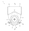
図1,2において、符号1は浄水器を示している。この浄水器1は水道水栓2のアーム2aに取り付けられる本体3と、この本体3の後面に着脱自在に設けられた略円柱状の浄水カートリッジ4とで構成されている。なお、この実施の形態では、水道水栓2のアーム2aに対して図1に示すように浄水器1が取り付けられている状態で、水道水栓2の正面つまりアーム2aの延長線上に立った使用者から見た前後方向を浄水器の前後方向と称し、上記状態で使用者から見た左右方向を浄水器の左右方向と称する。
Embodiments of the present invention will be described below with reference to the drawings.
1 and 2,
本体3は、上部に原水受入口5を備え、この原水受入口5の周縁に設けられたリング状の取付け治具6を介して水道水栓2のアーム2aに接続されている。本体3の下部には、原水を吐出するシャワー出口7(図5参照)と浄水を吐出する浄水出口8(図4参照)とが配置されている。
The
本体3の前面には、本体3の左右幅方向に長尺な操作レバー9が取り付けられている。操作レバー9は、浄水器1から吐出する水の種類すなわち原水または浄水を選択するものであり、左右幅方向の中心部分が本体3に軸支されている。この操作レバー9の左端部9aと右端部9bとがそれぞれ前後方向に揺動可能になっている。
An
操作レバー9の中央部9cは、原水受入口5の周縁の形状に沿って後方に向かって湾曲した形状になっている。一方、中央部9cの左右に設けられた左・右端部9a,9bは、中央部9cよりも幅広に形成され、浄水器1の左右方向に沿って延びている。右端部9bには、前面にシャワーマーク10が形成され、左端部9aには、前面に浄水マーク11が形成されている。このように、操作レバー9の中央部9cが後方に向かってやや湾曲して形成されていることで、操作レバー9の前方への張り出しと幅方向の寸法とが大きくなるのを抑制している。
The
図3に示すように、本体3の背面には、後方に向かって開口する略筒状の雌コネクタ12a,12b,12cが形成されている。これら雌コネクタ12a,12b,12cは、本体の左右幅方向にほぼ沿って配列されている。より具体的には、本体3の左側(図3中右側)に雌コネクタ12aが配置され、本体3の左右中央には雌コネクタ12bが配置され、さらに、本体3の右側(図3中左側)には、雌コネクタ12cが配置されている。雌コネクタ12bを基準として雌コネクタ12aと雌コネクタ12cとがそれぞれ左右対称位置に配置され、雌コネクタ12bは、雌コネクタ12a,12cよりも若干上方に配置されている。
As shown in FIG. 3, substantially cylindrical
一方、カートリッジ4は、略円筒状のケース13を備えている。このケース13の外周壁には、上述した雌コネクタ12a,12b,12cに対応した位置に、略円筒状の雄コネクタ14a,14b,14cが形成されている。雄コネクタ14bは、略円筒状に形成されたカートリッジ4の軸方向の中央位置に配置されており、この雄コネクタ14bを基準に、雄コネクタ14aと雄コネクタ14cとがそれぞれ左右対称位置に配置されている。
On the other hand, the
ここで、雄コネクタ14aは上述した雌コネクタ12aと対をなすものであり、雄コネクタ14bは雌コネクタ12bと対をなすものである。また、雄コネクタ14cは雌コネクタ12cと対をなすものである。上述した雌コネクタ12aと雄コネクタ14aとでカートリッジ4と本体3との間の浄水用の通路である浄水通路26を構成し、雌コネクタ12bと雄コネクタ14bとでカートリッジ4と本体3との間の原水用の通路である原水導入通路27を構成している。
Here, the
雄コネクタ14aの周囲にはOリング15が2重に装着され、雄コネクタ14bの周囲にはOリング15が一つだけ装着されている。雄コネクタ14cの周囲にはOリング15が装着されていない。なお、雄コネクタ14aの周囲には、Oリング15を一つだけ設けるようにしてもよく、雄コネクタ14cの周囲にOリング15を設けるようにしてもよい。
A double O-
このように構成することで、雄コネクタ14aを雌コネクタ12aに挿入し、雄コネクタ14bを雌コネクタ12bに挿入し、さらに、雄コネクタ14cを雌コネクタ12cに挿入して押し込むと、雌コネクタ12a,12b,12cにそれぞれ雄コネクタ14a,14b,14cが嵌合し、Oリング15が装着されている雄コネクタ14a,14bについては、Oリング15によってシールがなされ、雄コネクタ14a,14bが挿抜方向へ変位するのが規制され、これら雄コネクタ14a,14b,14cおよび雌コネクタ12a,12b,12cを介してカートリッジ4が本体3に支持されることとなる。
With this configuration, when the
カートリッジ4の、雄コネクタ14aと雄コネクタ14bとの間、および、雄コネクタ14bと雄コネクタ14cとの間には、それぞれ本体3側に向かって突出する係止片16が形成されている。これら係止片16には、それぞれネジ孔17が形成されている。一方、本体3の雌コネクタ12aと雌コネクタ12bとの間、および雌コネクタ12bと雌コネクタ12cとの間には、本体3の底壁18の上記係止片16のネジ孔17に対応する位置に、遊挿孔19が形成されている。
Locking
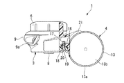
図4に示すように、本体3にカートリッジ4を装着した状態で、遊挿孔19を介して下方からビス20を挿入して係止片16のネジ孔17に螺入することで、本体3の底壁18と係止片16が固定され、カートリッジ4の本体3から離脱する方向への移動が規制される。なお、ビス20で本体3の底壁18とカートリッジ4の係止片16とを固定する場合について説明したが、ビス20による固定ではなく、例えば、爪などを用いて係止片を底壁18に係合させるようにしてもよい。なお、上述した係止片16は、カートリッジ4が本体3から離脱する方向への変位を規制するだけのために設けられたものであって、カートリッジ4を支持するためのものではない。
As shown in FIG. 4, with the
図3,5に示すように、本体3に装着されたカートリッジ4は、その中心軸sが本体3の底壁18と略同一の高さに配置されている。また、上述した雄コネクタ14a,14b,14cは、本体3に装着された状態で、カートリッジ4の中心よりも上部で浄水器1の後方から前方に向かって伸びている。
As shown in FIGS. 3 and 5, the
一方、本体3の背面には、カートリッジ4の周面に対応した形状、すなわち本体3の前面側に向かって凹形となる側面視略弧状に形成された凹部38を備えている。これにより、カートリッジ4が本体3に装着されたときに、カートリッジ4の外周壁が凹部38に当接して、カートリッジ4の前部が本体3側に若干入り込むこととなる。
On the other hand, the back surface of the
また、本体3の背面上縁部分は、カートリッジ4の周面に沿って当接しつつ後方に伸びてつば部21を形成している。このつば部21は、本体3の左右幅方向の中心ほど後方に向かって延びる凸状に形成されている(図2参照)。このつば部21を設けていることで、本体3にカートリッジ4を装着する際に、カートリッジ4を正しい姿勢で本体3の凹部38に導くことができるとともに、装着されたカートリッジ4の両端部が上下方向に変位するのを規制することができる。なお、雌コネクタ12a,12b,12cの上縁部分22は有段成形され、この有段成形された上縁部分22だけが上述のつば部21と同様に、カートリッジ4の周面に当接するように上縁部分22の上方に向かうほど後方に向かって延びている(図3参照)。
In addition, the rear upper edge portion of the
ところで、図5に示すように、本体3の原水受入口5には、水道水栓2に接続された状態で、原水受入口5と水道水栓との間のシール材としてゴムパッキン24が設けられている。さらに、ゴムパッキン24の下方には中心部分に開口部(図示せず)が形成された樹脂製の仕切り板25が配置されている。この仕切り板25は、本体3の内壁に上下方向に沿って形成された複数のリブ(図示せず)上に載置されている。
By the way, as shown in FIG. 5, the raw
仕切り板25の下方には、上述した操作レバー9に連係した切換弁23が左右方向(図3の紙面上下方向)に揺動自在に収容されている。この切換弁23は、原水受入口5と前述した原水導入通路27との連通状態、および、原水受入口5と原水をシャワー出口7に導く原水通路28との連通状態を切換えるものである。
Below the
より具体的には、本体3内部には、操作レバー9側に切換弁ホルダー29が配置され、切換弁23は、この切換弁ホルダー29に回転軸30が回動自在に支持されている。この回転軸30は、前述した操作レバー9の回動軸に、軸線を共有した状態で固定されている。また、切換弁ホルダー29に収容されている回転軸30の周囲にはシール材としてOリング33が装着されている。
More specifically, a switching
切換弁23は、その回転軸30の上部から後方に向かって伸びるアーム31を備えており、このアーム31の端部には、下方に向かって開口する略有底円筒状の弁体ホルダー32が形成されている。この弁体ホルダー32は、弁体35を上下方向に摺動自在に支持するものであり、その内部にはコイルスプリング34が収容され、このコイルスプリング34によって弁体35が下方に付勢されている。
The switching
弁体35の下方には、原水導入通路27と原水通路28の開口部(図示せず)が配置されており、この開口部と弁体35との間にアーム31の揺動する方向に沿って長尺に形成されたゴム製の弁座パッキン36が設けられている。この弁座パッキン36には、原水導入通路27および原水通路28の開口部の形状に対応した孔(図示せず)が、本体3の左右幅方向に沿って並んで配置されている。
An opening (not shown) of the raw
つまり、ユーザによってシャワーマーク10が設けられた操作レバー9の右端部9bが後方に向かって押された場合、操作レバー9の回転軸が反時計周りに回動し、この回動に伴い切換弁23の回転軸30が回動してアーム31が左方向に揺動する。そして、弁体35によって原水導入通路27の開口部周縁の弁座パッキン36が上方から押圧され、原水導入通路27の開口部が閉塞される。これにより、原水通路28の開口部が開放状態となり、原水受入口5から受け入れた原水は、原水通路28を通じてシャワー出口7から下方に向かって放出されることとなる。
That is, when the
一方、ユーザによって浄水マーク11が設けられた操作レバー9の左端部9aが後方に向かって押された場合、操作レバー9の回転軸が時計周りに回動し、この回動に伴い切換弁23の回転軸30が回動してアーム31が右方向揺動する。そして、弁体35によって原水通路28の開口部周縁の弁座パッキン36が上方から押圧され、原水通路28の開口部が閉塞される。これにより、原水受入口5から受け入れた原水は、原水導入通路27すなわち雌コネクタ12b、雄コネクタ14bを介してカートリッジ4に導入され、その後、カートリッジ4でろ過された浄水が浄水通路26すなわち雄コネクタ14a、雌コネクタ12aを介して本体3に戻り、浄水出口8から下方に向かって放出される。
On the other hand, when the
次に、図6,7を参照しながらカートリッジ4について説明する。なお、カートリッジ4において、原水が流入する側を入口47、浄水が流出する側を出口48とする。
カートリッジ4のケース13は、上述した雄コネクタ14a,14b,14cを備えた略有底円筒状のケース本体13aと、ケース本体13aの開口部40の内側に嵌合して超音波溶着などによってケース本体13aに固定される蓋13bとで構成されている。ケース本体13aの内壁41には、雄コネクタ14aと雄コネクタ14cとの間の範囲にケース本体13aの底壁13cに向かって内径が徐々に縮径する縮径部42が形成されている。
Next, the
The
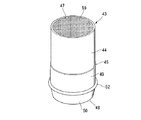
ケース本体13aの内部には、ろ過ユニット43が収容されている。ろ過ユニット43は、略円筒状の筒状体44を備え、この筒状体44の外周面には、前述した雄コネクタ14bが構成する原水導入通路27の延長線上に、段差部45が形成されている。このように雄コネクタ14bの原水導入通路27の延長線上に段差部45が配置されていることで、原水導入通路27を介してカートリッジ4のケース13内に流入した原水が段差部45に当たって、スムーズに入口47方向に向かうようになっている。
A
ろ過ユニット43には、段差部45よりも出口48側に、段差部45の入口47側よりも大径に形成された大径部49が形成されている。さらに、筒状体44の出口48近傍の外周面には、出口48側に向かって徐々に縮径する縮径部50が形成されている。大径部49の縮径部50近傍にはリング状の溝51が形成され、この溝51にOリング52が装着されている。
The
一方、蓋13bは、その内面に筒状体44の入口47側の端面を押圧する複数の突出部59が形成されており、この突出部59の高さ分だけ、蓋13bとろ過ユニット43の筒状体44との間に原水の流路としての隙間が形成されるようになっている。
On the other hand, the
ここで、ろ過ユニット43を入口47側からケース本体13aの内部にスライド挿入してケース本体13aの開口部40に蓋13bを装着すると、ろ過ユニット43の筒状体44がケース本体13a内に押し込まれ、縮径部42の雄コネクタ14a近傍の内周面にOリング52が突き当たって、ろ過ユニット43の入口47方向への変位が規制された状態となる。ケース本体13aの内部空間は、Oリング52によって仕切られ、Oリング52よりも入口47側に原水が入口47側に流過する通路T1が形成され、Oリング52よりも出口48側に浄水が浄水通路26に向かって流過するための通路T2が形成される。
Here, when the
ろ過ユニット43の筒状体44の内部には、吸着体である活性炭56とろ過膜である中空糸膜57とが、カートリッジ4の長手方向に沿って直列に配置されている。ここで、前述した雄コネクタ14bは、筒状体44に装着されたOリング52よりも活性炭56が収容されている側のケース本体13aの外周壁に配置され、雄コネクタ14aは、Oリング52よりも中空糸膜57が収容されている側のケース本体13aの外周壁に配置されている。
Inside the
ろ過ユニット43の内部構成をより具体的に説明する。ろ過ユニット43の筒状体44の内周面には、上述した筒状体44の外周面に形成された段差部45よりもやや入口47側に段差53が形成され、この段差53近傍の筒状体44の内部に、段差53の入口47側近傍の内径と略同一の外径を有し複数の孔54aを備えた整流板54が挿入されている。孔54aは、筒状体44の内部を入口47側から出口48側への処理中の水の流過を許容しつつ、活性炭56から中空糸膜57に向かう水の流れを整えて水流の偏りを防止する機能を有している。
The internal configuration of the
ここで、図8に示すように、整流板54は、筒状体44の段差53近傍の内径と略同一外径で環状に形成された外環部54bと、整流板54の中心に配置され略円盤状の邪魔板部54cと、この邪魔板部54cから放射状に配置されるとともに邪魔板部54cと外環部54bとを連結して前述した複数の孔54aを画成する複数本のアーム部54dとで構成されている。なお、図8では、その中心から等角度に4本のアーム部54dが設けられているが、整流板54は、複数の孔54aを備えていれば、アーム部54dの本数や形状は特に限られるものではなく、また、整流板54が筒状体44の内周部に一体に形成されていても良い。
Here, as shown in FIG. 8, the rectifying
図6に示すように、段差53よりも入口47側の筒状体44の内周面は、出口48側よりも拡径して形成されるとともに入口47から段差53に向かって徐々に縮径して先細り状となる縮径部53aが形成されている。ここで、段差53は整流板54のストッパーの機能を有しており、整流板54の出口48方向への変位を規制している。
As shown in FIG. 6, the inner peripheral surface of the
整流板54の入口47側には、吸着体である活性炭56が配置されている。この活性炭56は、活性炭繊維が熱溶着樹脂等のバインダーで固定された、いわゆる成形活性炭であって、筒状体44の入口47側の内径とほぼ同じ外径を備えた略円柱状に形成されている。このように構成された活性炭56は、入口47側から筒状体44内に圧入によって収容され、活性炭56の外周面が筒状体44の縮径部53aの内周面を押圧している。すなわち、活性炭56の側面が筒状体44の内周面と接する状態になる。なお、活性炭56は略円錐台状に形成してもよい。
An activated
一方、筒状体44内部の整流板54よりも出口48側には、ろ過膜である中空糸膜57が収容されている。中空糸膜57は、筒状体44の外周面に形成された縮径部50に対応する位置に、ウレタン樹脂、エポキシ樹脂、ポリオレフィン樹脂などのポッティング材58によって膜の原水側と浄水側とが遮断されている。また、筒状体44内の最も入口47側には、プレフィルタとして不織布55が成型活性炭の入口47側の面に当接して取り付けられている。
On the other hand, a
すなわち、水道水栓2から吐出する原水は、原水受入口5から浄水器1の内部に流入し、操作レバー9の操作状態に応じて切換弁23によって閉塞されていない原水導入通路27または原水通路28に流入する。原水通路28に原水が流入した場合は、そのままシャワー出口7に導かれてシャワー出口7から浄水器1の外へシャワー状の原水として流出される。
That is, the raw water discharged from the tap water faucet 2 flows into the
一方、原水導入通路27に原水が流入した場合、原水は、原水導入通路27を構成する雌コネクタ12bと雄コネクタ14bとを介してカートリッジ4のケース13内に流入する。そして、図6に示すように、ケース13の内周面とろ過ユニット43の外周面との間に形成される通路T1をろ過ユニット43の入口47側に向かって流過した後、原水が蓋13bの内面にぶつかりろ過ユニット43と蓋13bとの間に回り込み、ろ過ユニット43の入口47側から不織布55を通じて筒状体44内部に浸入する。
On the other hand, when raw water flows into the raw
筒状体44の内部に浸入した原水は、活性炭56による吸着および中空糸膜57によるろ過を経て、浄水としてろ過ユニット43の出口48側から通路T2に流出する。このろ過ユニット43から流出した浄水は、浄水通路26を構成する雄コネクタ14a、雌コネクタ12aを介して本体3に流入し、本体3の下方に臨む浄水出口から流下することとなる。
The raw water that has entered the inside of the
次に、図9を参照して上述した成形活性炭である活性炭56の実施例について説明する。
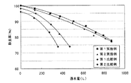
図9は、縦軸を除去率(%)、横軸を通水量(L)とした場合の成形活性炭の第1実施例、第2実施例、第1比較例および第2比較例のグラフを示したものである。第1実施例、第2実施例、第1比較例および第2比較例の各条件を以下の表に示す。なお、除去率とは、カートリッジ4の入口側の塩素量とカートリッジ4の出口側の塩素量を求めて、(入口側−出口側)/入口側×100(%)となる値である。また、通水量とは、カートリッジ4の使用開始から通水した水量の積算値である。
Next, an embodiment of the activated
FIG. 9 is a graph of the first example, the second example, the first comparative example, and the second comparative example of the molded activated carbon when the vertical axis is the removal rate (%) and the horizontal axis is the water flow rate (L). It is shown. The conditions of the first example, the second example, the first comparative example, and the second comparative example are shown in the following table. The removal rate is a value obtained by calculating the amount of chlorine on the inlet side of the
第1実施例は、繊維状活性炭:粒状活性炭:バインダーのそれぞれの配合比(%)を90:5:5、充填後の密度(以下、単に充填密度という)を0.22g/mlとした場合であり、通水開始から通常交換の目安となる除去率80%に低下するまでの通水量が800(L)となった。これは、一般家庭で使用する場合、2.5ヶ月程度の使用が可能となる通水量に相当する。 In the first example, the ratio (%) of fibrous activated carbon: granular activated carbon: binder is 90: 5: 5, and the density after filling (hereinafter simply referred to as filling density) is 0.22 g / ml. The water flow rate from the start of water flow until the removal rate decreased to 80%, which is a standard for normal replacement, was 800 (L). This corresponds to the amount of water that can be used for about 2.5 months when used in a general household.
次に、第2実施例は、繊維状活性炭:粒状活性炭:バインダーのそれぞれの配合比(%)を95:0:5、充填密度を0.20g/mlとした場合であり、通水開始から通常交換の目安となる除去率80%に低下するまでの通水量が800(L)となった。これも第1実施例と同様に、一般家庭で使用する場合、2.5ヶ月程度の使用が可能となる通水量に相当する。 Next, 2nd Example is a case where each compounding ratio (%) of fibrous activated carbon: granular activated carbon: binder is 95: 0: 5, and the packing density is 0.20 g / ml. The water flow rate until the removal rate decreased to 80%, which is a standard for normal replacement, was 800 (L). Similarly to the first embodiment, this corresponds to the amount of water that can be used for about 2.5 months when used in a general household.
そして、第1比較例は、繊維状活性炭:粒状活性炭:バインダーのそれぞれの配合比(%)を90:5:5、充填密度を0.12g/mlとした場合であり、通水開始から通常交換の目安となる除去率80%に低下するまでの通水量は400L程度となった。これは一般家庭で使用する場合、1ヶ月強程度の使用が可能となる通水量に相当する。 The first comparative example is a case where the blending ratio (%) of fibrous activated carbon: granular activated carbon: binder is 90: 5: 5, and the packing density is 0.12 g / ml. The amount of water passed until the removal rate was reduced to 80%, which was a guide for replacement, was about 400L. This corresponds to the amount of water that can be used for a little over a month when used in a general household.
さらに、第2比較例は、繊維状活性炭:粒状活性炭:バインダーのそれぞれの配合比(%)を50:45:5、充填密度を0.40g/mlとした場合であり、通水開始から通常交換の目安となる除去率80%に低下するまでの通水量は300L程度となった。これは一般家庭で使用する場合、1ヶ月程度の使用が可能となる通水量に相当する。 Furthermore, the second comparative example is a case where the blending ratio (%) of fibrous activated carbon: granular activated carbon: binder is 50: 45: 5, and the packing density is 0.40 g / ml. The amount of water flow until the removal rate was reduced to 80%, which is a guide for replacement, was about 300L. This corresponds to the amount of water that can be used for about one month when used in a general household.
また、上述した第1実施例の繊維状活性炭の配合比を90%以下とした場合、配合比85%までは除去率80%に低下するまでの通水量が800L程度となるが、繊維状活性炭の配合比が85%未満の場合、繊維状活性炭の配合比が少なくなるほど除去率80%に低下するまでの通水量の減少が顕著になることが判明した。また、繊維状活性炭の配合比が95%以上では、99%を超えると成型活性炭としての形状を保つのが困難になることが判明した。 Further, when the blending ratio of the fibrous activated carbon of the first embodiment described above is 90% or less, the water flow rate until the removal rate is reduced to 80% is about 800 L until the blending ratio is 85%. When the blending ratio is less than 85%, it has been found that the decrease in the amount of water flow until the removal rate decreases to 80% as the blending ratio of the fibrous activated carbon decreases. Further, it has been found that when the blending ratio of the fibrous activated carbon is 95% or more, if it exceeds 99%, it becomes difficult to maintain the shape as the molded activated carbon.
さらに、繊維状活性炭の配合比を85〜99%の間に設定して、充填密度を0.20g/ml以下に設定した場合、充填密度0.15g/mlまでは除去率80%に低下するまでの通水量が800L程度を維持できるが、0.15g/ml未満の場合、除去率80%に低下するまでの通水量の減少が顕著になることが判明した。また、充填密度が0.2g/ml以上の場合、0.3g/mlを超えると、著しく通水抵抗が上昇するために局所的な偏流が発生して、除去率80%に低下するまでの通水量の減少が顕著になることが判明した。 Furthermore, when the blending ratio of the fibrous activated carbon is set between 85 to 99% and the packing density is set to 0.20 g / ml or less, the removal rate is reduced to 80% until the packing density is 0.15 g / ml. It was found that the water flow rate until about 800L can be maintained, but when the water flow rate is less than 0.15 g / ml, the reduction of the water flow rate until the removal rate is reduced to 80% becomes remarkable. In addition, when the packing density is 0.2 g / ml or more, when the density exceeds 0.3 g / ml, the water flow resistance is remarkably increased, so that local drift occurs and the removal rate is reduced to 80%. It was found that the reduction of water flow became significant.
つまり、第1実施例、第2実施例のように、繊維状活性炭の配合比が85〜99%でかつ充填密度が0.15〜0.30g/mlの場合には、一般家庭での使用で、優れた浄水性能を得ることができる。 That is, as in the first example and the second example, when the mixing ratio of the fibrous activated carbon is 85 to 99% and the packing density is 0.15 to 0.30 g / ml, it is used in a general household. Thus, it is possible to obtain excellent water purification performance.
一方、第1比較例のように活性炭配合比が90%であっても充填密度が0.15g/mlを下回る場合や、第2比較例のように繊維状活性炭の配合比が85%を下回るとともに充填密度が0.3g/mlを超える場合、一般家庭での使用で、1ヶ月程度しか十分な残留塩素除去性能が得られない。なお、表1、図9においては、第1実施例、第2実施例、第1比較例、第2比較例のみを示した。 On the other hand, even if the activated carbon blending ratio is 90% as in the first comparative example, the packing density is less than 0.15 g / ml, or the blending ratio of the fibrous activated carbon is less than 85% as in the second comparative example. At the same time, if the packing density exceeds 0.3 g / ml, sufficient residual chlorine removal performance can be obtained only for about one month when used in a general household. In Table 1 and FIG. 9, only the first example, the second example, the first comparative example, and the second comparative example are shown.
したがって、上述した実施の形態によれば、筒状体44内面に傾斜面53aを備えることで、筒状体44の入口47側から圧入された活性炭56が、原水の流入によって出口48側に変位するのを防止しつつ、活性炭56の側面を筒状体44によって保持することができるため、衝撃などにより成形活性炭の形状が崩れるのを防止することができる。
Therefore, according to the embodiment described above, by providing the inner surface of the
また、活性炭56の形状が崩れるのを防止することで、例えば、従来の成形活性炭に含まれるバインダーの割合よりも、活性炭56に含まれるバインダーの割合を低下させて、吸着性能を維持したまま小型化を図ることができる。
In addition, by preventing the shape of the activated
さらに、活性炭56が筒状体44内に圧入されるので、活性炭56と筒状体44との間に隙間が生じるのを防止して確実に原水を活性炭56に流過させることができるため、活性炭56の吸着性能を十分に発揮させることができる。
Furthermore, since the activated
また、活性炭56を筒状体44へ圧入するだけでよいため、組立時の作業者の負担を軽減することができる。
さらに、繊維状活性炭の含有量を85〜99%の範囲とし充填後密度が0.15〜0.30g/mlとすることで、繊維状活性炭の含有量が85%未満、充填密度が0.15g/ml未満または0.30g/mlよりも大きい場合と比較して必要とする浄水性能を確保することができる。
Moreover, since it is only necessary to press-fit the activated
Furthermore, by making the content of fibrous activated carbon in the range of 85 to 99% and the density after filling 0.15 to 0.30 g / ml, the content of fibrous activated carbon is less than 85% and the filling density is 0.00. The required water purification performance can be ensured as compared with the case of less than 15 g / ml or greater than 0.30 g / ml.
そして、不織布55がプレフィルタとなるため、ケース内部に比較的大きな被ろ過物が流入するのを防止することができるとともに、成形活性炭から出る粉状の活性炭がケース外部に流出するのを抑制することができる。
And since the
また、活性炭56の吸着性能を低下させることなしに浄水カートリッジを小型化することができるため、浄水器自体の小型化を図ることができ、したがって、商品性を向上させることができる。
Moreover, since a water purification cartridge can be reduced in size, without reducing the adsorption | suction performance of activated
さらに、整流板54に水の流過を整流するためのアーム部54dが複数設けられていることで、筒状体44の内部を入口47側から出口48側へ向かう水流がアーム部54dに衝突するため、当該水流が局所的に偏ることなく水を筒状体44内に均等に行き渡らせることができ、この結果、吸着体である活性炭56とろ過膜である中空糸膜57の利用効率を一層上げることができる。
Further, since a plurality of
なお、上述した実施の形態では、係止片16を用いて本体3とカートリッジ4とを固定する場合について説明したが、この係止片16を省略しても良い。
また、ケース本体13aおよび筒状体44を円筒状に形成した場合について説明したが、筒状であれば円筒状に限られるものではない。
In the above-described embodiment, the case where the
Moreover, although the case where the case
3 本体(浄水器本体)
4 浄水カートリッジ
12a,12b,12c 雌コネクタ(雌コネクタ部)
14a,14b,14c 雄コネクタ(雄コネクタ部)
56 活性炭(吸着体)
57 中空糸膜(ろ過膜)
44 筒状体
47 入口
48 出口
54 整流板
54d アーム部
3 body (water purifier body)
4
14a, 14b, 14c Male connector (male connector part)
56 Activated carbon (adsorbent)
57 Hollow fiber membrane (filtration membrane)
44
Claims (6)
前記筒状体は、その内壁面の少なくとも一部分に、その入口側から出口側に向けて先細り状となるテーパーを備え、
前記筒状体の断面形状が略円形に形成されるとともに、前記成形活性炭が略円柱状または略円錐台状に形成され、
前記成形活性炭の側面は、前記テーパー部分で前記筒状体の内壁面に面で接しており、
繊維状活性炭の含有量は、85〜99%の範囲であり、その充填後密度が0.15〜0.30g/mlの範囲であり、
前記濾過膜は、前記筒状体の内部に固定され、
前記整流板は、前記濾過膜と前記成形活性炭との間に配置されていることを特徴とする浄水カートリッジ。 A case is provided with a cylindrical body having both ends opened inside, and the case contains a molded activated carbon obtained by molding fibrous activated carbon into a fixed shape using a binder, a filtration membrane, and a current plate. A water purification cartridge for purifying raw water taken in by passing water from an inlet to an outlet of the cylindrical body,
The cylindrical body is provided with a taper that tapers from at least a part of its inner wall surface toward the outlet side from the inlet side,
A cross-sectional shape of the cylindrical body is formed in a substantially circular shape, and the molded activated carbon is formed in a substantially cylindrical shape or a substantially truncated cone shape,
The side surface of the molded activated carbon is in contact with the inner wall surface of the cylindrical body at the tapered portion.
The content of fibrous activated carbon is in the range of 85-99%, the density after filling is in the range of 0.15-0.30 g / ml,
The filtration membrane is fixed inside the cylindrical body,
The water purification cartridge, wherein the current plate is disposed between the filtration membrane and the molded activated carbon.
Priority Applications (6)
| Application Number | Priority Date | Filing Date | Title |
|---|---|---|---|
| JP2007169052A JP5484659B2 (en) | 2007-06-27 | 2007-06-27 | Water purification cartridge and water purifier |
| CN2008800207033A CN101687669B (en) | 2007-06-20 | 2008-06-20 | Water purifying cartridge, and water purifier |
| CN201310321277.XA CN103395848B (en) | 2007-06-20 | 2008-06-20 | Water purifying cartridge, and water purifier |
| CN2012100432059A CN102616877B (en) | 2007-06-20 | 2008-06-20 | Water purifying cartridge, and water purifier |
| CN2013103212820A CN103408078A (en) | 2007-06-20 | 2008-06-20 | Water purifying cartridge, and water purifier |
| PCT/JP2008/061334 WO2008156168A1 (en) | 2007-06-20 | 2008-06-20 | Water purifying cartridge, and water purifier |
Applications Claiming Priority (1)
| Application Number | Priority Date | Filing Date | Title |
|---|---|---|---|
| JP2007169052A JP5484659B2 (en) | 2007-06-27 | 2007-06-27 | Water purification cartridge and water purifier |
Publications (3)
| Publication Number | Publication Date |
|---|---|
| JP2009006239A JP2009006239A (en) | 2009-01-15 |
| JP2009006239A5 JP2009006239A5 (en) | 2010-07-22 |
| JP5484659B2 true JP5484659B2 (en) | 2014-05-07 |
Family
ID=40321895
Family Applications (1)
| Application Number | Title | Priority Date | Filing Date |
|---|---|---|---|
| JP2007169052A Expired - Fee Related JP5484659B2 (en) | 2007-06-20 | 2007-06-27 | Water purification cartridge and water purifier |
Country Status (1)
| Country | Link |
|---|---|
| JP (1) | JP5484659B2 (en) |
Families Citing this family (3)
| Publication number | Priority date | Publication date | Assignee | Title |
|---|---|---|---|---|
| WO2011013985A2 (en) * | 2009-07-27 | 2011-02-03 | Yoon Ho Sung | Activated carbon block for water purification |
| RU2595699C1 (en) * | 2015-06-05 | 2016-08-27 | Публичное акционерное общество "Газпром" | Membrane gas-separating module |
| JP6739975B2 (en) * | 2016-04-18 | 2020-08-12 | 三菱ケミカル・クリンスイ株式会社 | Water purification cartridge and water purifier |
Family Cites Families (8)
| Publication number | Priority date | Publication date | Assignee | Title |
|---|---|---|---|---|
| JPH07108393B2 (en) * | 1992-05-16 | 1995-11-22 | 株式会社日本健水 | Water diffuser for water purifier |
| JPH09276853A (en) * | 1996-04-15 | 1997-10-28 | Mitsubishi Rayon Co Ltd | Water purifier |
| JP3674906B2 (en) * | 2000-03-10 | 2005-07-27 | テクノエクセル株式会社 | Water purifier with life indicator |
| JP5090593B2 (en) * | 2001-05-23 | 2012-12-05 | 三菱レイヨン株式会社 | Water purification cartridge |
| JP5072152B2 (en) * | 2001-09-05 | 2012-11-14 | 三菱レイヨン株式会社 | Water purification cartridge and water purifier |
| JP2003290654A (en) * | 2002-04-01 | 2003-10-14 | Kuraray Co Ltd | Active carbon fiber, manufacture method therefor, for cartridge water-cleaning device and water-cleaning device |
| JP2003346550A (en) * | 2002-05-29 | 2003-12-05 | Hitachi Lighting Ltd | Lighting fixture with function to kill insects |
| JP4255070B2 (en) * | 2004-02-27 | 2009-04-15 | 三菱レイヨン株式会社 | Water purification cartridge, method for producing the same, and water purifier provided with the same |
-
2007
- 2007-06-27 JP JP2007169052A patent/JP5484659B2/en not_active Expired - Fee Related
Also Published As
| Publication number | Publication date |
|---|---|
| JP2009006239A (en) | 2009-01-15 |
Similar Documents
| Publication | Publication Date | Title |
|---|---|---|
| JP5807258B2 (en) | Water purifier | |
| JP5585588B2 (en) | Self-weight water purification cartridge and water server | |
| JP5484659B2 (en) | Water purification cartridge and water purifier | |
| US20130213877A1 (en) | Fluid filter and filter cartridge | |
| CN105923800A (en) | Filter cartridge for purifying water | |
| JP5526471B2 (en) | Water purification cartridge and water purifier | |
| JP6435859B2 (en) | Water purifier | |
| JP2009131768A (en) | Water purifying and softening device | |
| WO2011034116A1 (en) | Water purifier cartridge and water purifier | |
| JP3748396B2 (en) | Water purifier | |
| JP5208580B2 (en) | Water purification cartridge, water purification cartridge manufacturing method, and water purifier | |
| JP5500767B2 (en) | Water purifier | |
| JP4116027B2 (en) | Water purifier | |
| CN111115883A (en) | Composite filter element and water treatment device with same | |
| JP5430058B2 (en) | Water purification cartridge and water purifier | |
| TW201034977A (en) | Water purifying cartridge and water purifier | |
| CN212050578U (en) | Filter core device and filtration equipment | |
| JP3095975U (en) | Jug | |
| JP5640347B2 (en) | Water purifier | |
| JP3702530B2 (en) | Water purifier | |
| CN213171750U (en) | Horizontal filter element group spare and purifier that has it | |
| CN214861471U (en) | Filter element of washing machine | |
| CN218089137U (en) | Filter core suitable for flip-chip | |
| CN218290465U (en) | Filter core mounting structure | |
| CN214167507U (en) | Post-positioned filter element for composite filter element, composite filter element and water purifier |
Legal Events
| Date | Code | Title | Description |
|---|---|---|---|
| A521 | Written amendment |
Free format text: JAPANESE INTERMEDIATE CODE: A523 Effective date: 20100607 |
|
| A621 | Written request for application examination |
Free format text: JAPANESE INTERMEDIATE CODE: A621 Effective date: 20100607 |
|
| A131 | Notification of reasons for refusal |
Free format text: JAPANESE INTERMEDIATE CODE: A131 Effective date: 20130129 |
|
| A711 | Notification of change in applicant |
Free format text: JAPANESE INTERMEDIATE CODE: A711 Effective date: 20130828 |
|
| A521 | Written amendment |
Free format text: JAPANESE INTERMEDIATE CODE: A523 Effective date: 20130910 |
|
| RD03 | Notification of appointment of power of attorney |
Free format text: JAPANESE INTERMEDIATE CODE: A7423 Effective date: 20130913 |
|
| A521 | Written amendment |
Free format text: JAPANESE INTERMEDIATE CODE: A523 Effective date: 20131010 |
|
| A131 | Notification of reasons for refusal |
Free format text: JAPANESE INTERMEDIATE CODE: A131 Effective date: 20131126 |
|
| A521 | Written amendment |
Free format text: JAPANESE INTERMEDIATE CODE: A523 Effective date: 20140115 |
|
| TRDD | Decision of grant or rejection written | ||
| A01 | Written decision to grant a patent or to grant a registration (utility model) |
Free format text: JAPANESE INTERMEDIATE CODE: A01 Effective date: 20140204 |
|
| A61 | First payment of annual fees (during grant procedure) |
Free format text: JAPANESE INTERMEDIATE CODE: A61 Effective date: 20140219 |
|
| LAPS | Cancellation because of no payment of annual fees |


