RU2591921C2 - Press with improved service - Google Patents
Press with improved service Download PDFInfo
- Publication number
- RU2591921C2 RU2591921C2 RU2013147167/02A RU2013147167A RU2591921C2 RU 2591921 C2 RU2591921 C2 RU 2591921C2 RU 2013147167/02 A RU2013147167/02 A RU 2013147167/02A RU 2013147167 A RU2013147167 A RU 2013147167A RU 2591921 C2 RU2591921 C2 RU 2591921C2
- Authority
- RU
- Russia
- Prior art keywords
- compensator
- guide sleeve
- nut
- radial
- press
- Prior art date
Links
Images
Classifications
-
- B—PERFORMING OPERATIONS; TRANSPORTING
- B30—PRESSES
- B30B—PRESSES IN GENERAL
- B30B15/00—Details of, or accessories for, presses; Auxiliary measures in connection with pressing
- B30B15/06—Platens or press rams
-
- B—PERFORMING OPERATIONS; TRANSPORTING
- B30—PRESSES
- B30B—PRESSES IN GENERAL
- B30B11/00—Presses specially adapted for forming shaped articles from material in particulate or plastic state, e.g. briquetting presses, tabletting presses
- B30B11/02—Presses specially adapted for forming shaped articles from material in particulate or plastic state, e.g. briquetting presses, tabletting presses using a ram exerting pressure on the material in a moulding space
-
- B—PERFORMING OPERATIONS; TRANSPORTING
- B30—PRESSES
- B30B—PRESSES IN GENERAL
- B30B15/00—Details of, or accessories for, presses; Auxiliary measures in connection with pressing
- B30B15/06—Platens or press rams
- B30B15/065—Press rams
- B30B15/067—Press rams with means for equalizing the pressure exerted by a plurality of press rams
Landscapes
- Engineering & Computer Science (AREA)
- Mechanical Engineering (AREA)
- Automatic Assembly (AREA)
- Presses And Accessory Devices Thereof (AREA)
- Press Drives And Press Lines (AREA)
Abstract
Description
ОБЛАСТЬ ИЗОБРЕТЕНИЯFIELD OF THE INVENTION
Настоящее изобретение относится к прессу с улученным обслуживанием, например к прессу для изготовления таблеток ядерного топлива.The present invention relates to an improved maintenance press, for example, a press for manufacturing nuclear fuel pellets.
Пресс для изготовления таблеток ядерного топлива содержит стол, в котором изготовлены пресс-формы для прессования порошка ядерного топлива между двумя штампами, верхним штампом и нижним штампом. Когда осуществляется прессование, верхний штамп движется внутри пресс-формы, а нижний штамп остается неподвижным.A press for manufacturing nuclear fuel tablets comprises a table on which molds are made for pressing a powder of nuclear fuel between two dies, an upper stamp and a lower stamp. When pressing is performed, the upper die moves inside the mold, and the lower die remains stationary.
Например, порошок образован из смеси оксида плутония и оксида урана.For example, a powder is formed from a mixture of plutonium oxide and uranium oxide.
Стол содержит множество пресс-форм для одновременно прессования множества штампов. Каждый верхний штамп поддерживается компенсатором, который установлен на общей опоре, которая движется относительно стола с помощью привода. Опора называется "корпус компенсатора".The table contains a plurality of molds for simultaneously pressing a plurality of dies. Each upper stamp is supported by a compensator, which is mounted on a common support, which moves relative to the table using a drive. The support is called the “compensator housing”.
Компенсатор представляет собой поршень, имеющий возможность свободного движения, в то же время остающийся уплотненным внутри отверстия в корпусе компенсатора. Между дном поршня и дном отверстия нагнетают масло под давлением так, чтобы вытолкнуть поршень, несущий штамп, в направлении наружу от корпуса компенсатора. Отверстия соединены друг с другом и компенсаторы уравновешивают давление масла на различных штампах.The compensator is a piston with the possibility of free movement, while remaining sealed inside the hole in the compensator housing. Between the bottom of the piston and the bottom of the hole, oil is injected under pressure so that the piston carrying the stamp is pushed outward from the compensator body. The holes are connected to each other and compensators balance the oil pressure on various dies.
Каждый компенсатор содержит деталь большого диаметра, к которой прилагается давление масла, и деталь малого диаметра, один свободный конец которой поддерживает штамп.Each compensator contains a large diameter part to which oil pressure is applied, and a small diameter part, one free end of which supports the stamp.
Вокруг периферии детали большого диаметра проходит уплотнение. Компенсатор направляется в отверстии втулкой, окружающей деталь малого диаметра. Сама втулка удерживается внутри отверстия гайкой, ввинченной в отверстие компенсатора. Втулка также содержит уплотнения, проходящие по ее внешней периферии и по ее внутренней периферии.Around the periphery of the large-diameter part is a seal. The compensator is guided in the hole by a sleeve surrounding a small-diameter part. The sleeve itself is held inside the hole by a nut screwed into the hole of the compensator. The sleeve also contains seals extending along its outer periphery and along its inner periphery.
Для предотвращения загрязнения пресс-форм и порошка ядерного топлива узел компенсатора должен быть надежно уплотнен. Напомним, что в целях обеспечения безопасности пресс установлен в перчаточной камере и, поэтому, любые работы на нем трудоемки и отнимают много времени. Кроме того, если порошок загрязнен, таблетки приходится зачищать. Поэтому уплотнения регулярно проверяются, что требует разборки компенсаторов. Для этого отвинчивается крепежная гайка, извлекается втулка и, наконец, компенсатор извлекается из отверстия. Иногда направляющая втулка застревает в отверстии и в этом случае к втулке приходится прилагать тянущее усилие, которое может повредить втулку и внутреннюю поверхность отверстия. Кроме того, эта зона является труднодоступной и работу всегда приходится выполнять через перчаточный порт. Такое высокое усилие прилагается на расстоянии вытянутой руки. Уплотнения также могут повреждаться при возврате втулки на место.To prevent contamination of molds and nuclear fuel powder, the compensator assembly must be tightly sealed. Recall that in order to ensure safety, the press is installed in the glove box and, therefore, any work on it is time-consuming and time-consuming. In addition, if the powder is contaminated, the tablets must be cleaned. Therefore, seals are regularly checked, which requires disassembly of the expansion joints. To do this, the fixing nut is unscrewed, the sleeve is removed and, finally, the compensator is removed from the hole. Sometimes the guide sleeve is stuck in the hole, and in this case, a pulling force has to be applied to the sleeve, which can damage the sleeve and the inner surface of the hole. In addition, this area is difficult to access and work must always be done through the glove port. Such a high force is applied at arm's length. Seals can also be damaged when the sleeve is returned to its place.
РАСКРЫТИЕ ИЗОБРЕТЕНИЯSUMMARY OF THE INVENTION
Задачей настоящего изобретения является создание узла компенсатора для пресса, имеющего повышенную надежность и требующего упрощенного обслуживания.An object of the present invention is to provide an expansion joint assembly for a press having increased reliability and requiring simplified maintenance.
Задача решается за счет узла направляющей втулки и крепежной гайки, прикрепленных друг к другу аксиально, с одновременным сохранением осевого зазора и радиального зазора между направляющей втулкой и крепежной гайкой для обеспечения возможности самоцентрирования втулки в отверстии и вокруг компенсатора во время сборки во избежание повреждения уплотнений. Втулка также имеет возможность свободно вращаться относительно гайки. Таким образом, втулка не вращается, когда гайку отпускают или затягивают, что уменьшает риск повреждения установленных на ней уплотнений.The problem is solved by the guide sleeve assembly and the fixing nut axially attached to each other, while maintaining the axial clearance and the radial clearance between the guide sleeve and the fixing nut to enable self-centering of the sleeve in the hole and around the compensator during assembly to avoid damage to the seals. The sleeve also has the ability to freely rotate relative to the nut. Thus, the sleeve does not rotate when the nut is released or tightened, which reduces the risk of damage to the seals installed on it.
Во время разборки направляющая втулка извлекается вместе с крепежной гайкой, таким образом, ее извлечение упрощается.During disassembly, the guide sleeve is removed together with the fastening nut, thus, its removal is simplified.
Предметом настоящего изобретения, таким образом, является направляющий и крепежный узел для компенсатора пресса, содержащий:An object of the present invention, therefore, is a guide and fixing assembly for a press compensator, comprising:
- направляющую втулку для компенсатора, вставленную в его отверстие, при этом втулка выполнена с возможностью охватывать компенсатор,- a guide sleeve for the compensator inserted into its hole, while the sleeve is made with the ability to cover the compensator,
- крепежную гайку, выполненную с возможностью ввинчивания в отверстие, при этом направляющая втулка расположена между уступом на компенсаторе и крепежной гайкой,- a fixing nut made with the possibility of screwing into the hole, while the guide sleeve is located between the ledge on the compensator and the fixing nut,
- средство для осевого крепления направляющей втулки и крепежной гайки с сохранением осевого и поперечного зазора между направляющей втулкой и крепежной гайкой, выполненное так, что направляющая втулка имеет возможность свободно вращаться относительно крепежной гайки.- means for axial mounting of the guide sleeve and the fixing nut while maintaining the axial and lateral clearance between the guide sleeve and the fixing nut, made so that the guide sleeve is able to rotate freely relative to the fixing nut.
Преимущественно направляющая втулка окружена крепежной гайкой на части своей длины, и крепежное средство содержит по меньшей мере два радиальных пальца, расположенных в радиальных отверстиях, сформированных в крепежной гайке, и один радиально внутренний конец которых открыт в кольцевую канавку, сформированную во внешней периферии направляющей втулки, при этом между радиально внутренним концом радиальных пальцев и радиальным дном канавки имеется радиальный зазор, а между боковыми кромками радиально внутреннего конца радиальных пальцев и боковыми кромками канавки имеется осевой зазор.Advantageously, the guide sleeve is surrounded by a fastening nut on a part of its length, and the fastening means comprises at least two radial fingers located in radial holes formed in the fastening nut, and one radially inner end of which is open in an annular groove formed in the outer periphery of the guide sleeve, there is a radial clearance between the radially inner end of the radial fingers and the radial bottom of the groove, and between the lateral edges of the radially inner end of the radial fingers s and the lateral edges of the groove there is axial clearance.
Предпочтительно, радиальные пальцы удерживаются в положении в радиальных корпусах зажимными винтами. Зажимные винты могут быть зафиксированы в положении аксиально, например, ударом чекана или с помощью резьбового герметика. Радиально внутренний конец пальцев преимущественно имеет уменьшенный диаметр. Радиальные пальцы предпочтительно образуют набор из трех пальцев, разнесенных на 120° друг от друга.Preferably, the radial fingers are held in position in the radial housings by clamping screws. The clamping screws can be locked in position axially, for example, by hammering or using thread sealant. The radially inner end of the fingers preferably has a reduced diameter. The radial fingers preferably form a set of three fingers spaced 120 ° apart.
Направляющая втулка на своей внутренней периферии может содержать направляющий сегмент для компенсатора.The guide sleeve at its inner periphery may comprise a guide segment for the compensator.
В одном иллюстративном варианте крепежная гайка на поперечной грани, расположенной напротив грани, контактирующей с направляющей втулкой, содержит метки которые выполнены для взаимодействия с метками на инструменте для приложения затягивающего или отпускающего усилия к фиксирующей гайке.In one illustrative embodiment, the mounting nut on the transverse face, opposite the face in contact with the guide sleeve, contains marks that are designed to interact with the marks on the tool for applying a pulling or releasing force to the locking nut.
Другим предметом настоящего изобретения является также пресс, содержащий:Another subject of the present invention is also a press, comprising:
- стол, снабженный по меньшей мере двумя пресс-формами,- a table provided with at least two molds,
- штампы, продольная ось которых расположена для проникновения в пресс-формы,- dies, the longitudinal axis of which is located for penetration into the mold,
- опору штампов, выполненную с возможностью перемещения приводом для подвода штампов к пресс-формам в продольном направлении,- the support of the dies, made with the possibility of movement by the drive for supplying dies to the molds in the longitudinal direction,
- компенсаторы, соединенные с каждым штампом, при этом каждый компенсатор имеет продольную ось и установлен с уплотнением в отверстии в опоре, и содержащие первый продольный конец, на который должно действовать гидравлическое давление, и второй продольный конец, несущий штамп, при этом отверстия находятся в гидравлическом сообщении друг с другом, и- expansion joints connected to each stamp, wherein each expansion joint has a longitudinal axis and is installed with a seal in the hole in the support, and containing a first longitudinal end on which hydraulic pressure must act, and a second longitudinal end bearing the stamp, while the holes are in hydraulic communication with each other, and
- узлы направляющей компенсатора и крепежной гайки по настоящему изобретению, вставленные в каждое отверстие.- nodes of the compensator guide and the fastening nut of the present invention inserted into each hole.
Например, пресс предназначен для производства таблеток ядерного топлива.For example, a press is designed to produce nuclear fuel tablets.
Инструмент для сборки и разборки для узла направляющей компенсатора пресса и крепежной гайки по настоящему изобретению для затяжки и отпускания гаек крепления компенсаторов может иметь продольную ось и содержать центральную полость, открытую на первом конце, в которую вставляется второй конец компенсатора, при этом открытый конец ограничен кольцевой поверхностью, снабженной углубленными или выступающими метками, соответствующими выступающим или углубленным меткам, соответственно, на телах гаек, и на втором конце инструмента имеется средство для приложения к инструменту вращательного усилия вокруг продольной оси.The assembly and disassembly tool for the press compensator guide assembly and the fastening nut of the present invention for tightening and loosening the compensator mounting nuts may have a longitudinal axis and comprise a central cavity open at the first end into which the second end of the compensator is inserted, while the open end is bounded by an annular a surface provided with recessed or protruding marks corresponding to protruding or indented marks, respectively, on the bodies of the nuts, and at the second end of the tool means for applying rotational force to the tool around a longitudinal axis.
Инструмент может быть снабжен выступающими метками, а на гайке могут быть выполнены утопленные метки.The tool may be provided with protruding marks, and recessed marks may be made on the nut.
Средство для приложения вращательного усилия к инструменту состоит, например, из метки для сборки и для фиксации углового положения рычага на инструменте, например, углубленная или выступающая многогранная метка.The means for applying rotational force to the tool consists, for example, of a mark for assembly and for fixing the angular position of the lever on the tool, for example, a recessed or protruding polyhedral mark.
Предпочтительно, боковая стенка центрального корпуса выполнена перфорированной.Preferably, the side wall of the central body is perforated.
Глубина корпуса может приблизительно соответствовать либо длине части компенсатора, выступающей из гайки, или длине узла, образованного частью компенсатора, выступающей их гайки, и штампом.The depth of the housing may approximately correspond to either the length of the compensator part protruding from the nut or the length of the assembly formed by the part of the compensator protruding their nut and stamp.
КРАТКОЕ ОПИСАНИЕ ЧЕРТЕЖЕЙBRIEF DESCRIPTION OF THE DRAWINGS
Далее следует более подробное описание изобретения со ссылками на приложенные чертежи, на которых:The following is a more detailed description of the invention with reference to the attached drawings, in which:
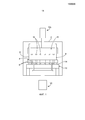
Фиг.1 изображает схематический вид пресса для производства таблеток ядерного топлива, в котором может применяться настоящее изобретение.Figure 1 depicts a schematic view of a press for the production of tablets of nuclear fuel, which can be applied to the present invention.
Фиг.2 - частичное сечение корпуса компенсатора, снабженного верхними штампами, адаптированного к прессу по Фиг.1.Figure 2 is a partial section of the housing of the compensator, equipped with upper dies, adapted to the press of figure 1.
Фиг.3 - фрагмент Фиг.2 в увеличенном масштабе.Figure 3 is a fragment of Figure 2 on an enlarged scale.
Фиг.4А - продольное сечение узла, состоящего из направляющей втулки и гайки, показанной отдельно, в плоскости, отличающейся от показанной на Фиг.3.FIG. 4A is a longitudinal section of an assembly consisting of a guide sleeve and a nut, shown separately, in a plane different from that shown in FIG. 3.
Фиг.4В - детальный вид узла по Фиг.4А.Fig. 4B is a detailed view of the assembly of Fig. 4A.
Фиг.4С - сечение в плоскости А-А на Фиг.4А.Fig. 4C is a section in the plane AA in Fig. 4A.
Фиг.5А и 5В изображают продольные сечения иллюстративных вариантов инструмента для демонтажа узла направляющей втулки и крепежной гайки.5A and 5B depict longitudinal sections of illustrative embodiments of a tool for dismantling a guide sleeve assembly and a fixing nut.
ПОДРОБНОЕ ОПИСАНИЕ ВАРИАНТОВ ОСУЩЕСТВЛЕНИЯ ИЗОБРЕТЕНИЯDETAILED DESCRIPTION OF EMBODIMENTS OF THE INVENTION
На Фиг.1 показан весьма схематический вид пресса для производств таблеток ядерного топлива.Figure 1 shows a very schematic view of a press for the production of tablets of nuclear fuel.
Настоящее изобретение применимо к гидравлическим прессам любого типа и не ограничивается ядерной областью. Оно особенно полезно в областях, где важным критерием является чистота, а также во всех областях, где применяются прессы, поскольку позволяет упростить обслуживание.The present invention is applicable to any type of hydraulic press and is not limited to the nuclear field. It is especially useful in areas where cleanliness is an important criterion, as well as in all areas where presses are used, as it simplifies maintenance.
Пресс по Фиг.1 установлен в замкнутом отсеке 2 типа перчаточной камеры. Он содержит стол 4, поддерживающий пресс-формы 6, установленные с возможностью свободного движения вдоль направляющих колонн 8, нижний привод Vi для перемещения стола 4, фиксированную опору 12 для нижних штампов 14 и подвижную опору 15 для верхних штампов 16, и может перемещаться верхним приводом Vs. Опора 15 образует корпус компенсатора и несет компенсаторы (не показаны) и верхние штампы 16. В показанном примере приводы проходят сквозь стенки отсека 2 с уплотнением.The press of FIG. 1 is installed in a
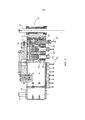
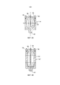
На Фиг.2 показан подробный вид корпуса 15 компенсатора, а на Фиг.3 показан один компенсатор, вставленный в свое отверстие.Figure 2 shows a detailed view of the
Корпус 15 компенсатора образован плитой, внутри которой сформированы отверстия 18 с продольной осью Х, каждое из которых содержит компенсатор 20. В показанном примере отверстия 18 являются сквозными отверстиями, которые заглушены пробкой 22 на одном конце, противоположном концу, из которого выступает компенсатор.The
Каждое отверстие 18 содержит первый участок 18.1 меньшего диаметра и второй участок 18.2 большего диаметра, соединенный с участком 18.1 меньшего диаметра через кольцевую контактную поверхность 18.3. Компенсатор 20 содержит первый участок 20.1 большего диаметра и второй участок 20.2 меньшего диаметра, соединенный с участком 20.1 большего диаметра через уступ 20.3. Участок 20.1 большего диаметра вставлен в участок 18.1 меньшего диаметра отверстия 18.Each
Например, участок 20.1 большего диаметра компенсатора 20 содержит канавку 34, в которую вставлено уплотнение 26, и две канавки 28, расположенные с каждой стороны от канавки 24, в которые вставлены направляющие кольца 30. Преимущественно, в нижней части участка 20.1 большего диаметра компенсатора 20 выполнены два отверстия 29, в каждое из которых вставлен предотвращающий вращение палец 31, закрепленный на дне отверстия 18.For example, the portion 20.1 of the larger diameter of the
Дно каждого отверстия и дно компенсатора, который вставлен в него, определяют камеру 19, которая предназначена для заполнения маслом под давлением. Камеры 19 всех отверстий находятся в гидравлическом сообщении друг с другом, позволяя маслу циркулировать между камерами 19 и уравнивать давление на штампах на этапе прессования.The bottom of each hole and the bottom of the compensator, which is inserted into it, define a
Для заполнения камер используются отводные соединения 19 (Фиг.2), выполненные на передней грани корпуса компенсатора.To fill the chambers, tap connections 19 (FIG. 2) are used, made on the front face of the compensator housing.
В участок 18.2 большего диаметра отверстия 18 вставлена направляющая втулка 32, которая упирается в кольцевую контактную поверхность 18.3. Втулка 32 окружает участок 20.2 меньшего диаметра компенсатора 20. Втулка содержит участок 32.1 большого внешнего диаметра и участок 32.2 малого внешнего диаметра, соединенные через уступ 32.3.A
В показанном примере направляющая втулка 32 содержит два уплотнения 34, расположенные на ее внешней периферии, и два смещенные аксиально уплотняющие средства 35 и направляющий сегмент 36 для компенсатора, расположенный на ее внутренней периферии. Этот направляющий сегмент вставлен в участок 32.2 малого диаметра. Преимущественно, каждое из уплотняющих средств 35 содержит уплотняющее кольцо круглого сечения, установленное радиально на дне канавки, и уплотняющее кольцо на выходе из канавки, которое создает трение с компенсатором. Затем кольцо прижимается к компенсатору кольцевым уплотнением круглого сечения и давлением масла.In the example shown, the
Крепежная гайка 38 установлена в участок 18.2 большего диаметра отверстия 18 и упирается в уступ 32.3 направляющей втулки 32.The fixing
Крепежная гайка 38 содержит участок 38.1 большого внутреннего диаметра и часть 38.2 малого внутреннего диаметра. Крепежная гайка 38 надета на втулку 32 так, что ее участок 381 большого внутреннего диаметра окружает участок 32.2 малого внешнего диаметра направляющей втулки 32.The fixing
Крепежная гайка 38 содержит резьбу 40 на своей внешней периферии, взаимодействующую с резьбой на участке 18.2 большего диаметра. Крепежная гайка оснащена уплотнением 42, расположенным на ее внутренней периферии, например сальником, который создает трение на участке 20.2 малого диаметра компенсатора.The
Между внутренним диаметром участка 38.1 большого диаметра гайки и внешним диаметром участка малого диаметра втулки 32 имеется зазор так, что гайка надета на втулку без натяга.Between the inner diameter of the section 38.1 of the large diameter of the nut and the outer diameter of the section of the small diameter of the
На Фиг.4А приведен вид в сечении узла направляющей втулки 32 и крепежной гайки 38, при этом сечение проходит в плоскости, отличающейся от плоскости, показанной на Фиг.3.FIG. 4A shows a sectional view of the assembly of the
Согласно настоящему изобретению втулка 32 и гайка аксиально и радиально прикреплены друг к другу с сохранением аксиального и радиального зазоров между ними. Между втулкой 32 и гайкой 38 установлено крепежное средство 44 с зазором.According to the present invention, the
В примере, показанном на Фиг.4В и 4С, преимущественно, крепежное средство 44 содержит три радиальных отверстия 46, разнесенных на 120° друг от друга и сформированных на участке малого внутреннего диаметра гайки, и открывающихся в канавку 48, сформированную в периферии участка 32.2 малого внешнего диаметра втулки 32, и в отверстия 46 вставлены пальцы 50, которые проникают в канавку 48. Внешние размеры пальцев и размеры канавки 48 выбраны так, чтобы обеспечить радиальный зазор и осевой зазор. Пальцы 50 установлены с возможностью свободного скольжения в отверстиях 46.In the example shown in FIGS. 4B and 4C, advantageously, the fastening means 44 comprises three
Крепежное средство может содержать два пальца, однако использование трех пальцев снижает риск перекоса гайки относительно втулки.The fastener may contain two fingers, however, using three fingers reduces the risk of the nut skewing relative to the sleeve.
Канавка 48 устраняет необходимость устанавливать гайку под определенным углом относительно втулки. Кроме того, гайка не блокирует вращение втулки. При затягивании и отпускании гайки втулка 32 не вращается вместе с гайкой, поэтому сила к уплотнениям не прилагается.
В показанном примере, преимущественно, поперечное положение пальцев и, следовательно, радиальный зазор регулируется зажимными винтами 52, ввинченными в радиальные отверстия 46 после того, как в них будут вставлены пальцы.In the example shown, the lateral position of the fingers, and therefore the radial clearance, is predominantly adjusted by the clamping screws 52 screwed into the radial holes 46 after the fingers are inserted into them.
Использование зажимных винтов создает дополнительную деталь, на которой имеются дополнительные допуски и, следовательно, зазор. Эта деталь позволяет улучшить аксиальный зазор.The use of clamping screws creates an additional part that has additional tolerances and, therefore, clearance. This part improves axial clearance.
Преимущественно, чтобы не допустить изменения положения пальцев со временем, зажимные винты 52 защищены от вращения, например, с помощью герметика для резьбы или зачеканиванием резьбы. Такое постоянное крепление позволяет очень легко зафиксировать зазоры. Это становится возможным, поскольку втулка и гайка не требуют разделения в течение всего срока службы пресса.Advantageously, in order to prevent the position of the fingers from changing over time, the clamping screws 52 are protected against rotation, for example by thread sealant or thread threading. Such permanent mounting makes it very easy to fix the gaps. This becomes possible because the sleeve and nut do not require separation throughout the life of the press.
Преимущественно, конец пальцев 50, входящий в кольцевую канавку 48, имеет концевой участок уменьшенного диаметра, который может ограничить размер кольцевой канавки 48 так, чтобы не ввести во втулку 32 точки ослабления. Этот конец с сечением уменьшенного диаметра образует неограничивающую направляющую для уплотнений втулки 32 во время установки узла втулки 32 и гайки 38 в отверстие корпуса компенсатора. В заблокированном положении контактные поверхности деталей 32 и 38 оказывают сопротивление силе затягивания на контактной поверхности 57 на Фиг.4А.Advantageously, the end of the
Например имеется радиальный зазор между втулкой 38 и гайкой 37, равный 0,045 и 0,355 мм. Когда зажимные винты 52 установлены на место, их затяжку регулируют так, чтобы сохранить радиальный зазор в пределах 0,05 и 0,139 мм.For example, there is a radial clearance between
Поэтому когда гайка 38 отвинчена, втулка 32 извлекается.Therefore, when the
Эти крепежные средства также имеют преимущество, заключающееся в том, что они не мешают уплотнению компенсатора.These fasteners also have the advantage that they do not interfere with the seal of the compensator.
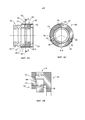
На Фиг.5А и 5В показан специально адаптированный инструмент для затяжки/отпускания крепежной гайки 38, когда штамп не установлен на компенсаторе 20. Инструмент 54 содержит средство для приведения гайки во вращение в направлении затягивания или отпускания.5A and 5B show a specially adapted tool for tightening / loosening the mounting
В показанном примере инструмент 54 содержит кольцевую грань 56 на первом продольном конце, которая имеет три выступающих пальца 58, проходящих продольно. Пальцы 58 предназначены для входа в три ответных отверстия 59, выполненные в одной грани крепежной гайки 38, ориентированной наружу от отверстия 18. Например, пальцы 58 сформированы штифтами, вставленными в отверстия в поперечной грани 56. Инструмент содержит по меньшей мере два пальца и, предпочтительно, три пальца.In the example shown, the
Инструмент 54 также содержит центральную полость 60, ограниченную кольцевой гранью 56. Полость 60 выполнена с возможностью принимать выступающий конец компенсатора 20.The
Инструмент 54 содержит метку 62 на одном продольном конце, который противоположен концу, на котором установлены пальцы и который предназначен для крепления к рычагу, способному прилагать крутящий момент к инструменту, направленный вокруг его продольной оси. В показанном примере метка 62 является шестигранным выступом, и инструмент является рукояткой с храповиком. Как вариант, метка может быть шестигранным или квадратным углублением и т.п., рычаг крепится под конкретным углом к инструменту 54 и момент, приложенный к рычагу, приводит к вращению инструмента.The
Преимущественно, боковая стенка центральной полости 60 выполнена перфорированной для уменьшения массы инструмента 54. На время операций сборки и разборки такой инструмент удерживается на расстоянии вытянутой руки.Advantageously, the side wall of the
Как вариант, можно представить, что крепежная гайка содержит выступающие пальцы, а инструмент - соответствующие углубления.Alternatively, you can imagine that the mounting nut contains protruding fingers, and the tool contains the corresponding recesses.
На Фиг.5В инструмент 54' подобен инструменту 54, однако он адаптирован для затяжки/отпускания крепежной гайки 38, когда на компенсаторе 20 установлен штамп. Для этого центральная полость 60 выполнена более глубокой, чтобы вмещать компенсатор и штамп.5B, the tool 54 'is similar to the
Далее следует описание операции разборки и сборки компенсатора с использованием узла втулки и гайки.The following is a description of the operation of disassembling and assembling the compensator using the hub and nut assembly.
Уплотнения компенсатора проверяют во время операции по техническому обслуживанию пресса, во время которой верхние штампы снимают с компенсаторов.Compensator seals are checked during a press maintenance operation, during which the upper dies are removed from the compensators.
Инструмент 54 устанавливают вокруг штампа и ориентируют так, чтобы пальцы 58 были обращены к отверстиям в гайке. Затем инструмент подводят в осевом направлении к гайке и пальцы вставляют в отверстия. К инструменту 54 прилагают крутящий момент в направлении отпускания гайки 38. Гайка 38 поворачивается и отвинчивается. Почти одновременно втулка 32 гайки передает вращение и осевое перемещение на втулку 32 и происходит смещение втулки 32 с небольшой задержкой, вызванной выбиранием радиальных и аксиальных зазоров.A
Гайку 38 и втулку 32 извлекают. Затем из отверстия 18 извлекают компенсатор, прилагая к нему тянущее усилие.
Проверяют и при необходимости заменяют уплотнения.Check and, if necessary, replace the seals.
Во время сборки компенсатор 20 вставляют в отверстие 18, преимущественно, используя гильзу (не показана). Компенсатор ориентируют так, чтобы предотвращающий вращение палец, прикрепленный к дну отверстия, проник в отверстие в компенсаторе.During assembly, the
Затем в отверстие 18 вставляют узел втулки 32 и гайки 38 так, чтобы он располагался вокруг компенсатора. Втулку 32 вставляют с особой осторожностью, чтобы не повредить уплотнения. Затем гайку 38 ввинчивают в отверстие, так, чтобы она поджимала втулку 32 в осевом направлении до упора в кольцевую контактную поверхность в отверстии. Благодаря радиальному зазору и осевому зазору втулку 32 можно позиционировать на компенсаторе 20 и в отверстии 18, не повреждая уплотнения.Then, the
Настоящее изобретение упрощает обслуживание прессов и, более конкретно, компенсаторов за счет упрощения разборки направляющей втулки и защите уплотнений во время сборки втулки.The present invention simplifies the maintenance of presses and, more specifically, expansion joints by simplifying disassembly of the guide sleeve and protecting seals during assembly of the sleeve.
Claims (11)
- направляющую втулку (32) для компенсатора (20), которая расположена в предусмотренном для компенсатора отверстии (18) и выполнена с возможностью установки вокруг компенсатора (20);
- крепежную гайку (38), выполненную с возможностью ввинчивания в упомянутое отверстие (18), при этом направляющая втулка (32) расположена между уступом (20.3), выполненном на компенсаторе (20), и крепежной гайкой (38); и
- средство (44) для осевой фиксации направляющей втулки (32) и крепежной гайки (38) с сохранением осевого и поперечного зазоров между направляющей втулкой (32) и крепежной гайкой (38), при этом средство (44) выполнено с обеспечением возможности свободного вращения направляющей втулки (32) относительно крепежной гайки (38).1. The guide and mounting unit of the press compensator, comprising:
- a guide sleeve (32) for the compensator (20), which is located in the hole provided for the compensator (18) and is configured to be installed around the compensator (20);
- a fixing nut (38), made with the possibility of screwing into the aforementioned hole (18), while the guide sleeve (32) is located between the ledge (20.3) made on the expansion joint (20) and the fixing nut (38); and
- means (44) for axial fixing of the guide sleeve (32) and the fixing nut (38) while maintaining the axial and transverse gaps between the guide sleeve (32) and the fixing nut (38), while the tool (44) is made with the possibility of free rotation guide sleeve (32) relative to the mounting nut (38).
- стол (4), снабженный по меньшей мере двумя пресс-формами (6),
- штампы (16), продольная ось которых расположена с обеспечением проникновения их в пресс-формы,
- опору (15) штампов, которая выполнена с возможностью перемещения приводом (Vs) для подвода штампов (16) к пресс-формам (6) в продольном направлении,
- компенсаторы (20), соединенные с каждым штампом (16), при этом каждый компенсатор имеет продольную ось, установлен с уплотнением в отверстии (18) в опоре (15) и содержит первый продольный конец, предназначенный для воздействия на него гидравлического давления, и второй продольный конец, несущий штамп (16), при этом отверстия (18) расположены с гидравлическим сообщением друг с другом, и
- направляющие и крепежные узлы компенсаторов по одному из пп.1-9, вставленные в каждое из отверстий (18).10. A press containing:
- a table (4) provided with at least two molds (6),
- dies (16), the longitudinal axis of which is located with ensuring their penetration into the mold,
- the support (15) of the dies, which is made with the possibility of movement by the drive (Vs) for the supply of dies (16) to the molds (6) in the longitudinal direction,
- compensators (20) connected to each stamp (16), with each compensator having a longitudinal axis, installed with a seal in the hole (18) in the support (15) and contains a first longitudinal end designed to exert hydraulic pressure on it, and the second longitudinal end bearing the stamp (16), while the holes (18) are located in hydraulic communication with each other, and
- guiding and fixing nodes of compensators according to one of claims 1 to 9, inserted into each of the holes (18).
Applications Claiming Priority (3)
| Application Number | Priority Date | Filing Date | Title |
|---|---|---|---|
| FR1152412A FR2972957B1 (en) | 2011-03-23 | 2011-03-23 | IMPROVED MAINTENANCE PRESS |
| FR1152412 | 2011-03-23 | ||
| PCT/EP2012/054954 WO2012126930A1 (en) | 2011-03-23 | 2012-03-21 | Press having improved support |
Publications (2)
| Publication Number | Publication Date |
|---|---|
| RU2013147167A RU2013147167A (en) | 2015-04-27 |
| RU2591921C2 true RU2591921C2 (en) | 2016-07-20 |
Family
ID=45908031
Family Applications (1)
| Application Number | Title | Priority Date | Filing Date |
|---|---|---|---|
| RU2013147167/02A RU2591921C2 (en) | 2011-03-23 | 2012-03-21 | Press with improved service |
Country Status (7)
| Country | Link |
|---|---|
| US (1) | US9114584B2 (en) |
| EP (1) | EP2688741B1 (en) |
| JP (1) | JP5950134B2 (en) |
| CN (1) | CN103442885B (en) |
| FR (1) | FR2972957B1 (en) |
| RU (1) | RU2591921C2 (en) |
| WO (1) | WO2012126930A1 (en) |
Families Citing this family (7)
| Publication number | Priority date | Publication date | Assignee | Title |
|---|---|---|---|---|
| FR3021805B1 (en) * | 2014-05-27 | 2019-05-03 | Commissariat A L'energie Atomique Et Aux Energies Alternatives | PRESS FOR SHAPING PELLETS IN A RESTRICTED AND HOSTILE ENVIRONMENT AND METHOD OF ASSEMBLING THE PRESS |
| US10303438B2 (en) | 2017-01-16 | 2019-05-28 | International Business Machines Corporation | Fused-multiply-add floating-point operations on 128 bit wide operands |
| DE102018112476B4 (en) | 2017-06-02 | 2022-01-27 | Ulrich Lang | Method and production plant for producing a foil substrate |
| US10241756B2 (en) | 2017-07-11 | 2019-03-26 | International Business Machines Corporation | Tiny detection in a floating-point unit |
| NL2019767B1 (en) * | 2017-10-20 | 2019-04-29 | Besi Netherlands Bv | Press part for supporting a mould part for encapsulating electronic components mounted on a carrier and a press comprising the press part |
| WO2019224364A1 (en) | 2018-05-24 | 2019-11-28 | Ulrich Lang | Method and production installation for producing a film substrate |
| CN113954413A (en) * | 2021-09-30 | 2022-01-21 | 中国原子能科学研究院 | A press for sealing in shielding glove box |
Citations (4)
| Publication number | Priority date | Publication date | Assignee | Title |
|---|---|---|---|---|
| SU50474A1 (en) * | 1936-06-23 | 1936-11-30 | П.С. Лапшин | Hydraulic compensator to presses |
| FR1206366A (en) * | 1958-08-13 | 1960-02-09 | Hydrel | Process for mounting various components, in particular jack caps at the end of cylinders and tubes |
| SU667416A1 (en) * | 1977-11-10 | 1979-06-15 | Zenchenko Vladimir P | Pressing apparatus |
| US4323003A (en) * | 1980-03-24 | 1982-04-06 | Clippard Instrument Laboratory, Inc. | Fluid cylinder with replaceable rod seal and guide |
Family Cites Families (13)
| Publication number | Priority date | Publication date | Assignee | Title |
|---|---|---|---|---|
| US2569226A (en) * | 1946-01-11 | 1951-09-25 | Denison Eng Co | Method of producing articles from powdered material |
| GB1385028A (en) * | 1971-11-23 | 1975-02-26 | Coopers Metals Ltd | Briquetting presses |
| US3890413A (en) * | 1974-08-15 | 1975-06-17 | Hydramet American Inc | Apparatus and method for compacting particulate materials |
| GB2047142A (en) | 1978-11-27 | 1980-11-26 | Loepfe Automation | Press comprising at least one reciprocating tool |
| US5934165A (en) * | 1997-03-19 | 1999-08-10 | Strippit, Inc. | Adjustable punch assembly |
| JP2000094196A (en) * | 1998-09-18 | 2000-04-04 | Daidoo Denshi:Kk | Compression molding device for powder |
| US6276247B1 (en) * | 2000-03-03 | 2001-08-21 | Strippit, Inc. | Adjustable punch assembly with releasable locking |
| US6755110B2 (en) * | 2001-06-19 | 2004-06-29 | Wilson Tool International, Inc. | Adjustable length punch assembly |
| JP2005262239A (en) * | 2004-03-16 | 2005-09-29 | Toyota Motor Corp | Powder molding die |
| US8714065B2 (en) * | 2004-11-19 | 2014-05-06 | Amada Company, Limited | Punching die |
| US7658134B2 (en) * | 2005-09-29 | 2010-02-09 | Mate Precision Tooling, Inc. | Punch with self-contained punch recess adjustment indexing |
| JP2007098460A (en) * | 2005-10-07 | 2007-04-19 | Sumitomo Denko Shoketsu Gokin Kk | Press die for powder molding |
| US8348249B2 (en) | 2008-10-07 | 2013-01-08 | Dadco, Inc. | Reaction device for forming equipment |
-
2011
- 2011-03-23 FR FR1152412A patent/FR2972957B1/en not_active Expired - Fee Related
-
2012
- 2012-03-21 EP EP12711140.9A patent/EP2688741B1/en active Active
- 2012-03-21 US US14/006,382 patent/US9114584B2/en not_active Expired - Fee Related
- 2012-03-21 CN CN201280014732.5A patent/CN103442885B/en active Active
- 2012-03-21 WO PCT/EP2012/054954 patent/WO2012126930A1/en active Application Filing
- 2012-03-21 JP JP2014500361A patent/JP5950134B2/en active Active
- 2012-03-21 RU RU2013147167/02A patent/RU2591921C2/en not_active IP Right Cessation
Patent Citations (4)
| Publication number | Priority date | Publication date | Assignee | Title |
|---|---|---|---|---|
| SU50474A1 (en) * | 1936-06-23 | 1936-11-30 | П.С. Лапшин | Hydraulic compensator to presses |
| FR1206366A (en) * | 1958-08-13 | 1960-02-09 | Hydrel | Process for mounting various components, in particular jack caps at the end of cylinders and tubes |
| SU667416A1 (en) * | 1977-11-10 | 1979-06-15 | Zenchenko Vladimir P | Pressing apparatus |
| US4323003A (en) * | 1980-03-24 | 1982-04-06 | Clippard Instrument Laboratory, Inc. | Fluid cylinder with replaceable rod seal and guide |
Also Published As
| Publication number | Publication date |
|---|---|
| RU2013147167A (en) | 2015-04-27 |
| FR2972957A1 (en) | 2012-09-28 |
| CN103442885B (en) | 2015-08-12 |
| CN103442885A (en) | 2013-12-11 |
| EP2688741B1 (en) | 2019-04-10 |
| US20140004220A1 (en) | 2014-01-02 |
| EP2688741A1 (en) | 2014-01-29 |
| WO2012126930A1 (en) | 2012-09-27 |
| US9114584B2 (en) | 2015-08-25 |
| JP5950134B2 (en) | 2016-07-13 |
| FR2972957B1 (en) | 2014-02-21 |
| JP2014514160A (en) | 2014-06-19 |
Similar Documents
| Publication | Publication Date | Title |
|---|---|---|
| RU2591921C2 (en) | Press with improved service | |
| KR20090008192A (en) | Robotic tool changer | |
| US20080157451A1 (en) | Positioning apparatus and clamping system having the same | |
| US20170292642A1 (en) | Manual quick connect hub clamping system | |
| US20170299070A1 (en) | Top entry trunnion ball valve suitable for safe in-line maintenance and method to facilitate such maintenance | |
| US7793924B2 (en) | Positioning device and clamping system with the device | |
| SG189925A1 (en) | Mechanical seal | |
| WO2007043143A1 (en) | Liquid pressure device | |
| KR100801245B1 (en) | Hydraulic cylinder and a method for assembling thereof | |
| JP5666460B2 (en) | Screw engagement type clamping device, clamping system, and fluid pressure actuator | |
| CN101936392B (en) | Sealing device for cylinder plunger | |
| US20030031287A1 (en) | Seal arrangement for in-core instrument housing | |
| KR20170018431A (en) | Sealing device | |
| JPH08193610A (en) | Locking bar and locking nut | |
| US10245689B2 (en) | Rod tensioning device and assembly process of such a device on a rod | |
| CN103032441B (en) | Locking device | |
| JP4483848B2 (en) | Cylinder block machining method and machining apparatus | |
| JP2023122774A (en) | Water leakage prevention device | |
| CN212201880U (en) | Inner sleeve inserted type top driving device | |
| KR200473036Y1 (en) | Stem fixture of large size butterfly valve | |
| JP5014097B2 (en) | Packing follower removal tool | |
| JP6715178B2 (en) | Method for attaching and detaching valve operating device and valve device | |
| KR100914595B1 (en) | Fastening jig for piston rod | |
| CN204458769U (en) | Locking device | |
| CN116480279A (en) | Non-excavation pilot drill |
Legal Events
| Date | Code | Title | Description |
|---|---|---|---|
| MM4A | The patent is invalid due to non-payment of fees |
Effective date: 20210322 |