RU2589974C1 - Fitting, system containing such fitting, and airtight connection with such fitting - Google Patents
Fitting, system containing such fitting, and airtight connection with such fitting Download PDFInfo
- Publication number
- RU2589974C1 RU2589974C1 RU2015112143/06A RU2015112143A RU2589974C1 RU 2589974 C1 RU2589974 C1 RU 2589974C1 RU 2015112143/06 A RU2015112143/06 A RU 2015112143/06A RU 2015112143 A RU2015112143 A RU 2015112143A RU 2589974 C1 RU2589974 C1 RU 2589974C1
- Authority
- RU
- Russia
- Prior art keywords
- fitting
- supporting part
- circumferential surface
- tubular end
- tubular
- Prior art date
Links
Images
Classifications
-
- F—MECHANICAL ENGINEERING; LIGHTING; HEATING; WEAPONS; BLASTING
- F16—ENGINEERING ELEMENTS AND UNITS; GENERAL MEASURES FOR PRODUCING AND MAINTAINING EFFECTIVE FUNCTIONING OF MACHINES OR INSTALLATIONS; THERMAL INSULATION IN GENERAL
- F16L—PIPES; JOINTS OR FITTINGS FOR PIPES; SUPPORTS FOR PIPES, CABLES OR PROTECTIVE TUBING; MEANS FOR THERMAL INSULATION IN GENERAL
- F16L13/00—Non-disconnectible pipe-joints, e.g. soldered, adhesive or caulked joints
- F16L13/14—Non-disconnectible pipe-joints, e.g. soldered, adhesive or caulked joints made by plastically deforming the material of the pipe, e.g. by flanging, rolling
- F16L13/141—Non-disconnectible pipe-joints, e.g. soldered, adhesive or caulked joints made by plastically deforming the material of the pipe, e.g. by flanging, rolling by crimping or rolling from the outside
-
- F—MECHANICAL ENGINEERING; LIGHTING; HEATING; WEAPONS; BLASTING
- F16—ENGINEERING ELEMENTS AND UNITS; GENERAL MEASURES FOR PRODUCING AND MAINTAINING EFFECTIVE FUNCTIONING OF MACHINES OR INSTALLATIONS; THERMAL INSULATION IN GENERAL
- F16L—PIPES; JOINTS OR FITTINGS FOR PIPES; SUPPORTS FOR PIPES, CABLES OR PROTECTIVE TUBING; MEANS FOR THERMAL INSULATION IN GENERAL
- F16L13/00—Non-disconnectible pipe-joints, e.g. soldered, adhesive or caulked joints
- F16L13/14—Non-disconnectible pipe-joints, e.g. soldered, adhesive or caulked joints made by plastically deforming the material of the pipe, e.g. by flanging, rolling
- F16L13/146—Non-disconnectible pipe-joints, e.g. soldered, adhesive or caulked joints made by plastically deforming the material of the pipe, e.g. by flanging, rolling by an axially moveable sleeve
-
- F—MECHANICAL ENGINEERING; LIGHTING; HEATING; WEAPONS; BLASTING
- F16—ENGINEERING ELEMENTS AND UNITS; GENERAL MEASURES FOR PRODUCING AND MAINTAINING EFFECTIVE FUNCTIONING OF MACHINES OR INSTALLATIONS; THERMAL INSULATION IN GENERAL
- F16L—PIPES; JOINTS OR FITTINGS FOR PIPES; SUPPORTS FOR PIPES, CABLES OR PROTECTIVE TUBING; MEANS FOR THERMAL INSULATION IN GENERAL
- F16L19/00—Joints in which sealing surfaces are pressed together by means of a member, e.g. a swivel nut, screwed on or into one of the joint parts
- F16L19/06—Joints in which sealing surfaces are pressed together by means of a member, e.g. a swivel nut, screwed on or into one of the joint parts in which radial clamping is obtained by wedging action on non-deformed pipe ends
- F16L19/065—Joints in which sealing surfaces are pressed together by means of a member, e.g. a swivel nut, screwed on or into one of the joint parts in which radial clamping is obtained by wedging action on non-deformed pipe ends the wedging action being effected by means of a ring
-
- F—MECHANICAL ENGINEERING; LIGHTING; HEATING; WEAPONS; BLASTING
- F16—ENGINEERING ELEMENTS AND UNITS; GENERAL MEASURES FOR PRODUCING AND MAINTAINING EFFECTIVE FUNCTIONING OF MACHINES OR INSTALLATIONS; THERMAL INSULATION IN GENERAL
- F16L—PIPES; JOINTS OR FITTINGS FOR PIPES; SUPPORTS FOR PIPES, CABLES OR PROTECTIVE TUBING; MEANS FOR THERMAL INSULATION IN GENERAL
- F16L33/00—Arrangements for connecting hoses to rigid members; Rigid hose connectors, i.e. single members engaging both hoses
- F16L33/20—Undivided rings, sleeves or like members contracted on the hose or expanded in the hose by means of tools; Arrangements using such members
- F16L33/207—Undivided rings, sleeves or like members contracted on the hose or expanded in the hose by means of tools; Arrangements using such members only a sleeve being contracted on the hose
- F16L33/2071—Undivided rings, sleeves or like members contracted on the hose or expanded in the hose by means of tools; Arrangements using such members only a sleeve being contracted on the hose the sleeve being a separate connecting member
-
- F—MECHANICAL ENGINEERING; LIGHTING; HEATING; WEAPONS; BLASTING
- F16—ENGINEERING ELEMENTS AND UNITS; GENERAL MEASURES FOR PRODUCING AND MAINTAINING EFFECTIVE FUNCTIONING OF MACHINES OR INSTALLATIONS; THERMAL INSULATION IN GENERAL
- F16L—PIPES; JOINTS OR FITTINGS FOR PIPES; SUPPORTS FOR PIPES, CABLES OR PROTECTIVE TUBING; MEANS FOR THERMAL INSULATION IN GENERAL
- F16L37/00—Couplings of the quick-acting type
- F16L37/08—Couplings of the quick-acting type in which the connection between abutting or axially overlapping ends is maintained by locking members
- F16L37/12—Couplings of the quick-acting type in which the connection between abutting or axially overlapping ends is maintained by locking members using hooks, pawls or other movable or insertable locking members
- F16L37/138—Couplings of the quick-acting type in which the connection between abutting or axially overlapping ends is maintained by locking members using hooks, pawls or other movable or insertable locking members using an axially movable sleeve
Landscapes
- Engineering & Computer Science (AREA)
- General Engineering & Computer Science (AREA)
- Mechanical Engineering (AREA)
- Quick-Acting Or Multi-Walled Pipe Joints (AREA)
- Earth Drilling (AREA)
- Joints With Sleeves (AREA)
- Hooks, Suction Cups, And Attachment By Adhesive Means (AREA)
- Insertion Pins And Rivets (AREA)
- Toys (AREA)
Abstract
Description
Изобретение относится к фитингу для герметичного соединения трубчатых концов, в частности труб. Изобретение также относится к системе, содержащей такой фитинг и наружную муфту, и к герметичному соединению, содержащему такой фитинг и трубчатый конец.The invention relates to a fitting for hermetically connecting tubular ends, in particular pipes. The invention also relates to a system containing such a fitting and an external sleeve, and to a sealed connection containing such a fitting and a tubular end.
Как известно, в существующем уровне техники трубчатые концы соединяют посредством фитингов. В этом случае трубчатыми концами могут быть либо концы труб, либо концы других элементов, например элементов монтажной арматуры. Посредством фитингов можно соединять трубы друг с другом или соединять трубы с другими элементами, например с вентилями, клапанными элементами и т.д. Кроме того, фитинги также могут быть выполнены, например, в виде Т-образных деталей.As is known, in the prior art, tubular ends are connected by means of fittings. In this case, the tubular ends can be either the ends of the pipes or the ends of other elements, for example, elements of mounting fittings. By means of fittings, it is possible to connect pipes to each other or to connect pipes to other elements, for example, valves, valve elements, etc. In addition, the fittings can also be made, for example, in the form of T-shaped parts.
Для создания герметичных соединений, что является особенно важным в области газовых труб или труб для жидкости, например водопроводных труб, в частности, для питьевых водопроводов, предпочтительно использовать фитинги. В этом случае, однако, должны выполняться жесткие требования по герметичности соединений для обеспечения их постоянной герметичности. Если транспортируемой по трубе средой является газ, трубное соединение должно выдерживать давление до 10 бар при изменении температуры от -20°C до +60°C в течение нескольких дней. Если транспортируемой средой является вода, соединение должно выдерживать изменения температуры от комнатной или от температуры холодной воды до 95°C, а также должны быть максимально коррозионно-устойчивыми.To create a tight connection, which is especially important in the field of gas pipes or pipes for liquids, such as water pipes, in particular for drinking water pipes, it is preferable to use fittings. In this case, however, the stringent tightness requirements of the joints must be met to ensure their constant tightness. If the medium transported through the pipe is gas, the pipe connection must withstand pressure up to 10 bar when the temperature changes from -20 ° C to + 60 ° C for several days. If the transported medium is water, the joint must withstand temperature changes from room temperature or from cold water to 95 ° C, and must also be as corrosion-resistant as possible.
Несмотря на то, что в течение длительного времени в качестве материала для труб и их элементов использовали металл, в настоящее время трубы и их элементы постоянно производят (по меньшей мере, частично) из пластмассы. В частности, содержащие пластмассу трубы часто применяют в виде композитных труб или многослойных композитных труб. Однако это приводит к возникновению проблем соединения трубчатых концов, также содержащих пластмассу, с фитингами, которые по-прежнему производятся из металла.Despite the fact that for a long time metal was used as a material for pipes and their elements, now pipes and their elements are constantly produced (at least partially) from plastic. In particular, plastic-containing pipes are often used in the form of composite pipes or multilayer composite pipes. However, this leads to problems in connecting the tubular ends, also containing plastic, with fittings that are still made of metal.
Как правило, пластмасса трубчатых концов имеет более высокую гибкость, чем металл фитингов. Таким образом, например, в случае деформации пластмасса может возвратиться обратно к своему исходному состоянию, в то время как металл не сможет деформироваться или его деформация будет необратимой. По этой причине при использовании металлического фитинга для трубчатого конца, содержащего пластмассу, бывает трудно получить постоянно герметичное соединение между фитингом и трубчатым концом.Typically, plastic tubular ends have higher flexibility than metal fittings. Thus, for example, in the case of deformation, the plastic can return back to its original state, while the metal cannot be deformed or its deformation is irreversible. For this reason, when using a metal fitting for a tubular end containing plastic, it can be difficult to obtain a permanently tight connection between the fitting and the tubular end.
В известном уровне техники эту проблему решали путем применения так называемых уплотнительных элементов, например уплотнительных колец. Для этого уплотнительный элемент помещали между внешней окружной поверхностью фитинга и внутренней окружной поверхностью трубчатого конца (внутреннее уплотнение) или между внутренней окружной поверхностью фитинга и внешней окружной поверхностью трубчатого конца (внешнее уплотнение). Гибкость уплотнительного элемента может компенсировать недостаток гибкости металлического фитинга.In the prior art, this problem was solved by the use of so-called sealing elements, for example, sealing rings. For this, the sealing element was placed between the outer circumferential surface of the fitting and the inner circumferential surface of the tubular end (inner seal) or between the inner circumferential surface of the fitting and the outer circumferential surface of the tubular end (outer seal). The flexibility of the sealing element can compensate for the lack of flexibility of the metal fitting.
Однако проблематичным в этом отношении является то, что, с одной стороны, необходимо дополнительное внимание при установке или монтаже, например, чтобы уплотнительный элемент не соскользнул. При использовании таких уплотнительных элементов могут происходить случайные утечки.However, it is problematic in this regard that, on the one hand, additional attention is required during installation or installation, for example, so that the sealing element does not slip. When using such sealing elements, accidental leaks can occur.
С другой стороны, при применении фитингов для элементов, предназначенных для транспортировки газа, а также воды, вследствие различного влияния данных сред на гибкие уплотнительные элементы, необходимо использовать дополнительные уплотнительные элементы или даже другие фитинги. Это порождает дальнейшие неудобства, такие как необходимость использования более сложной технологии производства или обеспечения большой осторожности при монтаже вследствие необходимости применения других уплотнительных элементов или фитингов, в зависимости от транспортируемой среды.On the other hand, when using fittings for elements designed to transport gas and water, due to the different effects of these media on flexible sealing elements, it is necessary to use additional sealing elements or even other fittings. This causes further inconvenience, such as the need to use a more complex production technology or to ensure great care during installation due to the need to use other sealing elements or fittings, depending on the transported medium.
Как известно из предшествующего уровня техники, при использовании внутреннего уплотнения фитингов сначала производят расширение трубчатого конца содержащей пластмассу трубы, а затем осуществляют соединение трубы с фитингом посредством надевания трубы на фитинг. Таким образом, при восстановлении усилия, действующего радиально внутрь со стороны трубчатого конца на фитинг, может быть получено достаточное уплотнение. Недостатком данного метода является то, что, с одной стороны, необходимо выполнять дополнительную операцию по расширению трубчатого конца, и с другой стороны, материал трубчатого конца при расширении подвергается воздействию значительного напряжения, что может приводить к разделению слоев, в частности, при использовании композитных или многослойных композитных труб.As is known from the prior art, when using the internal seal of the fittings, the tubular end of the pipe containing the plastic is expanded first, and then the pipe is connected to the fitting by putting the pipe on the fitting. Thus, when restoring the force acting radially inward from the tubular end to the fitting, a sufficient seal can be obtained. The disadvantage of this method is that, on the one hand, it is necessary to perform an additional operation to expand the tubular end, and on the other hand, the material of the tubular end is subjected to significant stress during expansion, which can lead to separation of the layers, in particular, when using composite or multilayer composite pipes.
Существует теоретическая возможность отказаться от использования металлических фитингов и перейти к использованию фитингов, выполненных полностью из пластмассы. Однако восприятие рынком таких фитингов является недостаточным для замещения металлических фитингов. Кроме того, металлические фитинги могут обеспечивать более высокую стабильность соединения.There is a theoretical possibility to abandon the use of metal fittings and switch to the use of fittings made entirely of plastic. However, market acceptance of such fittings is insufficient to replace metal fittings. In addition, metal fittings can provide higher joint stability.
Исходя из этого, технической задачей изобретения является создание фитинга, способного обеспечивать достаточное уплотнение трубчатого конца, при устранении в то же время вышеуказанных проблем. Кроме того, изобретение направлено на создание системы и герметичного соединения, содержащих такой фитинг.Based on this, the technical task of the invention is to provide a fitting capable of providing sufficient sealing of the tubular end, while at the same time eliminating the above problems. In addition, the invention is directed to a system and an airtight connection containing such a fitting.
Задача решается фитингом для герметичного соединения трубчатого конца, в частности трубы, согласно первому объекту изобретения, содержащим внешний трубчатый корпус фитинга, включающий в себя внешнюю опорную часть, выполненную, по меньшей мере, частично из пластмассы и предназначенную для вставки в трубчатый конец, и внутренний трубчатый корпус фитинга, включающий в себя внутреннюю опорную часть, выполненную, по меньшей мере, частично из металла и предназначенную для вставки в трубчатый конец, причем внутренняя опорная часть расположена, по меньшей мере, частично внутри внешней опорной части, внутренняя окружная поверхность внешней опорной части и внешняя окружная поверхность внутренней опорной части уплотнены относительно друг друга в областях и между внутренней окружной поверхностью внешней опорной части и внешней окружной поверхностью внутренней опорной части выполнена, по меньшей мере, одна полость.The problem is solved by a fitting for hermetically connecting a tubular end, in particular a pipe, according to a first aspect of the invention, comprising an external tubular body of the fitting including an external support part made at least partially of plastic and intended to be inserted into the tubular end, and the inner a tubular fitting body including an inner support portion made at least partially of metal and intended to be inserted into the tubular end, wherein the inner support portion is located at least partially inside the outer supporting part, the inner circumferential surface of the outer supporting part and the outer circumferential surface of the inner supporting part are sealed relative to each other in the regions and between the inner circumferential surface of the outer supporting part and the outer circumferential surface of the inner supporting part one cavity.
Под опорной частью в данном случае подразумевается часть соответствующего корпуса фитинга, которая может быть вставлена в трубчатый конец и которая, следовательно, может поддерживать трубчатый конец изнутри. В этом смысле опорная часть представляет собой внутреннюю опорную часть или внутреннюю опорную часть корпуса. Корпус фитинга, однако, может содержать и другие части, примыкающие к опорным частям, например переходную или основную части, а также дополнительные опорные части, используемые для соединения с другими элементами.Under the supporting part in this case means the part of the corresponding fitting body, which can be inserted into the tubular end and which, therefore, can support the tubular end from the inside. In this sense, the support part is an internal support part or an internal support part of the housing. The fitting body, however, may contain other parts adjacent to the supporting parts, for example, transitional or main parts, as well as additional supporting parts used for connection with other elements.
Технический эффект, обеспечиваемый изобретением, заключается в том, что опорная часть, выполненная, по меньшей мере, частично из пластмассы, перекрывается, по меньшей мере, частично, как показано в радиальном направлении, с опорной частью, выполненной, по меньшей мере, частично из металла, поскольку внутренняя опорная часть расположена, по меньшей мере, частично внутри внешней опорной части. Эти опорные части могут быть вставлены затем в трубчатый конец. Предпочтительно внутренняя опорная часть в этом случае в целом расположена соосно внутри внешней опорной части.The technical effect provided by the invention lies in the fact that the supporting part made at least partially of plastic overlaps at least partially, as shown in the radial direction, with the supporting part made at least partially of metal, since the inner support part is located at least partially inside the outer support part. These support parts can then be inserted into the tubular end. Preferably, the inner support portion in this case is generally aligned coaxially within the outer support portion.
Тот факт, что внутренняя окружная поверхность внешней опорной части и внешняя окружная поверхность внутренней опорной части уплотнены относительно друг друга в областях, предотвращает возможность прохождения транспортируемой по трубопроводу среды (в частности, газа и воды) между внутренней окружной поверхностью внешней опорной части и внешней окружной поверхностью внутренней опорной части.The fact that the inner circumferential surface of the outer supporting part and the outer circumferential surface of the inner supporting part are sealed relative to each other in the regions prevents the passage of the medium transported by the pipeline (in particular gas and water) between the inner circumferential surface of the outer supporting part and the outer circumferential surface internal support part.
Уплотнение фитинга относительно трубчатого конца может осуществляться между внутренней окружной поверхностью трубчатого конца и внешней окружной поверхностью внешней опорной части.The seal of the fitting relative to the tubular end may be between the inner circumferential surface of the tubular end and the outer circumferential surface of the outer support portion.
Эффект, достигаемый за счет того, что между внутренней окружной поверхностью внешней опорной части и внешней окружной поверхностью внутренней опорной части выполнена, по меньшей мере, одна полость, заключается в том, что, несмотря на использование корпуса фитинга, выполненного из металла, может быть получено герметичное соединение с трубчатым концом, даже если трубчатый конец выполнен, по меньшей мере, частично из материала, обладающего гибкостью и упругостью, обеспечить герметичное соединение которого с металлическим фитингом ранее не представлялось возможным. Поскольку, по меньшей мере, одна вышеупомянутая полость обеспечивает пространство, необходимое для радиальной деформации внутрь внешней опорной части, гибкость внешней опорной части, выполненной, по меньшей мере, частично из пластмассы, изменяется таким образом, что она может компенсировать возможную упругую деформацию трубчатого конца, так что сохраняется герметичность уплотнения между внутренней окружной поверхностью трубчатого конца и внешней окружной поверхностью внешней опорной части. Гибкость внешней опорной части в таком случае может обеспечиваться, в частности, с одной стороны, изгибающими усилиями и, с другой стороны, кольцевым напряжением пластмассы внешней опорной части.The effect achieved due to the fact that at least one cavity is made between the inner circumferential surface of the outer supporting part and the outer circumferential surface of the inner supporting part is that, despite the use of a fitting body made of metal, can be obtained a tight connection with the tubular end, even if the tubular end is made at least partially of a material having flexibility and elasticity, to ensure a tight connection which with a metal fitting previously not seemed possible. Since at least one of the aforementioned cavities provides the space necessary for radial deformation inwardly of the outer supporting part, the flexibility of the outer supporting part made at least partially of plastic is changed so that it can compensate for possible elastic deformation of the tubular end, so that the seal remains tight between the inner circumferential surface of the tubular end and the outer circumferential surface of the outer supporting part. The flexibility of the external support part in this case can be ensured, in particular, on the one hand, by bending forces and, on the other hand, by the ring stress of the plastic of the external support part.
Другими словами, внешняя опорная часть, таким образом, получает возможность прогибаться радиально внутрь и обеспечивать восстанавливающую силу, действующую в радиальном направлении наружу, что является достаточным для сохранения герметичности уплотнения. Таким образом, это дает возможность применения фитинга, корпус которого выполнен, по меньшей мере, частично из металла, который в то же самое время сохраняет уплотнительные характеристики фитинга, выполненного целиком из пластмассы.In other words, the external support portion thus becomes able to bend radially inward and provide a restoring force acting radially outward, which is sufficient to maintain the tightness of the seal. Thus, this makes it possible to use a fitting whose body is made at least partially of metal, which at the same time retains the sealing characteristics of a fitting made entirely of plastic.
В результате, таким образом, это может обеспечить восприятие рынком фитинга, выполненного, по меньшей мере, частично из металла и подходящего для применения в газовых и водных трубопроводах, поскольку, в частности, при его использовании нет необходимости применения уплотнительных элементов и, кроме того, нет необходимости в выполнении расширения трубчатого конца, что значительно упрощает монтаж.As a result, thus, this can ensure that the market perceives a fitting made at least partially of metal and suitable for use in gas and water pipelines, since, in particular, when using it, there is no need to use sealing elements and, in addition, there is no need to perform the expansion of the tubular end, which greatly simplifies installation.
Таким образом, такой фитинг подходит, в частности, для создания герметичных соединений для труб, выполненных из пластмассы, а также для композитных или многослойных композитных труб, содержащих пластмассу.Thus, such a fitting is suitable, in particular, for creating tight joints for pipes made of plastic, as well as for composite or multilayer composite pipes containing plastic.
В фитинге согласно одному из возможных вариантов осуществления изобретения на внешней окружной поверхности внешней опорной части выполнен, по меньшей мере, один радиально направленный наружу выступ, в частности, в виде профиля, расположенный, по меньшей мере, частично в области расположения, по меньшей мере, одной полости.In the fitting according to one of the possible embodiments of the invention, at least one radially outward protrusion is made on the outer circumferential surface of the outer supporting part, in particular in the form of a profile located at least partially in the region of at least one cavity.
Было обнаружено, что такой, по меньшей мере, один радиально направленный наружу выступ, выполненный, например, в форме местного радиально направленного наружу утолщения внешней опорной части, способен обеспечивать эффективное уплотнение в областях между внутренней окружной поверхностью трубчатого конца и внешней окружной поверхностью внешней опорной части. По меньшей мере, один радиально направленный наружу выступ может быть выполнен, в частности, по окружности на внешней окружной поверхности внешней опорной части и/или в форме зубчиков, предпочтительно имеющих форму "заусенцев". Таким образом, это дополнительно уменьшает риск случайного выскальзывания трубчатого конца из внешней опорной части.It was found that such at least one outwardly radially outward protrusion, made, for example, in the form of a local outwardly radially outwardly thickened outer support portion, is capable of providing effective sealing in the areas between the inner circumferential surface of the tubular end and the outer circumferential surface of the outer support . At least one protrusion radially outward can be made, in particular, circumferentially on the outer circumferential surface of the outer supporting part and / or in the form of teeth, preferably in the form of "burrs". Thus, this further reduces the risk of accidentally slipping the tubular end from the outer support portion.
С целью получения особо эффективного уплотнения, по меньшей мере, один радиально направленный наружу выступ предпочтительно выполнен только в тех областях на внешней окружной поверхности внешней опорной части, в которых внутренняя окружная поверхность внешней опорной части и внешняя окружная поверхность внутренней опорной части не уплотнены относительно друг друга. Таким образом, по меньшей мере, один радиально направленный наружу выступ на внешней окружной поверхности внешней опорной части предпочтительно следует размещать в областях расположения полостей. За счет этого фитинг приобретает особенно повышенную гибкость, необходимую для создания герметичного соединения с внутренней окружной поверхностью трубчатого конца. Это обусловлено тем, что изгибающие усилия и кольцевые напряжения пластмассы внешней опорной части эффективно используются для уплотнения относительно внутренней окружной поверхности трубчатого конца с помощью, по меньшей мере, одного радиально направленного наружу выступа.In order to obtain a particularly effective seal, the at least one radially outward protrusion is preferably made only in those areas on the outer circumferential surface of the outer support part in which the inner circumferential surface of the outer support part and the outer circumferential surface of the inner support part . Thus, at least one radially outwardly extending protrusion on the outer circumferential surface of the outer support portion should preferably be placed in the cavity locations. Due to this, the fitting acquires particularly increased flexibility necessary to create a tight connection with the inner circumferential surface of the tubular end. This is because the bending forces and ring stresses of the plastics of the outer supporting part are effectively used to seal against the inner circumferential surface of the tubular end using at least one protrusion radially outward.
По существу, указанные полости могут быть заполнены различными наполнителями или средами, например газами или волокнами. Однако было обнаружено, что особенно целесообразным является заполнение воздухом, по меньшей мере, одной полости между внутренней окружной поверхностью внешней опорной части и внешней окружной поверхностью внутренней опорной части, предпочтительно кольцевой окружной полости. Другими словами, таким образом, создается заполненная воздухом полость, в которую может прогибаться внешняя опорная часть. Было обнаружено, что заполненная воздухом полость обеспечивает особо выгодные характеристики гибкости и восстанавливающих сил, действующих на внешнюю опорную часть внешнего корпуса фитинга, что дает возможность получения эффективного уплотнения, в частности, трубчатых концов труб, содержащих пластмассу.Essentially, these cavities can be filled with various fillers or media, for example gases or fibers. However, it has been found that it is particularly advisable to fill at least one cavity between the inner circumferential surface of the outer support portion and the outer circumferential surface of the inner support portion, preferably an annular circumferential cavity, with air. In other words, in this way an air-filled cavity is created into which the outer supporting part can bend. It was found that the cavity filled with air provides particularly advantageous characteristics of flexibility and restoring forces acting on the external support part of the external housing of the fitting, which makes it possible to obtain effective sealing, in particular, tubular ends of pipes containing plastic.
По меньшей мере, одна полость предпочтительно должна быть герметично изолирована от транспортируемой по трубопроводу среды и/или от окружающей среды. Это достигается соответствующим расположением областей, в которых внутренняя окружная поверхность внешней опорной части и внешняя окружная поверхность внутренней опорной части уплотнены относительно друг друга.At least one cavity should preferably be hermetically isolated from the medium transported by the pipeline and / or from the environment. This is achieved by the corresponding arrangement of areas in which the inner circumferential surface of the outer supporting part and the outer circumferential surface of the inner supporting part are sealed relative to each other.
Согласно еще одному возможному варианту осуществления, по меньшей мере, одна полость между внутренней окружной поверхностью внешней опорной части и внешней окружной поверхностью внутренней опорной части образована, по меньшей мере, одним углублением на внешней окружной поверхности внутренней опорной части и/или на внутренней окружной поверхности внешней опорной части, причем выполнение, по меньшей мере, одной полости может быть произведено особенно легко. Например, углубления могут быть выполнены уменьшением поперечного сечения внутренней опорной части внутреннего корпуса фитинга.According to another possible embodiment, at least one cavity between the inner circumferential surface of the outer supporting part and the outer circumferential surface of the inner supporting part is formed by at least one recess on the outer circumferential surface of the inner supporting part and / or on the inner circumferential surface of the outer the supporting part, and the implementation of at least one cavity can be made especially easily. For example, the recesses may be made by reducing the cross section of the inner support portion of the fitting inner housing.
По существу, местное уплотнение внутренней окружной поверхности внешней опорной части относительно внешней окружной поверхности внутренней опорной части может быть выполнено и другими способами, например путем склеивания, навинчивания или фиксации запиранием. Особенно предпочтительным, однако, согласно еще одному возможному варианту выполнения фитинга согласно изобретению является уплотнение внутренней окружной поверхности внешней опорной части и внешней окружной поверхности внутренней опорной части относительно друг друга в вышеупомянутых областях посредством соединения с тугой посадкой, в частности посадкой с натягом. Соединение с тугой посадкой дает возможность легко создавать надежное герметичное соединение между внутренней окружной поверхностью внешней опорной части и внешней окружной поверхностью внутренней опорной части. Если посадка с натягом создается в областях, то в данных областях размер внешней окружной поверхности внутренней опорной части выполняют больше размера внутренней окружной поверхности внешней опорной части. Такая посадка с натягом может быть создана путем расширения внешнего корпуса фитинга, по меньшей мере, в областях внешней опорной части и насаживания на внутренний корпус фитинга. Эффективную посадку с натягом или превышение размера можно создать посредством радиального сжатия внешнего корпуса фитинга в расширенной области, вызванного эффектом памяти формы.Essentially, local sealing of the inner circumferential surface of the outer supporting part relative to the outer circumferential surface of the inner supporting part can be performed in other ways, for example by gluing, screwing or locking. Particularly preferred, however, according to another possible embodiment of the fitting according to the invention, is the sealing of the inner circumferential surface of the outer support part and the outer circumferential surface of the inner support part with respect to each other in the above-mentioned areas by connecting with a tight fit, in particular an interference fit. A tight fit connection makes it easy to create a reliable tight connection between the inner circumferential surface of the outer supporting portion and the outer circumferential surface of the inner supporting portion. If an interference fit is created in areas, then in these areas the size of the outer circumferential surface of the inner supporting part is larger than the size of the inner circumferential surface of the outer supporting part. Such an interference fit can be created by expanding the outer housing of the fitting, at least in the areas of the outer support portion and fitting onto the inner housing of the fitting. An effective fit or oversize fit can be created by radially compressing the fitting’s outer casing in an extended area caused by the shape memory effect.
В частности, предпочтительно фитинг согласно настоящему изобретению выполнен без уплотнительных колец, в частности без уплотнительных элементов. Было обнаружено, что постоянное герметичное соединение может быть создано даже без применения каких-либо дополнительных уплотнительных элементов. Таким образом, в частности, это устраняет необходимость применения различных уплотнительных элементов и фитингов, в зависимости от транспортируемой среды.In particular, preferably the fitting according to the present invention is made without o-rings, in particular without sealing elements. It was found that a permanent tight connection can be created even without the use of any additional sealing elements. Thus, in particular, this eliminates the need for various sealing elements and fittings, depending on the transported medium.
В фитинге согласно еще одному возможному варианту выполнения изобретения конец внешней опорной части, обращенный в сторону трубчатого конца, выходит за конец внутренней опорной части, обращенный в сторону трубчатого конца, в осевом направлении. В данном случае концы опорных частей, обращенные в сторону трубчатого конца, являются концами опорных частей, которые вставлены в трубчатый конец. Таким образом, в частности, на конце внешней опорной части, обращенном в сторону трубчатого конца, может быть легко обеспечена свободно прогибающаяся внутрь область. В этой области, в частности, толщина стенки внешней опорной части может быть увеличенной так, чтобы в этой области внешняя опорная часть практически соответствовала опорной части фитинга, выполненного целиком из пластмассы. Таким образом, это дает возможность скомбинировать полезные уплотнительные характеристики выполненной целиком из пластмассы опорной части с фитингом согласно изобретению. Аналогичным образом, может быть выполнена внутренняя опорная часть или опорная часть, обладающая меньшей длиной в осевом направлении, или данную опорную часть не нужно вставлять так далеко внутрь внешней опорной части.In a fitting according to another possible embodiment of the invention, the end of the outer supporting part facing toward the tubular end extends axially from the end of the inner supporting part facing toward the tubular end. In this case, the ends of the supporting parts facing the tubular end are the ends of the supporting parts that are inserted into the tubular end. Thus, in particular, at the end of the outer supporting part facing toward the tubular end, a region freely bending inward can be easily provided. In this area, in particular, the wall thickness of the outer support portion can be increased so that in this region the outer support portion substantially matches the support portion of a fitting made entirely of plastic. Thus, this makes it possible to combine useful sealing characteristics of the support part made entirely of plastic with the fitting according to the invention. Likewise, an inner support part or a support part having a shorter axial length can be made, or this support part does not need to be inserted so far inside the outer support part.
Если конец внутреннего корпуса фитинга, обращенный в сторону от трубчатого конца, выходит за конец внешнего корпуса фитинга, обращенный в сторону от трубчатого конца, в осевом направлении, к внутреннему корпусу фитинга можно присоединять дополнительные элементы, такие как другие фитинги, трубы или клапаны. Поскольку внутренний корпус фитинга, в частности, может быть выполнен полностью из металла, в этом случае дополнительные элементы можно присоединять способами, известными в существующем уровне техники, например обжатием. Аналогичным образом, можно выполнять конец внутреннего корпуса фитинга, обращенный в сторону от трубчатого конца, по аналогии с внутренней опорной частью, и использовать его для фитинга согласно изобретению.If the end of the inner housing of the fitting, facing away from the tubular end, extends beyond the end of the outer housing of the fitting, facing away from the tubular end, in the axial direction, additional elements, such as other fittings, pipes or valves, can be connected to the inner housing of the fitting. Since the inner housing of the fitting, in particular, can be made entirely of metal, in this case additional elements can be connected by methods known in the art, for example by crimping. Similarly, you can make the end of the inner housing of the fitting, facing away from the tubular end, by analogy with the inner supporting part, and use it for the fitting according to the invention.
Предпочтительно внутренний корпус фитинга, в частности внутренняя опорная часть, выполнен, по меньшей мере, частично из меди, латуни, алюминия и/или стали, в частности ферритной или аустенитной нержавеющей стали. Также могут быть использованы сплавы или комбинации вышеуказанных материалов. Особо предпочтительным является выполнение внутреннего корпуса фитинга из меди или медного сплава. Это дает возможность одновременного получения характеристик миграции, высокой коррозионной устойчивости, высокой прочности и хороших технологических характеристик, а также хороших литейных свойств.Preferably, the inner housing of the fitting, in particular the inner support portion, is made at least partially of copper, brass, aluminum and / or steel, in particular ferritic or austenitic stainless steel. Alloys or combinations of the above materials may also be used. Particularly preferred is the implementation of the inner housing of the fitting of copper or copper alloy. This makes it possible to simultaneously obtain the characteristics of migration, high corrosion resistance, high strength and good technological characteristics, as well as good casting properties.
Предпочтительно внешний корпус фитинга, в частности внешняя опорная часть, выполнен, по меньшей мере, частично из полифенилсульфона (PPSU), поливинилиденфторида (PVDF), несшитого полиэтилена (PE-RT), сшитого полиэтилена (РЕ-Ха, РЕ-Xb, РЕ-Хс), полибутилена и/или полипропилена. Особо предпочтительным является выполнение данного корпуса фитинга из полифенилсульфона (PPSU). Применение такой пластмассы обеспечивает преимущество, заключающееся в том, что фитинг также можно применять для трубопроводов, предназначенных для транспортировки питьевой воды.Preferably, the external housing of the fitting, in particular the external support portion, is made at least partially of polyphenyl sulfone (PPSU), polyvinylidene fluoride (PVDF), cross-linked polyethylene (PE-RT), cross-linked polyethylene (PE-XA, PE-Xb, PE- Xc), polybutylene and / or polypropylene. Particularly preferred is the implementation of this polyphenylsulfone fitting body (PPSU). The use of such a plastic material provides the advantage that the fitting can also be used for pipelines designed to transport drinking water.
Указанная задача изобретения достигается также системой, содержащей фитинг согласно изобретению и наружную муфту, в которой между внутренней окружной поверхностью наружной муфты и внешней окружной поверхностью внешней опорной части выполнена кольцевая окружная полость для подсоединяемого трубчатого конца.This objective of the invention is also achieved by a system comprising a fitting according to the invention and an external sleeve, in which an annular circumferential cavity for a tubular end to be connected is formed between the inner circumferential surface of the outer coupling and the outer circumferential surface of the outer supporting part.
Наружная муфта в системе согласно изобретению обеспечивает создание направленной радиально внутрь силы, действующей на трубчатый конец в области внутренней или внешней опорной части. Таким образом, система согласно изобретению обеспечивает возможность создания долговечного герметичного соединения.The outer sleeve in the system according to the invention provides a radially inwardly directed force acting on the tubular end in the region of the inner or outer supporting part. Thus, the system according to the invention provides the ability to create a durable tight connection.
Наружная муфта, например, может быть в целом цилиндрической и может быть расположена в целом соосно внутреннему или внешнему корпусу фитинга.The outer sleeve, for example, may be generally cylindrical and may be positioned generally coaxially with the inner or outer housing of the fitting.
Наружная муфта может состоять из нескольких частей, например из двух частей. Например, наружная муфта может включать в себя соединительную муфту и прижимной корпус.The outer sleeve may consist of several parts, for example, two parts. For example, the outer sleeve may include a coupler and a pressure housing.
Наружная муфта также может иметь один или более направленных радиально внутрь выступов на своей внутренней окружной поверхности, которые служат для фиксации вставленного трубчатого конца. Кроме того, муфта может содержать одно или более отверстий, предназначенных для обеспечения возможности контроля положения вставленного трубчатого конца.The outer sleeve may also have one or more protrusions directed radially inward on its inner circumferential surface, which serve to fix the inserted tubular end. In addition, the sleeve may include one or more holes designed to enable monitoring of the position of the inserted tubular end.
Кроме того, внутренний или внешний корпус фитинга может содержать упор, например, в виде фланца для фиксации в осевом направлении наружной муфты. Такой упор также может быть выполнен в виде отдельного элемента, прикрепленного, например, посредством защелки к внутреннему или внешнему корпусу фитинга.In addition, the inner or outer housing of the fitting may contain a stop, for example, in the form of a flange for fixing in the axial direction of the outer sleeve. Such an emphasis can also be made in the form of a separate element attached, for example, by means of a latch to the inner or outer housing of the fitting.
Согласно одному из вариантов осуществления изобретения наружная муфта присоединена непосредственно или косвенно к внутреннему и/или внешнему корпусу фитинга, в частности к основной части, примыкающей к внешней опорной части внешнего корпуса фитинга.According to one embodiment of the invention, the outer sleeve is connected directly or indirectly to the inner and / or outer housing of the fitting, in particular to the main part adjacent to the outer support portion of the outer housing of the fitting.
Наружная муфта может быть присоединена непосредственно к внутреннему или внешнему корпусу фитинга посредством присоединения к внешней окружной поверхности внутреннего или внешнего корпуса фитинга посредством тугой посадки, подбором формы или материала, например, с помощью защелки, приклеивания или навинчивания. Соответствующие средства соединения могут быть выполнены, в частности, на внешней окружной поверхности основной части или на фланце внешнего корпуса фитинга.The outer sleeve may be attached directly to the inner or outer housing of the fitting by attaching to the outer circumferential surface of the inner or outer housing of the fitting by tight fit, selection of shape or material, for example, by means of a latch, gluing or screwing. Appropriate means of connection can be made, in particular, on the outer circumferential surface of the main part or on the flange of the outer housing of the fitting.
Задача достигается еще одним объектом изобретения, которым является герметичное соединение, имеющее фитинг согласно изобретению и трубчатый конец, установленный на внешней опорной части внешнего корпуса фитинга.The objective is achieved by another object of the invention, which is a sealed connection having a fitting according to the invention and a tubular end mounted on the outer supporting part of the outer housing of the fitting.
Таким образом, внутренняя окружная поверхность внешней трубы может быть уплотнена, по меньшей мере, локально, внешней окружной поверхностью внешней опорной части фитинга согласно изобретению, в частности, по меньшей мере, посредством одного радиально направленного наружу выступа на внешней окружной поверхности внешней опорной части.Thus, the inner circumferential surface of the outer pipe can be sealed, at least locally, with the outer circumferential surface of the outer support part of the fitting according to the invention, in particular by at least one protrusion radially outwardly directed on the outer circumferential surface of the outer support part.
В частности, отсутствует необходимость в расширении трубчатого конца перед его насаживанием на внешнюю опорную часть внешнего корпуса фитинга, поскольку достаточное уплотнение обеспечивается фитингом согласно изобретению без необходимости создания восстанавливающих сил, например без предварительного расширения трубчатого конца трубы, содержащей пластмассу.In particular, there is no need to expand the tubular end before fitting it onto the outer support portion of the outer housing of the fitting, since a sufficient seal is provided by the fitting according to the invention without the need for restoring forces, for example without first expanding the tubular end of the pipe containing plastic.
В частности, это дает возможность создания плотных соединений; при этом трубчатый конец представляет собой конец соединительной трубы, в частности композитной или многослойной композитной трубы, содержащей пластмассу. В частности, вышеупомянутая многослойная труба может включать в себя внутренний слой, выполненный из пластмассы.In particular, this makes it possible to create tight joints; wherein the tubular end is the end of a connecting pipe, in particular a composite or multilayer composite pipe containing plastic. In particular, the aforementioned multilayer pipe may include an inner layer made of plastic.
Композитная или многослойная композитная труба может, в частности, содержать один или более слоев из пластмассы и металла. В этом случае могут быть использованы следующие виды пластмассы: сшитый полиэтилен (РЕ-Ха, ΡΕ-Xb, РЕ-Хс), поливинилиденфторид (PVDF), несшитый полиэтилен (PE-RT), полибутилен и/или полипропилен. В данном случае в качестве внутреннего слоя предпочтительным является использование сшитого полиэтилена (РЕ-Ха, ΡΕ-Xb, РЕ-Хс).The composite or multilayer composite pipe may, in particular, contain one or more layers of plastic and metal. In this case, the following types of plastics can be used: crosslinked polyethylene (PE-Xa, ΡΕ-Xb, PE-Xc), polyvinylidene fluoride (PVDF), cross-linked polyethylene (PE-RT), polybutylene and / or polypropylene. In this case, the use of cross-linked polyethylene (PE-Xa, ΡΕ-Xb, PE-Xc) is preferred as the inner layer.
Композитная или многослойная композитная труба, однако, может содержать один или более внутренних слоев из металла, в частности из меди, латуни, алюминия и/или стали, в частности из ферритной и/или аустенитной нержавеющей стали, или их сплава или комбинации вышеуказанных материалов.A composite or multilayer composite pipe, however, may contain one or more inner layers of metal, in particular of copper, brass, aluminum and / or steel, in particular of ferritic and / or austenitic stainless steel, or an alloy thereof, or a combination of the above materials.
В настоящее время существует множество возможностей для создания модификаций и доработок изобретения. В связи с этим изобретение определяется также зависимыми пунктами формулы, являющимися зависимыми по отношению к независимому пункту формулы; подробное описание изобретения раскрыто на примере различных возможных вариантов его осуществления со ссылками на чертежи.Currently, there are many possibilities for creating modifications and refinements of the invention. In this regard, the invention is also determined by the dependent claims, which are dependent on the independent claim; A detailed description of the invention is disclosed by the example of various possible embodiments with reference to the drawings.
На фиг. 1 показана система согласно первому варианту осуществления изобретения, имеющая фитинг согласно первому варианту осуществления изобретения и наружную муфту, в продольном разрезе;In FIG. 1 shows a system according to a first embodiment of the invention, having a fitting according to the first embodiment of the invention and an outer sleeve, in longitudinal section;
на фиг. 2 - система согласно второму варианту осуществления изобретения, имеющая фитинг согласно второму варианту осуществления изобретения и наружную муфту, в сочетании с дополнительной системой фитинга, в продольном разрезе;in FIG. 2 is a system according to a second embodiment of the invention, having a fitting according to a second embodiment of the invention and an external sleeve, in combination with an additional fitting system, in longitudinal section;
на фиг. 3 - система согласно третьему варианту осуществления изобретения, имеющая фитинг согласно третьему варианту осуществления изобретения и наружную муфту, содержащую соединительную муфту, в продольном разрезе.in FIG. 3 is a system according to a third embodiment of the invention, having a fitting according to a third embodiment of the invention and an outer sleeve comprising a connection sleeve, in longitudinal section.
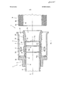
На фиг. 1 показана в продольном разрезе система 1 согласно первому варианту осуществления изобретения, имеющая фитинг 2 согласно первому варианту осуществления изобретения и наружную муфту 4. Фитинг 2 содержит внешний трубчатый корпус 6 фитинга, имеющий внешнюю опорную часть 8 и основную часть 10. Кроме того, фитинг 2 содержит внутренний трубчатый корпус 12 фитинга, имеющий внутреннюю опорную часть 14 и основную часть 16. В данном случае внешний корпус 6 фитинга выполнен полностью из полифенилсульфона, хотя могут быть применены и другие пластмассы. Внутренний корпус 12 фитинга в данном случае выполнен полностью из меди, хотя могут быть применены и другие металлы.In FIG. 1 is a longitudinal sectional view of a system 1 according to a first embodiment of the invention, having a fitting 2 according to a first embodiment of the invention and an
Корпусы 6, 12 фитинга могут быть вставлены в трубчатый конец своими концами 6а, 12а, обращенными по направлению к трубчатому концу 18. В этом случае, в отличие от основных частей 10, 16, только опорные части 8, 14 могут быть вставлены в трубчатый конец 18. Трубчатый конец в данном примере представляет собой конец многослойной композитной трубы, имеющей три слоя 18а, 18b, 18с. В частности, внутренний слой 18с выполнен из сшитого полиэтилена (РЕ-Ха, ΡΕ-Xb, РЕ-Хс), средний слой 18b выполнен из алюминия, и внешний слой 18а выполнен из обычного полиэтилена (РЕ) и выполняет функцию защитного слоя.The
Внутренний корпус 12 фитинга расположен в целом соосно и внутри внешнего корпуса 6 фитинга, так что внутренняя опорная часть 14 также расположена в целом соосно и внутри внешнего корпуса 6 фитинга по общей продольной оси А. Внутренний корпус 12 фитинга в этом случае вставлен частично с превышением размера во внешний корпус 6 фитинга. В частности, в областях 24а и 24b, это приводит к локальному соединению с тугой посадкой в виде посадки с натягом между внутренней окружной поверхностью 20 внешней опорной части 6 и внешней окружной поверхностью 22 внутренней опорной части 12. В результате внутренняя окружная поверхность 20 внешней опорной части 6 и внешняя окружная поверхность 22 внутренней опорной части 12 уплотнены относительно друг друга в областях, в данном случае - в областях 24а и 24b.The
Между уплотненными таким образом областями 24а и 24b между внутренним и внешним корпусами 6, 12 фитинга образована полость 28а, расположенная между внутренней окружной поверхностью 20 внешней опорной части 6 и внешней окружной поверхностью 22 внутренней опорной части 12. Полость 28а, которая в этом случае имеет кольцевую окружную форму, образована посредством аналогичного кольцевого окружного углубления во внутренней окружной поверхности 20 внешней опорной части 8. Полость 28а заполнена воздухом и имеет продольную протяженность в продольном осевом направлении. Поскольку области 24а и 24b уплотнены, расположенная между ними полость 28а изолирована от окружающей среды и от пространства внутри трубопровода.Between the
В области полости 28а на внешней окружной поверхности 30 внешней опорной части 8 выполнен радиально направленный наружу выступ в виде зубчиков 32а. Зубчики 32а выполнены в виде заусенцев, что предотвращает соскальзывание трубчатого конца 18. Эти зубчики обеспечивают эффективное уплотнение с внутренней окружной поверхностью вставляемого трубчатого конца 18. Благодаря тому, что радиально направленный наружу выступ 32а выполнен в области полости 28а, внешняя опорная часть 8 в данной области может прогибаться внутрь полости 28а. В результате воздействия сжимающих и изгибающих усилий зубчики 32 могут быть уплотнены относительно трубчатого конца 18 после того, как трубчатый конец перемещен на внешнюю опорную часть 8 и на зубчики 32а. Внешняя опорная часть 8 может также участвовать в возможной упругости трубчатого конца 18 благодаря полости 28а.In the region of the
На внешней окружной поверхности 30 внешней опорной части 8 выполнен дополнительный радиально направленный наружу выступ в виде зубчиков 32b в области конца 6а корпуса 6 фитинга, обращенного в сторону трубчатого конца 18. Форма зубчиков 32b аналогична форме зубчиков 32а, хотя могут быть выбраны и другие конструкции. Поскольку конец 6а внешней опорной части 8, обращенный по направлению к трубчатому концу 18, в осевом направлении проходит дальше конца 12а внутренней опорной части 14, обращенного по направлению к трубчатому концу 18, внешняя опорная часть 8 и внутренняя опорная часть 14 не перекрываются в радиальном направлении, так что в области расположения дополнительных зубчиков 32b на конце 6а внешней опорной части 8, обращенном по направлению к трубчатому концу 18, образована область, которая может свободно прогибаться внутрь. В этой области уплотнение внешней опорной части 8 относительно трубчатого конца 18 может происходить так, как оно происходило бы в случае фитинга, выполненного полностью из пластмассы. Толщина стенки внешней опорной части 8 в этой области, по меньшей мере, частично увеличена по сравнению с толщиной стенки остальной части внешней опорной части 8. Таким образом, на внутренней окружной поверхности внешней опорной части образован упор 34 в осевом направлении для внутреннего корпуса 12 фитинга.On the outer
Внешний корпус 6 фитинга содержит фланец 36, выступающий наружу в радиальном направлении от основной части 10. Этот фланец используют в качестве упора в осевом направлении для наружной муфты 4. Кроме того, фланец 36 может обеспечивать легкость в обращении при монтаже, в частности при перемещении трубчатого конца 18.The
Наружная муфта 4 в целом выполнена цилиндрической и соосной с корпусами 6, 12 фитинга или с осью А. Согласно этому варианту осуществления изобретения наружная муфта выполнена из металла, хотя, в качестве альтернативы, могут быть использованы и другие материалы, в частности пластмасса. Между внутренней окружной поверхностью 38 наружной муфты 4 и внешней окружной поверхностью 30 внешней опорной части 6 образована кольцевая окружная полость 40. Для создания герметичного соединения трубчатый конец 18 вставляют в полость 40. Для облегчения вставки трубчатого конца 18 конец наружной муфты 4, обращенный в сторону трубчатого конца 18, выполнен радиально загнутым наружу. И, наоборот, обращенный от трубчатого конца 18 конец наружной муфты выполнен радиально загнутым внутрь для образования поверхности контакта с фланцем 36. Кроме того, в наружной муфте 4 выполнены отверстия 42 для контроля положения трубчатого конца 18. Наружная муфта 4 предназначена для создания направленной радиально внутрь силы, действующей на трубчатый конец 18 в области внутренней или внешней опорных частей 8, 14 во вставленном состоянии.The
Конец внутреннего корпуса 12 фитинга, обращенный в сторону от трубчатого конца 18, выходит за конец внешнего корпуса 6 фитинга, обращенный в сторону от трубчатого конца 18, в осевом направлении. В этом случае основная часть 16, примыкающая к внутренней опорной части 14 внутреннего корпуса 12 фитинга, может быть в целом цилиндрической. Тем не менее конец внутреннего корпуса 12 фитинга, обращенный в сторону от трубчатого конца 18, может иметь любую требуемую форму. В частности, форма внутреннего корпуса 12 фитинга может быть выполнена такой, чтобы к ней можно было подсоединять какие-либо другие элементы, например корпусы фитинга или фитинги.The end of the
Как показано на фиг. 1, для создания герметичного соединения трубчатого конца многослойной композитной трубы, содержащей сшитый полиэтилен, не требуются какие-либо уплотнительные кольца. Но, несмотря на это, трубчатый конец 18 может быть перемещен на фитинг 2, содержащий внутренний корпус 12 фитинга, выполненный из металла, без расширения, а в областях расположения зубчиков 32а и 32b могут быть образованы герметичные соединения. Таким образом, фитинг может быть использован, в частности, в газовых трубопроводах и трубопроводах для технической или питьевой воды.As shown in FIG. 1, no o-rings are required to create a tight joint for the tubular end of the multilayer composite pipe containing cross-linked polyethylene. But, despite this, the
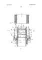
На фиг. 2 представлена система 1 согласно второму варианту осуществления изобретения, имеющая фитинг 2 согласно второму варианту осуществления изобретения и наружную муфту 4, в сочетании с дополнительной системой 1′ фитинга, в продольном разрезе.In FIG. 2 shows a system 1 according to a second embodiment of the invention, having a fitting 2 according to a second embodiment of the invention and an
Поскольку система 1, показанная на фиг. 2, аналогична системе 1, показанной на фиг. 1, соответствующие элементы системы 1 согласно второму варианту осуществления обозначены такими же ссылочными обозначениями.Since the system 1 shown in FIG. 2 is similar to system 1 shown in FIG. 1, corresponding elements of the system 1 according to the second embodiment are denoted by the same reference signs.
Кроме того, фиг. 2 иллюстрирует способ, посредством которого фитинг 2 может соединяться с левой стороны с дополнительной системой 1′ фитинга, конструкция которой отличается от раскрытой согласно изобретению. Ее конструкция, вероятно, аналогична конструкции системы 1. В этом случае соответствующие элементы системы указываются ссылочными обозначениями со штрихом.In addition, FIG. 2 illustrates a method by which a
В отличие от показанного на фиг. 1 фитинга 2, фитинг 2, показанный на фиг. 2, содержит внутреннюю опорную часть 14, проходящую дальше в осевом направлении. Таким образом, внутренняя опорная часть 14 и внешняя опорная часть 8 все еще перекрываются в области дополнительного радиально направленного наружу выступа в виде зубчиков 32b. Для обеспечения аналогичной гибкости в области зубчиков 32b по сравнению с областью, свободно прогибающейся внутрь, на конце 6а внешней опорной части 8, обращенной в сторону трубчатого конца 18, как показано на фиг. 1, в области зубчиков 32b выполнена дополнительная полость 28b, аналогичная полости 28а в области расположения зубчиков 32а. В отличие от фитинга, показанного на фиг. 1, полости 28а, 28b выполнены посредством обеспечения углублений на внешней окружной поверхности 22 внутренней опорной части 14. Согласно этому варианту осуществления, однако, конец 6а внешней опорной части 8, обращенный в сторону трубчатого конца 18, выходит за конец 12а внутренней опорной части 14, обращенный в сторону трубчатого конца 18, в осевом направлении. В результате обеспечиваются три области 24а, 24b, 24с, в которых посредством посадки с натягом внешняя опорная часть 8 уплотнена относительно внутренней опорной части 14. Полости 28а, 28b расположены между областями 24а, 24b, 24с. Однако они могут быть расположены и в других местах. В частности, может быть выбрано другое количество полостей 28а, 28b и областей 24а, 24b, 24с.In contrast to that shown in FIG. 1 of
Еще одно отличие заключается в том, что фланец 36 выполнен в виде элемента, отдельного от основной части 10 внешнего корпуса фитинга. Фланец 36 выполнен из того же материала, что и внешний корпус 6 фитинга, хотя другие материалы также могут быть использованы. Фланец 36 снабжен выступом-защелкой 44, а основная часть 10 имеет соответствующий паз 46 защелки на внешней окружной поверхности, которые предназначены для фиксации фланца 36 в осевом направлении относительно внешнего корпуса 6 фитинга. Кроме того, во фланце 36 выполнено углубление 48, предназначенное для приема конца наружной муфты 4, обращенного в сторону от трубчатого конца 18.Another difference is that the
В отличие от наружной муфты, показанной на фиг. 1, наружная муфта 4, показанная на фиг. 2, содержит фиксирующий выступ 50, предназначенный для фиксации трубчатого конца 18. Разумеется, в конструкции может быть выполнено множество таких фиксирующих выступов.Unlike the outer sleeve shown in FIG. 1, the
За основной частью 16 внутреннего корпуса 12 фитинга расположена, как показано на левой стороне фиг. 2, дополнительная внутренняя основная часть 16′ внутреннего корпуса 12 фитинга. Поперечное сечение внутренней основной части 16′ внутреннего корпуса 12 фитинга уменьшено в двух местах таким образом, чтобы можно было соединить внешний корпус 6′ фитинга с наружной муфтой 4′, диаметр которой меньше диаметра корпуса 6 фитинга и наружной муфты 4. Таким образом, трубчатый конец меньшего поперечного сечения может быть подсоединен с левой стороны. Возможна также симметричная конструкция такая, что система 1′ фитинга также может быть выполнена согласно изобретению.Behind the
В рассматриваемом случае, однако, хотя конструкция системы 1′ аналогична конструкции системы 1, показанной на фиг. 1 или фиг. 2, выполнена только одна внешняя опорная часть 8′. Внешняя опорная часть 8′ не перекрывается в радиальном направлении с внутренней опорной частью. Внутренняя опорная часть 8′ может быть выполнена целиком из пластмассы. Соответственно, толщину стенки внутренней опорной части 8′ также выбирают больше толщины стенки опорной части 8. Герметичное соединение между основной частью 16′ и основной частью 10′ внешнего корпуса 6′ фитинга, как и ранее, обеспечивается посадкой с натягом.In this case, however, although the design of system 1 ′ is similar to that of system 1 shown in FIG. 1 or FIG. 2, only one
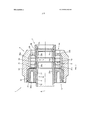
На фиг. 3 показана система 1 согласно третьему варианту осуществления изобретения, имеющая фитинг 2 согласно третьему варианту осуществления изобретения и наружную муфту 4, в продольном разрезе. Трубчатый конец 18 не показан. Фитинг 2 очень похож на фитинг, показанный на фиг. 2. Однако в фитинге, показанном на фиг. 3, фланец 36 основной части 10 внешней опорной части 6 отличается от фланца, показанного на фиг. 2. Фланец 38 содержит средство 52 для присоединения к наружной муфте 4, которое согласно этому варианту осуществления выполнено из двух частей и включает в себя соединительную муфту 4а и прижимной корпус 4b. В рассматриваемом примере соединительная муфта 4а и фланец соединены посредством винтовой резьбы 52. Винтовая резьба 52 вырезана вместе с выемкой 36а на фланце 36. При навинчивании соединительной муфты 4а на винтовую резьбу 52 фланца прижимной корпус 4b прижимается в целом радиально внутрь к внешней окружной поверхности трубчатого конца 18, вставленного в кольцевую окружную полость 40, благодаря тому, что внутренняя окружная поверхность 38а соединительной муфты 4а выполнена со скосом относительно осевого направления А и внешняя окружная поверхность прижимного корпуса 4b соответствует ей. На внутренней окружной поверхности 38b прижимного корпуса 4b в этом случае выполнены фиксирующие выступы 50.In FIG. 3 shows a system 1 according to a third embodiment of the invention, having a fitting 2 according to a third embodiment of the invention and an
Таким образом, трубчатый конец 18, вставленный в полость 40, не может выскользнуть из фитинга 2 и прижат к внешней окружной поверхности 30 внешней опорной части или к радиально направленным наружу выступам 32а, 32b, которые выполнены для создания особо надежного и герметичного соединения.Thus, the
Claims (13)
Applications Claiming Priority (3)
| Application Number | Priority Date | Filing Date | Title |
|---|---|---|---|
| DE102012108146.8 | 2012-09-03 | ||
| DE102012108146.8A DE102012108146B4 (en) | 2012-09-03 | 2012-09-03 | Fitting, system with such a fitting and tight connection with such a fitting |
| PCT/EP2013/066401 WO2014032911A1 (en) | 2012-09-03 | 2013-08-05 | Fitting, system comprising such a fitting, and sealed connection with such a fitting |
Publications (1)
| Publication Number | Publication Date |
|---|---|
| RU2589974C1 true RU2589974C1 (en) | 2016-07-10 |
Family
ID=47357927
Family Applications (1)
| Application Number | Title | Priority Date | Filing Date |
|---|---|---|---|
| RU2015112143/06A RU2589974C1 (en) | 2012-09-03 | 2013-08-05 | Fitting, system containing such fitting, and airtight connection with such fitting |
Country Status (14)
| Country | Link |
|---|---|
| EP (2) | EP2703707B1 (en) |
| AU (1) | AU2013307584B2 (en) |
| BR (1) | BR112015004610B1 (en) |
| DE (1) | DE102012108146B4 (en) |
| DK (1) | DK2703707T3 (en) |
| ES (1) | ES2604013T3 (en) |
| HR (1) | HRP20161554T1 (en) |
| HU (1) | HUE032239T2 (en) |
| LT (1) | LT2893241T (en) |
| MX (1) | MX356018B (en) |
| PL (1) | PL2893241T3 (en) |
| RU (1) | RU2589974C1 (en) |
| SI (1) | SI2893241T1 (en) |
| WO (1) | WO2014032911A1 (en) |
Cited By (1)
| Publication number | Priority date | Publication date | Assignee | Title |
|---|---|---|---|---|
| RU2766955C1 (en) * | 2018-06-08 | 2022-03-16 | Виега Текнолоджи Гмбх Энд Ко.Кг | Fitting for connection to at least one pipe |
Families Citing this family (9)
| Publication number | Priority date | Publication date | Assignee | Title |
|---|---|---|---|---|
| GB201309330D0 (en) | 2013-05-23 | 2013-07-10 | Sev Trent Water Ltd | Pipe Connection |
| US11543065B2 (en) | 2016-09-02 | 2023-01-03 | Zurn Industries, Llc | Extruded cold-expansion compression collar |
| US11541581B2 (en) | 2016-09-02 | 2023-01-03 | Zurn Industries, Llc | Injection molded cold-expansion compression collar |
| US11054076B2 (en) | 2016-11-04 | 2021-07-06 | Zurn Industries, Llc | Reinforcing ring with sleeve |
| DE102017105505A1 (en) | 2017-03-15 | 2018-09-20 | Viega Technology Gmbh & Co. Kg | Fitting for connection to at least one pipe and method for establishing a connection |
| CN108890235B (en) * | 2018-08-22 | 2023-05-05 | 江苏众信绿色管业科技有限公司 | Steel lining stainless steel groove part and manufacturing method thereof |
| DE202019104494U1 (en) * | 2019-08-15 | 2020-11-25 | Rehau Ag + Co | Connecting element and this comprehensive pipe connection |
| DE102019216828A1 (en) * | 2019-10-31 | 2021-05-06 | Fränkische Rohrwerke Gebr. Kirchner Gmbh & Co. Kg | PRESS FITTING |
| ES1281185Y (en) * | 2021-10-07 | 2022-01-31 | Ais Rdi S L U | ACCESSORY SET FOR PIPE CONNECTION |
Citations (4)
| Publication number | Priority date | Publication date | Assignee | Title |
|---|---|---|---|---|
| US3951438A (en) * | 1973-07-06 | 1976-04-20 | Dunlop Limited | Fastening means |
| EP0848200A2 (en) * | 1996-12-13 | 1998-06-17 | Daniel Knipping | Press-fitted pipe joint |
| WO2004104466A1 (en) * | 2003-05-22 | 2004-12-02 | Yorkshire Fittings Limited | Tube coupling device |
| RU2355937C2 (en) * | 2006-09-13 | 2009-05-20 | Евгений Дмитриевич Самохвалов | Solid end reinforcement of high pressure hose |
Family Cites Families (12)
| Publication number | Priority date | Publication date | Assignee | Title |
|---|---|---|---|---|
| US3614137A (en) | 1970-04-09 | 1971-10-19 | Perfection Corp | Reinforced plastic fitting |
| DE8712048U1 (en) | 1987-09-05 | 1988-12-29 | Robert Bosch Gmbh, 7000 Stuttgart | Gas and liquid tight connection |
| DE3808383A1 (en) * | 1988-03-12 | 1989-09-28 | Witzenmann Metallschlauchfab | LINE CONNECTION |
| DE19607630C1 (en) | 1996-02-29 | 1997-07-31 | Hewing Gmbh | Press fitting for connecting a pipe |
| ATE302391T1 (en) | 1999-01-25 | 2005-09-15 | Jrg Gunzenhauser Ag | SCREW-ON PIPE CONNECTION |
| ES2267971T3 (en) | 2002-05-31 | 2007-03-16 | Ke-Kelit Kunststoffwerk Gesellschaft M.B.H. | PROFILE PIECE TO GUIDE A FLUID, ESPECIALLY FOR WATER CONDUCT FACILITIES. |
| DE20307994U1 (en) | 2003-05-22 | 2003-09-25 | Kretz, Gerd, 74915 Waibstadt | Connector fitting for pipes, contains sleeve made from material resistant to corrosion and mechanical stress |
| US7806442B2 (en) * | 2006-03-03 | 2010-10-05 | Parker-Hannifin Corporation | Hose coupling with molded seal insert |
| DE102006051774A1 (en) | 2006-11-03 | 2008-05-08 | Uponor Innovation Ab | Fitting for a pipe |
| DE102007042605A1 (en) * | 2007-09-07 | 2009-03-12 | Witzenmann Gmbh | Connecting device for a ring-corrugated or helically corrugated metal hose or bellows, and method and arrangement for producing such |
| DE102007053518A1 (en) | 2007-11-09 | 2009-05-20 | Tece Gmbh | Pipe connector for use as clamping, pressing or connecting assembly, has hollow cylindrical support body, which has nominal diameter, and is formed at front end for fitting of pipe |
| DE202008008554U1 (en) | 2008-06-30 | 2009-11-19 | Rehau Ag + Co | Plastic sliding sleeve and connection fitting with such a sliding sleeve |
-
2012
- 2012-09-03 DE DE102012108146.8A patent/DE102012108146B4/en active Active
- 2012-11-26 EP EP12194193.4A patent/EP2703707B1/en active Active
- 2012-11-26 DK DK12194193.4T patent/DK2703707T3/en active
-
2013
- 2013-08-05 BR BR112015004610-0A patent/BR112015004610B1/en not_active IP Right Cessation
- 2013-08-05 EP EP13745416.1A patent/EP2893241B1/en active Active
- 2013-08-05 SI SI201330386A patent/SI2893241T1/en unknown
- 2013-08-05 AU AU2013307584A patent/AU2013307584B2/en active Active
- 2013-08-05 RU RU2015112143/06A patent/RU2589974C1/en active
- 2013-08-05 ES ES13745416.1T patent/ES2604013T3/en active Active
- 2013-08-05 LT LTEP13745416.1T patent/LT2893241T/en unknown
- 2013-08-05 MX MX2015002733A patent/MX356018B/en active IP Right Grant
- 2013-08-05 PL PL13745416T patent/PL2893241T3/en unknown
- 2013-08-05 WO PCT/EP2013/066401 patent/WO2014032911A1/en active Application Filing
- 2013-08-05 HU HUE13745416A patent/HUE032239T2/en unknown
-
2016
- 2016-11-22 HR HRP20161554TT patent/HRP20161554T1/en unknown
Patent Citations (4)
| Publication number | Priority date | Publication date | Assignee | Title |
|---|---|---|---|---|
| US3951438A (en) * | 1973-07-06 | 1976-04-20 | Dunlop Limited | Fastening means |
| EP0848200A2 (en) * | 1996-12-13 | 1998-06-17 | Daniel Knipping | Press-fitted pipe joint |
| WO2004104466A1 (en) * | 2003-05-22 | 2004-12-02 | Yorkshire Fittings Limited | Tube coupling device |
| RU2355937C2 (en) * | 2006-09-13 | 2009-05-20 | Евгений Дмитриевич Самохвалов | Solid end reinforcement of high pressure hose |
Cited By (1)
| Publication number | Priority date | Publication date | Assignee | Title |
|---|---|---|---|---|
| RU2766955C1 (en) * | 2018-06-08 | 2022-03-16 | Виега Текнолоджи Гмбх Энд Ко.Кг | Fitting for connection to at least one pipe |
Also Published As
| Publication number | Publication date |
|---|---|
| AU2013307584A1 (en) | 2015-03-12 |
| WO2014032911A1 (en) | 2014-03-06 |
| DE102012108146A1 (en) | 2014-03-06 |
| EP2703707A1 (en) | 2014-03-05 |
| SI2893241T1 (en) | 2016-12-30 |
| EP2893241A1 (en) | 2015-07-15 |
| ES2604013T3 (en) | 2017-03-02 |
| HRP20161554T1 (en) | 2016-12-30 |
| DE102012108146B4 (en) | 2022-05-25 |
| DK2703707T3 (en) | 2017-12-11 |
| PL2893241T3 (en) | 2017-02-28 |
| BR112015004610B1 (en) | 2020-09-29 |
| EP2703707B1 (en) | 2017-10-25 |
| LT2893241T (en) | 2016-11-25 |
| MX356018B (en) | 2018-05-09 |
| MX2015002733A (en) | 2015-05-15 |
| EP2893241B1 (en) | 2016-10-19 |
| AU2013307584B2 (en) | 2016-06-16 |
| HUE032239T2 (en) | 2017-09-28 |
| BR112015004610A2 (en) | 2017-07-04 |
Similar Documents
| Publication | Publication Date | Title |
|---|---|---|
| RU2589974C1 (en) | Fitting, system containing such fitting, and airtight connection with such fitting | |
| GB2503880A (en) | Insert for Pipes | |
| RU2484353C1 (en) | Polymer tube joint assembly | |
| JP2020024045A (en) | Pipe joint | |
| JP2004092699A (en) | Flexible pipe joint | |
| JP5269178B2 (en) | How to assemble pipe fittings | |
| CN103562611A (en) | Pipe fitting element for connecting a polypropylene pipe and a metal pipe | |
| RU2498146C2 (en) | Fitting for tight joint at pipe end, system with fitting (versions), fitting use (versions) | |
| JP2018017293A (en) | Pressure-proof pipe joint and pressure-proof pipe joint structure | |
| CN216643433U (en) | Pipe joint without O-shaped ring | |
| BR122018015577B1 (en) | PROTECTIVE RING FOR USE IN A COUPLING ASSEMBLY AND METHOD FOR COUPLING TWO TUBULARS | |
| JP2015078749A (en) | Pipe joint | |
| JP2002323179A (en) | Pipe joint | |
| JP5812410B2 (en) | Pipe fitting tool and pipe connection structure | |
| JP2008064169A (en) | Pipe joint | |
| RU148621U1 (en) | PIPE AND FITTING JOINT ASSEMBLY PERFORMED FROM POLYMERIC MATERIALS | |
| RU2557142C1 (en) | Method of connection of fitting and pipe made out of polymer materials and connection assembly | |
| JP5967271B2 (en) | Fitting and fitting mounting structure | |
| GB2505420A (en) | Pipe insert | |
| JP2011106539A (en) | Collet for holding pipe | |
| JP6894276B2 (en) | Piping structure construction method and piping structure | |
| ITBS20030054U1 (en) | JUNCTION JOINT FOR MULTILAYER PIPES | |
| JP2014051999A (en) | Double-layered pipe | |
| JP3206965U (en) | Gasket and pipe joint provided with the same | |
| JP6150165B2 (en) | Pipe with telescopic joint and method for manufacturing pipe with telescopic joint |
Legal Events
| Date | Code | Title | Description |
|---|---|---|---|
| PD4A | Correction of name of patent owner | ||
| PC41 | Official registration of the transfer of exclusive right |
Effective date: 20170814 |