JP5812410B2 - Pipe fitting tool and pipe connection structure - Google Patents
Pipe fitting tool and pipe connection structure Download PDFInfo
- Publication number
- JP5812410B2 JP5812410B2 JP2011236724A JP2011236724A JP5812410B2 JP 5812410 B2 JP5812410 B2 JP 5812410B2 JP 2011236724 A JP2011236724 A JP 2011236724A JP 2011236724 A JP2011236724 A JP 2011236724A JP 5812410 B2 JP5812410 B2 JP 5812410B2
- Authority
- JP
- Japan
- Prior art keywords
- pipe
- diameter portion
- outer diameter
- sleeve
- annular seal
- Prior art date
- Legal status (The legal status is an assumption and is not a legal conclusion. Google has not performed a legal analysis and makes no representation as to the accuracy of the status listed.)
- Expired - Fee Related
Links
Images


Description
本発明は、パイプとその接続相手とを接続するためのパイプ継手用具及びパイプ接続構造に関する。 The present invention relates to a pipe joint tool and a pipe connection structure for connecting a pipe and its connection partner.
従来のパイプ接続構造として、接続相手に備えた第1のフランジとパイプ側に備えた第2のフランジとをクイックファスナーによって接合状態に保持可能としたものが知られている(例えば、特許文献1参照)。 As a conventional pipe connection structure, a structure in which a first flange provided on a connection partner and a second flange provided on a pipe side can be held in a joined state by a quick fastener is known (for example, Patent Document 1). reference).
ところが、上述した従来のパイプ接続構造では、パイプの先端寄り外周面を全周に亘って溝状に削り取ることで第2のフランジが形成されていた為、パイプの強度が著しく低下するという問題があった。 However, in the conventional pipe connection structure described above, since the second flange is formed by scraping the outer peripheral surface near the tip of the pipe into a groove shape over the entire circumference, there is a problem in that the strength of the pipe is significantly reduced. there were.
本発明は、上記事情に鑑みてなされたものであって、クイックファスナーによってパイプの接続相手に備えられた第1のフランジと接合状態に保持可能な第2のフランジを、パイプの強度低下を抑えながらパイプに設けることが可能なパイプ継手用具及びパイプ接続構造の提供を目的とする。 This invention is made in view of the said situation, Comprising: The 2nd flange which can be hold | maintained in a joining state with the 1st flange with which the connection partner of the pipe was equipped with quick fastener suppresses the strength reduction of a pipe. An object of the present invention is to provide a pipe joint tool and a pipe connection structure that can be provided on a pipe.
上記目的を達成するためになされた請求項1の発明に係るパイプ継手用具は、パイプの先端部を拡径変形させてなるパイプ先端大径部の内側に嵌合可能な雄スリーブと、パイプのパイプ先端大径部側の接続相手に基端部を固定され、先端側から内側に雄スリーブと共にパイプ先端大径部を嵌合可能な雌スリーブと、パイプの外側に挿通されてパイプ先端大径部の基端側の段差部に係止可能な係止リングと、雌スリーブ及び係止リングの両方に設けられ、パイプ先端大径部及び雄スリーブを雌スリーブの内部に嵌合した場合に互いに接合されかつクイックファスナーによって接合状態に保持可能な第1及び第2のフランジとを備え、雄スリーブには、パイプ先端大径部の内径より大きな外径を有しかつパイプ先端大径部の先端から外側に突出する大外径部と、大外径部の外周面に形成された第1の環状シール溝と、第1の環状シール溝に収容されて雌スリーブの内周面に密着する第1の環状シール部材と、パイプ先端大径部の内径より小さい外径を有しかつパイプ先端大径部の内側に嵌合される小外径部と、小外径部の外周面に形成された第2の環状シール溝と、第2の環状シール溝に収容されてパイプ先端大径部の内周面に密着する第2の環状シール部材とが備えられたところに特徴を有する。 In order to achieve the above object, a pipe joint device according to the invention of claim 1 includes a male sleeve that can be fitted inside a pipe tip large-diameter portion formed by expanding and deforming the tip portion of the pipe, The base end is fixed to the connection partner on the pipe tip large diameter side, the female sleeve that can fit the pipe tip large diameter part together with the male sleeve from the tip side to the inside, and the pipe tip large diameter inserted through the outside of the pipe The locking ring that can be locked to the stepped portion on the base end side of the portion, the female sleeve, and the locking ring are provided on both the female sleeve and the locking ring. The first and second flanges are joined and can be held in a joined state by a quick fastener, and the male sleeve has an outer diameter larger than the inner diameter of the pipe tip large-diameter portion and the tip of the pipe tip large-diameter portion. Protrude outward from A large outer diameter portion, a first annular seal groove formed on the outer peripheral surface of the large outer diameter portion, and a first annular seal member that is housed in the first annular seal groove and is in close contact with the inner peripheral surface of the female sleeve A small outer diameter portion having an outer diameter smaller than the inner diameter of the pipe tip large diameter portion and fitted inside the pipe tip large diameter portion, and a second annular formed on the outer peripheral surface of the small outer diameter portion It is characterized in that a seal groove and a second annular seal member that is housed in the second annular seal groove and is in close contact with the inner peripheral surface of the pipe tip large-diameter portion are provided.
請求項2の発明は、請求項1に記載のパイプ継手用具において、雄スリーブの外周面のうち小外径部と大外径部との間には、大外径部より小径かつパイプ先端大径部の内径よりも大径な中外径部が設けられたところに特徴を有する。 According to a second aspect of the present invention, in the pipe joint tool according to the first aspect, between the small outer diameter portion and the large outer diameter portion of the outer peripheral surface of the male sleeve, the diameter of the pipe is larger than that of the large outer diameter portion. It is characterized in that a medium-outer diameter portion larger than the inner diameter of the diameter portion is provided.
請求項3の発明は、請求項1又は2に記載のパイプ継手用具において、雌スリーブの内面に形成され、雄スリーブの先端面と対向する内側段差面を備えたところに特徴を有する。 The invention of claim 3 is characterized in that, in the pipe joint tool according to claim 1 or 2 , an inner step surface formed on the inner surface of the female sleeve and facing the front end surface of the male sleeve is provided.
請求項4の発明に係るパイプ継手用具は、パイプの先端を拡径変形させてなるパイプ先端大径部の内側に嵌合された状態で、そのパイプのパイプ先端大径部側の接続相手に基端部を固定されている雌スリーブの内側に挿入可能な雄スリーブと、パイプの外側に挿通されてパイプ先端大径部の基端側の段差部に係止可能な係止リングと、係止リングに設けられ、雌スリーブの側方に張り出した第1のフランジに接合された状態にクイックファスナーにて保持可能な第2のフランジとを備え、雄スリーブには、パイプ先端大径部の内径より大きな外径を有しかつパイプ先端大径部の先端から外側に突出する大外径部と、大外径部の外周面に形成された第1の環状シール溝と、第1の環状シール溝に収容されて雌スリーブの内周面に密着する第1の環状シール部材と、パイプ先端大径部の内径より小さい外径を有しかつパイプ先端大径部の内側に嵌合される小外径部と、小外径部の外周面に形成された第2の環状シール溝と、第2の環状シール溝に収容されてパイプ先端大径部の内周面に密着する第2の環状シール部材とが備えられたところに特徴を有する。 The pipe joint tool according to the invention of claim 4 is connected to the pipe on the pipe tip large-diameter portion side in a state of being fitted inside the pipe tip large-diameter portion obtained by expanding and deforming the tip of the pipe. A male sleeve that can be inserted into the inside of the female sleeve to which the base end portion is fixed, a locking ring that is inserted through the outside of the pipe and can be locked to a step portion on the base end side of the large diameter portion of the pipe tip, And a second flange that can be held by a quick fastener in a state of being joined to a first flange that protrudes to the side of the female sleeve . A large outer diameter portion having an outer diameter larger than the inner diameter and projecting outward from the distal end of the pipe distal end large diameter portion, a first annular seal groove formed on an outer peripheral surface of the large outer diameter portion, and a first annular shape A first that is received in the seal groove and closely contacts the inner peripheral surface of the female sleeve And a small outer diameter portion having an outer diameter smaller than the inner diameter of the pipe tip large-diameter portion and fitted inside the pipe tip large-diameter portion, and a first formed on the outer peripheral surface of the small outer-diameter portion. The second annular seal groove and the second annular seal member that is accommodated in the second annular seal groove and is in close contact with the inner peripheral surface of the pipe tip large-diameter portion are characterized.
請求項5の発明に係るパイプ接続構造は、クイックファスナーを利用してパイプを接続相手に接続するパイプ接続構造において、第1のフランジを外面に備えた雌スリーブを接続相手に固定する一方、第2のフランジを外面に備えた係止リングをパイプの外面に挿通し、パイプの先端部を拡径変形させてパイプ先端大径部を形成すると共に、そのパイプ先端大径部の基端側の段差部に係止リングを係止して抜け止めし、さらに、パイプ先端大径部の内側に嵌合した雄スリーブを設け、雄スリーブと共にパイプ先端大径部を雌スリーブの内側に嵌合して第1と第2のフランジを接合し、クイックファスナーにて第1と第2のフランジを接合状態に保持し、雄スリーブに、パイプ先端大径部の内径より大きな外径を有しかつパイプ先端大径部の先端から外側に突出する大外径部と、大外径部の外周面に形成された第1の環状シール溝と、第1の環状シール溝に収容されて雌スリーブの内周面に密着する第1の環状シール部材と、パイプ先端大径部の内径より小さい外径を有しかつパイプ先端大径部の内側に嵌合される小外径部と、小外径部の外周面に形成された第2の環状シール溝と、第2の環状シール溝に収容されてパイプ先端大径部の内周面に密着する第2の環状シール部材とを備えたところに特徴を有する。
請求項6の発明は、請求項5に記載のパイプ接続構造において、雄スリーブの外周面のうち小外径部と大外径部との間には、大外径部より小径かつパイプ先端大径部の内径よりも大径な中外径部が設けられたところに特徴を有する。
請求項7の発明は、請求項5又は6に記載のパイプ接続構造において、雌スリーブの内面に形成され、雄スリーブの先端面と対向する内側段差面を備えたところに特徴を有する。
According to a fifth aspect of the present invention, there is provided a pipe connection structure in which a pipe is connected to a connection partner using a quick fastener, and a female sleeve having a first flange on the outer surface is fixed to the connection partner, A locking ring having an outer surface of the flange 2 is inserted into the outer surface of the pipe, and the distal end portion of the pipe is expanded and deformed to form a large diameter portion at the distal end of the pipe. A locking ring is locked to the stepped portion to prevent it from coming off, and a male sleeve fitted inside the pipe tip large diameter part is provided, and the pipe tip large diameter part is fitted inside the female sleeve together with the male sleeve. The first and second flanges are joined together, the first and second flanges are held in a joined state by a quick fastener , the male sleeve has an outer diameter larger than the inner diameter of the pipe tip large diameter portion, and the pipe Tip of tip large diameter part A large outer diameter portion protruding outward from the first outer circumferential portion, a first annular seal groove formed on the outer peripheral surface of the large outer diameter portion, and a first annular seal groove that is received in the first annular seal groove and closely contacts the inner peripheral surface of the female sleeve. 1 is formed on the outer peripheral surface of the small outer diameter portion, the small outer diameter portion having an outer diameter smaller than the inner diameter of the pipe tip large diameter portion and fitted inside the pipe tip large diameter portion. The second annular seal groove and the second annular seal member that is accommodated in the second annular seal groove and is in close contact with the inner peripheral surface of the pipe tip large-diameter portion are characterized.
According to a sixth aspect of the present invention, in the pipe connection structure according to the fifth aspect, between the small outer diameter portion and the large outer diameter portion of the outer peripheral surface of the male sleeve, the diameter of the pipe is larger than that of the large outer diameter portion. It is characterized in that a medium-outer diameter portion larger than the inner diameter of the diameter portion is provided.
The invention of claim 7 is characterized in that, in the pipe connection structure according to claim 5 or 6, an inner step surface is provided on the inner surface of the female sleeve and faces the front end surface of the male sleeve.
[請求項1,4及び5発明]
請求項1,4及び5の発明によれば、パイプの接続相手に固定される雌スリーブに第1のフランジが設けられる一方、クイックファスナーにより第1のフランジと接合状態に保持される第2のフランジがパイプの外側に挿通された係止リングに設けられ、その係止リングは、パイプの先端部を拡径変形させてなるパイプ先端大径部の基端側の段差部に係止することでパイプに対して位置決めされる。そして、パイプ先端大径部とその内側に嵌合された雄スリーブとを共に雌スリーブの内側に挿入し、雌スリーブに備えた第1のフランジと係止リングに備えた第2のフランジとを接合して、これらをクイックファスナーで接合状態に保持することで、パイプが雌スリーブに対して抜け止めされ、パイプとその接続相手とを接続状態に保持することができる。このように、本発明によれば、クイックファスナーによって接続相手側(雌スリーブ)の第1のフランジと接合状態に保持される第2のフランジを、パイプの外周面を削り取ることなくパイプ側に設けることができるから、パイプの強度低下を従来よりも抑えることができる。また、パイプの先端部を拡径変形させてなるパイプ先端大径部は、拡径変形させる前に比べて肉厚が若干減少するが、そのパイプ先端大径部を雄スリーブによって内側から補強すると共に、雌スリーブによって外側から補強することができる。
[Claims 1, 4 and 5 invention]
According to the first, fourth, and fifth aspects of the present invention, the first flange is provided on the female sleeve fixed to the connection partner of the pipe, while the second flange is held in the joined state with the first flange by the quick fastener. A flange is provided on a locking ring inserted into the outside of the pipe, and the locking ring is locked to a stepped portion on the proximal end side of the large diameter portion of the pipe distal end which is formed by expanding and deforming the distal end portion of the pipe. Is positioned with respect to the pipe. Then, the pipe tip large diameter portion and the male sleeve fitted inside the pipe are both inserted into the female sleeve, and a first flange provided on the female sleeve and a second flange provided on the locking ring are provided. By joining and holding them in a joined state with a quick fastener, the pipe is prevented from coming off from the female sleeve, and the pipe and its connection partner can be kept in a connected state. Thus, according to the present invention, the second flange that is held in a joined state with the first flange on the connection partner side (female sleeve) by the quick fastener is provided on the pipe side without scraping the outer peripheral surface of the pipe. Therefore, the strength reduction of the pipe can be suppressed as compared with the conventional case. Moreover, the pipe tip large diameter part formed by expanding and deforming the pipe tip part is slightly reduced in thickness compared to before the diameter expanding deformation, but the pipe tip large diameter part is reinforced from the inside by a male sleeve. At the same time, it can be reinforced from the outside by the female sleeve.
しかも、本発明によれば、雄スリーブとパイプ先端大径部との嵌合部分及び、雄スリーブと雌スリーブとの嵌合部分をそれぞれシールすることができ、流体の漏洩を確実に防止することができる。 Moreover, according to the present invention, the fitting portion between the male sleeve and the pipe tip large diameter portion and the fitting portion between the male sleeve and the female sleeve can be sealed, respectively, and fluid leakage can be reliably prevented. Can do.
[請求項2,6の発明]
請求項2,6の発明によれば、パイプの先端開口縁が中外径部に突き当たって、パイプの先端面と雄スリーブの大外径部とが離して配置される。これにより、雄スリーブが金属製でありかつ、パイプが、所謂「アルミ複合管」である場合に、パイプの先端面から露出したアルミニウム層が雄スリーブに接触することによる電気化学的腐食を防止することができる。
[Inventions of Claims 2 and 6 ]
According to the invention of claim 2, 6, the tip opening edge of the pipe abuts against the Chugai diameter, and the large outer diameter portion of the distal end surface and the male sleeve of the pipe are spaced apart. Thereby, when the male sleeve is made of metal and the pipe is a so-called “aluminum composite pipe”, the electrochemical corrosion due to the aluminum layer exposed from the tip end surface of the pipe coming into contact with the male sleeve is prevented. be able to.
[請求項3,7の発明]
請求項3,7の発明によれば、パイプとその接続相手とを接続した後で、雄スリーブが雌スリーブの奥側に移動してパイプ先端大径部から抜けるという不具合を防止することができる。
[Inventions of Claims 3 and 7 ]
According to invention of Claim 3 , 7 , after connecting a pipe and its connection partner, the malfunction that a male sleeve moves to the back | inner side of a female sleeve and falls out from a pipe tip large diameter part can be prevented. .
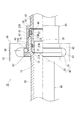
以下、本発明の一実施形態を図1〜図4に基づいて説明する。図1及び図3には、パイプ90とその接続相手F1とを接続するためのパイプ継手70が示されている。パイプ継手70は、パイプ90に組み付けられるパイプ取付具30と、パイプ90の接続相手F1に接続固定される雌スリーブ40と、それらパイプ取付具30と雌スリーブ40とを接続状態で固定するクイックファスナー60とから構成されている。また、上記したパイプ継手70のうち、パイプ取付具30及びパイプ取付具30に雌スリーブ40を加えた継手部品セット50が、本発明に係る「パイプ継手用具」に相当する(図2参照)。なお、パイプ90の接続相手F1としては、パイプや容器の他に、流体を使用したり流体を計測するための流体器具(例えば、給湯器、ガスストーブ、水道メータ、ガスメータ等)が挙げられる。
Hereinafter, an embodiment of the present invention will be described with reference to FIGS. 1 and 3 show a
パイプ継手70の構成を詳説する前に、本発明の「パイプ接続構造」に関連するパイプ90について説明しておく。本実施形態のパイプ90は、「アルミ複合管」と称される三層構造のパイプであって、中間層がアルミニウムで構成され、内外層が樹脂(例えば、架橋ポリエチレン)で構成されている。図2に示すように、パイプ90の先端部には、パイプ90を内側から拡径変形させてなる大径部91(本発明の「パイプ先端大径部」に相当する)と径徐変部92(本発明における「段差部」に相当する)とが形成され、径徐変部92より基端側が、大径部91及び径徐変部92に対して相対的に内径及び外径が小さくなった小径部93となっている。即ち、大径部91の内径及び外径は、小径部93の内径及び外径よりも大きくなっており、径徐変部92の内径及び外径は、小径部93から大径部91に向かうに従って徐々に大きくなっている。
Before describing the configuration of the
パイプ90の大径部91及び径徐変部92は、例えば以下のようにして形成される。即ち、大径部91及び径徐変部92の内面形状に対応した外面形状を有しかつ径方向外側に拡開可能な筒形のダイを、縮径状態でパイプ90の先端部内側に嵌め込み、そのダイの中心にコーン状の心金を押し込んでダイをパイプ90の内側で拡径させる。すると、ダイに押されてパイプ90の先端部が拡径変形して、大径部91と径徐変部92とが形成される。
The
パイプ継手70のうち、パイプ90の接続相手F1に固定される雌スリーブ40は、その軸方向の中間部に形成された環状段差壁42を挟んで先端側に大径筒部41を備え、環状段差壁42を挟んで基端側に小径筒部43を備えている。小径筒部43の外周面には、例えば、テーパー螺子(図1参照)が形成されており、小径筒部43を接続相手F1の接続端末に挿入して螺合することで、雌スリーブ40が接続相手F1に固定されている(図1参照)。なお、本実施形態の雌スリーブ40は金属製(詳細には、黄銅)であるが、樹脂製でもよい。
Of the
図2に示すように、雌スリーブ40の大径筒部41の内径及び外径は、それぞれ小径筒部43の内径及び外径よりも段付き状に大きくなっている。また、図3に示すように、雌スリーブ40の小径筒部43の内径はパイプ90の小径部93の内径と略同一となっている。大径筒部41の内側には、パイプ90の大径部91が挿入可能となっており、高温、高圧の流体が流れた場合の大径部91の膨張を、大径筒部41によって抑えることが可能となっている。また、大径筒部41のうち小径筒部43とは反対側の先端部には、第1のフランジ44が一体形成されている。第1のフランジ44は、大径筒部41の外周面の全周から径方向外側に張り出している。
As shown in FIG. 2, the inner diameter and the outer diameter of the large diameter
雌スリーブ40へのパイプ90の挿入を容易にするため、雌スリーブ40の先端側の開口縁46はR面取り形状になっている。また、図3に示すように、雌スリーブ40の内周面には、環状段差壁42に対応した環状の奥側段差面48と、奥側段差面48より先端側に形成された環状の中間段差面47とが形成されている。そして、雌スリーブ40の内径は、奥側段差面48より先端側が基端側より大径であり、中間段差面47より先端側が基端側より大径となっている。なお、雌スリーブ40は、金属製でもよいし樹脂製でもよい。
In order to facilitate the insertion of the
パイプ継手70のうち、パイプ90に取り付けられるパイプ取付具30は、図2に示すように、パイプ90の外側に挿通可能な金属製又は樹脂製の係止リング10と、パイプ90の大径部91の内側に嵌合可能な金属製(例えば、黄銅製)の雄スリーブ20とから構成されている。
As shown in FIG. 2, the pipe fitting 30 attached to the
係止リング10は、筒形ボディ11と筒形ボディ11の先端部の外周面全周から径方向外側に張り出した第2のフランジ12とを一体に備えている。筒形ボディ11の外径は、雌スリーブ40における大径筒部41の外径と略等しくなっている。筒形ボディ11のうち、第2のフランジ12が張り出した先端部の内周面は円錐面13となっており、その円錐面13がパイプ90の径徐変部92の外周面と当接可能となっている。また、筒形ボディ11のうち、第2のフランジ12から離れた基端側の内周面は、パイプ90の小径部93の外径と略同一径の円筒面14となっている。これにより、係止リング10はパイプ90の径徐変部92に係止可能となり、径徐変部92を通過して(乗り越えて)大径部91側へ移動することが禁止される。なお、係止リング10のパイプ90への挿入作業を容易にするために、係止リング10の基端部の開口縁15は面取り形状となっている。係止リング10は、金属製でもよいし、樹脂製でもよい。
The locking
雄スリーブ20は、パイプ90の大径部91の内側に嵌合する小外径部21と、パイプ90の大径部91の先端部から外側に突出して雌スリーブ40(詳細には、大径筒部41)の内側に嵌合する大外径部22とを有している。
The
雄スリーブ20のうち、大外径部22とは反対側の基端部外周面21Aは、先細りの円錐面となっており、その基端部外周面21Aとパイプ90における径徐変部92の内周面とが互いに当接可能となっている。また、大外径部22の外周面には、第1の環状シール溝22Mが形成されてそこに第1の環状シール部材22R(例えば、Oリング)が嵌め込まれており、小外径部21の外周面には、第2の環状シール溝21Mが形成されてそこに第2の環状シール部材21R(例えば、Oリング)が嵌め込まれている。また、雄スリーブ20の外周面のうち、小外径部21と大外径部22との間には、大外径部22よりも小径でかつ、パイプ90の大径部91の内径よりも大径な中外径部23が形成されている(図3参照)。
Out of the
図3に示すように、雄スリーブ20の内周面のうち、軸方向の中間部には、環状の中間段差面26が形成されている。そして、雄スリーブ20のうち、中間段差面26より基端側の内径は、パイプ90の小径部93における内径と略同一となっており、中間段差面26より先端側の内径は、雌スリーブ40の小径筒部43における内径と略同一になっている。このように、パイプ90及び雌スリーブ40の内側に雄スリーブ20を嵌合した状態でも流路が絞られることがないので、圧力損失を低く抑えることができる。なお、雄スリーブ20の軸方向両端部の開口縁は、共に面取り形状になっている。本実施形態の雄スリーブ20は金属製であるが、樹脂製でもよい。
As shown in FIG. 3, an annular
パイプ取付具30の係止リング10と雌スリーブ40は、クイックファスナー60によって接合状態に保持可能となっている。クイックファスナー60は、金属製の帯板状バネを左右対称に曲げ加工して形成されたものであり、図1に示すように、ヒンジ部61の両側に円弧状の挟持片62,62を備えている。挟持片62,62には、その周方向に沿って延びた挟持孔63,63が形成されており、それら挟持孔63,63の内側に、接合状態の第1のフランジ44と第2のフランジ12とを受容することで、その接合状態を保持することが可能となっている(図3参照)。
The locking
図3に示すようにクイックファスナー60によってパイプ取付具30と雌スリーブ40とを接続状態にしたとき、雄スリーブ20の外周面に装着された第1と第2の環状シール部材22R,21Rは、パイプ90の大径部91の内周面と、雌スリーブ40の大径筒部41の内周面とに密着する。これにより、パイプ90と雄スリーブ20との嵌合部分及び、雄スリーブ20と雌スリーブ40との嵌合部分が共にシールされて、流体の漏洩を確実に防止することができる。また、第1と第2の環状シール部材22R,21Rは、アルミ複合管であるパイプ90の先端面から露出したアルミニウム層R1(図4参照)と、パイプ90内を流れる流体との接触を防止することができるので、流体によるアルミニウム層R1の腐食を防止することができる。
As shown in FIG. 3, when the pipe fitting 30 and the
また、図4に拡大して示したように、雄スリーブ20の外周面に形成された中外径部23に、パイプ90の先端開口縁が当接することで、パイプ90の先端面が雄スリーブ20の大外径部22から強制的に離される。これにより、パイプ90の先端面から露出したアルミニウム層R1が金属製の雄スリーブ20に接触することが防がれ、電気化学的腐食の発生を防止することができる。
Further, as shown in an enlarged view in FIG. 4, the distal end opening edge of the
さらに、雄スリーブ20の先端面28が、雌スリーブ40の内面における奥側段差面48(本発明の「内側段差面」に相当する)に突き合わされて(或いは、突き当てられて)、雄スリーブ20が雌スリーブ40の奥側へ移動することが規制されている。換言すれば、パイプ90とその接続相手F1とを接続した状態で、雄スリーブ20がパイプ90から抜けるという不具合を防止することができる。なお、雌スリーブ40の大径筒部41の内周面に形成された中間段差面47に、パイプ90の先端外周縁が当接することで、雌スリーブ40に対してパイプ90が必要以上に深く挿入されることが禁止される。
Further, the
次に、本実施形態のパイプ継手70を利用してパイプ90と接続相手F1とを接続する際の作業手順を説明する。
Next, an operation procedure for connecting the
接続相手F1の接続端末に雌スリーブ40の小径筒部43を挿入して固定する。また、大径部91及び径徐変部92を形成する前のパイプ90の外側に係止リング10を挿通してから、パイプ90の先端部を拡径変形させ、大径部91及び径徐変部92を形成する。
The small diameter
次に、雄スリーブ20をパイプ90の先端側から挿入して大径部91の内側に嵌合させる。このとき、雄スリーブ20の中外径部23にパイプ90の大径部91の先端開口縁が突き当たるまで、或いは、雄スリーブ20の基端部外周面21Aがパイプ90の径徐変部92の内周面と当接するまでしっかり挿入する。
Next, the
次に、パイプ取付具30(係止リング10及び雄スリーブ20)が取り付けられたパイプ90の大径部91を、雄スリーブ20と共に雌スリーブ40の内側に挿入して、大径部91及び雄スリーブ20を大径筒部41の内側に嵌合させる。このとき、雌スリーブ40の内周面に形成された中間段差面47にパイプ90の先端部が突き当たるまで、或いは、雌スリーブ40の内周面に形成された奥側段差面48に雄スリーブ20の先端面28が突き当たるまでしっかり挿入する。
Next, the large-
次いで、パイプ90の外側に予め挿通しておいた係止リング10を、パイプ90の先端側に移動させる。すると、係止リング10がパイプ90の径徐変部92と係止した位置に位置決めされると共に、係止リング10に備えた第2のフランジ12と雌スリーブ40に備えた第1のフランジ44とが接合状態(図1の状態)となる。
Next, the locking
最後に、接合状態にした第1のフランジ44と第2のフランジ12の側方からクイックファスナー60を弾性変形させながら挿入して、クイックファスナー60により第1と第2のフランジ12,44を接合状態に保持させる。以上で、パイプ取付具30と雌スリーブ40とが接続状態に保持され、パイプ90と接続相手F1との接続作業が完了する。
Finally, the
このように、本実施形態によれば、クイックファスナー60によってパイプ90の接続相手F1側(雌スリーブ40)の第1のフランジ44と接合状態に保持される第2のフランジ12を、パイプの外周面を削り取ることなくパイプ90側に設けることができるから、パイプ90の強度低下を従来よりも抑えることが可能になる。また、パイプ90の先端部を拡径変形させてなる大径部91では、拡径変形させる前に比べて肉厚が若干減少するが、その大径部91を雄スリーブ20によって内側から補強すると共に、雌スリーブ40によって外側から補強することができる。
As described above, according to the present embodiment, the
また、本実施形態のようにパイプ90がアルミ複合管である場合に、従来と同様にパイプ90の外周面を溝状に削り取ってフランジを形成すると、溝部でアルミニウム層R1が露出して大気との接触による腐食が発生し易くなるという問題がある。これに対し、本実施形態によれば、アルミニウム層R1が露出するのは雌スリーブ40の内側に嵌合挿入されるパイプ90の先端面だけであるから、大気による腐食の発生を抑えることができる。また、パイプ90の先端面から露出したアルミニウム層R1が雄スリーブ20と接触しないように配置することができるから、雄スリーブ20が金属製である場合に、電気化学的腐食の発生を防止することができる。しかも、第1と第2の環状シール部材22R,21Rによってアルミニウム層R1とパイプ90内を流れる流体との接触も防止することができるから、流体によるアルミニウム層R1の腐食も防止することができる。
Further, when the
[他の実施形態]
本発明は、前記実施形態に限定されるものではなく、例えば、以下に説明するような実施形態も本発明の技術的範囲に含まれ、さらに、下記以外にも要旨を逸脱しない範囲内で種々変更して実施することができる。
[Other Embodiments]
The present invention is not limited to the above-described embodiment. For example, the embodiments described below are also included in the technical scope of the present invention, and various other than the following can be made without departing from the scope of the invention. It can be changed and implemented.
(1)上記実施形態では、アルミ複合管であるパイプ90の先端面から露出したアルミニウム層R1が、金属製の雄スリーブ20と接触することを防止するために、雄スリーブ20の外周面に中外径部23を設けていたが、パイプ90が全て樹脂で構成されている場合や、雄スリーブ20が全て絶縁樹脂で構成されている場合には、中外径部23を設けなくてもよい。
(1) In the above embodiment, in order to prevent the aluminum layer R1 exposed from the front end surface of the
(2)上記実施形態では、パイプ取付具30と雌スリーブ40とをクイックファスナー60によって接合状態に保持した場合の構成を例示したが、本発明に係るパイプ取付具30と雌スリーブ40は、少なくともクイックファスナー60によって接合可能であればよく、クイックファスナー60を含む任意の複数種類の接合保持手段によって接合状態に保持可能であってもよい。
(2) In the above embodiment, the configuration in the case where the pipe fitting 30 and the
(3)上記実施形態では、係止リング10が筒形ボディ11と第2のフランジ12とから構成されていたが、図5に示すように、係止リング10を平ワッシャ状にして、係止リング10の全体が第2のフランジになっている構成にしてもよい。
(3) In the above embodiment, the locking
(4)上記実施形態では、第1のフランジ44と第2のフランジ12とが、パイプの大径部91の基端寄り位置で接合可能な構成であったが、第1のフランジ44と第2のフランジ12とが、大径部91の軸方向の中間位置で接合されるように、上記実施形態の構成よりも雌スリーブ40の軸長を短くし、係止リング10の軸長を延長した構成としてもよい。
( 4 ) In the above embodiment, the
(5)上記実施形態では、パイプ90として三層構造の「アルミ複合管」を例示したが、先端部を拡径変形させることが可能であれば、パイプの構造を特に限定するものではない。即ち、パイプは、単層構造のもの(例えば、架橋ポリエチレン管、ポリブテン管等)でもよいし、二層構造又は四層以上の多層構造でもよい。
( 5 ) In the above embodiment, the three-layer “aluminum composite pipe” is illustrated as the
10 係止リング
12 第2のフランジ
20 雄スリーブ
21M 第2の環状シール溝
22M 第1の環状シール溝
21R 第2の環状シール部材
22R 第1の環状シール部材
22 大外径部
23 中外径部
30 パイプ取付具(パイプ継手用具)
40 雌スリーブ
44 第1のフランジ
48 奥側段差面(内側段差面)
50 継手部品セット(パイプ継手用具)
60 クイックファスナー
70 パイプ継手
90 パイプ
91 大径部(パイプ先端大径部)
92 径徐変部(段差部)
F1 接続相手
R1 アルミニウム層
DESCRIPTION OF
40
50 Joint parts set (Pipe joint tool)
60
92 Diameter change part (step part)
F1 connection partner R1 aluminum layer
Claims (7)
前記パイプの前記パイプ先端大径部側の接続相手に基端部を固定され、先端側から内側に前記雄スリーブと共に前記パイプ先端大径部を嵌合可能な雌スリーブと、
前記パイプの外側に挿通されて前記パイプ先端大径部の基端側の段差部に係止可能な係止リングと、
前記雌スリーブ及び前記係止リングの両方に設けられ、前記パイプ先端大径部及び前記雄スリーブを前記雌スリーブの内部に嵌合した場合に互いに接合されかつクイックファスナーによって接合状態に保持可能な第1及び第2のフランジとを備え、
前記雄スリーブには、
前記パイプ先端大径部の内径より大きな外径を有しかつ前記パイプ先端大径部の先端から外側に突出する大外径部と、
前記大外径部の外周面に形成された第1の環状シール溝と、
前記第1の環状シール溝に収容されて前記雌スリーブの内周面に密着する第1の環状シール部材と、
前記パイプ先端大径部の内径より小さい外径を有しかつ前記パイプ先端大径部の内側に嵌合される小外径部と、
前記小外径部の外周面に形成された第2の環状シール溝と、
前記第2の環状シール溝に収容されて前記パイプ先端大径部の内周面に密着する第2の環状シール部材とが備えられたことを特徴とするパイプ継手用具。 A male sleeve that can be fitted inside the large diameter portion of the pipe tip formed by expanding and deforming the tip of the pipe;
A female sleeve that has a proximal end fixed to a connection partner on the pipe distal end large diameter side of the pipe, and is capable of fitting the pipe distal end large diameter portion together with the male sleeve from the distal end side to the inside.
A locking ring that is inserted into the outside of the pipe and can be locked to the stepped portion on the proximal end side of the pipe distal end large diameter portion;
Provided in both the female sleeve and the locking ring, the pipe tip large diameter portion and the male sleeve are joined to each other when fitted into the female sleeve and can be held in a joined state by a quick fastener. 1 and a second flange ,
In the male sleeve,
A large outer diameter portion having an outer diameter larger than an inner diameter of the pipe tip large diameter portion and projecting outward from a tip of the pipe tip large diameter portion;
A first annular seal groove formed on the outer peripheral surface of the large outer diameter portion;
A first annular seal member housed in the first annular seal groove and in close contact with the inner peripheral surface of the female sleeve;
A small outer diameter portion having an outer diameter smaller than the inner diameter of the pipe tip large diameter portion and fitted inside the pipe tip large diameter portion;
A second annular seal groove formed on the outer peripheral surface of the small outer diameter portion;
A pipe joint tool, comprising: a second annular seal member housed in the second annular seal groove and closely contacting an inner peripheral surface of the pipe tip large-diameter portion.
前記パイプの外側に挿通されて前記パイプ先端大径部の基端側の段差部に係止可能な係止リングと、
前記係止リングに設けられ、前記雌スリーブの側方に張り出した第1のフランジに接合された状態にクイックファスナーにて保持可能な第2のフランジとを備え、
前記雄スリーブには、
前記パイプ先端大径部の内径より大きな外径を有しかつ前記パイプ先端大径部の先端から外側に突出する大外径部と、
前記大外径部の外周面に形成された第1の環状シール溝と、
前記第1の環状シール溝に収容されて前記雌スリーブの内周面に密着する第1の環状シール部材と、
前記パイプ先端大径部の内径より小さい外径を有しかつ前記パイプ先端大径部の内側に嵌合される小外径部と、
前記小外径部の外周面に形成された第2の環状シール溝と、
前記第2の環状シール溝に収容されて前記パイプ先端大径部の内周面に密着する第2の環状シール部材とが備えられたことを特徴とするパイプ継手用具。 A female sleeve whose base end is fixed to a connection partner on the pipe tip large-diameter portion side of the pipe in a state of being fitted inside the pipe tip large-diameter portion formed by expanding and deforming the pipe tip diameter. A male sleeve that can be inserted inside;
A locking ring that is inserted into the outside of the pipe and can be locked to the stepped portion on the proximal end side of the pipe distal end large diameter portion;
A second flange that is provided on the locking ring and that can be held by a quick fastener in a state of being joined to a first flange that protrudes to the side of the female sleeve;
In the male sleeve,
A large outer diameter portion having an outer diameter larger than an inner diameter of the pipe tip large diameter portion and projecting outward from a tip of the pipe tip large diameter portion;
A first annular seal groove formed on the outer peripheral surface of the large outer diameter portion;
A first annular seal member housed in the first annular seal groove and in close contact with the inner peripheral surface of the female sleeve;
A small outer diameter portion having an outer diameter smaller than the inner diameter of the pipe tip large diameter portion and fitted inside the pipe tip large diameter portion;
A second annular seal groove formed on the outer peripheral surface of the small outer diameter portion;
A pipe joint tool, comprising: a second annular seal member housed in the second annular seal groove and closely contacting an inner peripheral surface of the pipe tip large-diameter portion .
第1のフランジを外面に備えた雌スリーブを前記接続相手に固定する一方、第2のフランジを外面に備えた係止リングを前記パイプの外面に挿通し、A female sleeve having an outer surface with a first flange is fixed to the connection partner, while a locking ring having an outer surface with a second flange is inserted through the outer surface of the pipe,
前記パイプの先端部を拡径変形させてパイプ先端大径部を形成すると共に、そのパイプ先端大径部の基端側の段差部に前記係止リングを係止して抜け止めし、さらに、前記パイプ先端大径部の内側に嵌合した雄スリーブを設け、The tip of the pipe is expanded and deformed to form a pipe tip large-diameter portion, and the locking ring is locked to a stepped portion on the base end side of the pipe tip large-diameter portion to prevent the pipe from coming off, A male sleeve fitted inside the pipe tip large diameter part is provided,
前記雄スリーブと共に前記パイプ先端大径部を前記雌スリーブの内側に嵌合して前記第1と第2のフランジを接合し、前記クイックファスナーにて前記第1と第2のフランジを接合状態に保持し、The pipe end large diameter portion together with the male sleeve is fitted to the inside of the female sleeve to join the first and second flanges, and the first and second flanges are joined by the quick fastener. Hold and
前記雄スリーブに、In the male sleeve,
前記パイプ先端大径部の内径より大きな外径を有しかつ前記パイプ先端大径部の先端から外側に突出する大外径部と、A large outer diameter portion having an outer diameter larger than an inner diameter of the pipe tip large diameter portion and projecting outward from a tip of the pipe tip large diameter portion;
前記大外径部の外周面に形成された第1の環状シール溝と、A first annular seal groove formed on the outer peripheral surface of the large outer diameter portion;
前記第1の環状シール溝に収容されて前記雌スリーブの内周面に密着する第1の環状シール部材と、A first annular seal member housed in the first annular seal groove and in close contact with the inner peripheral surface of the female sleeve;
前記パイプ先端大径部の内径より小さい外径を有しかつ前記パイプ先端大径部の内側に嵌合される小外径部と、A small outer diameter portion having an outer diameter smaller than the inner diameter of the pipe tip large diameter portion and fitted inside the pipe tip large diameter portion;
前記小外径部の外周面に形成された第2の環状シール溝と、A second annular seal groove formed on the outer peripheral surface of the small outer diameter portion;
前記第2の環状シール溝に収容されて前記パイプ先端大径部の内周面に密着する第2の環状シール部材とを備えたことを特徴とするパイプ接続構造。A pipe connection structure comprising: a second annular seal member housed in the second annular seal groove and closely contacting an inner peripheral surface of the pipe tip large diameter portion.
Priority Applications (1)
| Application Number | Priority Date | Filing Date | Title |
|---|---|---|---|
| JP2011236724A JP5812410B2 (en) | 2011-10-28 | 2011-10-28 | Pipe fitting tool and pipe connection structure |
Applications Claiming Priority (1)
| Application Number | Priority Date | Filing Date | Title |
|---|---|---|---|
| JP2011236724A JP5812410B2 (en) | 2011-10-28 | 2011-10-28 | Pipe fitting tool and pipe connection structure |
Publications (2)
| Publication Number | Publication Date |
|---|---|
| JP2013096428A JP2013096428A (en) | 2013-05-20 |
| JP5812410B2 true JP5812410B2 (en) | 2015-11-11 |
Family
ID=48618606
Family Applications (1)
| Application Number | Title | Priority Date | Filing Date |
|---|---|---|---|
| JP2011236724A Expired - Fee Related JP5812410B2 (en) | 2011-10-28 | 2011-10-28 | Pipe fitting tool and pipe connection structure |
Country Status (1)
| Country | Link |
|---|---|
| JP (1) | JP5812410B2 (en) |
Families Citing this family (2)
| Publication number | Priority date | Publication date | Assignee | Title |
|---|---|---|---|---|
| CN107725861A (en) * | 2017-11-10 | 2018-02-23 | 广东汉特科技有限公司 | A kind of angle valve with snap joint |
| JP7218174B2 (en) * | 2018-12-26 | 2023-02-06 | 株式会社イノアック住環境 | Pipe connection structure |
Family Cites Families (6)
| Publication number | Priority date | Publication date | Assignee | Title |
|---|---|---|---|---|
| JPH071576Y2 (en) * | 1989-02-06 | 1995-01-18 | リンナイ株式会社 | Pipe connection device |
| JP5448540B2 (en) * | 2008-11-25 | 2014-03-19 | 株式会社ハタノ製作所 | Pipe connection equipment |
| JP5448541B2 (en) * | 2008-11-25 | 2014-03-19 | 株式会社ハタノ製作所 | Pipe connection equipment |
| JP2010144866A (en) * | 2008-12-19 | 2010-07-01 | Mitsubishi Plastics Inc | Pipe with joint |
| JP5451130B2 (en) * | 2009-03-23 | 2014-03-26 | 株式会社ハタノ製作所 | Pipe connection device |
| JP5750215B2 (en) * | 2009-04-07 | 2015-07-15 | 株式会社ブリヂストン | Male joints for fastener joints and fastener joints |
-
2011
- 2011-10-28 JP JP2011236724A patent/JP5812410B2/en not_active Expired - Fee Related
Also Published As
| Publication number | Publication date |
|---|---|
| JP2013096428A (en) | 2013-05-20 |
Similar Documents
| Publication | Publication Date | Title |
|---|---|---|
| JP6250045B2 (en) | Fuel system connector and manufacturing method | |
| TWI598528B (en) | Push-to-connect fitting with release assistance assembly and device | |
| RU2589974C1 (en) | Fitting, system containing such fitting, and airtight connection with such fitting | |
| US7971911B2 (en) | Plug part of a plug-type connection arrangement and plug-type connection arrangement | |
| JP5448541B2 (en) | Pipe connection equipment | |
| AU2017353896B2 (en) | Press fitting device, components and method | |
| US9964241B2 (en) | Connection assembly | |
| JP2005344932A (en) | Tube/hose joint | |
| JP5812410B2 (en) | Pipe fitting tool and pipe connection structure | |
| EP3055599B1 (en) | Press fitting device and method | |
| KR101866793B1 (en) | Method and apparatus for connecting pipe using secession preventing housing with rounded groove | |
| JP5707093B2 (en) | Pipe connection structure and hose fittings | |
| JP5269436B2 (en) | Piping connection | |
| JP5451130B2 (en) | Pipe connection device | |
| JP2018017293A (en) | Pressure-proof pipe joint and pressure-proof pipe joint structure | |
| JP5448540B2 (en) | Pipe connection equipment | |
| JP2007146880A (en) | Tube fitting | |
| CA2606722A1 (en) | Method of attaching tubing to a metal fitting | |
| JP4293426B2 (en) | Connection structure between metal tube and connector | |
| JP4798332B2 (en) | Resin pipe connection structure | |
| JP2012233545A (en) | Joint for piping | |
| KR20180000828U (en) | Structure of flanged pipe having improved watertight performance | |
| JP2007078069A (en) | Resin pipe fitting structure and assembling method for resin pipe fitting | |
| JP5604053B2 (en) | Pipe fitting | |
| JP3217192U (en) | Pipe fitting |
Legal Events
| Date | Code | Title | Description |
|---|---|---|---|
| A625 | Written request for application examination (by other person) |
Free format text: JAPANESE INTERMEDIATE CODE: A625 Effective date: 20140709 |
|
| A977 | Report on retrieval |
Free format text: JAPANESE INTERMEDIATE CODE: A971007 Effective date: 20150514 |
|
| A131 | Notification of reasons for refusal |
Free format text: JAPANESE INTERMEDIATE CODE: A131 Effective date: 20150520 |
|
| A521 | Request for written amendment filed |
Free format text: JAPANESE INTERMEDIATE CODE: A523 Effective date: 20150611 |
|
| TRDD | Decision of grant or rejection written | ||
| A01 | Written decision to grant a patent or to grant a registration (utility model) |
Free format text: JAPANESE INTERMEDIATE CODE: A01 Effective date: 20150909 |
|
| A61 | First payment of annual fees (during grant procedure) |
Free format text: JAPANESE INTERMEDIATE CODE: A61 Effective date: 20150910 |
|
| R150 | Certificate of patent or registration of utility model |
Ref document number: 5812410 Country of ref document: JP Free format text: JAPANESE INTERMEDIATE CODE: R150 |
|
| R250 | Receipt of annual fees |
Free format text: JAPANESE INTERMEDIATE CODE: R250 |
|
| R250 | Receipt of annual fees |
Free format text: JAPANESE INTERMEDIATE CODE: R250 |
|
| R250 | Receipt of annual fees |
Free format text: JAPANESE INTERMEDIATE CODE: R250 |
|
| LAPS | Cancellation because of no payment of annual fees |