RU2575367C2 - Device of fast personnel evacuation from surface objects of ocean engineering under ice conditions (versions) - Google Patents
Device of fast personnel evacuation from surface objects of ocean engineering under ice conditions (versions) Download PDFInfo
- Publication number
- RU2575367C2 RU2575367C2 RU2014128428/11A RU2014128428A RU2575367C2 RU 2575367 C2 RU2575367 C2 RU 2575367C2 RU 2014128428/11 A RU2014128428/11 A RU 2014128428/11A RU 2014128428 A RU2014128428 A RU 2014128428A RU 2575367 C2 RU2575367 C2 RU 2575367C2
- Authority
- RU
- Russia
- Prior art keywords
- lifeboat
- boat
- launching
- ice
- personnel
- Prior art date
Links
Images
Abstract
Description
Изобретение относится к спасательным устройствам судов и морских платформ и может использоваться в качестве средства экстренного спасения персонала с надводных объектов океанотехники (стационарных и плавучих буровых установок, буровых судов) при возникновении на них пожаров или иных аварийных и катастрофических ситуаций.The invention relates to the rescue devices of ships and offshore platforms and can be used as a means of emergency rescue of personnel from surface objects of ocean engineering (stationary and floating drilling rigs, drilling ships) in the event of fires or other emergency and catastrophic situations.
Расширение работ по освоению природных ресурсов в морских районах с замерзающими акваториями (включая арктические регионы) обуславливает необходимость создания надежных и простых в обслуживании устройств для быстрой эвакуации персонала с надводных пожароопасных объектов океанотехники в ледовых условиях.The expansion of work on the development of natural resources in marine areas with freezing waters (including the Arctic regions) necessitates the creation of reliable and easy-to-maintain devices for the rapid evacuation of personnel from surface fire hazardous ocean engineering facilities in ice conditions.
Известно устройство для эвакуации персонала с морских буровых сооружений (патент США "Система эвакуации с шельфовых буровых установок" №4. 781, 144, 1988), включающее:A device for evacuating personnel from offshore drilling facilities (US patent "System for the evacuation of offshore drilling rigs" No. 4. 781, 144, 1988), including:
- средство для спуска спасательной шлюпки на воду, состоящее из, по крайней мере, одной опорной балки, которая одним концом соединяется шарнирно с надстройкой платформы, а на другом конце несет одну опорную люльку для размещения шлюпки; балка способна поворачиваться и благодаря этому повороту ее конец с опорной люлькой переводится из верхнего положения в нижнее и наоборот;- means for launching the lifeboat into the water, consisting of at least one support beam, which at one end is pivotally connected to the superstructure of the platform, and at the other end carries one support cradle for placement of the boat; the beam is able to rotate and due to this rotation its end with the supporting cradle is transferred from the upper position to the lower one and vice versa;
- средство управления перехода этого устройства из верхнего положения в нижнее;- means for controlling the transition of this device from an upper position to a lower one;
- герметически закрытый и соединенный со спасательной шлюпкой сходный трап от жилой зоны платформы к месту загрузки персонала в шлюпку;- a similar ladder hermetically sealed and connected to the lifeboat from the living area of the platform to the place of personnel loading into the boat;
- бортовой компьютер на шлюпке для мониторинга внешних условий, состояния платформы и управления процессом спуска шлюпки на воду.- an on-board computer on the boat to monitor external conditions, the state of the platform and control the process of launching the boat into the water.
Недостатками этого устройства эвакуации являются:The disadvantages of this evacuation device are:
- большая продолжительность операции спасения персонала из высокорасположенных помещений объектов;- the long duration of the operation to rescue personnel from high-level facilities;
- высокая интенсивность удара спасательной шлюпки о поверхность льда и воды;- high intensity impact of the lifeboat on the surface of ice and water;
- большие силовые воздействия на конструкции шлюпки;- large force impact on the design of the boat;
- высокая вероятность разрушения шлюпки при умеренной ее массе;- high probability of destruction of the boat with its moderate weight;
- высокие перегрузки, испытываемые спасаемым персоналом при ударах;- high overload experienced by rescued personnel during impacts;
- высокая вероятность гибели персонала при попытке спасения из высокорасположенных помещений;- high probability of death of personnel when trying to rescue from high-placed premises;
- невозможность функционирования системы спасения в условиях выхода из строя системы электроснабжения;- the impossibility of the functioning of the rescue system in the event of failure of the power supply system;
- невысокая надежность устройства при пожарах и авариях.- low reliability of the device during fires and accidents.
Известно устройство для экстренной эвакуации персонала с бурового судна в ледовых условиях, включающее установленные в кормовой оконечности судна лотки под углом к горизонту с расположенными на них спасательными шлюпками. Устройство расположено в судовом помещении, находящемся внутри корпуса судна выше ватерлинии. Высота, с которой спускаются шлюпки, выбирается из условия обеспечения безопасного съезда по лотку на ледовую поверхность спасательной шлюпки с персоналом через выполненный в судовом корпусе проем, а выход шлюпок из помещения на лоток осуществляется с помощью откидной аппарели - прототип (полезная модель, патент РФ "Устройство для экстренной эвакуации персонала с бурового судна в ледовых условиях", 122364 U1, 2012 г.). Недостатком такого устройства является возможность спасения персонала только при низком расположении помещения, поскольку его высокое расположение приводит к большим скоростям соударения шлюпки о лед, появлению больших нагрузок на ее конструкции, развитию высоких ускорений шлюпки и риску гибели спасаемого персонала. Применение устройства возможно только при условии создания дополнительной системы быстрой эвакуации персонала с высокорасположенных помещений в низкорасположенные в аварийных условиях, что ведет к существенному снижению скорости проведения спасательной операции и возможному ее срыву.A device is known for emergency evacuation of personnel from a drilling vessel in ice conditions, including trays installed in the aft end of the vessel at an angle to the horizon with lifeboats located on them. The device is located in the ship’s room, located inside the ship’s hull above the waterline. The height from which the boats descend is selected from the condition of ensuring a safe exit along the tray to the ice surface of the lifeboat with personnel through the opening made in the ship’s hull, and the boats exit the premises onto the tray using the folding ramp - prototype (utility model, patent of the Russian Federation " Device for emergency evacuation of personnel from a drilling vessel in ice conditions ", 122364 U1, 2012). The disadvantage of this device is the ability to save personnel only with a low location, since its high location leads to high speeds of collision of the boat on ice, the appearance of large loads on its structure, the development of high accelerations of the boat and the risk of death of rescued personnel. The use of the device is possible only if an additional system for the rapid evacuation of personnel from high-level rooms to low-level ones in emergency conditions is created, which leads to a significant decrease in the speed of the rescue operation and its possible disruption.
Задачей предлагаемого изобретения является устранение перечисленных недостатков устройства.The task of the invention is to remedy these disadvantages of the device.
Предлагаются два варианта конструкции устройства эвакуации, отличающиеся расположением амортизирующего устройства, обеспечивающего снижение интенсивности удара спасательной шлюпки о ледовую поверхность.Two design options are proposed for the evacuation device, characterized by the location of the shock-absorbing device, which reduces the intensity of the impact of the lifeboat on the ice surface.
Для достижения указанных результатов по обоим вариантам исполнения предлагаются решения, поясняемые чертежами:To achieve the above results, solutions are proposed for both versions, as explained by the drawings:
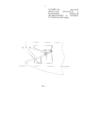
- схема устройства-прототипа, расположенного в проеме корпуса судна (фиг. 1),- diagram of the prototype device located in the opening of the hull (Fig. 1),
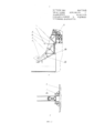
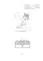
- предлагаемое спусковое устройство, установленное на стационарной буровой платформе (фиг. 2) вид сбоку - а), вид сверху - б),- the proposed launching device mounted on a stationary drilling platform (Fig. 2) side view - a), top view - b),
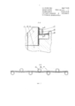
- спусковое устройство и спасательная шлюпка (сечения А-А и Б-Б) - фиг. 3,- launching device and lifeboat (sections AA and BB) - FIG. 3
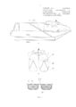
- спасательная шлюпка с амортизатором (фиг. 4), вид сбоку - а), вид спереди - б), сечение В-В,- a lifeboat with a shock absorber (Fig. 4), side view - a), front view - b), section B-B,
- спусковое устройство с установленным на нем амортизатором (фиг. 5), вид сбоку, сечение Г-Г.- trigger device with a shock absorber installed on it (Fig. 5), side view, section G-G.
В устройстве-прототипе для экстренной эвакуации персонала с бурового судна в ледовых условиях в кормовой оконечности судна 1 установлены параллельно друг другу лотки 2 с расположенными на них спасательными шлюпками 3. Устройство расположено в судовом помещении внутри корпуса судна, над ватерлинией, на высоте, обеспечивающей безопасный съезд по лотку на ледовую поверхность шлюпки с персоналом через проем в судовом корпусе. Выход шлюпок из помещения на лоток осуществляется с помощью откидной аппарели 4.In the prototype device for emergency evacuation of personnel from a drilling vessel in ice conditions at the aft end of the
Предлагаемое устройство для быстрой эвакуации персонала с надводных объектов океанотехники в ледовых условиях ориентировано на обеспечение в аварийной ситуации безопасного спуска на лед (воду) нескольких спасательных шлюпок с одного спускового устройства в виде стрелы 5 ферменной конструкции, шарнирно закрепленной на морской платформе 6. С помощью шарнирных опор 7, трособлочной системы 8 и привода 9, установленного на платформе, стрела может поворачиваться в вертикальной плоскости. В рабочем положении она располагается над поверхностью льда (воды) и опирается на два выдвижных регулируемых упора 10, закрепленных на стене платформы. Стрела содержит два направляющих бруса 11, по которым скользят полозья 12 спасательной шлюпки. Шлюпка с обеих боковых сторон опирается полозьями на направляющие брусья спускового устройства.The proposed device for the rapid evacuation of personnel from surface objects of ocean engineering in ice conditions is aimed at providing in an emergency situation the safe launching on ice (water) of several lifeboats from one launch device in the form of a
Шлюпка снабжена амортизатором, расположенным со стороны днища и представляющим собой, по крайней мере, две гибкие оболочки 13 из полимерных материалов - тканей из полиамидных волокон, пропитанных эластомерами (резиной или полиуретаном). Внутри гибких оболочек содержится деформируемый пенополиуретановый заполнитель 14. Гибкие оболочки выполнены в виде соединенных между собой цилиндрических и конических частей, ориентированных вдоль днища шлюпки. В носовой части шлюпки гибкие оболочки закреплены на жестких конструкциях шлюпки с помощью прижимных планок 15. Перемещения гибких оболочек в поперечном направлении ограничены гибким кожухом 16 из таких же полимерных материалов, охватывающим гибкие оболочки с деформируемым заполнителем и закрепленным на корпусе шлюпки с помощью прижимных планок.The boat is equipped with a shock absorber located on the bottom side and representing at least two
Спусковое устройство и спасательная шлюпка содержат элементы тормозной системы. Тормозная система состоит из расположенных в два ряда на каждом борту шлюпки в шахматном порядке упорных элементов 17 цилиндрической формы, неподвижно соединенных с полозьями спасательной шлюпки с помощью усиленной пластины 18, и двух изгибаемых полос 19, каждая из которых соединена с одним из направляющих брусов спускового устройства. Толщина изгибаемых полос является переменной как по длине, так и по ширине. Утолщенная (по ширине) часть изгибаемой полосы на большей части ее длины находится в контакте с упорными элементами движущейся шлюпки. Продольная кромка изгибаемой полосы, расположенная со стороны ее тонкой части, неподвижно соединена со стенкой бруса спускового устройства. Конец изгибаемой полосы в верхней части спускового устройства по всей ее ширине имеет одинаковую толщину, равную толщине тонкой части полосы в ее средней (по длине) части.The launching device and the lifeboat contain elements of the brake system. The brake system consists of
Уменьшение интенсивности удара спасательной шлюпки о ледовую поверхность достигается за счет торможения шлюпки, снижения скорости ее соударения, амортизации удара и увеличения площади действия нагрузок, возникающих при ударе шлюпки о лед. Такое увеличение площади достигается благодаря положению основной плоскости шлюпки в момент удара, близкому к горизонтальному. Это положение обеспечивается, если углы наклона полозьев спасательной шлюпки к ее основной плоскости отличаются от угла наклона направляющих плоскостей лотков к горизонту не более чем на 10°.The decrease in the impact intensity of the lifeboat on the ice surface is achieved by braking the boat, reducing the speed of its collision, shock absorption and increasing the area of action of the loads that occur when the boat hits the ice. This increase in area is achieved due to the position of the main plane of the boat at the moment of impact, close to horizontal. This position is ensured if the angles of inclination of the runners of the lifeboat to its main plane differ from the angle of inclination of the guide planes of the trays to the horizon by no more than 10 °.
Для обеспечения сброса шлюпок в зоне, расположенной за пределами возможного нагромождения льда перед объектом океанотехники, подхода судов к этим объектам и снижения вероятности обледенения низкорасположенных частей спускового устройства, возможного при действии ветра и волнения в условиях низких температур и отсутствия ледового покрова, спусковое устройство выполняется в виде стрелы ферменной конструкции. Его фиксация в верхнем (нерабочем) положении, в котором вероятность обледенения мала, и поворот в вертикальной плоскости осуществляются с помощью трособлочной системы.To ensure the dumping of boats in the area located beyond the possible accumulation of ice in front of the object of ocean engineering, the approach of ships to these objects and to reduce the likelihood of icing of the low-lying parts of the launching device, which is possible under the influence of wind and waves in low temperatures and the absence of ice cover, the launching device is performed form of truss arrow. Its fixation in the upper (inoperative) position, in which the probability of icing is small, and the rotation in the vertical plane are carried out using a cable block system.
На начальном участке сброса шлюпки между опорными элементами располагается конец изгибаемой полосы с малой толщиной, равной толщине тонкой части изгибаемой полосы. При положении шлюпки на этом участке полоса не деформируется. При последующем продвижении шлюпки вниз в контакт с упорными элементами вступает утолщенная часть полосы. При этом происходит упругопластический изгиб утолщенной части полосы и упругое деформирование ее тонкой части. В процессе такого изгиба возникают силы сопротивления движению шлюпки, вызванные трением и пластическим деформированием материала полосы, снижающие скорость спуска шлюпки по спусковому устройству. В конце спуска шлюпки в контакт со льдом (водой) вступает ее амортизатор. Благодаря амортизатору и тормозному устройству, уменьшающему скорость спуска шлюпки, интенсивность удара ее о ледовую поверхность (поверхность воды) снижается, уменьшаются силы, действующие на конструкции шлюпки.At the initial section of the discharge of the boat between the supporting elements is the end of the bending strip with a small thickness equal to the thickness of the thin part of the bending strip. With the position of the boat in this section, the strip is not deformed. When the boat is subsequently advanced downward, the thickened part of the strip comes into contact with the thrust elements. In this case, the elastoplastic bending of the thickened part of the strip and the elastic deformation of its thin part occur. In the process of such bending, resistance forces arise to the movement of the boat, caused by friction and plastic deformation of the strip material, reducing the speed of the boat lowering along the launching device. At the end of the launch of the boat, its shock absorber comes into contact with ice (water). Thanks to the shock absorber and the braking device, which reduces the speed of launching the boat, the intensity of its impact on the ice surface (water surface) is reduced, the forces acting on the structure of the boat are reduced.
По второму варианту исполнения спусковое устройство в нижней части содержит съемный амортизатор для безопасного спуска шлюпок. Амортизатор устанавливается на стрелу только при наличии ледового покрова водной поверхности. При этом оснащение спасательных шлюпок амортизатором не требуется. В этом варианте для исключения забрызгивания амортизатора морской водой и покрытия его льдом стрела спускового устройства и амортизатор при отсутствии аварийной обстановки переводятся в верхнее положение, при возникновении аварийной ситуации - в нижнее положение, обеспечивающее спуск шлюпок.According to the second embodiment, the launching device at the bottom contains a removable shock absorber for safe launching of boats. The shock absorber is installed on the boom only if there is ice cover on the water surface. However, equipping lifeboats with a shock absorber is not required. In this embodiment, to prevent splashing of the shock absorber with sea water and covering it with ice, the boom of the launching device and the shock absorber in the absence of an emergency situation are moved to the upper position, in the event of an emergency - to the lower position, which ensures the launch of the boats.
В таком варианте спусковое устройство снабжено амортизатором, расположенным на опорной раме 20, закрепленной на спусковом устройстве. Этот амортизатор по своему конструктивному оформлению подобен амортизатору, используемому в первом варианте устройства для быстрой эвакуации персонала и содержит, по крайней мере, две гибкие оболочки 21 из полимерных материалов - тканей из полиамидных волокон, пропитанных эластомерами (резиной или полиуретаном). Внутри оболочек содержится деформируемый заполнитель 22, выполненный из пенополиуретана. Перемещения этих гибких оболочек в поперечном направлении ограничиваются гибким кожухом 23, охватывающим гибкие оболочки с заполнителем и закрепленным на опорной раме.In this embodiment, the trigger device is equipped with a shock absorber located on the
В конце спуска шлюпка вступает в контакт с амортизатором, происходит их ударное взаимодействие, приводящее к снижению вертикальной скорости шлюпки и ее движению по инерции в горизонтальном направлении с последующим мягким контактом с ледовой поверхностью и скольжением по льду.At the end of the descent, the boat comes into contact with the shock absorber, their impact interaction occurs, leading to a decrease in the vertical speed of the boat and its inertial motion in the horizontal direction, followed by soft contact with the ice surface and sliding on ice.
Таким образом, предлагаемые варианты устройства для быстрой эвакуации персонала с надводных объектов океанотехники в ледовых условиях позволяют:Thus, the proposed device options for the rapid evacuation of personnel from surface objects of ocean engineering in ice conditions allow:
- существенно ускорить проведение операции спасения персонала из высокорасположенных помещений объектов,- significantly speed up the operation to rescue personnel from high-level facilities,
- снизить интенсивность удара спасательной шлюпки о ледовую поверхность (поверхность воды),- reduce the intensity of the impact of the lifeboat on the ice surface (water surface),
- уменьшить силы, действующие на ее конструкции, снизить вероятность разрушения, а также уменьшить перегрузки, испытываемые спасаемым персоналом при ударе, и вероятность гибели людей,- reduce the forces acting on its structure, reduce the likelihood of destruction, as well as reduce the overload experienced by the rescued personnel upon impact, and the likelihood of death of people,
- обеспечить возможность надежного функционирования системы в условиях выхода из строя системы электроснабжения, при пожарах и авариях.- to provide the possibility of reliable operation of the system in the event of failure of the power supply system, in case of fires and accidents.
Эти преимущества выгодно отличают предлагаемые варианты изобретения от прототипа.These advantages distinguish the proposed variants of the invention from the prototype.
Claims (8)
Priority Applications (1)
| Application Number | Priority Date | Filing Date | Title |
|---|---|---|---|
| RU2014128428/11A RU2575367C2 (en) | 2014-07-10 | Device of fast personnel evacuation from surface objects of ocean engineering under ice conditions (versions) |
Applications Claiming Priority (1)
| Application Number | Priority Date | Filing Date | Title |
|---|---|---|---|
| RU2014128428/11A RU2575367C2 (en) | 2014-07-10 | Device of fast personnel evacuation from surface objects of ocean engineering under ice conditions (versions) |
Publications (2)
| Publication Number | Publication Date |
|---|---|
| RU2014128428A RU2014128428A (en) | 2016-02-10 |
| RU2575367C2 true RU2575367C2 (en) | 2016-02-20 |
Family
ID=
Cited By (3)
| Publication number | Priority date | Publication date | Assignee | Title |
|---|---|---|---|---|
| RU2633834C1 (en) * | 2016-07-04 | 2017-10-18 | Владимир Васильевич Чернявец | Device for personnel evacuation from offshore drilling facilities |
| RU2720757C1 (en) * | 2019-11-28 | 2020-05-13 | Владимир Васильевич Чернявец | Complex emergency evacuation to ice of personnel and crew of offshore platforms |
| RU2808496C1 (en) * | 2023-04-04 | 2023-11-28 | Публичное акционерное общество "Нефтяная компания "Роснефть" (ПАО "НК "Роснефть") | Collective rescue device for use in ice conditions |
Citations (4)
| Publication number | Priority date | Publication date | Assignee | Title |
|---|---|---|---|---|
| SU1743985A1 (en) * | 1990-08-20 | 1992-06-30 | Научно-производственный центр при Николаевском кораблестроительном институте | Life-saving appliance of craft |
| RU16488U1 (en) * | 2000-09-26 | 2001-01-10 | Суханов Игорь Юрьевич | SHIP LIFTING LIFT |
| RU122364U1 (en) * | 2012-05-31 | 2012-11-27 | Российская Федерация, от имени которой выступает Министерство промышленности и торговли Российской Федерации (Минпромторг России) | DEVICE FOR EMERGENCY EMPLOYEES OF PERSONNEL FROM A DRILLING VESSEL IN ICE CONDITIONS |
| EP2692625A1 (en) * | 2012-08-02 | 2014-02-05 | RES Marina S.r.l. | Hyperbaric evacuation system for divers and hyperbaric chamber for evacuating divers |
Patent Citations (4)
| Publication number | Priority date | Publication date | Assignee | Title |
|---|---|---|---|---|
| SU1743985A1 (en) * | 1990-08-20 | 1992-06-30 | Научно-производственный центр при Николаевском кораблестроительном институте | Life-saving appliance of craft |
| RU16488U1 (en) * | 2000-09-26 | 2001-01-10 | Суханов Игорь Юрьевич | SHIP LIFTING LIFT |
| RU122364U1 (en) * | 2012-05-31 | 2012-11-27 | Российская Федерация, от имени которой выступает Министерство промышленности и торговли Российской Федерации (Минпромторг России) | DEVICE FOR EMERGENCY EMPLOYEES OF PERSONNEL FROM A DRILLING VESSEL IN ICE CONDITIONS |
| EP2692625A1 (en) * | 2012-08-02 | 2014-02-05 | RES Marina S.r.l. | Hyperbaric evacuation system for divers and hyperbaric chamber for evacuating divers |
Cited By (3)
| Publication number | Priority date | Publication date | Assignee | Title |
|---|---|---|---|---|
| RU2633834C1 (en) * | 2016-07-04 | 2017-10-18 | Владимир Васильевич Чернявец | Device for personnel evacuation from offshore drilling facilities |
| RU2720757C1 (en) * | 2019-11-28 | 2020-05-13 | Владимир Васильевич Чернявец | Complex emergency evacuation to ice of personnel and crew of offshore platforms |
| RU2808496C1 (en) * | 2023-04-04 | 2023-11-28 | Публичное акционерное общество "Нефтяная компания "Роснефть" (ПАО "НК "Роснефть") | Collective rescue device for use in ice conditions |
Similar Documents
| Publication | Publication Date | Title |
|---|---|---|
| KR101505460B1 (en) | Freefall life boat launching apparatus | |
| KR101487296B1 (en) | Apparatus and Method for Launching Life Boat for Offshore Structure | |
| EP0255191A1 (en) | Personnel evacuation apparatus for an offshore platform | |
| EP1910164B1 (en) | Gangway apparatus | |
| RU2680232C2 (en) | Buoyant structure | |
| KR101497444B1 (en) | Apparatus for Launching Life Boat for Offshore Structure | |
| DK3003846T3 (en) | Boat mounting | |
| US20090158991A1 (en) | Device, System, Structure, Method, Computer Program Product and Control System | |
| RU2467915C2 (en) | Method of locating and using of universal rescue surface complex | |
| US3880254A (en) | Escape boom | |
| RU2575367C2 (en) | Device of fast personnel evacuation from surface objects of ocean engineering under ice conditions (versions) | |
| KR101644571B1 (en) | Apparatus for launching life boat in floating structure | |
| RU2633834C1 (en) | Device for personnel evacuation from offshore drilling facilities | |
| RU2583828C1 (en) | System for collective rescue of personnel from offshore oil and gas facilities in ice conditions | |
| KR101616830B1 (en) | Lifeboat launching device | |
| KR20140131406A (en) | Apparatus and Method for Launching Life Boat for Offshore Structure | |
| KR20140004399A (en) | Lifeboat housing structure | |
| KR101563663B1 (en) | Helicopter deck apparatus | |
| RU2740323C1 (en) | Crew rescue facility lifeboat launching device | |
| NO20161990A1 (en) | Boat transfer system | |
| RU2614166C2 (en) | Launch device of lifeboat for personnel at offshore oil and gas facilities in ice conditions | |
| Kryzhevich | Appliances for Quick Personnel Evacuation from Offshore Structures in Ice Conditions | |
| RU2651960C2 (en) | Rescue device for evacuation of personnel of marine oil and gas-oil constructions in ice conditions | |
| RU155213U1 (en) | MARINE EVACUATION SYSTEM | |
| KR20160146388A (en) | Lifeboat launching device |