RU2566862C1 - Filter body and filtering unit for air for internal combustion engine - Google Patents
Filter body and filtering unit for air for internal combustion engine Download PDFInfo
- Publication number
- RU2566862C1 RU2566862C1 RU2014139672/06A RU2014139672A RU2566862C1 RU 2566862 C1 RU2566862 C1 RU 2566862C1 RU 2014139672/06 A RU2014139672/06 A RU 2014139672/06A RU 2014139672 A RU2014139672 A RU 2014139672A RU 2566862 C1 RU2566862 C1 RU 2566862C1
- Authority
- RU
- Russia
- Prior art keywords
- filter
- air
- housing
- filter unit
- engine
- Prior art date
Links
Images


Classifications
-
- F—MECHANICAL ENGINEERING; LIGHTING; HEATING; WEAPONS; BLASTING
- F02—COMBUSTION ENGINES; HOT-GAS OR COMBUSTION-PRODUCT ENGINE PLANTS
- F02M—SUPPLYING COMBUSTION ENGINES IN GENERAL WITH COMBUSTIBLE MIXTURES OR CONSTITUENTS THEREOF
- F02M35/00—Combustion-air cleaners, air intakes, intake silencers, or induction systems specially adapted for, or arranged on, internal-combustion engines
- F02M35/02—Air cleaners
- F02M35/024—Air cleaners using filters, e.g. moistened
- F02M35/02416—Fixing, mounting, supporting or arranging filter elements; Filter element cartridges
-
- B—PERFORMING OPERATIONS; TRANSPORTING
- B01—PHYSICAL OR CHEMICAL PROCESSES OR APPARATUS IN GENERAL
- B01D—SEPARATION
- B01D46/00—Filters or filtering processes specially modified for separating dispersed particles from gases or vapours
- B01D46/0002—Casings; Housings; Frame constructions
- B01D46/0004—Details of removable closures, lids, caps or filter heads
-
- B—PERFORMING OPERATIONS; TRANSPORTING
- B01—PHYSICAL OR CHEMICAL PROCESSES OR APPARATUS IN GENERAL
- B01D—SEPARATION
- B01D46/00—Filters or filtering processes specially modified for separating dispersed particles from gases or vapours
- B01D46/0002—Casings; Housings; Frame constructions
- B01D46/0005—Mounting of filtering elements within casings, housings or frames
-
- B—PERFORMING OPERATIONS; TRANSPORTING
- B01—PHYSICAL OR CHEMICAL PROCESSES OR APPARATUS IN GENERAL
- B01D—SEPARATION
- B01D46/00—Filters or filtering processes specially modified for separating dispersed particles from gases or vapours
- B01D46/24—Particle separators, e.g. dust precipitators, using rigid hollow filter bodies
- B01D46/2403—Particle separators, e.g. dust precipitators, using rigid hollow filter bodies characterised by the physical shape or structure of the filtering element
- B01D46/2411—Filter cartridges
- B01D46/2414—End caps including additional functions or special forms
-
- B—PERFORMING OPERATIONS; TRANSPORTING
- B01—PHYSICAL OR CHEMICAL PROCESSES OR APPARATUS IN GENERAL
- B01D—SEPARATION
- B01D46/00—Filters or filtering processes specially modified for separating dispersed particles from gases or vapours
- B01D46/42—Auxiliary equipment or operation thereof
- B01D46/48—Removing dust other than cleaning filters, e.g. by using collecting trays
-
- B—PERFORMING OPERATIONS; TRANSPORTING
- B01—PHYSICAL OR CHEMICAL PROCESSES OR APPARATUS IN GENERAL
- B01D—SEPARATION
- B01D46/00—Filters or filtering processes specially modified for separating dispersed particles from gases or vapours
- B01D46/88—Replacing filter elements
-
- F—MECHANICAL ENGINEERING; LIGHTING; HEATING; WEAPONS; BLASTING
- F02—COMBUSTION ENGINES; HOT-GAS OR COMBUSTION-PRODUCT ENGINE PLANTS
- F02M—SUPPLYING COMBUSTION ENGINES IN GENERAL WITH COMBUSTIBLE MIXTURES OR CONSTITUENTS THEREOF
- F02M35/00—Combustion-air cleaners, air intakes, intake silencers, or induction systems specially adapted for, or arranged on, internal-combustion engines
- F02M35/02—Air cleaners
- F02M35/024—Air cleaners using filters, e.g. moistened
- F02M35/02475—Air cleaners using filters, e.g. moistened characterised by the shape of the filter element
- F02M35/02483—Cylindrical, conical, oval, spherical or the like filter elements; wounded filter elements
-
- F—MECHANICAL ENGINEERING; LIGHTING; HEATING; WEAPONS; BLASTING
- F02—COMBUSTION ENGINES; HOT-GAS OR COMBUSTION-PRODUCT ENGINE PLANTS
- F02M—SUPPLYING COMBUSTION ENGINES IN GENERAL WITH COMBUSTIBLE MIXTURES OR CONSTITUENTS THEREOF
- F02M35/00—Combustion-air cleaners, air intakes, intake silencers, or induction systems specially adapted for, or arranged on, internal-combustion engines
- F02M35/02—Air cleaners
- F02M35/04—Air cleaners specially arranged with respect to engine, to intake system or specially adapted to vehicle; Mounting thereon ; Combinations with other devices
- F02M35/048—Arranging or mounting on or with respect to engines or vehicle bodies
-
- B—PERFORMING OPERATIONS; TRANSPORTING
- B01—PHYSICAL OR CHEMICAL PROCESSES OR APPARATUS IN GENERAL
- B01D—SEPARATION
- B01D2271/00—Sealings for filters specially adapted for separating dispersed particles from gases or vapours
- B01D2271/02—Gaskets, sealings
- B01D2271/022—Axial sealings
-
- F—MECHANICAL ENGINEERING; LIGHTING; HEATING; WEAPONS; BLASTING
- F02—COMBUSTION ENGINES; HOT-GAS OR COMBUSTION-PRODUCT ENGINE PLANTS
- F02M—SUPPLYING COMBUSTION ENGINES IN GENERAL WITH COMBUSTIBLE MIXTURES OR CONSTITUENTS THEREOF
- F02M35/00—Combustion-air cleaners, air intakes, intake silencers, or induction systems specially adapted for, or arranged on, internal-combustion engines
- F02M35/02—Air cleaners
- F02M35/0201—Housings; Casings; Frame constructions; Lids; Manufacturing or assembling thereof
- F02M35/0202—Manufacturing or assembling; Materials for air cleaner housings
- F02M35/0203—Manufacturing or assembling; Materials for air cleaner housings by using clamps, catches, locks or the like, e.g. for disposable plug-in filter cartridges
-
- F—MECHANICAL ENGINEERING; LIGHTING; HEATING; WEAPONS; BLASTING
- F02—COMBUSTION ENGINES; HOT-GAS OR COMBUSTION-PRODUCT ENGINE PLANTS
- F02M—SUPPLYING COMBUSTION ENGINES IN GENERAL WITH COMBUSTIBLE MIXTURES OR CONSTITUENTS THEREOF
- F02M35/00—Combustion-air cleaners, air intakes, intake silencers, or induction systems specially adapted for, or arranged on, internal-combustion engines
- F02M35/02—Air cleaners
- F02M35/0201—Housings; Casings; Frame constructions; Lids; Manufacturing or assembling thereof
- F02M35/0209—Housings; Casings; Frame constructions; Lids; Manufacturing or assembling thereof comprising flexible, resilient, movable or rotatable elements, e.g. with vibrating or contracting movements; Springs; Valves; Flaps
Abstract
Description
Область техникиTechnical field
Изобретение относится к корпусу фильтра для размещения фильтровального блока, содержащего впускной патрубок для воздуха и выпускной патрубок для воздуха, идущего к двигателю. Изобретение относится также к фильтровальному блоку для такого корпуса воздушного фильтра.The invention relates to a filter housing for accommodating a filter unit containing an inlet pipe for air and an outlet pipe for air going to the engine. The invention also relates to a filter unit for such an air filter housing.
Уровень техникиState of the art
В известных устройствах воздушного фильтра для двигателя внутреннего сгорания грузовой машины корпус фильтра часто имеет съемную нижнюю часть, которая позволяет вынимать и заменять использованный фильтровальный блок снизу, то есть с нижней грязной стороны устройства. Хотя смена фильтра происходит с грязной стороны, все еще существует риск того, что в ограниченном пространстве под транспортным средством новый фильтровальный блок может быть поцарапан о загрязненную область внутри и снаружи корпуса фильтра, что потенциально приводит к попаданию грязи в фильтровальный блок и, таким образом, к чистой стороне воздушной системы и, следовательно, к возможному повреждению двигателя. Такая замена фильтра также включает в себя большие трудозатраты и использование пространства, в особенности, когда транспортное средство необходимо поднимать или размещать поверх смотровой ямы или тому подобного в автомастерской для обеспечения пространства для работы по замене. Операция может содержать снятие нижней части корпуса фильтра, вынимание использованного фильтровального блока, очищение внутренней части и нижней части корпуса, вставление нового фильтровального блока и повторную установку нижней части.In known air filter devices for an internal combustion engine of a truck, the filter housing often has a removable lower part, which allows you to remove and replace the used filter unit from the bottom, that is, from the bottom dirty side of the device. Although the filter is replaced on the dirty side, there is still a risk that, in the limited space under the vehicle, the new filter unit may be scratched on a contaminated area inside and outside the filter housing, which potentially leads to dirt entering the filter unit and thus to the clean side of the air system and therefore to possible engine damage. Such a filter change also includes a lot of labor and space, especially when the vehicle needs to be lifted or placed over a viewing hole or the like in a car workshop to provide space for replacement work. The operation may include removing the lower part of the filter housing, removing the used filter unit, cleaning the inside and bottom of the housing, inserting a new filter unit and reinstalling the lower part.
Сущность изобретенияSUMMARY OF THE INVENTION
Задачей изобретения является разработка фильтровального устройства такого типа, который описан во введении, в котором фильтровальный блок может быть заменен более простым способом с малым риском загрязнения чистой стороны фильтровального устройства.The objective of the invention is to develop a filter device of the type described in the introduction, in which the filter unit can be replaced in a simpler way with little risk of contamination of the clean side of the filter device.
Это достигается с помощью отличительных признаков, описанных в прилагаемой формуле изобретения.This is achieved using the distinguishing features described in the attached claims.
В одном аспекте изобретения корпус фильтра имеет верхнее отверстие для введения и вынимания фильтровального блока, нижнее отверстие, выполненное с возможностью быть закрытым/открытым посредством вставляемой/вынимаемой закрытой нижней части фильтровального блока, и крышку для закрытия верхнего отверстия.In one aspect of the invention, the filter housing has an upper opening for inserting and removing the filter unit, a lower opening configured to be closed / open by the insertion / removal of the closed lower part of the filter unit, and a cover for closing the upper opening.
Таким образом, это устройство допускает смену фильтровального блока с верхней стороны корпуса фильтра, упрощая тем самым работу и исключая необходимость поднятия транспортного средства или размещения его на смазочном посту или поверх смотровой ямы. Нижнее отверстие также облегчает очистку внутренней части корпуса фильтра сверху, так что извлекаемая грязь может выходить через нижнее отверстие. Перемещение по направлению вниз после очистки, выполняемое при вставлении нового фильтровального блока, означает, что по направлению к чистой стороне корпуса фильтра загрязнение не будет перемещаться. Тот факт, что нижняя часть фильтровального блока закрывает нижнее отверстие, означает также, что корпус фильтра не нуждается в съемной нижней части.Thus, this device allows the filter unit to be replaced on the upper side of the filter housing, thereby simplifying operation and eliminating the need to raise the vehicle or place it at a lubricating station or over a viewing hole. The lower hole also facilitates cleaning the inside of the filter housing from above, so that the extracted dirt can exit through the lower hole. A downward movement after cleaning, performed when a new filter unit is inserted, means that no dirt will move towards the clean side of the filter housing. The fact that the lower part of the filter unit covers the lower hole also means that the filter housing does not need a removable lower part.
Хотя возможны другие решения, в одном варианте осуществления выпускной патрубок для воздуха, идущего к двигателю, расположен в крышке. Крышка может быть различными способами выполнена с возможностью снятия и отделения от остальной части корпуса фильтра, чтобы позволить смену фильтра без удаления трубопроводов для воздуха между двигателем и крышкой. Крышка может быть, например, удалена посредством перемещения вдоль и поворота вокруг одного или более соединений трубопроводов. Она также может быть соединена с гибкой трубной секцией, такой так сильфон, например сужающийся сильфон, который может быть вывернут наизнанку, подобно сворачиваемому сильфону, так, чтобы он становился короче, когда крышка удаляется достаточно далеко, чтобы допустить смену фильтра с верхней стороны корпуса фильтра.Although other solutions are possible, in one embodiment, the exhaust pipe for air to the engine is located in the cover. The cover can be made in various ways with the possibility of removal and separation from the rest of the filter housing to allow the filter to be changed without removing the air piping between the engine and the cover. The cover may, for example, be removed by moving along and pivoting around one or more pipe connections. It can also be connected to a flexible pipe section, such a bellows, for example a tapering bellows, which can be turned inside out, like a collapsible bellows, so that it becomes shorter when the cover is removed far enough to allow the filter to change from the top of the filter housing .
Выпускной патрубок для воздуха, идущего к двигателю, также может быть покрыт фильтровальным элементом. Такой фильтровальный элемент, который может содержать фильтровальную ткань или мелкоячеистую сетку на крышке, может обеспечивать защиту от загрязнения чистой стороны с патрубками, идущими к двигателю, когда крышка удаляется для смены фильтра.The exhaust pipe for air going to the engine can also be covered with a filter element. Such a filter element, which may comprise a filter cloth or a fine mesh on the cover, can provide protection against contamination of the clean side with nozzles leading to the engine when the cover is removed to change the filter.
Фильтровальный блок в соответствии с изобретением для корпуса фильтра с впускным патрубком для воздуха и выпускным патрубком для воздуха, идущего к двигателю, содержит по существу полуцилиндрический воздушный фильтр. Фильтровальный блок характеризуется закрытой нижней частью фильтра, выполненной с возможностью закрывания нижнего отверстия корпуса фильтра при введении фильтровального блока в корпус.The filter unit in accordance with the invention for a filter housing with an air inlet and an exhaust port for air to the engine comprises a substantially semi-cylindrical air filter. The filter unit is characterized by a closed lower part of the filter, configured to close the lower opening of the filter housing when the filter unit is inserted into the housing.
Фильтровальный блок может иметь центрирующее средство на периферии нижней части фильтра для вхождения в контактное взаимодействие с кромкой нижнего отверстия, упрощая и обеспечивая достижение правильного положения нижней части фильтра при смене фильтра.The filter unit may have centering means at the periphery of the lower part of the filter to engage in contact with the edge of the lower hole, simplifying and ensuring that the correct position of the lower part of the filter is achieved when changing the filter.
Хотя крышка корпуса фильтра может служить в качестве верхнего уплотнения между грязной и чистой стороной фильтровального блока, фильтровальный блок в одном варианте осуществления также имеет верхнюю часть фильтра, имеющую центральное отверстие для выпускного патрубка для воздуха, идущего к двигателю, выполненную с возможностью закрытия верхнего отверстия корпуса фильтра, когда фильтровальный блок вставляется в корпус фильтра.Although the filter housing cover can serve as an upper seal between the dirty and clean side of the filter block, the filter block in one embodiment also has a filter top having a central opening for an exhaust port for air to the engine configured to close the upper opening of the housing filter when the filter unit is inserted into the filter housing.
Верхняя часть фильтра и нижняя часть фильтра нового фильтровального блока могут, таким образом, образовывать и герметизировать грязную сторону корпуса фильтра, то есть кольцевое входное пространство между фильтром и корпусом фильтра, как только новый фильтровальный блок устанавливается в рабочее положение в корпусе фильтра, так что не существует риска загрязнения чистой стороны, когда крышка возвращается на место.The upper part of the filter and the lower part of the filter of the new filter unit can thus form and seal the dirty side of the filter housing, i.e. the annular inlet space between the filter and the filter housing, as soon as the new filter unit is installed in the working position in the filter housing, so that There is a risk of contamination of the clean side when the cover is replaced.
В другом варианте осуществления верхняя сторона верхней части фильтра может быть выполнена с возможностью образования совместно с крышкой корпуса фильтра воздушного отверстия к патрубку для добавочного воздуха корпуса фильтра, которое проходит вдоль периферии выпускного патрубка для воздуха, идущего к двигателю. Это позволяет отфильтрованному воздуху проходить из корпуса фильтра к потребителям, другим, нежели двигатель, например к воздушному компрессору.In another embodiment, the upper side of the upper part of the filter may be configured to form, together with the cover of the filter housing, an air hole to the secondary housing of the filter housing, which extends along the periphery of the air outlet to the engine. This allows filtered air to pass from the filter housing to consumers other than the engine, such as an air compressor.
Фильтровальный блок может иметь центрирующее средство на периферии верхней части фильтра для вхождения в контактное взаимодействие с кромкой верхнего отверстия, упрощая и обеспечивая достижение правильного положения верхней части фильтра при смене фильтра.The filter unit may have centering means on the periphery of the upper part of the filter to engage in contact with the edge of the upper hole, simplifying and ensuring that the correct position of the upper part of the filter is achieved when changing the filter.
Другие признаки и преимущества изобретения могут быть понятны из формулы изобретения и описания примеров вариантов изобретения, приведенных далее.Other features and advantages of the invention can be understood from the claims and the description of examples of embodiments of the invention below.
Краткое описание чертежейBrief Description of the Drawings
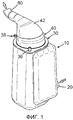
Фиг. 1 - наклонный вид сверху устройства воздушного фильтра в соответствии с изобретением;FIG. 1 is an oblique top view of an air filter device in accordance with the invention;
Фиг. 2 - продольное сечение вида, соответствующего Фиг. 1, с открытой крышкой;FIG. 2 is a longitudinal section of a view corresponding to FIG. 1, with the lid open;
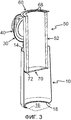
Фиг. 3 - продольное сечение вида, приблизительно как на Фиг. 2, с воздушным фильтром, частично вытянутым наружу;FIG. 3 is a longitudinal sectional view, approximately as in FIG. 2, with an air filter partially elongated outward;
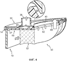
Фиг. 4 - детальное изображение с отрезанными частями верхней части устройства воздушного фильтра в соответствии с изобретением;FIG. 4 is a detailed image with cut off parts of the upper part of the air filter device in accordance with the invention;
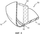
Фиг. 5 - детальное изображение с отрезанными частями нижней части устройства воздушного фильтра в соответствии с изобретением;FIG. 5 is a detailed image with cut off parts of the lower part of the air filter device in accordance with the invention;
Фиг. 6 - вид сбоку с отрезанными частями верхней части устройства воздушного фильтра в соответствии с изобретением с закрытой крышкой;FIG. 6 is a side view with cut off parts of the upper part of the air filter device in accordance with the invention with the lid closed;
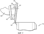
Фиг. 7 - вид, соответствующий фиг. 6, с открытой крышкой; иFIG. 7 is a view corresponding to FIG. 6, with the lid open; and
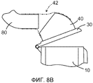
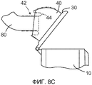
Фиг. 8А-8С - схематическая иллюстрация процесса открытия крышки устройства по существу в соответствии с фиг. 6 и 7.FIG. 8A-8C is a schematic illustration of a process for opening a lid of a device substantially in accordance with FIG. 6 and 7.
На всех чертежах одинаковыми ссылочными позициями обозначены элементы с одинаковыми или похожими функциями.In all the drawings, the same reference numerals denote elements with the same or similar functions.
Подробное описание вариантов осуществленияDetailed Description of Embodiments
Устройство воздушного фильтра, изображенное на чертежах, содержит известный удлиненный корпус 10 воздушного фильтра для размещения фильтровального блока или картриджа 50, содержащего по существу полуцилиндрический воздушный фильтр 52. Предназначенный для фильтрации воздух проходит через впускной патрубок 20 для воздуха (фиг. 1), расположенный на наружной стороне корпуса 10 фильтра, в кольцевое пространство между фильтровальным блоком 50 и корпусом 10 фильтра и, после прохождения через фильтр 52, проходит через выпускной патрубок 40 для воздуха, идущего к двигателю, в крышке 30 на верхней стороне корпуса 10 фильтра. Этот выпускной патрубок 40 для воздуха, идущего к двигателю, сам предназначен для соединения с непоказанным впускным элементом двигателя внутреннего сгорания через последовательно расположенные трубные секции 42 для воздуха.The air filter device shown in the drawings contains a known elongated
Как наиболее ясно показано на фиг. 4, фильтр 52 фильтровального блока 50 соединен с верхней частью фильтра в форме верхнего уплотнительного элемента 60, который имеет центральное отверстие 62, коаксиальное с внутренней стороной фильтра 52 и с выпускным патрубком 40 для воздуха, идущего к двигателю. Когда фильтровальный блок 50 вставлен в корпус 10, наружная периферия уплотнительного элемента 60 плотно примыкает к кромке 14, которая образует верхнее отверстие 12 корпуса. Центрирующее средство корпуса 10 фильтра и/или верхняя часть фильтра, например кольцевой выступ 67, направленный вниз от нижней стороны верхней части фильтра, может упрощать и обеспечивать достижение правильного положения верхней части фильтра на верхней стороне корпуса 10.As most clearly shown in FIG. 4, the
Между верхним уплотнительным элементом 60 фильтровального блока 50 и выпускным патрубком 40 для воздуха, идущего к двигателю, расположено воздушное отверстие 64 (фиг. 4) к выпускному патрубку 36 для добавочного воздуха. Как показано стрелками на фиг. 4, часть фильтруемого воздуха может быть также направлена к кольцевому каналу 66 через воздушное отверстие 64 между крышкой 30 и верхним уплотнительным элементом 60 до того, как он выйдет наружу через выпускной патрубок 36 для добавочного воздуха. Канал 66 может быть образован радиально наружу посредством кольцевого выступа 69, который является частью верхнего уплотнительного элемента 60 и который плотно примыкает к крышке 30. В показанном примере выпускной патрубок 36 для добавочного воздуха, который может направлять отфильтрованный в устройстве воздух к непоказанному потребителю воздуха, такому как, например, воздушный компрессор, расположен в крышке 30 корпуса 10 фильтра. Воздушное отверстие 64 проходит вдоль периферии выпускного патрубка 40 для воздуха, идущего к двигателю, преимущественно вокруг всей периферии в форме зазора, который проходит наклонно наружу и вверх. Ширина зазора может обеспечиваться посредством опор, например множеством равномерно распределенных выпуклостей 68, которые по желанию могут быть расположены на верхнем уплотнительном элементе 60 (фиг. 3) или на крышке 30.Between the
Как наиболее ясно проиллюстрировано посредством упрощенного изображения на фиг. 5, фильтр 52 фильтровального блока 50 также соединен с нижней частью фильтра в форме нижнего уплотнительного элемента 70. Когда фильтровальный блок 50 установлен в корпус 10, наружная периферия нижнего уплотнительного элемента 70 плотно прилегает к нижней кольцевой кромке 18, которая образует нижнее отверстие 16 (фиг. 3) корпуса. Это нижнее отверстие 16 позволяет удалять грязь, чистящее средство и другие частицы из корпуса 10 фильтра во время его очистки, например, в случае смены фильтровального блока 50. Центрирующее средство корпуса 10 и/или нижней части фильтра, например кольцевой выступ 72, направленный вниз от нижней стороны нижней части фильтра, может облегчать и обеспечивать достижение правильного положения нижней части фильтра на нижней стороне корпуса 10.As most clearly illustrated by the simplified image in FIG. 5, the
Хотя возможны другие решения, на фиг. 1-3 и фиг. 6-7 показана вышеупомянутая крышка 30, соединенная с возможностью поворота с корпусом 10 фильтра через шарнир 38, расположенный на верхней наружной стороне корпуса 10. Выпускной патрубок 40 для воздуха крышки 30 может быть дополнительно покрыт фильтровальным элементом 34 (фиг. 2), например фильтровальной тканью и/или мелкоячеистой сеткой для предотвращения попадания загрязнений и твердых частиц в выпускные патрубки 40, 80 для воздуха, когда крышка 30 открыта. Крышка 30 может быть прикреплена к корпусу 10 посредством подходящего крепежного средства, например, посредством непоказанных затяжных болтов или других типов крепежа.Although other solutions are possible, in FIG. 1-3 and FIG. 6 to 7, the
В варианте осуществления, показанном на фиг. 6 и 7, патрубок 40 для воздуха, расположенный рядом с крышкой 30, имеет сжимаемую или гибкую трубную секцию 42, которая выполнена с возможностью повторного открытия или закрытия крышки 30 без извлечения или перемещения неподвижного патрубка 80 для воздуха, расположенного рядом с двигателем. В показанном варианте осуществления трубная секция 42 имеет сужающуюся искривленную часть С, выполненную из сгибаемого каучукового упругого материала, который, подобно сворачиваемому сильфону, позволяет части с большим поперечным сечением, расположенной рядом с крышкой 30, быть вывернутой наружу, с помощью или без помощи специалиста по сервису, поверх части с сужающимся поперечным сечением, расположенной рядом с патрубком 80 для воздуха, приблизительно так, как показано на фиг. 7, когда крышка 30 открывается. В рабочем состоянии трубная секция 42 растянута поверх выпускного патрубка 40 для воздуха, идущего к двигателю, и патрубка 80 для воздуха. Средняя линия искривленной части может тогда проходить приблизительно на одинаковом расстоянии R от крышки шарнира 38.In the embodiment shown in FIG. 6 and 7, an
На фиг. 8А-8С более подробно показан процесс открывания устройства, по существу соответствующий процессу, показанному на фиг. 6 и 7. Выпускные патрубки 40 и 80 для воздуха проходят относительно далеко в гибкую трубную секцию 42 для того, чтобы ее поддерживать и предотвращать ее сплющивание во время работы. Как показано на фиг. 8В, часть с поперечным сечением трубной секции 42 между патрубками может быть образована различными путями, например посредством надрезов материала или посредством остаточных напряжений, с возможностью некоторого подтягивания или деформирования радиально вовнутрь, когда крышка 30 начинает открываться. Более крупный патрубок 40, соединенный с крышкой 30, будет тогда располагаться вокруг более узкого патрубка 80 и на расстоянии от него. Когда в дальнейшем крышка из фиг. 8С достигнет открытого состояния, которое позволяет извлекать непоказанный фильтровальный блок из корпуса 10 фильтра, на части трубной секции 42, которая опирается на концевую часть более узкого патрубка 80, может быть естественно образован лепесток 44 так, чтобы трубная секция 42 разворачивалась подобно сворачиваемому сильфону на этой концевой части.In FIG. 8A-8C show in more detail the process of opening the device, essentially corresponding to the process shown in FIG. 6 and 7.
В настоящем или в других вариантах осуществления крышка 30 не обязательно должна быть шарнирно прикреплена к остальной части корпуса 10, так как она также может быть полностью снята с корпуса 10 посредством непоказанного способа.In the present or other embodiments, the
Приведенное выше подробное описание главным образом предназначено для облегчения понимания, и из него не должны следовать не нужные ограничения изобретения. Модификации, которые будут очевидны для специалистов в данной области техники после изучения описания, могут быть выполнены в пределах сущности или объема прилагаемой формулы изобретения.The above detailed description is mainly intended to facilitate understanding and should not result in unnecessary limitations of the invention. Modifications that will be apparent to those skilled in the art after studying the description may be made within the spirit or scope of the appended claims.
Claims (9)
верхнее отверстие (12) для введения и вынимания фильтровального блока (50);
нижнее отверстие (16), выполненное с возможностью закрытия и открытия посредством закрытой нижней части фильтра соответственно вводимого или вынимаемого фильтровального блока (50); и
крышку (30) для закрытия верхнего отверстия (12).1. The filter housing (10) for the filter unit (50) with a substantially semi-cylindrical air filter (52), comprising an inlet pipe (20) for air and an outlet pipe (40) for air going to the engine, characterized in that it contains :
an upper hole (12) for inserting and removing the filter unit (50);
a lower hole (16) configured to close and open by means of the closed lower part of the filter, respectively, the inserted or taken out filter unit (50); and
a cover (30) for closing the upper hole (12).
Applications Claiming Priority (3)
| Application Number | Priority Date | Filing Date | Title |
|---|---|---|---|
| SE1250192-0 | 2012-03-01 | ||
| SE1250192A SE536436C2 (en) | 2012-03-01 | 2012-03-01 | Filter housing and air filter unit for an internal combustion engine |
| PCT/SE2013/050161 WO2013129997A1 (en) | 2012-03-01 | 2013-02-25 | Filter housing and air filter unit for a combustion engine |
Publications (1)
| Publication Number | Publication Date |
|---|---|
| RU2566862C1 true RU2566862C1 (en) | 2015-10-27 |
Family
ID=49083062
Family Applications (1)
| Application Number | Title | Priority Date | Filing Date |
|---|---|---|---|
| RU2014139672/06A RU2566862C1 (en) | 2012-03-01 | 2013-02-25 | Filter body and filtering unit for air for internal combustion engine |
Country Status (10)
| Country | Link |
|---|---|
| US (1) | US20150020486A1 (en) |
| EP (1) | EP2820289B1 (en) |
| JP (1) | JP5992543B2 (en) |
| KR (1) | KR102037366B1 (en) |
| CN (1) | CN104160140B (en) |
| BR (1) | BR112014021147B1 (en) |
| IN (1) | IN2014DN06604A (en) |
| RU (1) | RU2566862C1 (en) |
| SE (1) | SE536436C2 (en) |
| WO (1) | WO2013129997A1 (en) |
Families Citing this family (8)
| Publication number | Priority date | Publication date | Assignee | Title |
|---|---|---|---|---|
| EP3229936B1 (en) * | 2014-12-10 | 2019-12-18 | UFI Filters S.p.A. | A filter group of air directed to an air aspiration intake of an internal combustion engine |
| CN104948358A (en) * | 2015-07-13 | 2015-09-30 | 常州市宏硕电子有限公司 | Air cleaner element |
| FR3055369B1 (en) * | 2016-09-01 | 2020-06-19 | Peugeot Citroen Automobiles Sa | IMPROVED COVERED AIR FILTER FOR AN INTERNAL COMBUSTION ENGINE INTAKE LINE |
| US20190247780A1 (en) * | 2018-02-12 | 2019-08-15 | Dan Conrad | Easy change filter system For a Vehicle |
| KR102576431B1 (en) | 2018-09-10 | 2023-09-08 | 삼성디스플레이 주식회사 | Manufaturing device of organic and method for manufacturing organic using the same |
| KR20210054608A (en) * | 2019-11-05 | 2021-05-14 | 현대자동차주식회사 | Air cleaner for vehicle |
| DE102020103044A1 (en) * | 2020-02-06 | 2021-08-12 | Mann+Hummel Gmbh | Filter element for an air filter with a primary air outlet and a secondary air outlet and air filter and assembly method |
| KR20240048162A (en) | 2022-10-06 | 2024-04-15 | 호원산업개발주식회사 | Emergency sign-board |
Citations (6)
| Publication number | Priority date | Publication date | Assignee | Title |
|---|---|---|---|---|
| FR2255933B1 (en) * | 1973-12-27 | 1978-04-21 | Sofep | |
| RU2136945C1 (en) * | 1998-04-29 | 1999-09-10 | Открытое акционерное общество "ГАЗ" | Air cleaner of internal combustion engine |
| JP2005155452A (en) * | 2003-11-26 | 2005-06-16 | Honda Motor Co Ltd | Air cleaner |
| US20050284118A1 (en) * | 2004-06-23 | 2005-12-29 | Komatsu Ltd. | Air cleaner |
| RU86980U1 (en) * | 2009-02-26 | 2009-09-20 | ООО "Автокомпонент" | INTERNAL COMBUSTION ENGINE AIR FILTER |
| US20110259199A1 (en) * | 2008-11-20 | 2011-10-27 | Mann+Hummel Gmbh | Intake Air Filter for Internal Combustion Engines |
Family Cites Families (30)
| Publication number | Priority date | Publication date | Assignee | Title |
|---|---|---|---|---|
| JPH0232864Y2 (en) * | 1985-03-01 | 1990-09-05 | ||
| JPS6377506A (en) * | 1986-09-18 | 1988-04-07 | ハワ−ド・テイ−・デグラ−フエンライド | Filter cartridge and filter device |
| JPH0135209Y2 (en) * | 1987-06-11 | 1989-10-26 | ||
| JPH0414099Y2 (en) * | 1987-09-18 | 1992-03-31 | ||
| JPH0534469Y2 (en) * | 1988-06-14 | 1993-08-31 | ||
| JPH0672620U (en) * | 1993-03-29 | 1994-10-11 | 三菱樹脂株式会社 | Filter element |
| JPH0738655U (en) * | 1993-12-20 | 1995-07-14 | 東京濾器株式会社 | Air cleaner |
| US5512086A (en) * | 1994-06-14 | 1996-04-30 | Appliance Development Corporation | High-efficiency air filtering apparatus |
| US5556440A (en) * | 1994-10-20 | 1996-09-17 | Fleetguard, Inc. | Pressure-actuated radial air filter seal |
| US5445734A (en) * | 1994-11-18 | 1995-08-29 | Chen; Ching-Wen | Water filter |
| US5568800A (en) * | 1995-01-24 | 1996-10-29 | Einaudi; Luis E. | Fuel combustion enhancer |
| US5984991A (en) * | 1996-01-25 | 1999-11-16 | Appliance Development Corp. | High-efficiency air filter |
| JP3720150B2 (en) * | 1996-10-31 | 2005-11-24 | 本田技研工業株式会社 | Air cleaner |
| US5919279A (en) * | 1998-01-30 | 1999-07-06 | Baldwin Filters, Inc. | Self contained heavy-duty air filter |
| JP2001162112A (en) * | 1999-12-09 | 2001-06-19 | Atlas:Kk | Porous filter, and fluid cleaning method and device using the same |
| DE10049313A1 (en) * | 2000-10-05 | 2002-04-11 | Audi Ag | Housing for reception of air filter element with housing base and housing lid for IC engine of working vehicle |
| CN2471393Y (en) * | 2001-02-24 | 2002-01-16 | 阎林 | Cylindric style filter |
| US6610126B2 (en) * | 2001-06-06 | 2003-08-26 | Donaldson Company, Inc. | Filter element having sealing members and methods |
| CN2568283Y (en) * | 2002-09-28 | 2003-08-27 | 王玉胜 | Filter with replacable filter element |
| JP2005146931A (en) * | 2003-11-12 | 2005-06-09 | Kazuyuki Kobayashi | Air filter |
| WO2005073545A1 (en) * | 2004-02-02 | 2005-08-11 | Daimlerchrysler Ag | Air filter system |
| US7311748B2 (en) * | 2004-03-02 | 2007-12-25 | Parker-Hannifin Corporation | Air filter assembly system and method |
| US7577532B2 (en) * | 2004-06-23 | 2009-08-18 | Bridgestone Corporation | Tire wear detection system and pneumatic tire |
| CN100475311C (en) * | 2004-06-23 | 2009-04-08 | 株式会社小松制作所 | Air cleaner |
| JP4785546B2 (en) * | 2006-01-31 | 2011-10-05 | 本田技研工業株式会社 | Air cleaner |
| JP4786567B2 (en) * | 2006-09-26 | 2011-10-05 | 愛三工業株式会社 | Dust filter |
| DE202007006769U1 (en) * | 2007-05-08 | 2008-09-11 | Mann+Hummel Gmbh | Filter, in particular air filter |
| JP4964803B2 (en) * | 2008-02-19 | 2012-07-04 | 愛三工業株式会社 | Dust filter |
| EP2254680B1 (en) * | 2008-02-26 | 2015-01-07 | Mann + Hummel GmbH | Filter device, in particular air filter for an internal combustion engine |
| JP5006865B2 (en) * | 2008-12-22 | 2012-08-22 | 日本精線株式会社 | Filter assembly for filtering gas for semiconductor manufacturing |
-
2012
- 2012-03-01 SE SE1250192A patent/SE536436C2/en unknown
-
2013
- 2013-02-25 EP EP13755496.0A patent/EP2820289B1/en active Active
- 2013-02-25 RU RU2014139672/06A patent/RU2566862C1/en active
- 2013-02-25 BR BR112014021147-7A patent/BR112014021147B1/en active IP Right Grant
- 2013-02-25 WO PCT/SE2013/050161 patent/WO2013129997A1/en active Application Filing
- 2013-02-25 IN IN6604DEN2014 patent/IN2014DN06604A/en unknown
- 2013-02-25 US US14/380,754 patent/US20150020486A1/en not_active Abandoned
- 2013-02-25 CN CN201380011970.5A patent/CN104160140B/en active Active
- 2013-02-25 JP JP2014559864A patent/JP5992543B2/en active Active
- 2013-02-25 KR KR1020147027616A patent/KR102037366B1/en active IP Right Grant
Patent Citations (6)
| Publication number | Priority date | Publication date | Assignee | Title |
|---|---|---|---|---|
| FR2255933B1 (en) * | 1973-12-27 | 1978-04-21 | Sofep | |
| RU2136945C1 (en) * | 1998-04-29 | 1999-09-10 | Открытое акционерное общество "ГАЗ" | Air cleaner of internal combustion engine |
| JP2005155452A (en) * | 2003-11-26 | 2005-06-16 | Honda Motor Co Ltd | Air cleaner |
| US20050284118A1 (en) * | 2004-06-23 | 2005-12-29 | Komatsu Ltd. | Air cleaner |
| US20110259199A1 (en) * | 2008-11-20 | 2011-10-27 | Mann+Hummel Gmbh | Intake Air Filter for Internal Combustion Engines |
| RU86980U1 (en) * | 2009-02-26 | 2009-09-20 | ООО "Автокомпонент" | INTERNAL COMBUSTION ENGINE AIR FILTER |
Also Published As
| Publication number | Publication date |
|---|---|
| CN104160140B (en) | 2016-09-07 |
| US20150020486A1 (en) | 2015-01-22 |
| EP2820289B1 (en) | 2019-12-25 |
| KR20140129356A (en) | 2014-11-06 |
| KR102037366B1 (en) | 2019-10-28 |
| EP2820289A4 (en) | 2015-12-23 |
| EP2820289A1 (en) | 2015-01-07 |
| JP5992543B2 (en) | 2016-09-14 |
| IN2014DN06604A (en) | 2015-05-22 |
| JP2015513637A (en) | 2015-05-14 |
| SE536436C2 (en) | 2013-10-29 |
| BR112014021147B1 (en) | 2021-03-02 |
| SE1250192A1 (en) | 2013-09-02 |
| CN104160140A (en) | 2014-11-19 |
| WO2013129997A1 (en) | 2013-09-06 |
Similar Documents
| Publication | Publication Date | Title |
|---|---|---|
| RU2566862C1 (en) | Filter body and filtering unit for air for internal combustion engine | |
| RU2566871C1 (en) | Filter housing and filtering unit | |
| RU2566868C1 (en) | Air filter structure and connecting pipeline | |
| RU2570481C2 (en) | Fuel filtering system with water separator | |
| US5779900A (en) | In-situ cleanable filter with filtered cleanser | |
| KR200383870Y1 (en) | Resilient seated sluice valve strainer | |
| US6517717B1 (en) | Liquid filter | |
| JP6895980B2 (en) | Filter element and filter system | |
| CN102686839B (en) | Oil-filter device | |
| US20050000198A1 (en) | Fuel filter | |
| JP4438723B2 (en) | Air cleaner | |
| JP2007291939A (en) | Oil filter | |
| KR101269730B1 (en) | Oil filter device for an internal combustion engine | |
| JP2013238304A (en) | Valve device | |
| KR100789055B1 (en) | Fluid filtration apparatus for industry | |
| KR101567883B1 (en) | Air cleaning apparatus for vehicles | |
| KR200426267Y1 (en) | Fluid filtration apparatus for industry |