RU2566541C2 - Protection of multistrand rope ends - Google Patents
Protection of multistrand rope ends Download PDFInfo
- Publication number
- RU2566541C2 RU2566541C2 RU2013150822/03A RU2013150822A RU2566541C2 RU 2566541 C2 RU2566541 C2 RU 2566541C2 RU 2013150822/03 A RU2013150822/03 A RU 2013150822/03A RU 2013150822 A RU2013150822 A RU 2013150822A RU 2566541 C2 RU2566541 C2 RU 2566541C2
- Authority
- RU
- Russia
- Prior art keywords
- protective material
- chamber
- mounting block
- strands
- injection
- Prior art date
Links
Images
Classifications
-
- E—FIXED CONSTRUCTIONS
- E04—BUILDING
- E04C—STRUCTURAL ELEMENTS; BUILDING MATERIALS
- E04C5/00—Reinforcing elements, e.g. for concrete; Auxiliary elements therefor
- E04C5/08—Members specially adapted to be used in prestressed constructions
- E04C5/12—Anchoring devices
-
- B—PERFORMING OPERATIONS; TRANSPORTING
- B29—WORKING OF PLASTICS; WORKING OF SUBSTANCES IN A PLASTIC STATE IN GENERAL
- B29C—SHAPING OR JOINING OF PLASTICS; SHAPING OF MATERIAL IN A PLASTIC STATE, NOT OTHERWISE PROVIDED FOR; AFTER-TREATMENT OF THE SHAPED PRODUCTS, e.g. REPAIRING
- B29C45/00—Injection moulding, i.e. forcing the required volume of moulding material through a nozzle into a closed mould; Apparatus therefor
- B29C45/14—Injection moulding, i.e. forcing the required volume of moulding material through a nozzle into a closed mould; Apparatus therefor incorporating preformed parts or layers, e.g. injection moulding around inserts or for coating articles
- B29C45/14336—Coating a portion of the article, e.g. the edge of the article
- B29C45/14426—Coating the end of wire-like or rod-like or cable-like or blade-like or belt-like articles
-
- E—FIXED CONSTRUCTIONS
- E04—BUILDING
- E04C—STRUCTURAL ELEMENTS; BUILDING MATERIALS
- E04C5/00—Reinforcing elements, e.g. for concrete; Auxiliary elements therefor
- E04C5/08—Members specially adapted to be used in prestressed constructions
- E04C5/12—Anchoring devices
- E04C5/122—Anchoring devices the tensile members are anchored by wedge-action
Abstract
Description
Уровень техникиState of the art
Настоящее изобретение относится к несущим тросам, применяемым в строительных конструкциях. В частности, оно относится к закреплению вантовых тросов или предварительно напряженных тросов.The present invention relates to load-bearing cables used in building structures. In particular, it relates to the fastening of cable-stayed cables or prestressed cables.
Подобные несущие тросы часто изготавливают из множества параллельных прядей. Их концы закрепляют при помощи блоков, в которых выполнены каналы для приема и фиксации отдельных прядей, например, при помощи разъемных конических зажимов.Such carrier cables are often made of many parallel strands. Their ends are fixed using blocks in which channels are made for receiving and fixing individual strands, for example, using detachable conical clamps.
Пряди троса выполняют из метала, например, в форме стренг. В основной части троса их часто помещают в индивидуальные кожухи из пластмассы, которые изолируют их от окружающей среды и таким образом защищают их от веществ, вызывающих коррозию. Для надежного удержания пряди в крепежном блоке производят удаление пластмассового кожуха в районе закрепления. После этого необходимо принять специальные меры для защиты от коррозии в районе закрепления. Обычно объем, содержащий открытые участки прядей, заполняют защитным материалом, подаваемым под давлением в зону закрепления.The cable strands are made of metal, for example, in the form of strands. In the main part of the cable, they are often placed in individual plastic housings, which isolate them from the environment and thus protect them from substances that cause corrosion. For reliable retention of the strands in the mounting block, the plastic casing is removed in the fixing area. After this, special measures must be taken to protect against corrosion in the area of fixation. Typically, the volume containing the exposed sections of the strands is filled with a protective material supplied under pressure to the fixing zone.
Этап впрыска защитного материала необходимо осуществлять с осторожностью для того, чтобы избежать возникновения каких-либо остаточных пустот в заполняемом объеме, поскольку в данных пустотах может начаться коррозия металла прядей, особенно, в случае попадания в них воды.The stage of injection of the protective material must be carried out with caution in order to avoid the occurrence of any residual voids in the filled volume, since corrosion of the metal of the strands can begin in these voids, especially if water enters them.
Воск представляет собой один пример защитного материала, подаваемого под давлением в зону закрепления, с точки зрения его сцепных свойств, защиты от коррозии и усталостных характеристик. Воск находится в твердом состоянии при комнатной температуре и переходит в жидкое состояние при нагреве. За счет этого обеспечивается получение извлекаемого заполнителя, что является полезным для проверки крепления.Wax is one example of a protective material supplied under pressure to the fixing zone, in terms of adhesion properties, corrosion protection and fatigue characteristics. Wax is in a solid state at room temperature and becomes liquid when heated. This ensures that recoverable aggregate is obtained, which is useful for checking attachment.
Могут применяться другие подаваемые под давлением защитные материалы, в частности, плотные материалы, например, консистентная смазка, или отверждаемые материалы, например, смола или полимер.Other pressurized protective materials may be used, in particular dense materials, such as grease, or curable materials, such as resin or polymer.
Для конкретной строительной конструкции защитный материал выбирают с учетом требуемой функциональности по установке и/или обслуживанию крепления.For a specific building structure, the protective material is selected taking into account the required functionality for installation and / or maintenance of the fastener.
Объем, заполняемый защитным материалом, включает камеру, расположенную с передней стороны крепления и закрытую крышкой. Концевые участки прядей троса, выступающие из крепления, расположены в этой камере.The volume filled with the protective material includes a chamber located on the front side of the mount and closed by a lid. The end sections of the cable strands protruding from the mount are located in this chamber.
В некоторых крепежных конструкциях (см., например, WO 01/20098 A1) имеется вторая камера сзади крепежного блока, в которой располагаются концы индивидуальных кожухов прядей. Задняя грань данной второй камеры закрывается уплотняющим устройством сальникового типа или ему подобным устройством, через которое проходят закрытые кожухом части прядей. Заполнение второй камеры защитным материалом может осуществляться отдельно от заполнения первой камеры, расположенной на передней стороне крепления, или одновременно. В последнем случае обычно выполняют один или большее число соединительных каналов, проходящих через крепежный блок, в дополнение к каналам, содержащим пряди, для обеспечения прохода подаваемого под давлением материала.In some mounting structures (see, for example, WO 01/20098 A1), there is a second chamber at the back of the mounting block, in which the ends of the individual strand housings are located. The rear face of this second chamber is closed by a gland-type sealing device or similar device through which the strands closed by the casing pass. Filling the second chamber with protective material can be carried out separately from filling the first chamber located on the front side of the mount, or simultaneously. In the latter case, usually one or more connecting channels pass through the mounting block, in addition to the channels containing the strands, to allow passage of the material supplied under pressure.
В других типах крепежных конструкций (см., например, EP 0896108 A2 или EP 1227200 A1) с задней стороны крепежного блока отсутствует вторая камера, содержащая все пряди. Концы индивидуальных кожухов прядей располагаются в каналах крепежного блока или в продолжениях этих каналов, выполненных с задней стороны крепежного блока.In other types of mounting structures (see, for example, EP 0896108 A2 or EP 1227200 A1), there is no second chamber on the back of the mounting block containing all the strands. The ends of the individual casings of the strands are located in the channels of the mounting block or in the extensions of these channels, made on the back side of the mounting block.
Впрыск осуществляется после установки и натяжения прядей. Обычно заполняющий материал впрыскивают через сопло, расположенное в нижней части крепежного узла, до тех пор, пока он не начнет вытекать через отдушину, расположенную в верхней части крепления. Это сводит к минимуму опасность возникновения пустот в заполняемом объеме.The injection is carried out after installation and tension of the strands. Typically, filler material is injected through a nozzle located at the bottom of the fastener assembly until it starts to flow out through a vent located at the top of the fastener. This minimizes the risk of voids in the fill volume.
Однако данная опасность не устраняется полностью. Когда уровень заполняющего материала поднимается и достигает крепежного блока, различные каналы заполняются потоком с различной скоростью. Потеря напора в данных каналах не одинакова, поскольку содержимое каналов может варьироваться от канала к каналу. Например, если в блоке имеется один или большее число соединительных каналов в дополнение к каналам, содержащим пряди, текучий материал будет стремиться течь через соединительные каналы, за счет чего в остальных каналах могут сохраниться пустоты, и, следовательно, открытые металлические пряди. Возможное присутствие в канале обломков в начале впрыска также приводит к изменению потерь напора при движении через этот канал и создает опасность несовершенного заполнения. При отсутствии соединительных каналов и/или при наличии камеры только на передней стороне крепежного узла также весьма сложно обеспечить совершенное заполнение каналов, содержащих пряди.However, this danger is not completely eliminated. When the level of the filling material rises and reaches the mounting block, various channels are filled with flow at different speeds. The pressure loss in these channels is not the same, since the contents of the channels can vary from channel to channel. For example, if a unit has one or more connecting channels in addition to channels containing strands, fluid material will tend to flow through the connecting channels, whereby voids can remain in the remaining channels, and therefore open metal strands. The possible presence of debris in the channel at the beginning of injection also leads to a change in the pressure loss when moving through this channel and creates the risk of imperfect filling. In the absence of connecting channels and / or in the presence of a camera only on the front side of the mounting unit, it is also very difficult to ensure perfect filling of channels containing strands.
Таким образом, существует потребность в усовершенствовании способа заполнения внутренних объемов крепежной системы для защиты прядей и других металлических компонентов крепежного узла от коррозии.Thus, there is a need for an improvement in the method of filling the internal volumes of the fastener system to protect the strands and other metal components of the fastener assembly from corrosion.
Краткое описание изобретенияSUMMARY OF THE INVENTION
Предлагается способ защиты конца троса, состоящего из множества параллельных прядей. Трос крепится при помощи крепежного блока, имеющего переднюю сторону, заднюю сторону и каналы, проходящие между передней и задней сторонами, при этом число каналов, по меньшей мере, равно числу прядей троса. Каждая прядь троса удерживается в соответствующем канале крепежного блока при помощи фиксирующего элемента. A method for protecting the end of a cable, consisting of many parallel strands, is proposed. The cable is attached using a mounting block having a front side, a rear side and channels extending between the front and rear sides, the number of channels being at least equal to the number of strands of the cable. Each strand of the cable is held in the corresponding channel of the mounting block using a locking element.
Способ содержит:The method comprises:
- выполнение первого этапа впрыска защитного материала, по меньшей мере, в некоторые каналы крепежного блока;- the implementation of the first stage of the injection of the protective material, at least in some channels of the mounting block;
- формирование камеры, по меньшей мере, на одной из передней и задней сторон крепежного блока, при этом участки множества прядей троса содержатся в камере; и- the formation of the camera, at least one of the front and rear sides of the mounting block, while sections of many strands of the cable are contained in the camera; and
- выполнение второго этапа впрыска защитного материала в камеру.- the implementation of the second stage of the injection of protective material into the chamber.
Первый этап впрыска позволяет обеспечить совершенное заполнение каналов. В частности, они могут заполняться по отдельности путем впрыска контролируемого количества защитного материала. Обычно каждый канал крепежного блока, содержащий прядь, принимает защитный материал на первом этапе впрыска.The first stage of injection allows for perfect filling of the channels. In particular, they can be filled individually by injection of a controlled amount of protective material. Typically, each channel of the mounting block containing the strand receives protective material in the first injection step.
Защитный материал, впрыскиваемый в каналы крепежного блока на первом этапе, может представлять собой воск или консистентную смазку.The protective material injected into the channels of the mounting block in the first step may be a wax or a grease.
В одном аспекте варианта осуществления изобретения первый этап впрыска содержит для каждого канала:In one aspect of an embodiment of the invention, the first injection step comprises, for each channel:
- установку с герметичным прилеганием чашеобразной крышки на вход канала;- installation with a tight fit of the cup-shaped cover at the entrance to the channel;
- впрыск защитного материала внутрь чашеобразной крышки для подачи материала в канал и- injection of the protective material inside the cup-shaped lid for feeding material into the channel and
- удаление чашеобразной крышки.- removal of a cup-shaped lid.
Для канала, который содержит прядь троса, чашеобразная крышка может иметь проход для этой пряди. В результате возможно крепление чашеобразной крышки к пряди при впрыске защитного материала для того, чтобы выдержать давление впрыска.For a channel that contains a strand of cable, a cup-shaped lid may have a passage for that strand. As a result, it is possible to fasten the cup-shaped lid to the strands during injection of the protective material in order to withstand the injection pressure.
Предложенный способ также имеет преимущество, заключающееся в том, что защитный материал, впрыскиваемый в камеру на втором этапе, может отличаться от защитного материала, впрыскиваемого в каналы крепежного блока на первом этапе. Выбор защитных материалов производится в зависимости от требуемых функций каждой части крепежного узла для оптимизации свойств крепежного узла.The proposed method also has the advantage that the protective material injected into the chamber in the second step may be different from the protective material injected into the channels of the mounting block in the first step. The choice of protective materials is made depending on the required functions of each part of the mounting unit to optimize the properties of the mounting unit.
Способ может применяться для крепежного узла, в котором камера имеет две части, соответственно на передней и задней сторонах крепежного блока, соединенные одна с другой, по меньшей мере, одним соединительным каналом, проходящим через крепежный блок. Предпочтительно, соединительный канал не заполняется защитным материалом на первом этапе. В большинстве случаев в данный соединительный канал не устанавливаются никакие пряди троса. На втором этапе впрыска может выполняться общий подэтап впрыска защитного материала в одну из частей камеры и из указанной одной из частей камеры в другую часть камеры, по меньшей мере, через один соединительный канал.The method can be applied to a mounting unit, in which the camera has two parts, respectively, on the front and rear sides of the mounting unit, connected to one another by at least one connecting channel passing through the mounting unit. Preferably, the connecting channel is not filled with protective material in the first step. In most cases, no cable strands are installed in this connection channel. In the second injection stage, a general sub-stage of the injection of the protective material into one of the chamber parts and from said one of the chamber parts to another chamber part through at least one connecting channel can be performed.
Он также может применяться для крепежных узлов, в которых имеется камера только на передней стороне крепежного блока. Данная камера содержит концевые участки множества прядей троса и принимает защитный материал, например, воск или консистентную смазку на втором этапе впрыска.It can also be used for mounting units in which there is a camera only on the front side of the mounting unit. This chamber contains end portions of a plurality of strands of cable and receives protective material, for example, wax or grease in a second injection step.
Он также может применяться для крепежных узлов, имеющих две камеры, а именно, первую камеру, содержащую натянутые участки прядей, сформированную на передней стороне крепежного блока, и вторую камеру, содержащую концевые участки прядей, сформированную на передней стороне крепежного блока. В таком варианте осуществления изобретения второй этап впрыска содержит впрыск защитного материала в первую камеру и отдельный впрыск защитного материала во вторую камеру. Защитный материал, например, полимер или смола, впрыскиваемый в первую камеру, может отличаться от защитного материала, например, воска или консистентной смазки, впрыскиваемого во вторую камеру.It can also be used for mounting units having two chambers, namely, a first camera containing stretched sections of strands formed on the front side of the mounting block, and a second camera containing end sections of strands formed on the front side of the mounting block. In such an embodiment of the invention, the second injection step comprises injecting the protective material into the first chamber and separately injecting the protective material into the second chamber. The protective material, for example, polymer or resin injected into the first chamber, may be different from the protective material, for example, wax or grease injected into the second chamber.
Прочие признаки и преимущества способа и аппарата, раскрываемого в данном документе, станут понятны из следующего описания не ограничивающих вариантов изобретения со ссылками на прилагаемые чертежи.Other features and advantages of the method and apparatus disclosed herein will become apparent from the following description of non-limiting embodiments of the invention with reference to the accompanying drawings.
Краткое описание чертежейBrief Description of the Drawings
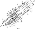
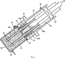
Фиг.1 - схематический вид примера крепежного устройства несущего троса на первом этапе впрыска;Figure 1 is a schematic view of an example of a mounting device of a carrier cable in the first injection stage;
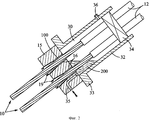
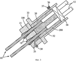
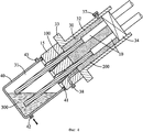
Фиг.2-4 - схематические виды крепежного устройства, показанного на Фиг.1, соответствующие другим этапам способа установки; иFigure 2-4 - schematic views of the mounting device shown in Figure 1, corresponding to other stages of the installation method; and
Фиг.5 - схематический вид другого варианта осуществления крепежного устройства.5 is a schematic view of another embodiment of a mounting device.
Описание вариантов осуществления изобретенияDescription of Embodiments
Несущий трос, показанный на Фиг.1, содержит множество прядей 10, каждая из который состоит из металлической стренги 11, помещенной в индивидуальный пластмассовый кожух 12. Для упрощения на фигурах показаны только две пряди 10. Обычно применяется большее число прядей, например, несколько десятков прядей. Пряди 20 проходят параллельно одна другой вдоль заданной траектории несущего троса, например, вдоль наклонной линии вантового троса между полотном и пилоном моста или вдоль траектории предварительного напряжения троса.The carrier cable shown in FIG. 1 contains a plurality of
Несущий трос закрепляется на обоих концах. Крепежные устройства передают усилие натяжения троса на конструкцию.The carrier cable is fixed at both ends. Fasteners transmit the pulling force of the cable to the structure.
Для надежного зажатия прядей 10 в крепежных устройства производят удаление пластмассовых кожухов 12 на концах прядей 10, вследствие чего металл стренга 11 оголяется. На каждом конце троса оголенные участки прядей 10 проходят сквозь крепежный блок 15 крепежного устройства. Крепежный блок 15 имеет несколько каналов 16, проходящих между задней стороной 17 (в сторону рабочей части троса, где пряди находятся в натянутом состоянии) и передней стороной 18. Каждая прядь 10 вставляется в один из каналов 16 с фиксирующим элементом 19.To securely clamp the
В проиллюстрированном варианте осуществления изобретения каждый канал 16, предназначенный для приема пряди 10, имеет цилиндрическую часть около задней стороны 17 крепежного блока 15, диаметр которой несколько больше диаметра стренги 11, и коническую часть, которая скошена в сторону передней стороны 18 крепежного блока 15. Блокирующий элемент выполнен в форме конического зажима 19, помещенного в конической части канала 16 для захвата металлической пряди 11. Зажим 19 имеет цилиндрическое отверстие для приема пряди и состоит из множества секторов (например, трех секторов), скрепленных кольцом 20, вставленным в кольцевую канавку, расположенную рядом с широким торцом зажима 19.In the illustrated embodiment, each
При установке троса его пряди 10 вставляются в соответствующие каналы 16 с коническими зажимами 19, создается усилие натяжения путем захвата частей прядей 11, выступающих из передней грани 18 крепежного блока 15, их натяжения при помощи привода, такого как гидравлический домкрат, и проталкивания зажимов 19 в каналы 16. После отключения привода зажимы 19 фиксируют пряди 11 в их каналах 16. Данная операция натяжения может выполняться последовательно по прядям, по группам прядей или сразу для всего троса.When installing the cable, its
После натяжения троса в каналах 16 остаются некоторые зазоры, в частности, вокруг прядей 11 в цилиндрических частях каналов и между секторами зажима в конических частях канала.After tensioning the cable, some gaps remain in the
Первый этап впрыска выполняется для обеспечения заполнения данных зазоров веществом 100, которое будет защищать металл от коррозии.The first injection step is performed to ensure that these gaps are filled with a
В одном варианте осуществления изобретения вещество, которым заполняются каналы 16 на первом этапе впрыска, является воском или консистентной смазкой. Однако оно может представлять собой отверждаемый материал, такой как полимер или смола.In one embodiment of the invention, the substance with which the
Как показано на Фиг.1, первый этап впрыска может выполняться для каждого канала 16 с использованием крышки 25 в форме чашки, установленной над входным отверстием канала. Крышка 25 плотно прилегает к передней стороне 18 крепежного блока 15 за счет уплотнения 26, а на противоположном ее торце имеется отверстие, через которое может пропускаться стренга 11. Уплотняющее кольцо 27 располагается по периметру стренги 11 для уплотнения переднего торца крышки 25, который фиксируется в своем положении при помощи кольца 28, обжимающего свободный конец стренги 11.As shown in FIG. 1, a first injection step may be performed for each
Защитный материал 100 впрыскивается в текучей или мягкой фазе через входное отверстие 29, имеющееся в крышке 25. Поскольку объем зазоров, не занятых металлической стренгой и зажимом, точно известен, в каждый канал 16 возможна подача заданного количества защитного материала, обеспечивающего заполнение канала целиком. Впрыскивающий насос (не показанный на фигурах) управляется таким образом, чтобы обеспечить впрыск заданного количества защитного материала 100 внутрь крышки 25 для того, чтобы целиком заполнить канал 16.The
Крепление чашеобразной крышки 25 к стренге 11 обеспечивает удержание крышки 25 около входного отверстия канала 16 в процессе впрыска защитного материала под давлением, необходимым для компенсации потери напора внутри канала 16. Следует заметить, что для удержания крышки на данном этапе могут применяться другие механизмы, например, прикрепленные к крепежному блоку 15.The fastening of the cup-shaped
После того как заполняющий материал 100, впрыскиваемый в каналы 16, отверждается (если он является полимером или смолой) или застывает за счет охлаждения (если он представляет собой воск), крышка 25 удаляется с передней стороны крепежного блока 15. Если наполнитель 100 является плотным материалом, таким как консистентная смазка, он не требует времени на отверждение, и крышка может удаляться сразу после впрыска. На участке стренги 1, который находился внутри крышки 25, может остаться некоторое количество защитного материала 10, или он может отсутствовать.After the filling
После первого этапа впрыска, осуществляется второй этап впрыска для заполнения прочего замкнутого объема (прочих замкнутых объемов) крепежного узла защитным материалом. В варианте осуществления изобретения, показанном на Фиг.1-4, имеются две камеры, требующие заполнения, камера 30 на задней стороне крепежного блока 15 и камера 31 на задней стороне. Эти две камеры 30, 31 заполняют защитным материалом 200, 300 по отдельности.After the first injection stage, the second injection stage is carried out to fill the other enclosed volume (other enclosed volumes) of the fastening assembly with protective material. In the embodiment of the invention shown in FIGS. 1-4, there are two chambers requiring filling, a
Первая камера 30 на задней стороне 17 крепежного блока ограничена в радиальном направлении трубкой 32, через которую проходят натянутые участки прядей 10. Концы пластмассовых кожухов 12 прядей расположены внутри камеры 30. Напротив крепежного блока 15 камера 30 закрывается уплотняющим устройством 34, например, сальниковым приспособлением, описанным в документе WO 01/20098 A1, которое изолирует камеру 30 снаружи, обеспечивая при этом прохождение прядей 10.The
В данном примере передний конец трубки 32 снабжен фланцем 33, который образует опорную поверхность для крепежного блока 15, при этом фланец 33 упирается в конструкцию, оборудованную тросом. Предполагается, что крепежный узел может иметь различные другие схемы компоновки в пределах объема настоящего изобретения.In this example, the front end of the
Впрыск защитного материала 200 в первую камеру (см. Фиг.2) производится через вход, который в проиллюстрированном примере сформирован каналом 35, выполненным в крепежном блоке 15 в нижней части камеры 30. В показанной конструкции канал 35 имеет изгиб для обеспечения доступа к нему с боковой стороны крепежного блока 15. Он также может быть прямолинейным и выходить на переднюю сторону 18 крепежного блока 15. Для выпуска воздуха, содержащегося в камере 30, на этапе впрыска в верхней части трубки 32 сформирована отдушина 36. После завершения впрыска отдушина 36 закрывается пробкой 37 (см. Фиг.3), при необходимости защитному материалу 200 дается время на отверждение или застывание, после чего производится закупоривание входного канала 35 другой пробкой 38.The
Вторая камера 31 на передней стороне 18 крепежного блока ограничена кожухом 40, показанным на Фиг.4. Кожух 40 установлен на крепежном блоке 15 при помощи болтов или других крепежных средств (не показанных на фигуре). Уплотнительное кольцо 41 установлено между задним торцом кожуха 40 и передней гранью 18 крепежного блока для предотвращения вытекания защитного материала в процессе впрыска. Размеры кожуха 40 обеспечивают размещение в нем оголенных концов всех прядей 10 троса. В его нижней части имеется канал 42 для впрыска защитного материала 300, а в его верхней части имеется отдушина 43 для выпуска воздуха при впрыске защитного материала 300.The
Защитный материал 300, впрыскиваемый во вторую камеру 31, заполняет все остающиеся пустоты. При вытекании материала через отдушину 43 впрыск прекращают, и в отдушину 43 устанавливают пробку 45. При необходимости защитному материалу 300 дается время на отверждение или застывание, после чего производится закупоривание входного канала 42 другой пробкой 38.The
Защитный материал, впрыскиваемый для заполнения каналов 16, камеры 30 в задней части крепежного блока 15 и камеры 31 в передней части крепежного блока 15, может подбираться независимо для каждого заполняемого объема, что позволяет оптимизировать крепежный узел путем подбора в каждом случае материала с требуемыми характеристиками.The protective material injected to fill the
Камера 31, расположенная в передней части крепежного бока 15, может открываться путем удаления кожуха 40 в процессе всего периода службы крепежного узла для обеспечения проверки правильности его функционирования. Из этих соображений обычно желательным является применение в данной камере 31 защитного материала 300, который может быть легко удален. Воск является предпочтительным материалом для данной цели, поскольку он может быть расплавлен или, по меньшей мере, размягчен за счет нагрева и откачан при помощи насоса. Также возможно применение консистентной смазки.The
Захват и закрепление прядей 10 происходит в каналах 16. Упругий материал 100, обладающий смазывающими свойствами, такой как консистентная смазка или воск пригоден с точки зрения его хороших усталостных свойств, за счет чего повышается суммарная прочность прядей.The capture and fixing of the
В камеру 30 в задней части крепежного блока 15 возможно проникновение воды, стекающей по конструкции или по тросу. Применение гибкого, вязкого и связанного материала 200 часто является наилучшим способом предотвращения подобного проникновения. Предпочтительным является выпрыск в данную часть крепежного узла полимера или смолы.Into the
На Фиг.5 показан альтернативный вариант осуществления крепежного устройства, для которого второй этап впрыска, т.е. этап, выполняемый после заполнения каналов 16, в которых зафиксированы пряди, по существу производится за один шаг. Заполняемая таким образом камера состоит из двух частей 50, 51, соединенных при помощи одного или большего числа соединительных каналов 52. Первая часть 50 расположена на задней стороне 17 крепежного блока 15, выполняет функции, аналогичные функциям первой камеры 30 варианта осуществления изобретения, показанного на Фиг.1-4, и ограничена цилиндрической трубкой 32 и сальниковым уплотняющим устройством 34. Вторая часть 51 расположена на передней стороне 18 крепежного блока 15, выполняет функции, аналогичные функциям второй камеры 31 варианта осуществления изобретения, показанного на Фиг.1-4, и ограничена кожухом 40. Соединительные каналы 52 параллельны каналам, содержащим пряди.5 shows an alternative embodiment of a fastening device for which a second injection step, i.e. the step after filling the
После установки и натяжения прядей 10 выполняется первый этап впрыска для заполнения каналов 16 защитным веществом 100, как описано со ссылками на Фиг.1. Затем на крепежный блок 15 устанавливают кожух 40 и выполняют второй этап впрыска для ввода защитного материала 400 в состоящую из двух частей камеру 50-51.After installation and tension of the
В варианте, показанном на Фиг.5, например, представляет собой крепежный узел нижнего конца наклонного вантового троса. В данной конфигурации нижняя часть крепежного узла находится в нижней части кожуха, в которой выполнен вход 42. Как и в предыдущем варианте осуществления изобретения, имеются две отдушины 36, 43, одна (36) в верхней части задней части 50 камеры, а другая (43) в верхней части передней части 51 камеры. На втором этапе впрыска поднимается уровень текучего материала 400. При достижении отдушины 42 происходит вытекание материала и отдушину 43 закрывают пробкой 45 для продолжения впрыска и обеспечения дальнейшего повышения уровня защитного материала 400 в соединительных каналах 52 и в задней части 50 камеры. При достижении другой отдушины 36 второй этап впрыска прекращают, и отдушину 36 закрывают пробкой. При необходимости защитному материалу 400 дается время на отверждение или застывание, после чего производится закупоривание входного канала 42 другой пробкой.In the embodiment shown in FIG. 5, for example, it is a fastener assembly of the lower end of an inclined cable-stayed cable. In this configuration, the lower part of the mounting unit is located in the lower part of the casing in which the
В варианте осуществления изобретения, показанном на Фиг.5, защитный материал 400, подаваемый под давлением в камеру 50-51 на втором этапе, предпочтительно, хотя необязательно, является таким же материалом, что и защитный материал 100, подаваемый под давлением в каналы 16 на первом этапе. Например, воск или консистентная смазка может впрыскиваться в каналы 16, а затем в состоящую из двух частей камеру 50-51. Однако в соответствии с требованиями конкретной конструкции предпочтительным может оказаться применение различных заполняющих материалов.In the embodiment of the invention shown in FIG. 5, the
В еще одном варианте осуществления изобретения камера, заполняемая на втором этапе впрыска, расположена только на передней стороне крепежного блока 15. Концевые участки пластмассовых кожухов 12 прядей 10 в этом случае располагаются внутри каналов 16 крепежного блока 15 или в индивидуальных продолжениях данных каналов, выходящих за пределы крепежного блока 15.In yet another embodiment of the invention, the chamber to be filled in the second injection stage is located only on the front side of the mounting
В этом случае первый этап впрыска выполняется для заполнения каналов 16 и/или их продолжения защитным материалом 100. Производится заполнение, по меньшей мере, участков каналов 16 и/или их продолжений, в которых на металле стренги отсутствует пластмассовый кожух. Независимый впрыск защитного материала в каналы 16 и/или их продолжения обеспечивает надежное заполнение вне зависимости от переменных потерь напора, обычно имеющих место при впрыске вещества в данные каналы.In this case, the first injection step is performed to fill the
После этого выполняют второй этап впрыска для ввода защитного материала 300, который предпочтительно отличается от ранее введенного защитного материала 100, в камеру 31, расположенную только на передней стороне 18 крепежного блока 15 и содержащую концевые участки стренг 11. Он может осуществляться так же, как и этап, описанный со ссылками на Фиг.4.After that, the second injection stage is performed to enter the
В том случае, когда камера 31, заполняемая защитным материалом, расположена только на передней стороне крепежного блока 15, подходящим вариантом защитного материала часто может оказаться применение воска или консистентной смазки, как для каналов 16, так и для камеры 31, поскольку эти материалы обеспечивают хорошие усталостные характеристики (для каналов 16) и поскольку они могут быть относительно просто удалены (из камеры 31). Однако в качестве подходящих или предпочтительных могут применяться и другие материалы. Например, в крепежном узле данной конструкции может потребоваться обеспечение водонепроницаемости задней части каналов. Из этих соображений в каналах 16 возможно применение защитного заполняющего материала, такого как полимер или смола, а в камеру 31 может вводиться воск или консистентная смазка.In the case where the
Вышеописанный способ защиты оголенных концов прядей несущего троса при помощи двух или большего числа этапов впрыска материала в различные части крепежного устройства применим при установке нового троса. Он также может применяться при обслуживании или ремонте уже существующего троса. В этом случае защитный заполняющий материал, который был предварительно установлен в различных частях крепежного устройства, может удаляться (например, при помощи способа, описанного в заявке на патент Франции No. 1152557 от 28 марта 2011 г.) перед впрыском одного или большего числа защитных материалов за два или большее число этапов, как описано выше.The above method of protecting the exposed ends of the strands of the carrier cable using two or more stages of material injection into various parts of the mounting device is applicable when installing a new cable. It can also be used when servicing or repairing an existing cable. In this case, the protective filling material that has been pre-installed in various parts of the mounting device can be removed (for example, using the method described in French Patent Application No. 1152557 of March 28, 2011) before the injection of one or more protective materials in two or more stages, as described above.
Хотя выше было приведено подробное описание примеров осуществления изобретения, специалистам в данной области техники понятны конструкции различных альтернативных вариантов, модификаций и эквивалентов.Although the detailed description of exemplary embodiments of the invention has been given above, those skilled in the art will understand the designs of various alternatives, modifications, and equivalents.
В частности, предполагается, что вышеупомянутые варианты защитных материалов, которыми заполняются различные части крепежного узла, являются предметом оптимизации конструкции и могут заменяться в зависимости от требуемой функциональности для конкретной конструкции крепежного узла, имеющей конкретную геометрическую конфигурацию или расположение.In particular, it is contemplated that the aforementioned variants of protective materials that fill the various parts of the fastener assembly are subject to structural optimization and may be replaced depending on the required functionality for a particular fastener assembly design having a particular geometric configuration or arrangement.
Также предполагается, что вышеописанный способ установки с использованием нескольких этапов впрыска для заполнения сначала каналов 16, содержащих пряди, а затем одной или большего числа камер на одной или обеих сторонах крепежного блока 5, обеспечивает преимущество, заключающееся в обеспечении надлежащего заполнения и защиты металлических прядей даже в случаях применения одинакового защитного вещества во всех частях крепежного узла.It is also contemplated that the above-described installation method using several injection steps to first fill the
Claims (15)
- выполнение первого этапа впрыска защитного материала (100), по меньшей мере, в некоторые каналы (16) крепежного блока;
- формирование камеры (31; 50-51), по меньшей мере, на передней стороне крепежного блока так, что концевые участки множества прядей троса содержатся в камере; и
- выполнение второго этапа впрыска защитного материала (300; 400) в указанную камеру, за счет чего защитный материал, впрыскиваемый на втором этапе, контактирует с концевыми участками прядей.1. A method of protecting the end of a cable, consisting of a plurality of parallel strands (10) and secured with a mounting block (15) having a front side (18), a rear side (17) and channels (16, 52) passing between the front and rear sides, while each strand of the cable is held in the corresponding channel by a locking element (19), containing the following steps:
- performing the first injection stage of the protective material (100) into at least some of the channels (16) of the mounting block;
- the formation of the camera (31; 50-51), at least on the front side of the mounting block so that the end sections of the many strands of the cable are contained in the camera; and
- performing the second stage of injection of the protective material (300; 400) into the specified chamber, due to which the protective material injected in the second stage is in contact with the end sections of the strands.
- установку на вход канала чашеобразной крышки (25) с герметичным прилеганием;
- впрыск защитного материала (100) внутрь чашеобразной крышки для подачи материала в канал и
- удаление чашеобразной крышки.3. The method according to claim 1, characterized in that the first stage of injection into each channel (16) contains:
- installation at the entrance to the channel of the cup-shaped cover (25) with a tight fit;
- injection of the protective material (100) into the bowl-shaped lid for feeding material into the channel and
- removal of a cup-shaped lid.
Applications Claiming Priority (1)
| Application Number | Priority Date | Filing Date | Title |
|---|---|---|---|
| PCT/IB2011/001046 WO2012140462A1 (en) | 2011-04-15 | 2011-04-15 | Method of protecting the end of a multi-tendon cable |
Publications (2)
| Publication Number | Publication Date |
|---|---|
| RU2013150822A RU2013150822A (en) | 2015-05-20 |
| RU2566541C2 true RU2566541C2 (en) | 2015-10-27 |
Family
ID=44628235
Family Applications (1)
| Application Number | Title | Priority Date | Filing Date |
|---|---|---|---|
| RU2013150822/03A RU2566541C2 (en) | 2011-04-15 | 2011-04-15 | Protection of multistrand rope ends |
Country Status (12)
| Country | Link |
|---|---|
| US (1) | US9446541B2 (en) |
| EP (1) | EP2697447B1 (en) |
| KR (3) | KR20190097322A (en) |
| AU (1) | AU2011365314B2 (en) |
| DK (1) | DK2697447T3 (en) |
| ES (1) | ES2572636T3 (en) |
| HK (1) | HK1189395A1 (en) |
| HU (1) | HUE029019T2 (en) |
| MX (1) | MX339730B (en) |
| PL (1) | PL2697447T3 (en) |
| RU (1) | RU2566541C2 (en) |
| WO (1) | WO2012140462A1 (en) |
Families Citing this family (4)
| Publication number | Priority date | Publication date | Assignee | Title |
|---|---|---|---|---|
| DE102013215136A1 (en) * | 2013-08-01 | 2015-02-05 | Dywidag-Systems International Gmbh | Corrosion-protected tension member and plastically deformable disc made of anti-corrosion material for such a tension member |
| IT201800005437A1 (en) * | 2018-05-16 | 2019-11-16 | FIXING DEVICE FOR TIE ROPES | |
| CN109098086A (en) * | 2018-10-22 | 2018-12-28 | 湖南路桥建设集团有限责任公司 | A kind of anticorrosion structure and method of suspension cable anchor head steel strand wires |
| JP6807482B1 (en) * | 2020-08-18 | 2021-01-06 | 中日本ハイウェイ・エンジニアリング東京株式会社 | Tendon's head fixation structure |
Citations (4)
| Publication number | Priority date | Publication date | Assignee | Title |
|---|---|---|---|---|
| GB2155973A (en) * | 1984-03-23 | 1985-10-02 | Acero Y Caucho Sa Manufacturas | Stressed reinforcing tendon |
| EP0323285A1 (en) * | 1987-11-25 | 1989-07-05 | Freyssinet International (Stup) | Stay cables and their anchorage |
| RU2131010C1 (en) * | 1997-12-30 | 1999-05-27 | Государственный научно-исследовательский, проектно-конструкторский и изыскательский институт "Атомэнергопроект" | Prestressed ferroconcrete constructions |
| FR2822177A1 (en) * | 2001-03-15 | 2002-09-20 | Freyssinet Int Stup | Anchoring system for pre-stressed reinforcing cables comprises block with holes for cables running in opposite directions and thrust surface for structure |
Family Cites Families (22)
| Publication number | Priority date | Publication date | Assignee | Title |
|---|---|---|---|---|
| FR1152557A (en) | 1954-09-21 | 1958-02-20 | Device for automatic lifting of blades for shedding in table looms and at home | |
| BE794024A (en) * | 1972-01-21 | 1973-05-02 | Brandestini Antonio | ANCHORING DEVICE FOR CABLES COMPOSED OF STRANDS |
| FR2492870A1 (en) | 1980-10-27 | 1982-04-30 | Precontrainte Structures Ste F | Anchor for cable in concrete - has perforated plate sandwiched between sealing cap and steel support plate |
| DE3224702C2 (en) | 1982-07-02 | 1986-01-16 | Dyckerhoff & Widmann AG, 8000 München | Device for anchoring and coupling a bundle tendon for prestressed concrete |
| JPS59173712U (en) * | 1983-05-09 | 1984-11-20 | 株式会社 春本鐵工所 | Bridge cable anchor socket |
| DE3339058A1 (en) | 1983-10-28 | 1985-05-15 | Dyckerhoff & Widmann AG, 8000 München | Exposed tightenable tension member comprising one or more tension elements, such as steel rods, wires or strands |
| DE3644551C2 (en) | 1986-12-24 | 1994-12-08 | Zueblin Ag | Anchoring for a composite tendon |
| CH676617A5 (en) | 1987-03-13 | 1991-02-15 | Dyckerhoff & Widmann Ag | |
| DE3801451C2 (en) | 1987-10-15 | 1994-09-29 | Dyckerhoff & Widmann Ag | Corrosion-protected free tension member, primarily tendon for prestressed concrete without bond |
| DE4118897A1 (en) * | 1991-06-08 | 1992-12-10 | Hochtief Ag Hoch Tiefbauten | Building component anchor system e.g. for strands in concrete block, etc. - has shrouding tube around anchor cables with sepg. and lubricating coating, giving easy exchange of clamp |
| US5173982A (en) | 1991-07-25 | 1992-12-29 | Greiner Inc, Southern | Corrosion protection system |
| DE4433832A1 (en) | 1994-09-22 | 1996-03-28 | Dyckerhoff & Widmann Ag | Corrosion-protected tension member, primarily tendon for prestressed concrete without bond |
| DE29504739U1 (en) * | 1995-03-20 | 1995-05-18 | Dyckerhoff & Widmann Ag | Corrosion-protected tension member, primarily external tendon for prestressed concrete without bond |
| DE19733822A1 (en) | 1997-08-05 | 1999-02-11 | Dyckerhoff & Widmann Ag | Method for installing and tensioning a freely tensioned tension member and device for carrying out the method |
| FR2798410B1 (en) | 1999-09-15 | 2001-11-23 | Freyssinet Int Stup | ANCHORING DEVICE FOR ATTACHING A STRUCTURAL CABLE TO A CONSTRUCTION ELEMENT |
| FR2817566B1 (en) | 2000-12-04 | 2003-02-07 | Freyssinet Int Stup | INDIVIDUALLY PROTECTED CORD, USE THEREOF IN CONSTRUCTION, AND MANUFACTURING METHOD |
| ATE397701T1 (en) | 2001-01-29 | 2008-06-15 | Vsl Int Ag | DEVICE AND METHOD FOR ANCHORING A STAYED CABLE END TO A BASE |
| JP2003286759A (en) * | 2002-03-28 | 2003-10-10 | Ps Mitsubishi Construction Co Ltd | Pc anchorage device and method |
| JP2004052539A (en) * | 2002-05-30 | 2004-02-19 | Anderson Technology Kk | Tension end structure of prestressed concrete structure, and construction method for tension end |
| DE20311950U1 (en) * | 2003-08-02 | 2004-12-09 | Dywidag-Systems International Gmbh | Corrosion-protected tension member, in particular tendon for prestressed concrete |
| JP4387380B2 (en) * | 2006-06-15 | 2009-12-16 | 弘和産業株式会社 | Anchor repair method, anchor head and head back mechanism |
| MX337768B (en) * | 2011-04-15 | 2016-03-16 | Soletanche Freyssinet | Anchoring device for a multi-tendon cable. |
-
2011
- 2011-04-15 EP EP11730736.3A patent/EP2697447B1/en active Active
- 2011-04-15 KR KR1020197023770A patent/KR20190097322A/en not_active Application Discontinuation
- 2011-04-15 HU HUE11730736A patent/HUE029019T2/en unknown
- 2011-04-15 PL PL11730736.3T patent/PL2697447T3/en unknown
- 2011-04-15 MX MX2013011988A patent/MX339730B/en active IP Right Grant
- 2011-04-15 AU AU2011365314A patent/AU2011365314B2/en active Active
- 2011-04-15 RU RU2013150822/03A patent/RU2566541C2/en active
- 2011-04-15 US US14/009,767 patent/US9446541B2/en active Active
- 2011-04-15 KR KR1020187018507A patent/KR102012838B1/en active IP Right Grant
- 2011-04-15 DK DK11730736.3T patent/DK2697447T3/en active
- 2011-04-15 WO PCT/IB2011/001046 patent/WO2012140462A1/en active Application Filing
- 2011-04-15 KR KR1020137029333A patent/KR20140022402A/en not_active Application Discontinuation
- 2011-04-15 ES ES11730736.3T patent/ES2572636T3/en active Active
-
2014
- 2014-03-10 HK HK14102398.8A patent/HK1189395A1/en unknown
Patent Citations (4)
| Publication number | Priority date | Publication date | Assignee | Title |
|---|---|---|---|---|
| GB2155973A (en) * | 1984-03-23 | 1985-10-02 | Acero Y Caucho Sa Manufacturas | Stressed reinforcing tendon |
| EP0323285A1 (en) * | 1987-11-25 | 1989-07-05 | Freyssinet International (Stup) | Stay cables and their anchorage |
| RU2131010C1 (en) * | 1997-12-30 | 1999-05-27 | Государственный научно-исследовательский, проектно-конструкторский и изыскательский институт "Атомэнергопроект" | Prestressed ferroconcrete constructions |
| FR2822177A1 (en) * | 2001-03-15 | 2002-09-20 | Freyssinet Int Stup | Anchoring system for pre-stressed reinforcing cables comprises block with holes for cables running in opposite directions and thrust surface for structure |
Also Published As
| Publication number | Publication date |
|---|---|
| DK2697447T3 (en) | 2016-05-30 |
| US20140021649A1 (en) | 2014-01-23 |
| KR20190097322A (en) | 2019-08-20 |
| ES2572636T3 (en) | 2016-06-01 |
| AU2011365314A1 (en) | 2013-10-24 |
| PL2697447T3 (en) | 2016-09-30 |
| AU2011365314B2 (en) | 2017-04-27 |
| KR20180077327A (en) | 2018-07-06 |
| EP2697447A1 (en) | 2014-02-19 |
| EP2697447B1 (en) | 2016-02-24 |
| RU2013150822A (en) | 2015-05-20 |
| KR20140022402A (en) | 2014-02-24 |
| US9446541B2 (en) | 2016-09-20 |
| HUE029019T2 (en) | 2017-02-28 |
| MX2013011988A (en) | 2013-11-20 |
| WO2012140462A1 (en) | 2012-10-18 |
| MX339730B (en) | 2016-06-06 |
| HK1189395A1 (en) | 2014-06-06 |
| KR102012838B1 (en) | 2019-08-21 |
Similar Documents
| Publication | Publication Date | Title |
|---|---|---|
| RU2566882C2 (en) | Multistrand rope fastener | |
| RU2566541C2 (en) | Protection of multistrand rope ends | |
| CN1035687C (en) | Environmental sealing | |
| US8006763B2 (en) | Method and system for installing subsea insulation | |
| JP4827266B2 (en) | Packer assembly for crack repair using elastic storage tube. | |
| RU2557027C2 (en) | Method and device for protection of tension wire end | |
| US7635007B2 (en) | Method of repairing a leak in a flange of a gas pipe | |
| KR20130038819A (en) | Sealing arrangement | |
| US20200199831A1 (en) | Improved assembly comprising a structural cable and a saddle | |
| KR102027925B1 (en) | Reinforcement method of bridge girder using coated strand tendon and anchoring device used therein | |
| CN101679017A (en) | Sump for fuel dispenser | |
| KR100976846B1 (en) | Packer structure and construction method using the same | |
| EP2357065A1 (en) | Impregnation plant for impregnating a liner with barrier layer | |
| KR102292311B1 (en) | Cable anchorage construction method for watertight device using double tube | |
| JP6049477B2 (en) | Cable tray water pressure resistant treatment method and water pressure resistant structure | |
| CN114000427B (en) | Cable sealing device adopting double-layer pipe shape | |
| JP3602124B1 (en) | Cable protection and fixing method | |
| CN110536855B (en) | Elevator strap joint end termination | |
| JPS6225060B2 (en) |