RU2560494C2 - Wheel turning lathe installed under workshop floor - Google Patents
Wheel turning lathe installed under workshop floor Download PDFInfo
- Publication number
- RU2560494C2 RU2560494C2 RU2012155860/02A RU2012155860A RU2560494C2 RU 2560494 C2 RU2560494 C2 RU 2560494C2 RU 2012155860/02 A RU2012155860/02 A RU 2012155860/02A RU 2012155860 A RU2012155860 A RU 2012155860A RU 2560494 C2 RU2560494 C2 RU 2560494C2
- Authority
- RU
- Russia
- Prior art keywords
- wheel
- gear
- rollers
- wheelset
- roller
- Prior art date
Links
Images
Classifications
-
- B—PERFORMING OPERATIONS; TRANSPORTING
- B23—MACHINE TOOLS; METAL-WORKING NOT OTHERWISE PROVIDED FOR
- B23B—TURNING; BORING
- B23B5/00—Turning-machines or devices specially adapted for particular work; Accessories specially adapted therefor
- B23B5/28—Turning-machines or devices specially adapted for particular work; Accessories specially adapted therefor for turning wheels or wheel sets or cranks thereon, i.e. wheel lathes
- B23B5/32—Turning-machines or devices specially adapted for particular work; Accessories specially adapted therefor for turning wheels or wheel sets or cranks thereon, i.e. wheel lathes for reconditioning wheel sets without removing same from the vehicle; Underfloor wheel lathes for railway vehicles
-
- B—PERFORMING OPERATIONS; TRANSPORTING
- B23—MACHINE TOOLS; METAL-WORKING NOT OTHERWISE PROVIDED FOR
- B23B—TURNING; BORING
- B23B25/00—Accessories or auxiliary equipment for turning-machines
-
- B—PERFORMING OPERATIONS; TRANSPORTING
- B23—MACHINE TOOLS; METAL-WORKING NOT OTHERWISE PROVIDED FOR
- B23B—TURNING; BORING
- B23B2260/00—Details of constructional elements
- B23B2260/096—Levers
-
- Y—GENERAL TAGGING OF NEW TECHNOLOGICAL DEVELOPMENTS; GENERAL TAGGING OF CROSS-SECTIONAL TECHNOLOGIES SPANNING OVER SEVERAL SECTIONS OF THE IPC; TECHNICAL SUBJECTS COVERED BY FORMER USPC CROSS-REFERENCE ART COLLECTIONS [XRACs] AND DIGESTS
- Y10—TECHNICAL SUBJECTS COVERED BY FORMER USPC
- Y10T—TECHNICAL SUBJECTS COVERED BY FORMER US CLASSIFICATION
- Y10T82/00—Turning
- Y10T82/18—Lathe for wheel or axle
- Y10T82/185—In situ lathe for railroad wheel
Abstract
Description
Изобретение относится к колесотокарному станку, расположенному под полом цеха, в соответствии с ограничительной частью основного пункта формулы изобретения. Точнее, изобретение относится к варианту осуществления подъемного приводного механизма ведущих роликов колесотокарного станка, расположенного под полом цеха, для колесной пары. Сравнимые варианты решений уже известны из документов DE 202007016469 и DE 202008009409.The invention relates to a wheeled machine located under the floor of the workshop, in accordance with the restrictive part of the main claim. More specifically, the invention relates to an embodiment of a hoisting drive mechanism of driving rollers of a wheel-turning machine located under the floor of the workshop for a wheelset. Comparable solutions are already known from documents DE 202007016469 and DE 202008009409.
В противоположность известным решениям задача предложенного на рассмотрение изобретения состоит в том, чтобы дополнительно уменьшить конструктивную высоту подъемного приводного механизма ведущих роликов и, в то же время, предложить более экономичное решение.In contrast to the known solutions, the objective of the invention proposed for consideration is to further reduce the structural height of the lifting drive mechanism of the drive rollers and, at the same time, to offer a more economical solution.
В соответствии с изобретением эта задача решается посредством того, что соединение с геометрическим замыканием между обоими, образующими пару роликов, ведущими роликами состоит из двух зубчатых штанг, которые входят в зацепление в общую шестерню, причем зубчатые штанги шарнирно соединены с каждым силовым цилиндром и промежуточным рычагом, и на, соответственно, противолежащей месту вхождения в зацепление с шестерней стороне поддерживаются посредством роликовой направляющей.In accordance with the invention, this problem is solved by the fact that the connection with a geometrical closure between the two leading pair of rollers, the drive rollers consists of two gear rods that mesh into the common gear, and the gear rods are pivotally connected to each power cylinder and the intermediate lever , and, respectively, at the opposite place of engagement with the gear side are supported by a roller guide.
Предпочтительные варианты осуществления данного решения следуют из зависимых пунктов 2-5 формулы изобретения.Preferred embodiments of this solution follow from dependent claims 2-5.
Изобретение описывается далее более детально на основании примера осуществления. Соответственно, в упрощенном изображении представлены на:The invention is further described in more detail based on an embodiment. Accordingly, in a simplified image are presented on:
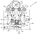
фиг.1 - вид спереди подъемного приводного механизма,figure 1 is a front view of a lifting drive mechanism,
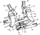
фиг.2 - подъемный приводной механизм с фиг.1, в перспективном изображении.figure 2 - lifting the drive mechanism of figure 1, in a perspective image.
Два ведущих ролика 1, Г (фиг.1 и 2) образуют, соответственно, пару роликов и установлены, соответственно, с возможностью вращения и приведения в действие на свободном конце 21, 21' коромысла 12, 12' обоймы ролика; в целом колесотокарный станок 27, расположенный под полом цеха, имеет две пары роликов. Коромысло 12, 12' обоймы ролика состоит, соответственно, из коромысла 13, 13' и первого качающегося рычага 4, 4'. Коромысло 13, 13' и первый качающийся рычаг 4, 4' на первом конце 14,14' первого качающегося рычага 4, 4' прочно соединены друг с другом. Оба коромысла 13, 13' расположены, соответственно, с возможностью поворота вокруг поворотной оси А или В, в станине 10 станка. Станина 10 станка упрощенно изображена на фиг.1 посредством контурной линии.Two driving rollers 1, G (FIGS. 1 and 2) form, respectively, a pair of rollers and are mounted, respectively, with the possibility of rotation and actuation on the
Поворотные оси А, В с радиальным зазором 24 проходят параллельно оси Z вращения колесной пары 22, причем колесная пара 22 должна представлять собой заготовку с максимально большим диаметром 8 колеса 7, которая может быть обработана на колесотокарном станке 27, расположенном под полом цеха. Соответственно различным диаметрам 8 колес 7 колесной пары 22 положение коромысла 13, 13' для обработки больших диаметров колес выбирается практически горизонтальным, в то время как для обработки малых диаметров колес оно может принимать слегка отклоненное от вертикали положение.The rotary axes A, B with a
Оба свободных вторых конца 15, 15' качающегося рычага 4, 4', соответственно, шарнирно соединены с практически горизонтальным подъемным цилиндром 25, 25' через первые шарниры 18, 18', вторые шарниры 19, 19' и третьи шарниры 20, 20'. На шарниры 18, 18' и 19, 19', к тому же, соответственно, шарнирно воздействует промежуточный рычаг 16, 16'.The two free
Посредством шарниров 19, 19' промежуточные рычаги 16, 16', соответственно, шарнирно соединены с зубчатой штангой 17, 17'. Соответственно, на другом конце зубчатых штанг 17, 17' на них шарнирно воздействуют силовые цилиндры 25, 25'. Посредством крепежных элементов 3, 3' силовые цилиндры 25, 25', со своей стороны, соответственно, шарнирным образом закреплены на станине 10 станка.By means of
Обе зубчатые штанги 17, 17' на противолежащих друг другу сторонах с геометрическим замыканием входят в зацепление в шестерню 23, которая также с возможностью вращения установлена в станине 10 станка. Вхождение в зацепление обеих зубчатых штанг 17, 17' в шестерню 23 гарантируется, соответственно, наличием роликовых направляющих 26, 26', чтобы зубчатые штанги 17, 17' во время вхождения в зацепление с шестерней 23 не могли выйти из зацепления. Роликовые направляющие 26, 26' также закреплены в станине 10 станка.Both
Чтобы ведущие ролики 1, 1' с силовым замыканием постоянно прилегали к окружности 6 катания колес 7 колесной пары 22 и могли следовать всем неровностям или неравномерностям окружности 6 катания, между качающимися рычагами 4, 4' и промежуточными рычагами 16, 16' установлен, соответственно, упругий элемент в форме нажимной пружины 2, 2'. В предложенном на рассмотрение примере нажимные пружины 2, 2' находятся, соответственно, вблизи шарниров 18, 18', через которые качающиеся рычаги 4, 4' шарнирно соединены с промежуточными рычагами 16, 16'.So that the drive rollers 1, 1 'with a power circuit are constantly adjacent to the
Вследствие практически горизонтального расположения обоих силовых цилиндров 25, 25' и тем самым обеих зубчатых штанг 17, 17', получают особенно низкую по вертикали конструкцию для подъемного приводного механизма ведущих роликов 1, 1'. Ввиду варианта осуществления промежуточных рычагов 16, 16' в виде двуплечей конструкции 9, особенно хорошо различимой на фиг.2, вдоль оси Z вращения колесной пары 22 имеется также небольшая в глубину 11 конструктивная высота. Хорошая доступность и облегченная регулируемость нажимных пружин 2, 2' за счет предложенной конструкции также гарантированы.Due to the almost horizontal arrangement of both
Перечень ссылочных позицийList of Reference Items
Claims (5)
отличающийся тем, что соединение с геометрическим замыканием состоит из двух зубчатых штанг (17, 17'), которые входят в зацепление с общей шестерней (23), причем каждая зубчатая штанга (17, 17') шарнирно соединена с силовым цилиндром (25, 25') и промежуточным рычагом (16, 16'), и на, соответственно, противолежащей месту вхождения в зацепление с шестерней (23) стороне поддерживаются роликовой направляющей (26, 26').1. Wheel-turning machine (27), located under the floor of the workshop, for processing wheel profiles (7) and brake disks of wheel sets (22) for trains with metal cutting tools, in which the wheel set (22) is mounted in axle boxes for rotation around its axis of rotation (Z), containing clamping elements for acting on axle boxes of a wheelset (22), of which, respectively, one is provided on each end side of its bed (10), with two drive rollers (1, 1 '), which form respectively a pair of rollers for each of the two wheels (7) of the wheelset (22) for raising, actuating and lowering the wheelset (22) before, during or after processing, each drive roller (1, 1 ') being rotatable and the actuator is mounted on the free end (21, 21 ') of the rocker arm (12, 12') of the clip of the roller, which is formed from the housing (13, 13 ') of the rocker arm and swing arm (4, 4'), which are on the first end (14 , 14 ') of the swing arm (4, 4') are firmly connected to each other, while the rocker arm (12, 12 ') of the roller cage is installed in the machine bed with the possibility of rotation around the pivot axis (A, B), which passes with a radial clearance (24) and parallel to the axis (Z) of rotation of the wheelset (22), and the free second end (15, 15 ') of the swing arm (4, 4') at least one intermediate lever (16, 16 ') and hinges (18, 18'; 19, 19 '; 20, 20 ′) is geometrically connected to another drive roller (1, 1 ′) of a pair of rollers,
characterized in that the connection with a geometric closure consists of two gear rods (17, 17 '), which are engaged with a common gear (23), each gear rod (17, 17') pivotally connected to the power cylinder (25, 25 ') and the intermediate lever (16, 16'), and on the opposite opposite point of engagement with the gear (23) side are supported by a roller guide (26, 26 ').
Applications Claiming Priority (3)
| Application Number | Priority Date | Filing Date | Title |
|---|---|---|---|
| DE202010007239.5 | 2010-05-24 | ||
| DE201020007239 DE202010007239U1 (en) | 2010-05-24 | 2010-05-24 | underfloor wheel lathe |
| PCT/DE2011/001092 WO2011147406A2 (en) | 2010-05-24 | 2011-05-20 | Under-floor wheelset lathe |
Publications (2)
| Publication Number | Publication Date |
|---|---|
| RU2012155860A RU2012155860A (en) | 2014-06-27 |
| RU2560494C2 true RU2560494C2 (en) | 2015-08-20 |
Family
ID=42751346
Family Applications (1)
| Application Number | Title | Priority Date | Filing Date |
|---|---|---|---|
| RU2012155860/02A RU2560494C2 (en) | 2010-05-24 | 2011-05-20 | Wheel turning lathe installed under workshop floor |
Country Status (10)
| Country | Link |
|---|---|
| US (1) | US9138809B2 (en) |
| EP (1) | EP2576106A2 (en) |
| JP (1) | JP5832528B2 (en) |
| KR (1) | KR20130115103A (en) |
| CN (1) | CN103140314B (en) |
| AU (1) | AU2011257660A1 (en) |
| BR (1) | BR112012029960A2 (en) |
| DE (2) | DE202010007239U1 (en) |
| RU (1) | RU2560494C2 (en) |
| WO (1) | WO2011147406A2 (en) |
Families Citing this family (9)
| Publication number | Priority date | Publication date | Assignee | Title |
|---|---|---|---|---|
| US11426800B2 (en) | 2008-07-10 | 2022-08-30 | Hjr Real Estate Management, Llc | Portable profiler for locomotive or railcar wheels |
| US9358650B2 (en) | 2008-07-10 | 2016-06-07 | Hjr Equipment Rental, Inc. | System for and method of re-profiling locomotive and rail car wheels |
| US10226824B2 (en) * | 2008-07-10 | 2019-03-12 | Hjr Real Estate Management, Llc | Portable profiler for locomotive or railcar wheels |
| US11911833B2 (en) | 2010-09-20 | 2024-02-27 | Hjr Real Estate Management, Llc | System and method of re-profiling locomotive railcar wheels |
| PL3043937T3 (en) | 2013-09-09 | 2020-03-31 | Stadler Service Nederland B.V. | Mobile device for machining two wheels of a wheelset |
| DE202014007649U1 (en) * | 2014-09-18 | 2015-12-22 | Hegenscheidt Mfd Gmbh | underfloor wheel lathe |
| DE102017122023A1 (en) * | 2017-09-22 | 2019-03-28 | Hegenscheidt-Mfd Gmbh | Underfloor wheelset machine, in particular underfloor wheel lathe with adjustable track width |
| WO2019096971A1 (en) * | 2017-11-17 | 2019-05-23 | Hegenscheidt-Mfd Gmbh | Device and method for calibrating an underfloor wheelset lathe without a calibration wheelset |
| CN111496272A (en) * | 2020-05-03 | 2020-08-07 | 郑旭岳 | Metal part cutting device |
Citations (4)
| Publication number | Priority date | Publication date | Assignee | Title |
|---|---|---|---|---|
| RU2107586C1 (en) * | 1996-03-04 | 1998-03-27 | Акционерное общество "Рязанское специальное конструкторское бюро станкостроения" | Machine tool for turning of wheel pairs wheeling out for recovery of railway wheel tyre profile |
| RU51545U1 (en) * | 2005-10-26 | 2006-02-27 | Открытое акционерное общество "Станкон" | UNDERWHEEL WHEEL MACHINE |
| DE202007016469U1 (en) * | 2007-11-24 | 2008-03-13 | Hegenscheidt-Mfd Gmbh & Co. Kg | underfloor wheel lathe |
| RU82435U1 (en) * | 2008-11-24 | 2009-04-27 | Государственное образовательное учреждение высшего профессионального образования "Петербургский государственный университет путей сообщения" | MACHINE FOR TURNING WHEEL PAIRS WITHOUT DEMOUNTING THEM FROM THE ROLLING STOCK OF RAILWAY TRANSPORT |
Family Cites Families (12)
| Publication number | Priority date | Publication date | Assignee | Title |
|---|---|---|---|---|
| DE2937819C2 (en) * | 1979-09-19 | 1982-05-06 | Wilhelm Hegenscheidt, Gmbh, 5140 Erkelenz | Underfloor wheel set lathe |
| DD223380B1 (en) * | 1983-12-23 | 1988-11-16 | Buero F E Techn U Rational Der | STAND TO WORK ON THE WHEELS BUILT IN THE TURNING FRAME |
| JPS6261430U (en) * | 1985-10-04 | 1987-04-16 | ||
| FR2627716B1 (en) * | 1988-02-25 | 1994-07-01 | Nord Productique Sa | DEVICE FOR SETTING UP A RAIL VEHICLE ON A WHEEL REPROFILING LATHE |
| DE3809250C1 (en) * | 1988-03-18 | 1989-07-13 | Hoesch Maschinenfabrik Deutschland Ag, 4600 Dortmund, De | |
| DE3823832C1 (en) * | 1988-07-14 | 1989-03-09 | Hoesch Maschinenfabrik Deutschland Ag, 4600 Dortmund, De | |
| DE4006667A1 (en) * | 1990-03-03 | 1991-09-12 | Hoesch Maschinenfabrik Ag | UNDERFLOOR WHEEL SET LATHE FOR REPROFILING THE WHEELS OF RAILWAY WHEEL SETS |
| DE4320504A1 (en) * | 1993-06-21 | 1994-12-22 | Freimuth Ulrich | Floor-mounted lathe with friction-roller drive for machining wheel sets with or without axle bearings or axle boxes |
| DE4330811C2 (en) * | 1993-09-12 | 1995-08-31 | Niles Simmons Industrieanlagen | Wheelset alignment method for wheelset processing machines and wheelset alignment device |
| DE9414398U1 (en) * | 1994-09-06 | 1994-12-22 | Hoesch Maschinenfabrik Ag | Lathe for simultaneously re-profiling two wheels of a wheel set removed from a rail vehicle |
| EP0711618A1 (en) * | 1994-11-09 | 1996-05-15 | HEGENSCHEIDT-MFD GmbH | Process for machining a wheel-set and equipment for the application of that process |
| DE102005001220B4 (en) * | 2005-01-10 | 2007-12-13 | Hegenscheidt-Mfd Gmbh & Co. Kg | Underfloor wheel lathe for machining wheel sets for railway vehicles |
-
2010
- 2010-05-24 DE DE201020007239 patent/DE202010007239U1/en not_active Expired - Lifetime
-
2011
- 2011-05-20 CN CN201180026000.3A patent/CN103140314B/en not_active Expired - Fee Related
- 2011-05-20 AU AU2011257660A patent/AU2011257660A1/en not_active Abandoned
- 2011-05-20 RU RU2012155860/02A patent/RU2560494C2/en not_active IP Right Cessation
- 2011-05-20 WO PCT/DE2011/001092 patent/WO2011147406A2/en active Application Filing
- 2011-05-20 EP EP11767893.8A patent/EP2576106A2/en not_active Withdrawn
- 2011-05-20 US US13/703,280 patent/US9138809B2/en not_active Expired - Fee Related
- 2011-05-20 DE DE201111104052 patent/DE112011104052A5/en not_active Withdrawn
- 2011-05-20 KR KR20127033732A patent/KR20130115103A/en not_active Application Discontinuation
- 2011-05-20 BR BR112012029960A patent/BR112012029960A2/en not_active IP Right Cessation
- 2011-05-20 JP JP2013511535A patent/JP5832528B2/en not_active Expired - Fee Related
Patent Citations (4)
| Publication number | Priority date | Publication date | Assignee | Title |
|---|---|---|---|---|
| RU2107586C1 (en) * | 1996-03-04 | 1998-03-27 | Акционерное общество "Рязанское специальное конструкторское бюро станкостроения" | Machine tool for turning of wheel pairs wheeling out for recovery of railway wheel tyre profile |
| RU51545U1 (en) * | 2005-10-26 | 2006-02-27 | Открытое акционерное общество "Станкон" | UNDERWHEEL WHEEL MACHINE |
| DE202007016469U1 (en) * | 2007-11-24 | 2008-03-13 | Hegenscheidt-Mfd Gmbh & Co. Kg | underfloor wheel lathe |
| RU82435U1 (en) * | 2008-11-24 | 2009-04-27 | Государственное образовательное учреждение высшего профессионального образования "Петербургский государственный университет путей сообщения" | MACHINE FOR TURNING WHEEL PAIRS WITHOUT DEMOUNTING THEM FROM THE ROLLING STOCK OF RAILWAY TRANSPORT |
Also Published As
| Publication number | Publication date |
|---|---|
| RU2012155860A (en) | 2014-06-27 |
| BR112012029960A2 (en) | 2016-09-20 |
| AU2011257660A8 (en) | 2013-06-13 |
| WO2011147406A2 (en) | 2011-12-01 |
| AU2011257660A1 (en) | 2013-01-17 |
| JP2013526424A (en) | 2013-06-24 |
| US20130112052A1 (en) | 2013-05-09 |
| DE112011104052A5 (en) | 2013-10-02 |
| WO2011147406A3 (en) | 2012-02-23 |
| JP5832528B2 (en) | 2015-12-16 |
| CN103140314B (en) | 2015-06-03 |
| CN103140314A (en) | 2013-06-05 |
| US9138809B2 (en) | 2015-09-22 |
| DE202010007239U1 (en) | 2010-09-16 |
| KR20130115103A (en) | 2013-10-21 |
| EP2576106A2 (en) | 2013-04-10 |
Similar Documents
| Publication | Publication Date | Title |
|---|---|---|
| RU2560494C2 (en) | Wheel turning lathe installed under workshop floor | |
| CN100469471C (en) | Rough rolling vertical roller mill | |
| JP2013526424A5 (en) | ||
| WO2013149462A1 (en) | Avoidance-free three-dimensional parking space and movement driving mechanism for mobile case thereof | |
| CN102873573B (en) | The powerful five-axle linkage oscillating head mechanism of large power, electrically main shaft | |
| CN103500648A (en) | Coil winding machine for stereoscopic wound iron core transformer | |
| AU2008328358A1 (en) | Underfloor wheelset lathe | |
| CN203456281U (en) | Winding machine of three-dimensional wound-core transformer | |
| CN205330237U (en) | Embrace and press from both sides tire car carrier | |
| CN201434727Y (en) | Rapid wavelength scanning mechanism | |
| CN205628944U (en) | Oscillating steel pipe feeder | |
| CN208584124U (en) | A kind of welding robot walking mechanism | |
| CN105414866B (en) | Welding rolling wheel bracket with low noise and good supporting effect | |
| JP2012081550A5 (en) | ||
| CN205472534U (en) | Large -scale component upset machine | |
| CN215615995U (en) | Pre-welding device for processing I-shaped steel | |
| JP5337527B2 (en) | Vibration isolator for band saw machine | |
| CN102873606B (en) | Deburring device for guide rail | |
| CN105964713B (en) | Swing type steel pipe feeder | |
| CN204728782U (en) | Automobile carries vehicle frame and promotes traversing anti-shaking device | |
| CN202763609U (en) | Guide rail burring device | |
| CN210732780U (en) | Turnover device used in stone maintenance working process | |
| CN219401807U (en) | Three-roller plate bending machine | |
| CN102992187A (en) | Electric distance-fixing ladder-shaped plate blank buttress grippers | |
| CN114851316B (en) | Swinging self-adaptive adjusting clamping-shaft-free rotary cutter and working method thereof |
Legal Events
| Date | Code | Title | Description |
|---|---|---|---|
| MM4A | The patent is invalid due to non-payment of fees |
Effective date: 20160521 |