RU2558065C2 - Partially prefabricated building and method of its erection - Google Patents
Partially prefabricated building and method of its erection Download PDFInfo
- Publication number
- RU2558065C2 RU2558065C2 RU2013112930/03A RU2013112930A RU2558065C2 RU 2558065 C2 RU2558065 C2 RU 2558065C2 RU 2013112930/03 A RU2013112930/03 A RU 2013112930/03A RU 2013112930 A RU2013112930 A RU 2013112930A RU 2558065 C2 RU2558065 C2 RU 2558065C2
- Authority
- RU
- Russia
- Prior art keywords
- walls
- roof
- formwork
- floor
- beams
- Prior art date
Links
Images


Classifications
-
- E—FIXED CONSTRUCTIONS
- E04—BUILDING
- E04B—GENERAL BUILDING CONSTRUCTIONS; WALLS, e.g. PARTITIONS; ROOFS; FLOORS; CEILINGS; INSULATION OR OTHER PROTECTION OF BUILDINGS
- E04B1/00—Constructions in general; Structures which are not restricted either to walls, e.g. partitions, or floors or ceilings or roofs
- E04B1/35—Extraordinary methods of construction, e.g. lift-slab, jack-block
- E04B1/3533—Extraordinary methods of construction, e.g. lift-slab, jack-block characterised by the raising of hingedly-connected building elements, e.g. arches, portal frames
-
- E—FIXED CONSTRUCTIONS
- E04—BUILDING
- E04B—GENERAL BUILDING CONSTRUCTIONS; WALLS, e.g. PARTITIONS; ROOFS; FLOORS; CEILINGS; INSULATION OR OTHER PROTECTION OF BUILDINGS
- E04B1/00—Constructions in general; Structures which are not restricted either to walls, e.g. partitions, or floors or ceilings or roofs
- E04B1/35—Extraordinary methods of construction, e.g. lift-slab, jack-block
- E04B2001/3588—Extraordinary methods of construction, e.g. lift-slab, jack-block using special lifting or handling devices, e.g. gantries, overhead conveying rails
Landscapes
- Engineering & Computer Science (AREA)
- Architecture (AREA)
- Physics & Mathematics (AREA)
- Electromagnetism (AREA)
- Civil Engineering (AREA)
- Structural Engineering (AREA)
- Conveying And Assembling Of Building Elements In Situ (AREA)
Abstract
Description
Настоящее изобретение можно отнести к области техники строительных конструкций, конкретнее - к строительству зданий небольшого размера, таких как одноквартирные дома, небольшие склады или промышленные сооружения и цеха, начинающиеся со сборных бетонных плит. Задача изобретения относится к созданию частично сборного быстровозводимого здания и к способу его возведения.The present invention can be attributed to the field of construction technology, and more specifically to the construction of small buildings, such as single-family houses, small warehouses or industrial buildings and workshops, starting with precast concrete slabs. The objective of the invention relates to the creation of a partially prefabricated prefabricated building and to a method for its construction.
Патент изобретения P200600168 относится к системе строительства частично сборного здания. Система содержит пол, кровлю и наружные стены, все составленное из железобетонных плит, где наружные стены содержат оконные проемы и, где необходимо, дверные проемы.Patent P200600168 relates to a partially prefabricated building construction system. The system comprises a floor, a roof and external walls, all made up of reinforced concrete slabs, where the external walls contain window openings and, where necessary, doorways.
Патент P200600168 раскрывает возведение наружных стен и последующее возведение кровли. Наружные стены возводятся с помощью перемещения с поворотом с использованием подъемных элементов, содержащих фиксированнную часть, которая крепится к полу, и подвижную часть, перемещающуюся относительно фиксированной части и располагающуюся в оконных проемах наружных стен, подвижная часть крепится в проемах с помощью закрепляющих элементов. Затем подъемное средство также используется для подъема кровли, поскольку кровельная плита содержит множество проемов, совпадающих с местами установки подъемного средства, где подвижная часть подъемного средства крепится к проемам с помощью закрепляющих элементов.Patent P200600168 discloses the construction of external walls and the subsequent construction of a roof. The outer walls are erected by moving with rotation using lifting elements containing a fixed part, which is attached to the floor, and a moving part, moving relative to a fixed part and located in the window openings of the external walls, the moving part is fixed in the openings using fixing elements. Then, the lifting means is also used to lift the roof, since the roof plate contains many openings that coincide with the installation sites of the lifting means, where the movable part of the lifting means is attached to the openings using fixing elements.
Затем поднятые стены соединяются вместе с помощью двух металлических рам в форме квадрата, одна из рам располагается на внутренней поверхности каждой стены, а другая рама располагается на наружной поверхности, рамы скрепляются друг с другом и с соответствующими стенами, между которыми затем укладывается бетонная масса.Then the raised walls are joined together using two metal frames in the shape of a square, one of the frames is located on the inner surface of each wall, and the other frame is located on the outer surface, the frames are fastened to each other and to the corresponding walls, between which concrete mass is then laid.
Наружные стены и кровля, кроме того, имеют проушины, перпендикулярные соединяющимся кромкам наружных стен и кровли, причем проушины имеют изогнутые концы. Опалубка, установленная между верхней частью стен и кровлей, обеспечивает укладку бетонной массы, которая при затвердевании создает, работая совместно с проушинами, прочное соединение между боковыми стенами и кровлей.The outer walls and the roof, in addition, have eyes that are perpendicular to the connecting edges of the outer walls and the roof, and the eyes have curved ends. The formwork installed between the upper part of the walls and the roof ensures the laying of the concrete mass, which, when hardened, creates, working together with the eyes, a strong connection between the side walls and the roof.
Задача настоящего изобретения заключается в описании системы для строительства частично сборных зданий, обеспечивающей одновременное возведение стен и кровли.The objective of the present invention is to describe a system for the construction of partially prefabricated buildings, providing simultaneous construction of walls and roofs.
Настоящее изобретение решает указанную техническую проблему созданием частично сборного здания, оборудованного стенами, полом и кровлей, упрощенной конструкции и возводимого быстрее, чем известные системы, а также способа строительства здания, обеспечивающего одновременный подъем стен и кровли с помощью изготовления формованием на площадке стен и кровли, где стены и кровля соединяются после изготовления на площадке, как описано ниже.The present invention solves this technical problem by creating a partially prefabricated building equipped with walls, floors and roofs, a simplified structure and erected faster than the known systems, as well as a method of building a building that simultaneously raises the walls and the roof by molding the walls and the roof by molding, where the walls and roof are joined after fabrication at the site, as described below.
После выполнения подготовительных работ, например, если необходимо, трамбования грунта с каменной отсыпкой, на грунте устанавливают пол. Предпочтительно, пол представляет собой бетонную плиту, предпочтительно, железобетонную и изготовленную на площадке, предпочтительно формованием в опалубке, где формование может содержать изготовление частей опалубки пола, сборку опалубки пола и последующую укладку массы бетона, схватывание и затвердевание бетона.After completing the preparatory work, for example, if necessary, tamping the soil with stone filling, the floor is installed on the ground. Preferably, the floor is a concrete slab, preferably reinforced concrete and made on site, preferably molding in the formwork, where the molding may comprise the manufacture of parts of the floor formwork, assembling the formwork floor and subsequent laying of the concrete mass, setting and hardening of concrete.
Затем несколько подъемных средств устанавливают на полу, они содержат неподвижно закрепленную часть и подвижную часть, где неподвижно закрепленная часть устанавливается на пол и подвижная часть может перемещаться относительно неподвижно закрепленной части.Then, several lifting means are mounted on the floor, they comprise a fixed part and a moving part, where the fixed part is mounted on the floor and the moving part can move relative to the fixed part.
Затем создают опалубку боковых стен и кровли на площадке на полу, устанавливая части опалубки кровли (выполненные с учетом наклона кровли) и опалубки стен.Then create the formwork of the side walls and the roof on the site on the floor, installing parts of the formwork of the roof (made taking into account the slope of the roof) and the formwork of the walls.
Предпочтительно, для простоты конструкции опалубка кровли содержит первые трубы в качестве несущих конструкций, установленные продольно и параллельно на первых клиньях, создающих некоторый наклон, а также содержит первые щиты опалубки, установленные на первые трубы, образующие приемную емкость, в которую бетон должен укладываться. Аналогично, опалубка стен содержит вторые трубы в качестве несущей конструкции, установленные продольно на полу, с возможным подкреплением клиньями, если необходимо выравнивание при разности отметок между полом здания и грунтом, а также содержит вторые щиты опалубки, установленные на первые трубы, образующие приемную емкость, в которую должен укладываться бетон. Подъемное средство должно, по существу, совпадать с углами кровли. Боковые стены включают в себя проемы, по меньшей мере, одной двери, а также окон, где необходимо. Трубы и клинья должны быть выполнены с возможностью убираться через дверные и оконные проемы.Preferably, for simplicity of construction, the roof formwork contains the first pipes as load-bearing structures installed longitudinally and parallel to the first wedges creating a certain slope, and also contains the first formwork panels installed on the first pipes forming the receiving tank into which the concrete should be laid. Similarly, the wall formwork contains second pipes as a supporting structure installed longitudinally on the floor, with possible reinforcement with wedges, if alignment is necessary if there is a difference in elevation between the floor of the building and the ground, and also contains second formwork panels installed on the first pipes forming the receiving tank, in which concrete should be laid. The lifting means should essentially coincide with the corners of the roof. Side walls include openings of at least one door, as well as windows where necessary. Pipes and wedges should be made with the ability to clean through the door and window openings.
Стены формуются с установкой опалубки стен вокруг опалубки кровли. Во время бетонирования стен и кровли соединительное средство вводится в смежные концы стен и кровли для соединения после затвердевания бетона стен и кровли полужестким соединением между каждой стеной и кровлей, с поддержанием разделения между стенами и кровлей.Walls are molded with the installation of wall formwork around the roof formwork. During the concreting of walls and roofs, connecting means are introduced into the adjacent ends of the walls and roofs for joining, after the concrete of the walls and the roof has hardened, with a semi-rigid connection between each wall and the roof, with the separation between the walls and the roof being maintained.
Необходимо выполнить соединение кровли с подвижными частями подъемного средства для последующего совместного подъема кровли и стен с помощью синхронизированного приведения в действие подъемного средства. Для варианта, где подъемное средство содержит гидравлические домкраты, для выполнения подъема соединительные балки предпочтительно устанавливают параллельно сторонам кровли и, по существу, на концах сторон. Балки содержат бруски, выступающие от концов. Аналогично, подвижные кожухи подъемного средства крепятся в своей нижней части к различным подкрепляющим дискам, которые перед подъемом располагаются под брусками балок, присутствующим на каждом углу кровли.It is necessary to connect the roof with the moving parts of the lifting means for the subsequent joint lifting of the roof and walls using the synchronized actuation of the lifting means. For an embodiment where the lifting means comprises hydraulic jacks, the connecting beams are preferably mounted parallel to the sides of the roof and essentially at the ends of the sides to perform the lifting. Beams contain bars protruding from the ends. Similarly, the movable casings of the lifting means are mounted in their lower part to various reinforcing disks, which are placed under the bars of beams present on each corner of the roof before lifting.
Затем кровля поднимается с помощью синхронизированного приведения в действие подъемного средства. Полужесткие соединения, созданные между стенами и кровлей соединительным средством, обеспечивают под действием веса стен при совместном подъеме кровли и стен поворот и перемещение стен относительно нижней кромки из исходного положения, где стены и кровля опираются на пол, в конечное положение, где кровля поднята так, что стены становятся, по существу, в вертикальное положение. После подъема опалубка кровли и стен остается на полу.The roof then rises with the synchronized actuation of the lifting means. Semi-rigid joints created between the walls and the roof by connecting means provide, under the influence of the weight of the walls, when the roof and the walls are raised together, the walls rotate and move relative to the lower edge from the initial position, where the walls and the roof rest on the floor, to the final position where the roof is raised so that the walls become essentially upright. After lifting, the formwork of the roof and walls remains on the floor.
После этого стены обвязываются и крепятся обычными средствами и стены соединяются вместе с закреплением внутри и снаружи углов стен различных частей первой опалубки в форме квадрата, и бетон укладывается внутрь первой опалубки. Предпочтительно, боковые кромки стен могут включать в выходящие из отливки стержни подкрепляющего каркаса, создающего увеличенную прочность между стенами. Затем стены соединяются с кровлей, для этого устанавливают различные части второй опалубки в углах, образованных стенками с кровлей. Предпочтительно, вторая опалубка содержит внутреннюю часть второй опалубки в форме уголка или квадрата и наружную часть второй опалубки в форме приемной емкости. Еще более предпочтительной является внутренняя часть второй опалубки в форме швеллера, приваренного к балкам.After that, the walls are tied and fastened by conventional means and the walls are connected together with fixing inside and outside the corners of the walls of the various parts of the first formwork in the form of a square, and concrete is laid inside the first formwork. Preferably, the side edges of the walls may include reinforcing cage rods emerging from the casting, providing increased strength between the walls. Then the walls are connected to the roof, for this, various parts of the second formwork are installed in the corners formed by the walls with the roof. Preferably, the second formwork comprises an inner part of the second formwork in the form of a corner or a square and an outer part of the second formwork in the form of a receiving container. Even more preferred is the inner part of the second formwork in the form of a channel welded to the beams.
Наконец, средство возведения складывается и удаляется вместе с балками, а также, если они еще не удалены, удаляются и снимаются первая опалубка, вторая опалубка, опалубка стенки и опалубка кровли.Finally, the erection tool is folded and removed along with the beams, and if they are not already removed, the first formwork, second formwork, wall formwork and roof formwork are removed and removed.
В дополнение к приведенному ниже описанию и для обеспечения лучшего понимания отличий изобретения согласно предпочтительному примеру его практического варианта осуществления приложен комплект чертежей иллюстрирующего и не ограничивающего характера, на которых показано следующее:In addition to the description below and to provide a better understanding of the differences of the invention according to a preferred example of its practical embodiment, a set of drawings is illustrated and not limiting, showing the following:
На фиг.1 показан вид в плане устройства пола, стен и кровли в некоторый момент времени до бетонирования в опалубке и подъема кровли и стен.Figure 1 shows a plan view of the device of the floor, walls and roof at some point in time before concreting in the formwork and lifting the roof and walls.
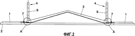
На фиг.2 показан вид исходного положения перед подъемом, где опалубка и балки не представлены.Figure 2 shows a view of the initial position before lifting, where the formwork and beams are not represented.
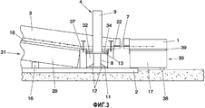
На фиг.3 показана с увеличением часть стен и кровли, где представлены балки, цилиндры, опалубка, а также клин стен.Figure 3 shows with increasing part of the walls and the roof, which presents the beams, cylinders, formwork, as well as the wedge of the walls.
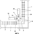
На фиг.4 показаны в плане части опоры брусков на диски после подъема.Figure 4 shows in plan a part of the support of the bars on the disks after lifting.
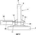
На фиг.5 показана с увеличением часть A фиг.2 подъемного средства.FIG. 5 shows, with an increase, part A of FIG. 2 of the lifting means.
На фиг.6 показан вид поднимаемой кровли во втором промежуточном положении подъема.Figure 6 shows a view of a raised roof in a second intermediate lifting position.
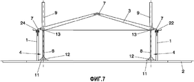
На фиг.7 показан вид со стороны фронтона кровли в полностью поднятом конечном положении со стенами, стоящими в вертикальном положении.7 shows a view from the side of the pediment of the roof in a fully raised end position with the walls standing in an upright position.
На фиг.8 показано расположение подъемного средства относительно балки и кровли во время подъема.On Fig shows the location of the lifting means relative to the beam and the roof during lifting.
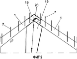
На фиг.9 показаны в изометрии части первой опалубки, скрепленные со стенами для соединения стен.FIG. 9 is an isometric view of portions of a first formwork fastened to walls to connect walls.
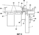
На фиг.10 показана с увеличением часть кровли, стен, частей второй опалубки соединения стен с кровлей, балки и фланцы.Figure 10 shows with increasing part of the roof, walls, parts of the second formwork connecting the walls with the roof, beams and flanges.
Изобретение представляет частично сборное здание, оборудованное стенами (1), полом (2) и кровлей (3), и способ строительства здания, обеспечивающий одновременный подъем стен (1) и кровли (3) с использованием подъемного средства (4).The invention provides a partially prefabricated building equipped with walls (1), floor (2) and roof (3), and a method of building a building that simultaneously raises walls (1) and roof (3) using lifting means (4).
На фиг.1 показан пол (2), на котором формуются стены (1) и кровля (3) с установкой опалубки (30) стен и опалубки (31) кровли, как показано на фиг.3. Опалубка (31) кровли содержит первые трубы (29), установленные продольно и параллельно на первых клиньях (16), обеспечивающих первым трубам (29) наклон, необходимый для образования кровли (3). На первых трубах (29) располагаются первые щиты (18) опалубки, образующие приемную емкость, в которую укладывается бетон. Опалубка (30) стен содержит вторые трубы (29), установленные продольно и горизонтально на полу с помощью вторых клиньев (38). На вторых трубах (17) располагаются вторые щиты (39) опалубки, которые образуют приемную емкость, в которую укладывается бетон. Стены (1) включают в себя проемы (5) для дверей и окон, где необходимо. Трубы (29, 17) и клинья (16, 38) имеют такие размеры, что их можно удалять из здания через проемы (5) дверей и/или окон.Figure 1 shows the floor (2) on which the walls (1) and the roof (3) are formed with the installation of the formwork (30) of the walls and the formwork (31) of the roof, as shown in figure 3. The roof formwork (31) contains the first pipes (29) installed longitudinally and parallel to the first wedges (16), providing the first pipes (29) with the slope necessary for the formation of the roof (3). On the first pipes (29), the first formwork panels (18) are located, forming the receiving tank into which the concrete is laid. The wall formwork (30) contains second pipes (29) mounted longitudinally and horizontally on the floor with the help of second wedges (38). On the second pipes (17) are the second formwork panels (39), which form the receiving tank into which the concrete is laid. Walls (1) include openings (5) for doors and windows where necessary. Pipes (29, 17) and wedges (16, 38) are of such dimensions that they can be removed from the building through the openings (5) of doors and / or windows.
На фиг.1 также показано, что стены (1) формуются в опалубке (30) стен, установленной вокруг опалубки (31) кровли. Во время процесса формовки стен (1) и кровли (3) вначале арматурные стержни периодического профиля (7) вводят в качестве соединительного средства (7) на смежных концах стен (1) и кровли (3) для соединения после затвердевания бетона стен (1) и кровли (3) полужестким соединением между каждой одной стеной (1) и кровлей (3).Figure 1 also shows that the walls (1) are formed in the formwork (30) of the walls mounted around the formwork (31) of the roof. During the process of forming the walls (1) and the roof (3), the reinforcing bars of the periodic profile (7) are first introduced as connecting means (7) at the adjacent ends of the walls (1) and the roof (3) to connect after the concrete walls have hardened (1) and roofs (3) with a semi-rigid connection between each one wall (1) and the roof (3).
Перед формованием стен (1) и кровли (3) гидравлические домкраты (4) устанавливаются вблизи углов кровли (см. фиг.1 и 3) в качестве подъемного средства (4), содержащего поршень (8), установленный на пол (2) в качестве фиксированной части (8), и подвижный кожух (9) в качестве перемещающейся части (9), действием гидравлического привода перемещающейся вдоль наружной поверхности поршня (8). Как показано на фиг.5, для улучшения устойчивости подъемного средства (4) первый диск (11), установленный на полу (2), прочно соединяется с поршнем (8), а также с (первыми) усиливающими кронштейнами (12) между первым диском (11) и поршнем (8) для предотвращения чрезмерной деформации или даже оседания пола (2).Before forming the walls (1) and the roof (3), hydraulic jacks (4) are installed near the corners of the roof (see Figs. 1 and 3) as lifting means (4) containing a piston (8) installed on the floor (2) in as a fixed part (8), and a movable casing (9) as a moving part (9), by the action of a hydraulic drive moving along the outer surface of the piston (8). As shown in FIG. 5, in order to improve the stability of the lifting means (4), the first disk (11) mounted on the floor (2) is firmly connected to the piston (8), as well as to the (first) reinforcing arms (12) between the first disk (11) and the piston (8) to prevent excessive deformation or even subsidence of the floor (2).
На фиг.2, 6 и 7 схематично показано расположение конструкции, соответственно, в первом исходном положении со стенами в горизонтальном положении, втором промежуточном положении и третьем конечном положении со стенами, стоящими вертикально, и полностью поднятой конструкцией.Figure 2, 6 and 7 schematically shows the location of the structure, respectively, in the first initial position with the walls in a horizontal position, the second intermediate position and the third final position with the walls standing upright, and the structure is fully raised.
Затем, как показано на фиг.3, 4, 5 и 8, выполняется соединение между кровлей и кожухами (9) с балками (32), проходящими параллельно сторонам кровли (3) и, по существу, на концах сторон, вблизи углов. Балки (32) содержат бруски (34), выступающие от концов балок (32). Аналогично, кожухи (9) фиксируются в своей нижней части к различным вторым дискам (13), которые, перед подъемом, располагаются под брусками (34) балок (32), находящихся на каждом углу кровли (3). Ширина балок (32), по существу, равна ширине опалубки (30) стен. Вторые подкрепляющие кронштейны (15) располагаются между вторым диском (13) и кожухом (9).Then, as shown in FIGS. 3, 4, 5 and 8, a connection is made between the roof and the casings (9) with beams (32) extending parallel to the sides of the roof (3) and, essentially, at the ends of the sides, near the corners. Beams (32) contain bars (34) protruding from the ends of the beams (32). Similarly, the casings (9) are fixed in their lower part to various second disks (13), which, before lifting, are located under the bars (34) of the beams (32) located at each corner of the roof (3). The width of the beams (32) is essentially equal to the width of the wall formwork (30). The second reinforcing brackets (15) are located between the second disk (13) and the casing (9).
На фиг.2, 6 и 7 показано возведение кровли (3) с помощью синхронизированного приведения в движение кожухов (9) из исходного положения, в котором стены (1) и кровля (3) опираются на пол (2) в конечное положение со стенами (1), стоящими вертикально. Полужесткие соединения, созданные между стенами (1) и кровлей (3) первыми стержнями (7), обеспечивают под действием веса стен (1), при совместном подъеме кровли и стен (1), поворот и перемещение стен (1) относительно нижней кромки, когда кровля (3) поднимается, до установки стен (1), по существу, в вертикальное положение. Затем стены (1) обвязываются и крепятся обычными средствами и затем, как показано на фиг.9, стены (1) соединяются вместе с закреплением внутри и снаружи углов стен (1) различных частей первой опалубки (19), образующих квадрат, и выполнением бетонирования внутри первой опалубки (19). Боковые кромки стен (1) включают в себя различные стержни (20), создающие более высокую прочность соединения между стенами (1).Figures 2, 6 and 7 show the erection of the roof (3) by synchronously driving the housings (9) from the starting position, in which the walls (1) and the roof (3) rest on the floor (2) in the final position with the walls (1) standing upright. Semi-rigid joints created between the walls (1) and the roof (3) by the first rods (7) provide, under the action of the weight of the walls (1), while lifting the roof and walls (1), the walls (1) rotate and move relative to the lower edge, when the roof (3) rises, before the walls (1) are installed, essentially in a vertical position. Then, the walls (1) are tied and fastened by conventional means, and then, as shown in Fig. 9, the walls (1) are connected together with fixing inside and outside the corners of the walls (1) of the various parts of the first formwork (19) forming a square and concreting inside the first formwork (19). The lateral edges of the walls (1) include various rods (20), creating a higher bond strength between the walls (1).
На фиг.10 показано, как стены (1) соединяются с кровлей (3) с укладкой бетона внутри второй опалубки из различных частей (21, 22), установленной в углах, образованных стенами (1) с кровлей (3). Части (21, 22) второй опалубки содержат металлические швеллера внутренних частей (21) второй опалубки, приваренные к балкам, и наружные части (21) второй опалубки в форме приемной емкости.Figure 10 shows how the walls (1) are connected to the roof (3) with concrete laying inside the second formwork from various parts (21, 22) installed in the corners formed by the walls (1) with the roof (3). Parts (21, 22) of the second formwork comprise metal channels of the inner parts (21) of the second formwork welded to the beams, and the outer parts (21) of the second formwork in the form of a receiving tank.
Кровля (3) снабжена по своим краям проушинами (23) с загнутыми концами для создания большей прочности соединения между стенами (1) и кровлей (3). Части (22) второй опалубки крепятся к стенам (1) и/или кровле (3) с помощью фиксирующего средства (24), содержащего третьи зажимы (24), прижимающие наружные части (22) второй опалубки к стенам (1) с помощью анкерных фланцев (25), устанавливаемых с помощью множества вторых сквозных болтов (26) и различных пар гаек (27). Вторые болты (26) размещаются в отверстиях (28), расположенных по всей верхней части стены (1), получают отверстия (28), закладывая стержни перед бетонированием стены (1) и удаляя их перед затвердеванием бетона, предпочтительно не раньше четырех или пяти часов после укладки бетона, даже лучше на следующий день.The roof (3) is provided at its edges with eyes (23) with bent ends to create greater strength of the connection between the walls (1) and the roof (3). Parts (22) of the second formwork are attached to the walls (1) and / or the roof (3) using fixing means (24) containing third clamps (24) that press the outer parts (22) of the second formwork to the walls (1) using anchor flanges (25) mounted with a plurality of second through-bolts (26) and various pairs of nuts (27). The second bolts (26) are placed in the holes (28) located along the entire upper part of the wall (1), receive holes (28), laying the rods before concreting the wall (1) and removing them before the concrete has hardened, preferably not earlier than four or five hours after laying concrete, even better the next day.
Внутренние части (22) второй опалубки также создают соединение между балками (32) и кровлей (3), работающее совместно со стержнями (35), заделанными в бетон. Стержни (35) фиксируются третьими гайками (36), опирающимися на уголки (37), приваренные к 20 балкам (32), и третьи гайки (36) можно отвинчивать после прохождения подъема для высвобождения балки (32). Использование стержней (35) и гаек (36) делает возможным увеличение подъемной силы, поскольку уже затвердевшая кровля (3) работает на сжатие, обеспечивая использование балок (32) меньшего размера.The internal parts (22) of the second formwork also create a connection between the beams (32) and the roof (3), working in conjunction with the rods (35) embedded in concrete. The rods (35) are fixed with third nuts (36), supported by angles (37) welded to 20 beams (32), and the third nuts (36) can be unscrewed after passing the lift to release the beam (32). The use of rods (35) and nuts (36) makes it possible to increase the lifting force, since the already hardened roof (3) works in compression, providing the use of beams (32) of a smaller size.
Наконец домкраты (4) складывают и убирают, и если они еще не убраны, убирают первую опалубку (19) и части (21, 22) второй опалубки (21).Finally, the jacks (4) are folded and removed, and if they are not yet removed, the first formwork (19) and parts (21, 22) of the second formwork (21) are removed.
Claims (5)
боковые стены (1), соединенные с кровлей (3), с поддержанием разделения между стенами (1) и кровлей (3) с помощью соединительного средства (7), установленного между стенами (1) и кровлей (3), образующего полужесткие соединения, создающие поворотные шарниры для подъема стен (1) и кровли (3), из исходного положения, в котором стены (1) и кровля (3) опираются на пол (2), в конечное поднятое положение, в котором стены (1) установлены в вертикальном положении, где подъем выполняется с помощью подъемного средства (4), установленного в углах кровли (3), содержащего неподвижно закрепленную часть (8), установленную на полу (2), и подвижную часть (9), перемещающуюся относительно неподвижно закрепленной части (8) и соединенную с кровлей (3),
отличающийся тем, что содержит следующие этапы, на которых осуществляют:
- бетонирование пола (3) на грунте (2);
- установку на полу (2), в углах кровли (3), подъемного средства (4);
- формование стен (1) и кровли (3) на полу (2) с установкой на полу (2) опалубки (30) стен и опалубки (31) кровли и после сборки опалубки (30, 31) заполнение опалубки (30, 31) бетоном и затвердевание бетона, при этом стены (1) и кровлю (3) соединяют соединительным средством (7), создающим полужесткие соединения между стенами (1) и кровлей (3);
- совместный подъем кровли (3) и стен (1) с помощью синхронизированного приведения в движение подъемного средства (4), при этом стены (1) поднимают совместно с кровлей с поворотом и перемещением относительно нижней кромки из исходного положения, в котором стены (1) и кровля (3) опираются на пол (2), в конечное положение благодаря весу стен и полужестким соединениям, созданным с помощью соединительного средства (7); при этом подъем кровли (3) и стен (1) содержит обеспечение балок (32), параллельных сторонам кровли (3) и расположенных вблизи концов кровли (3), причем балки (32) оборудуют в своей верхней части выступающими брусками (34) на концах балок (32) для выталкивания вторыми дисками (13), прикрепленными к подвижным частям (9) подъемного средства;
- обвязку и закрепление стен (1);
- соединение стен (1) вместе;
- соединение стен (1) с кровлей (3);
- удаление подъемного средства (4).1. A method of constructing a partially prefabricated building comprising:
side walls (1) connected to the roof (3), maintaining separation between the walls (1) and the roof (3) using connecting means (7) installed between the walls (1) and the roof (3), forming semi-rigid joints, creating swivel joints for lifting the walls (1) and the roof (3), from the initial position in which the walls (1) and the roof (3) rest on the floor (2), in the final raised position, in which the walls (1) are installed in upright position, where the lift is carried out by means of lifting means (4) installed in the corners of the roof (3), containing a movably fixed part (8) mounted on the floor (2) and a movable part (9) moving relative to the fixed part (8) and connected to the roof (3),
characterized in that it contains the following stages, which carry out:
- concreting of the floor (3) on the ground (2);
- installation on the floor (2), in the corners of the roof (3), lifting equipment (4);
- molding walls (1) and roof (3) on the floor (2) with installation on the floor (2) of the formwork (30) of the walls and formwork (31) of the roof and after assembling the formwork (30, 31) filling the formwork (30, 31) concrete and hardening of concrete, while the walls (1) and the roof (3) are connected by connecting means (7), creating semi-rigid joints between the walls (1) and the roof (3);
- joint lifting of the roof (3) and walls (1) by synchronized driving of the lifting means (4), while the walls (1) are raised together with the roof with rotation and movement relative to the lower edge from the initial position in which the walls (1 ) and the roof (3) rest on the floor (2), in the final position due to the weight of the walls and semi-rigid joints created using the connecting means (7); the rise of the roof (3) and walls (1) comprises providing beams (32) parallel to the sides of the roof (3) and located near the ends of the roof (3), and the beams (32) are equipped in their upper part with protruding bars (34) on the ends of the beams (32) for pushing the second disks (13) attached to the movable parts (9) of the lifting means;
- tying and fixing walls (1);
- connecting the walls (1) together;
- the connection of the walls (1) with the roof (3);
- removal of lifting means (4).
Applications Claiming Priority (3)
| Application Number | Priority Date | Filing Date | Title |
|---|---|---|---|
| ESP201031282 | 2010-08-25 | ||
| ES201031282A ES2395104B1 (en) | 2010-08-25 | 2010-08-25 | SEMIPREFABRICATED BUILDING AND CONSTRUCTION PROCEDURE OF SUCH BUILDING |
| PCT/ES2011/070246 WO2012025645A2 (en) | 2010-08-25 | 2011-04-12 | Semi-prefabricated building and associated construction method |
Publications (2)
| Publication Number | Publication Date |
|---|---|
| RU2013112930A RU2013112930A (en) | 2014-09-27 |
| RU2558065C2 true RU2558065C2 (en) | 2015-07-27 |
Family
ID=44626922
Family Applications (1)
| Application Number | Title | Priority Date | Filing Date |
|---|---|---|---|
| RU2013112930/03A RU2558065C2 (en) | 2010-08-25 | 2011-04-12 | Partially prefabricated building and method of its erection |
Country Status (4)
| Country | Link |
|---|---|
| EP (1) | EP2610411A2 (en) |
| ES (1) | ES2395104B1 (en) |
| RU (1) | RU2558065C2 (en) |
| WO (1) | WO2012025645A2 (en) |
Families Citing this family (4)
| Publication number | Priority date | Publication date | Assignee | Title |
|---|---|---|---|---|
| CN105735654B (en) * | 2016-03-01 | 2018-02-27 | 广州建筑股份有限公司 | It is a kind of to rotate and upgrade construction method of installation and device across lifting member greatly |
| US10077572B1 (en) * | 2017-04-19 | 2018-09-18 | Hmt, Llc | Systems and methods for lifting and positioning a roof for installation on a storage tank |
| CN108374526A (en) * | 2018-02-24 | 2018-08-07 | 佛山市知而行信息科技有限公司 | The prefabricated and hanging method of long-span roofing plate |
| CN110093985B (en) * | 2019-05-20 | 2021-04-23 | 中国二十冶集团有限公司 | Single-side jacking and outward expanding method for net rack |
Citations (5)
| Publication number | Priority date | Publication date | Assignee | Title |
|---|---|---|---|---|
| US3494092A (en) * | 1967-07-05 | 1970-02-10 | Delp W Johnson | Integrated folding slab construction |
| SU672303A1 (en) * | 1977-11-30 | 1979-07-05 | Московский научно-исследовательский и проектный институт типового и экспериментального проектирования | Method of erecting building and structures |
| FR2450326A1 (en) * | 1979-03-01 | 1980-09-26 | Services Construction Sarl | Building technique for casting vertical concrete walls - uses building floor as bottom shutter for wall which is cast horizontally then raised to vertical position |
| SU1557295A1 (en) * | 1987-06-01 | 1990-04-15 | Харьковский инженерно-строительный институт | Method of erecting multistorey building by method of storey lifting |
| EP1978170A1 (en) * | 2006-01-25 | 2008-10-08 | Domingo Bengoa Saez De Cortazar | System for the construction of a semi-prefabricated building |
Family Cites Families (2)
| Publication number | Priority date | Publication date | Assignee | Title |
|---|---|---|---|---|
| US3831337A (en) * | 1972-08-02 | 1974-08-27 | D Johnson | Method of erecting foldable building structures |
| EP1775396A1 (en) * | 2005-10-12 | 2007-04-18 | Dante N. Bini | Pneumatic method and system for rapid erection of constructible structures |
-
2010
- 2010-08-25 ES ES201031282A patent/ES2395104B1/en not_active Expired - Fee Related
-
2011
- 2011-04-12 EP EP11724684.3A patent/EP2610411A2/en not_active Withdrawn
- 2011-04-12 WO PCT/ES2011/070246 patent/WO2012025645A2/en active Application Filing
- 2011-04-12 RU RU2013112930/03A patent/RU2558065C2/en not_active IP Right Cessation
Patent Citations (5)
| Publication number | Priority date | Publication date | Assignee | Title |
|---|---|---|---|---|
| US3494092A (en) * | 1967-07-05 | 1970-02-10 | Delp W Johnson | Integrated folding slab construction |
| SU672303A1 (en) * | 1977-11-30 | 1979-07-05 | Московский научно-исследовательский и проектный институт типового и экспериментального проектирования | Method of erecting building and structures |
| FR2450326A1 (en) * | 1979-03-01 | 1980-09-26 | Services Construction Sarl | Building technique for casting vertical concrete walls - uses building floor as bottom shutter for wall which is cast horizontally then raised to vertical position |
| SU1557295A1 (en) * | 1987-06-01 | 1990-04-15 | Харьковский инженерно-строительный институт | Method of erecting multistorey building by method of storey lifting |
| EP1978170A1 (en) * | 2006-01-25 | 2008-10-08 | Domingo Bengoa Saez De Cortazar | System for the construction of a semi-prefabricated building |
Also Published As
| Publication number | Publication date |
|---|---|
| WO2012025645A2 (en) | 2012-03-01 |
| WO2012025645A4 (en) | 2012-12-27 |
| ES2395104B1 (en) | 2013-12-11 |
| EP2610411A2 (en) | 2013-07-03 |
| WO2012025645A3 (en) | 2012-11-08 |
| ES2395104A1 (en) | 2013-02-08 |
| RU2013112930A (en) | 2014-09-27 |
Similar Documents
| Publication | Publication Date | Title |
|---|---|---|
| KR101630235B1 (en) | Precast truss wall structure and construction method of underground structure using thereof | |
| CN104520521B (en) | High-rise raises concept | |
| KR101574253B1 (en) | A method for construction using a twin wall structure using a PC panel | |
| KR20120096605A (en) | Bracket support type downward construction system and method | |
| JP6855296B2 (en) | Building foundation structure and its construction method | |
| RU2558065C2 (en) | Partially prefabricated building and method of its erection | |
| KR100694493B1 (en) | Downward construction method capable of using bracket support type temporary structure as working table | |
| KR101617221B1 (en) | Joint structure of remodeling modular unit for seismic retrofitting and joint method of using it | |
| US10829927B2 (en) | Vertical slip form construction system with multi-function platform, and method of constructing a building therewith | |
| KR100605514B1 (en) | Bracket support type downward construction system and construction method using the same | |
| KR200372315Y1 (en) | Moving-fabricated supporting bracket structure of downward construction system | |
| JP3999931B2 (en) | Construction method of tower structure | |
| KR101518586B1 (en) | Method for constructing precast concrete structural frame building using the precast concrete tilt-up frame | |
| KR101324884B1 (en) | Hybrid building construction method combining dry type and wet type | |
| KR101880813B1 (en) | A sandwitch pc pannel structure and construction method of structure using thereof | |
| KR102211218B1 (en) | A Construction Method for Pre-Constructing Staircase and Constructing Materials Used therein | |
| JP3137448B2 (en) | Construction method of concrete main tower | |
| JP5003253B2 (en) | RC beam construction method | |
| JPH07300817A (en) | Concrete-filled steel pipe truss pier and construction method | |
| KR102679042B1 (en) | PC half-slab construction method for quick construction of precast concrete apartment house | |
| RU2716319C1 (en) | Method of erection of buildings and structures | |
| KR101409249B1 (en) | Top Down Construction method Using Method Of Steel Hybrid Girder Construction | |
| EP1978170A1 (en) | System for the construction of a semi-prefabricated building | |
| JP2761526B2 (en) | How to build structures | |
| EP3495578B1 (en) | A method for realising a prefabricated wall for a colum and beam construction made of reinforced concrete, and a method for realising the construction |
Legal Events
| Date | Code | Title | Description |
|---|---|---|---|
| MM4A | The patent is invalid due to non-payment of fees |
Effective date: 20160413 |