RU2553160C2 - Energy extraction from gases in blast-furnace unit - Google Patents
Energy extraction from gases in blast-furnace unit Download PDFInfo
- Publication number
- RU2553160C2 RU2553160C2 RU2012120577/02A RU2012120577A RU2553160C2 RU 2553160 C2 RU2553160 C2 RU 2553160C2 RU 2012120577/02 A RU2012120577/02 A RU 2012120577/02A RU 2012120577 A RU2012120577 A RU 2012120577A RU 2553160 C2 RU2553160 C2 RU 2553160C2
- Authority
- RU
- Russia
- Prior art keywords
- blast
- heat
- blast furnace
- gas
- heating device
- Prior art date
Links
Images
Classifications
-
- F—MECHANICAL ENGINEERING; LIGHTING; HEATING; WEAPONS; BLASTING
- F27—FURNACES; KILNS; OVENS; RETORTS
- F27B—FURNACES, KILNS, OVENS, OR RETORTS IN GENERAL; OPEN SINTERING OR LIKE APPARATUS
- F27B1/00—Shaft or like vertical or substantially vertical furnaces
- F27B1/10—Details, accessories, or equipment peculiar to furnaces of these types
- F27B1/22—Arrangements of heat-exchange apparatus
-
- C—CHEMISTRY; METALLURGY
- C21—METALLURGY OF IRON
- C21B—MANUFACTURE OF IRON OR STEEL
- C21B7/00—Blast furnaces
- C21B7/002—Evacuating and treating of exhaust gases
-
- F—MECHANICAL ENGINEERING; LIGHTING; HEATING; WEAPONS; BLASTING
- F27—FURNACES; KILNS; OVENS; RETORTS
- F27B—FURNACES, KILNS, OVENS, OR RETORTS IN GENERAL; OPEN SINTERING OR LIKE APPARATUS
- F27B1/00—Shaft or like vertical or substantially vertical furnaces
- F27B1/10—Details, accessories, or equipment peculiar to furnaces of these types
-
- C—CHEMISTRY; METALLURGY
- C21—METALLURGY OF IRON
- C21B—MANUFACTURE OF IRON OR STEEL
- C21B2100/00—Handling of exhaust gases produced during the manufacture of iron or steel
- C21B2100/40—Gas purification of exhaust gases to be recirculated or used in other metallurgical processes
- C21B2100/44—Removing particles, e.g. by scrubbing, dedusting
-
- C—CHEMISTRY; METALLURGY
- C21—METALLURGY OF IRON
- C21B—MANUFACTURE OF IRON OR STEEL
- C21B2100/00—Handling of exhaust gases produced during the manufacture of iron or steel
- C21B2100/60—Process control or energy utilisation in the manufacture of iron or steel
- C21B2100/62—Energy conversion other than by heat exchange, e.g. by use of exhaust gas in energy production
Abstract
Description
Данное изобретение относится к очистке газов в установке доменной печи и, более конкретно, к извлечению энергии из колошникового газа доменной печи в турбодетандере.This invention relates to the purification of gases in the installation of a blast furnace and, more specifically, to the extraction of energy from the blast furnace gas of the blast furnace in a turboexpander.
Как хорошо известно, газы играют фундаментальную роль в работе доменной печи. Первым существенным потоком газа является воздушный поток (или «вдуваемый воздух»), который вдувается на переходе между областями заплечиков и пода доменной печи и который вступает в реакцию с шихтовым материалом (железная руда, кокс, флюс и т.д.). Перед подачей вдуваемого воздуха в фурмы доменной печи он подогревается за счет прохождения через регенеративные воздухонагреватели (также известные как кауперы), которые обычно подогреваются посредством сжигания отходящего газа доменной печи. Атмосферный воздух, впущенный выше по потоку от каупера, образует «холодное дутье», тогда как предварительно нагретый вдуваемый воздух ниже по потоку от каупера называется «горячее дутье».As is well known, gases play a fundamental role in the operation of a blast furnace. The first significant gas stream is the air stream (or “blown air”), which is blown in at the transition between the regions of the shoulders and the blast furnace and which reacts with the charge material (iron ore, coke, flux, etc.). Before blowing air is supplied to the tuyeres of the blast furnace, it is heated by passing through regenerative air heaters (also known as coolers), which are usually heated by burning the blast furnace off-gas. Atmospheric air admitted upstream of the Cowper forms a “cold blast”, while preheated blowing air downstream of the Cowper is called “hot blast”.
Другим основным газовым потоком в доменной печи является газ, выходящий из доменной печи у колошника, известный как «колошниковый газ» или «доменный газ», который является побочным продуктом доменной печи и вырабатывается, когда железная руда восстанавливается коксом и/или другими видами топлива в рафинированное от примесей железо. Обычно колошниковый газ доменной печи используется в качестве топлива на сталелитейных заводах или в каупере, но его также можно сжигать в бойлерах и электростанциях. Он также может быть соединен с природным газом или коксовым газом до его сгорания или с вспомогательной горелкой с газом с более высокой теплотворной способностью или для поддержания горения предусмотрена нефть.The other main gas stream in the blast furnace is the gas leaving the blast furnace at the top, known as “blast furnace gas” or “blast furnace gas”, which is a by-product of the blast furnace and is produced when iron ore is reduced by coke and / or other fuels in refined iron. Typically, blast furnace top gas is used as fuel in steel mills or in a cooler, but it can also be burned in boilers and power plants. It can also be combined with natural gas or coke oven gas before it is burned, or with an auxiliary gas burner with a higher calorific value, or oil is provided to maintain combustion.
Также хорошо известно, что доменные печи на протяжении десятилетий работают с внутренним избыточным давлением, которое вместе с надлежащими размерами печи позволяет осуществить значительное увеличение конверсии материалов и энергии и, таким образом, объем выпуска передельного чугуна.It is also well known that blast furnaces have been operating for decades with internal overpressure, which, together with the proper dimensions of the furnace, allows a significant increase in the conversion of materials and energy and, thus, the output of pig iron.
Разумеется, работа при внутреннем избыточном давлении также подразумевает значительные дополнительные расходы, связанные с оборудованием и функционированием. Более конкретно, требуется выработка сжатого воздуха с подходящим уровнем давления подачи в компрессоре холодного дутья (или воздуходувке) для образования холодного дутья. Также типичным для работы при избыточном давлении является то, что газ, выходящий из колошникового газа, находится под давлением, значительно выше атмосферного давления. Однако колошниковый газ все еще содержит горючие компоненты, главным образом оксид углерода и, в меньшей степени, водород, и может использоваться в качестве дымового газа с низкой теплотворной способностью для производства тепловой или механической и электрической энергии.Of course, working with internal overpressure also entails significant additional costs associated with equipment and operation. More specifically, it requires the generation of compressed air with a suitable supply pressure level in a cold blast compressor (or blower) to form a cold blast. It is also typical for operation at overpressure that the gas leaving the top gas is at a pressure well above atmospheric pressure. However, blast furnace gas still contains combustible components, mainly carbon monoxide and, to a lesser extent, hydrogen, and can be used as flue gas with low calorific value for the production of thermal or mechanical and electrical energy.
Выходящий из доменной печи колошниковый газ также несет значительное количество твердого вещества, главным образом в пылеобразной форме. Перед последующим использованием колошникового газа необходимо удалить этот твердый материал. Это обычно достигают в газоочистительной вспомогательной установке доменной печи, которая обычно содержит оборудование для первого сухого разделения с гравитационным сепаратором (пылеуловитель) и/или с осевым циклоном и устройство для последующей глубокой очистки (сепаратор мокрого разделения). За счет мокрой очистки температура колошникового газа падает примерно на 100°C, насыщена водяным паром и включает в себя дополнительно текучие водяные капли.The blast furnace gas leaving the blast furnace also carries a significant amount of solid, mainly in dust form. Prior to the subsequent use of blast furnace gas, this solid material must be removed. This is usually achieved in a gas cleaning auxiliary installation of a blast furnace, which usually contains equipment for the first dry separation with a gravity separator (dust collector) and / or with an axial cyclone and a device for subsequent deep cleaning (wet separation separator). Due to wet cleaning, the temperature of the top gas drops by about 100 ° C, is saturated with water vapor and includes additionally flowing water droplets.
После очистки, в дополнение к использованию тепловой энергии колошникового газа, давно известным является извлечение пневматической энергии сжатого колошникового газа доменной печи в турбодетандере. В турбине колошниковый газ расширяется, приближаясь к атмосферному давлению, одновременно совершая механическую работу. Ротор турбины может быть сочленен, например, с электрическим генератором, с компрессором холодного дутья или с любой другой нагрузкой.After purification, in addition to using the thermal energy of the top gas, it has long been known to extract the pneumatic energy of the compressed top gas of a blast furnace in a turboexpander. In the turbine, the top gas expands, approaching atmospheric pressure, while simultaneously performing mechanical work. The turbine rotor can be coupled, for example, with an electric generator, with a cold blast compressor, or with any other load.
Сейчас также известно, что производительность такого турбодетандера (также называемого Top pressure recovery turbine - TRT (газовой утилизационной бескомпрессорной турбиной - ГУБТ)) может быть увеличена посредством нагрева очищенного и, таким образом, охлажденного колошникового газа непосредственно перед его входом в турбину. С этой целью предлагается осуществлять предварительный нагрев очищенного колошникового газа выше по потоку от турбины за счет сжигания расширенного колошникового газа. Альтернативно, JP 62074009 предлагает отвод теплоты из грануляции шлака и передачу этого тепла холодному очищенному газу выше по потоку от ГУБТ с помощью теплообменника.Now it is also known that the performance of such a turboexpander (also called Top pressure recovery turbine - TRT (gas recovery non-compressor turbine - GUBT)) can be increased by heating the purified and, thus, cooled top gas directly before it enters the turbine. To this end, it is proposed to pre-heat the purified blast furnace gas upstream of the turbine by burning the expanded blast furnace gas. Alternatively, JP 62074009 proposes the removal of heat from slag granulation and the transfer of this heat to the cold purified gas upstream of the HUBT using a heat exchanger.
FR 2663685 описывает способ извлечения энергии из доменного газа. Доменный газ проходит через фильтрацию пыли тонкой и/или грубой очистки, затем через турбину (восстановления давления), сочлененную с силовым генератором, и далее к газопроводу для последующего использования. Пропорция газа (3-15%, предпочтительно примерно 5%) перепускается перед турбодетандером (12), если необходимо, через компрессор, и сжигается в камере сгорания, возможно с обогащением посредством топлива высокой калорийности, например природного газа или коксового газа. Затем газообразные продукты сгорания расширяются в газовой турбине. Газовая турбина может быть сопряжена со своим собственным генератором или с генератором турбодетандера посредством муфты. Предпочтительно, температура не пропущенной через перепуск части очищенного доменного газа поднимается вверх перед впуском в утилизационную турбину за счет теплового обмена с газообразными продуктами сгорания в газовой турбине. Часть потока холодного дутья может сжигаться в газовой турбине.FR 2663685 describes a method for extracting energy from a blast furnace gas. Blast furnace gas passes through fine and / or coarse dust filtration, then through a turbine (pressure recovery) connected to a power generator, and then to the gas pipeline for subsequent use. The proportion of gas (3-15%, preferably about 5%) is bypassed before the turboexpander (12), if necessary, through a compressor, and burned in the combustion chamber, possibly enriched with high-calorific fuel, for example natural gas or coke oven gas. Then the gaseous products of combustion expand in the gas turbine. A gas turbine can be coupled to its own generator or to a turboexpander generator via a coupling. Preferably, the temperature of the portion of the cleaned blast furnace gas that is not passed through the bypass rises before it enters the recovery turbine due to heat exchange with the gaseous products of combustion in the gas turbine. Part of the cold blast stream may be burned in a gas turbine.
Целью данного изобретения является создание другого, улучшенного способа извлечения энергии из колошникового газа в установке доменной печи с помощью ГУБТ.The aim of this invention is the creation of another, improved method of extracting energy from blast furnace gas in the installation of a blast furnace using HUBT.
Эта цель достигнута посредством способа и установки, заявленных в независимых пунктах формулы изобретения.This goal is achieved through the method and installation, as claimed in the independent claims.
Данное изобретение предлагает оптимизированный способ управления потоками газа в установке доменной печи, который позволяет эксплуатировать ГУБТ с повышенной производительностью, а именно предлагается способ извлечения энергии из колошникового газа доменной печи в установке доменной печи с системой утилизационной турбины колошникового газа (турбодетандер), содержащей по меньшей мере один компрессор сжатого холодного воздушного дутья (холодного/воздушного дутья), соединенный по меньшей мере с одним подогревателем воздушного дутья, включающий направление потока сжатого колошникового газа, выделенного доменной печью, в устройство очистки колошникового газа и подачу в турбодетандер, сочлененный с устройством потребления энергии (нагрузкой). Согласно предлагаемому способу из потока сжатого холодного дутья выше по потоку от подогревателей холодного дутья (т.е. каупер или подобное) извлекают тепло, и затем это тепло передают (по меньшей мере, частично) в холодный поток очищенного колошникового газа выше по потоку от турбодетандера. Извлечение тепла из холодного дутья предпочтительно, так как оно циркулирует в трубопроводе холодного дутья по направлению к подогревателям, не потребляя такого холодного дутья для нагрева очищенного колошникового газа.The present invention provides an optimized method for controlling gas flows in a blast furnace installation, which allows the operation of high-pressure gas turbine with increased productivity, namely, a method for extracting energy from blast furnace gas in a blast furnace installation with a top gas utilization turbine system (turboexpander) containing at least one compressed cold air blast compressor (cold / air blast) connected to at least one air blast heater, including the direction of flow of compressed blast furnace gas emitted by the blast furnace into the blast furnace gas purification device and supply to a turboexpander coupled to an energy consumption device (load). According to the proposed method, heat is extracted from the compressed cold blast stream upstream from the cold blast heaters (i.e., cooler or the like), and then this heat is transferred (at least partially) to the cold stream of purified blast furnace gas upstream of the turbine expander . Extraction of heat from a cold blast is preferable since it circulates in the cold blast pipeline towards the heaters without consuming such cold blast to heat the cleaned top gas.
Таким образом, температура холодного дутья может быть снижена перед регенеративными воздухонагревателями и, одновременно, может быть увеличена температура холодного очищенного колошникового газа, что улучшает производительность как каупера, так и ГУБТ. Действительно, известно, что повышение температуры колошникового газа до ГУБТ улучшает ее производительность и помогает избежать рисков обледенения, в то время как уменьшение температуры холодного дутья до каупера улучшает производительность этого этапа предварительного нагрева. Более конкретно, более низкая температура холодного дутья увеличивает нагревательную способность каупера.Thus, the temperature of the cold blast can be lowered in front of the regenerative air heaters and, at the same time, the temperature of the cold cleaned top gas can be increased, which improves the performance of both the cooler and the HUBT. Indeed, it is known that increasing the temperature of blast furnace gas to HLBT improves its productivity and helps to avoid icing risks, while lowering the temperature of the cold blast to the cooler improves the productivity of this preheating stage. More specifically, a lower cold blast temperature increases the heating capacity of the cooler.
Необходимо понять, что, в то время как в установках доменных печей согласно уровню техники необходимую для предварительного нагрева очищенного колошникового газа энергию получали посредством сжигания или извлечения из внешней среды, например грануляции шлака, и извлеченное тепло из холодного дутья растрачивалось попусту, преимущество данного изобретения состоит в том, что ввод холодного дутья и очищенного колошникового газа в отношения теплообмена будет применимо для улучшенной производительности как каупера, так и турбины.It should be understood that while in blast furnace installations according to the prior art, the energy necessary for preheating the cleaned top gas was obtained by burning or extracting from the external environment, for example, slag granulation, and the extracted heat from cold blast wasted, the advantage of this invention is in that the introduction of cold blast and purified blast furnace gas into the heat exchange relationship will be applicable for improved performance of both the cooler and the turbine.
Особо существенным аспектом данного изобретения является то, что получают своего рода «саморегулирующийся» теплообмен между холодным дутьем и охлажденным, очищенным колошниковым газом. Действительно, условия потока холодного дутья выше по потоку от доменной печи оказывают воздействие на условия потока колошникового газа ниже по потоку от доменной печи (и наоборот), и из этого следует, что ввод этих двух потоков в отношения теплообмена автоматически компенсирует изменения на одной стороне или на другой.A particularly significant aspect of the present invention is that a kind of “self-regulating” heat exchange is obtained between cold blast and a cooled, purified blast furnace gas. Indeed, the conditions of the flow of cold blast upstream from the blast furnace affect the conditions of the flow of blast furnace gas downstream of the blast furnace (and vice versa), and it follows that the introduction of these two flows into the heat exchange relations automatically compensates for changes on one side or another.
Следует отметить, что данный процесс является более простым, чем описанный в FR 2663685 процесс, так как в настоящем процессе не затрагивается газовый поток холодного дутья, за исключением уменьшения нагрева и, прежде всего, не отбирается частично для сжигания с колошниковым газом в газовой турбине.It should be noted that this process is simpler than the process described in FR 2663685, since the gas flow of cold blast is not affected in this process, with the exception of a decrease in heating and, first of all, is not partially selected for burning with top gas in a gas turbine.
По существу, данный способ предлагает более простой и эффективный путь предварительного нагрева очищенного колошникового газа до ГУБТ, что приносит пользу в экономическом плане для всей установки.Essentially, this method offers a simpler and more efficient way of preheating the purified blast furnace gas to HUBT, which is economically beneficial for the entire installation.
Данное изобретение также относится к установке для извлечения энергии из колошникового газа доменной печи, содержащей:This invention also relates to a plant for extracting energy from blast furnace top gas, comprising:
- по меньшей мере один компрессор холодного дутья,at least one cold blast compressor,
- по меньшей мере один подогреватель воздушного дутья для нагрева сжатого холодного дутья, полученного по меньшей мере в одном компрессоре холодного дутья, и подачи его после нагрева в доменную печь,- at least one air blast heater for heating the compressed cold blast obtained in at least one cold blast compressor and supplying it after heating to a blast furnace,
- устройство очистки колошникового газа, выпущенного из доменной печи,- a device for cleaning blast furnace gas discharged from a blast furnace,
- турбодетандер, имеющий выходной вал, сочлененный с устройством потребления энергии и расположенный ниже по потоку от устройства очистки колошникового газа,- a turboexpander having an output shaft coupled to the energy consumption device and located downstream of the top gas purification device,
- подогревающее устройство очищенного колошникового газа, расположенное между устройством очистки колошникового газа и турбодетандером,- a heating device for cleaned top gas located between the device for cleaning up top gas and a turboexpander,
отличающейся тем, что она содержит средство для извлечения тепла из сжатого холодного воздушного дутья и его, по меньшей мере частичной, передачи очищенному колошниковому газу в подогревающем устройстве.characterized in that it comprises means for extracting heat from the compressed cold air blast and at least partially transferring it to the cleaned top gas in a heating device.
Предпочтительные варианты осуществления данного способа и установки доменной печи изложены в соответствующих зависимых пунктах формулы изобретения.Preferred embodiments of this method and installation of a blast furnace are set forth in the respective dependent claims.
Следует отметить, что для извлечения тепла из сжатого холодного дутья и его, по меньшей мере частичной, передачи в очищенный колошниковый газ может быть использована любая подходящая технология. В этой связи можно использовать любой подходящий тип теплообменника в сочетании с контуром теплоносителя. Возможным типом системы теплообмена является так называемая «тепловая трубка» (прямого или кольцевого типа), где участок испарения расположен на стороне холодного дутья, а участок конденсации - на стороне очищенного колошникового газа.It should be noted that any suitable technology can be used to extract heat from the compressed cold blast and at least partially transfer it to the purified blast furnace gas. In this regard, any suitable type of heat exchanger can be used in conjunction with the heat transfer circuit. A possible type of heat transfer system is the so-called “heat pipe” (direct or ring type), where the evaporation section is located on the cold blast side and the condensation section is on the side of the cleaned blast furnace gas.
Данное изобретение будет описано с помощью примера со ссылкой на прилагаемые чертежи, на которых показано:The invention will be described by way of example with reference to the accompanying drawings, in which:
Фиг. 1 - принципиальная схема первого варианта осуществления установки доменной печи с системой извлечения энергии газа,FIG. 1 is a schematic diagram of a first embodiment of a blast furnace installation with a gas energy extraction system,
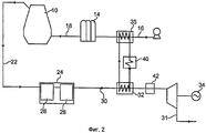
Фиг. 2 - принципиальная схема альтернативного варианта осуществления установки доменной печи с системой извлечения энергии газа.FIG. 2 is a schematic diagram of an alternative embodiment of a blast furnace installation with a gas energy extraction system.
Первый вариант осуществления представляемой установки доменной печи схематично изображен на фиг. 1 (представлено только оборудование для очистки/кондиционирования воздуха). Ссылочная позиция 10 обозначает доменную печь, к которой подается поток горячего дутья из системы воздушного дутья, содержащей воздуходувку 12 (или компрессор) и устройство предварительного нагрева, содержащее комплект из трех регенеративных воздухонагревателей 14, как является обычным в уровне техники. Воздуходувка 12 сжимает воздух и образует поток холодного дутья, который течет через трубопровод 16 холодного дутья к регенеративным воздухонагревателям 14. Поток холодного дутья нагревается в регенеративных воздухонагревателях до температур в порядке от 900°C до 1300°C и через трубопровод 18 горячего дутья течет к фурмам (не показаны), где поток горячего дутья впрыскивается в доменную печь 10.A first embodiment of the inventive blast furnace installation is shown schematically in FIG. 1 (only equipment for cleaning / air conditioning is provided).
Вышедший из доменной печи 10 колошниковый газ, по меньшей мере частично, направляется в турбодетандер (утилизационную турбину) 20 колошникового газа для извлечения из него пневматической энергии. Ссылочная позиция 22 обозначает трубопровод отходящего газа, который отводит колошниковый газ к устройству (вспомогательной установке) 24 очистки колошникового газа. Устройство 24 очистки колошникового газа может содержать пневматический сепаратор 26, последовательно соединенный с сепаратором 28 мокрого разделения. В устройстве 24 может быть реализован любой тип технологии очистки.The blast furnace gas exiting the
Очищенный поток колошникового газа подается через трубопровод 30 на турбодетандер 20 посредством подогревающего устройства 32 с целью подогрева потока колошникового газа, который охлажден вследствие процесса очистки в устройстве 24. В турбодетандере 20 очищенный колошниковый газ расширяется со снижением давления и температуры и передает механическую работу на нагрузку 34 (здесь изображена в виде генератора), соединенную с выходным валом турбодетандера. Расширенный колошниковый газ ниже по потоку от турбодетандера 20 через выпускной трубопровод 31 может быть возвращен в сеть очищенного газа или транспортироваться на предприятия пользователя/потребителя, такие как, например, электростанция.The cleaned blast furnace gas stream is fed through the
Становится понятным, что данная установка доменной печи содержит средства для извлечения тепла из сжатого холодного дутья и его передачи, по меньшей мере частично, в очищенный колошниковый газ в подогревающем устройстве 32. Предпочтительно, это достигается посредством установленного на трубопроводе 16 холодного дутья теплообменника 35 (теплообменник холодного дутья), транспортирующего сжатый холодный воздух к регенеративным воздухонагревателям 14. В теплообменнике 35 холодное дутье водят в теплообмен (но без смешивания) с теплоносителем из контура теплообмена, обозначенным ссылочной позицией 36. Предпочтительно, контур теплообмена содержит насосную систему (не показана), которая направляет теплоноситель из теплообменника 35 к подогревающему устройству 32, где извлеченное тепло, по меньшей мере частично, передается очищенному колошниковому газу.It becomes clear that this blast furnace installation comprises means for extracting heat from the compressed cold blast and transferring it, at least partially, to the cleaned top gas in the
Извлечение тепла из холодного дутья для его передачи в очищенный колошниковый газ обеспечивает очень предпочтительный способ подогрева очищенного газа перед его расширением в системе ГУБТ. Это также увеличивает производительность как регенеративных воздухонагревателей 14, так и турбодетандера 20. По сравнению с известными способами, в которых тепло холодного дутья растрачивалось и подогрев очищенного колошникового газа требовал использования горелок или подобного, получают «саморегулирующийся эффект». Действительно, режимы потока колошникового газа выше и ниже по потоку от доменной печи связаны, и следующий пример показывает сущность их работы.Extraction of heat from the cold blast for its transfer to the cleaned top gas provides a very preferred way of heating the purified gas before expanding it in the HUBT system. This also increases the performance of both the
ПримерExample
Чем выше давление колошникового газа (TGP), тем выше давление горячего дутья (HBP): HBP=TGP+dP, где dP - это потеря давления в линии дутья, доменной печи и устройстве 24 очистки колошникового газа перед турбодетандером 20 (dP является в большей или меньшей степени постоянной величиной, зависящей от специфики доменной печи, и находится в диапазоне от 1,0 до 2,5 бар). Таким образом, чем выше TGP, тем больше падение температуры колошникового газа (TGT) во время расширения в турбодетандере (ГУБТ) 20.The higher the blast furnace gas pressure (TGP), the higher the hot blast pressure (HBP): HBP = TGP + dP, where dP is the pressure loss in the blast line, blast furnace and blast furnace
Подогрев очищенного колошникового газа до турбодетандера 20 представляет интерес. Если очищенный колошниковый газ не подогрет, то температура колошникового газа после турбодетандера 20 будет ниже, что приведет к риску обледенения турбодетандера и снижению производства электрической энергии в генераторе 34. Однако если температура колошникового газа после турбодетандера 20 слишком высока, возникают такие проблемы, как перегрев турбодетандера 20 или сгорания уплотнений в сети чистого газа ниже по потоку от турбодетандера.Heated purified blast furnace gas to the turboexpander 20 is of interest. If the cleaned top gas is not heated, then the temperature of the top gas after the turbo-expander 20 will be lower, which will lead to the risk of icing of the turbo-expander and a decrease in the production of electric energy in the
Однако посредством нагрева колошникового газа до турбодетандера с помощью извлеченного из холодного дутья тепла получают предпочтительную схему подогрева, которая обеспечивает автоматический надлежащий нагрев. Если давление колошникового газа в доменной печи 10 увеличено, воздуходувка 12 вынуждена компенсировать это увеличение давления, и давление холодного дутья увеличивается с соответствующим увеличением температуры холодного дутья.However, by heating the blast furnace gas to the turboexpander using heat extracted from the cold blast, a preferred heating circuit is obtained that provides automatic proper heating. If the pressure of the top gas in the
Одновременно увеличивается перепад давления в турбодетандере 20. Но риски обледенения и подобное предотвращены, так как повышение давления ниже по потоку от доменной печи подразумевает увеличение давления и температуры холодного дутья выше по потоку от доменной печи 10 и, таким образом, большее количество тепла для передачи из холодного дутья в очищенный колошниковый газ через контур 36 теплообмена.At the same time, the pressure drop in the turboexpander 20 increases. But the risks of icing and the like are prevented, since increasing the pressure downstream of the blast furnace implies an increase in pressure and temperature of the cold blast upstream from the
Схожим образом, при уменьшении давления колошникового газа (например, для остановки доменной печи) температура колошникового газа перед турбодетандером 20 уменьшается, так как давление горячего дутья также падает вместе с температурой горячего дутья и для подогрева колошникового газа перед турбодетандером требуется меньше тепла. Это удобно, так как меньше тепла доступно из холодного дутья, давление которого также уменьшилось.Similarly, as the top gas pressure decreases (for example, to stop the blast furnace), the temperature of the top gas in front of the turboexpander 20 decreases, since the pressure of the hot blast also drops with the temperature of the hot air and less heat is required to heat the top gas in front of the expander. This is convenient because less heat is available from the cold blast, the pressure of which has also decreased.
В целях иллюстративности, на фиг. 1 были записаны значения температуры и давления в разных местах контура очистки газа доменной печи 10. Эти значения были рассчитаны. Как можно видеть, воздуходувка направляет сжатый воздух в трубопровод 16 холодного дутья при температуре 215°C и давлении 5,1 бар изб. (избыточного давления). После прохождения через теплоподводящую сторону теплообменника 35 температура холодного дутья составляет 105°C и давление 5 бар изб.For purposes of illustration, in FIG. 1, temperature and pressure values were recorded at different places in the gas purification circuit of the
После очистки температура колошникового газа падает до 45°C при значении давления 2,3 бар изб. Затем он протекает через теплоподводящий контур подогревающего устройства (подогревателя) 32, где температура повышается до 103°C при давлении 2,2 бар изб. Затем подогретый поток горячего газа поступает на турбодетандер 20 и выходит из нее при температуре 25°C и давлении сети.After cleaning, the temperature of the top gas drops to 45 ° C at a pressure of 2.3 bar. Then it flows through the heat-supply circuit of the heating device (heater) 32, where the temperature rises to 103 ° C at a pressure of 2.2 bar. Then, the heated hot gas stream enters and leaves turbo expander 20 at a temperature of 25 ° C and network pressure.
Передача тепла из холодного дутья в колошниковый газ осуществляется с помощью контура 36 теплообмена, который находится в гидравлическом соединении с теплоотводящей стороной теплообменника 35 и теплоподводящей стороной подогревающего устройства 32. Следует отметить, что в данном примере температура выходящего из теплообменника 35 теплоносителя составляет 170°C. После подогревающего устройства 32 теплоноситель отдает существенную часть тепла колошниковому газу и имеет температуру 75°C.Heat is transferred from the cold blast to the top gas by means of a heat exchange circuit 36, which is in hydraulic connection with the heat sink side of the
Как видно из данного примера, эта схема работы является достаточной для подогрева колошникового газа до ГУБТ посредством повышения его производительности и на уровне, который позволяет избежать риски обледенения и перегрева. Другими словами, саморегулирующийся эффект не только позволяет осуществить нагрев колошникового газа перед ГУБТ, но обеспечивают надежную и соответствующую работу системы ГУБТ внутри установки доменной печи, а также для пользователей ниже по потоку от ГУБТ.As can be seen from this example, this operation scheme is sufficient to heat blast furnace gas to the CBHT by increasing its productivity and at a level that avoids the risks of icing and overheating. In other words, the self-regulating effect not only allows heating of blast furnace gas in front of the HUBT, but also ensures reliable and appropriate operation of the HOBT system inside the blast furnace installation, as well as for users downstream of the HUBT.
Однако, как показано на фиг. 1, отведенное из холодного дутья тепло может быть достаточным при обычных условиях эксплуатации, но может появиться желание подать дополнительное тепло в очищенный колошниковый газ выше по потоку от турбодетандера 20. На фиг. 2 изображены два альтернативных или дополнительных способа обеспечения этого, где одни и те же ссылочные позиции обозначают одни и те же компоненты установки доменной печи.However, as shown in FIG. 1, the heat removed from the cold blast may be sufficient under normal operating conditions, but you may want to supply additional heat to the cleaned blast furnace gas upstream of the turboexpander 20. In FIG. 2 depicts two alternative or additional ways of ensuring this, where the same reference numbers indicate the same components of a blast furnace installation.
Во-первых, дополнительное тепло может обеспечиваться с помощью горелки или подобного устройства, обозначенного ссылочной позицией 40, установленного в контуре теплообмена на потоке теплоносителя от теплообменника 35 к подогревающему устройству 32. Кроме того, подогреватель 42 может быть установлен на трубопроводе 30 очищенного газа между подогревающим устройством и турбодетандером 20. Для дополнительных нагревателей 40 и 42 могут быть использованы любые типы технологий, такие как, например, соединенные с теплообменниками горелки.Firstly, additional heat can be provided using a burner or similar device, indicated by the
Следует отметить, что вышеприведенное описание сделано в показательных целях. Термин «теплообменник» здесь включает в себя любой подходящий тип устройства, в котором газ/воздух могут быть внесены в отношения теплообмена с другим газом или текучей средой, но без смешивания друг с другом. Может быть использована любая технология, совместимая с использованием доменной печи. Прежде всего, для передачи тепла из холодного дутья колошниковому газу могут быть использованы тепловые трубки, при этом участок конденсации был бы расположен в подогревающем устройстве 32, а участок испарения - на стороне холодного дутья. Также, для турбодетандера 20, дополнительного устройства 24 очистки колошникового газа, регенеративных воздухонагревателей 14 или контура 36 теплоносителя не требуется подробного описания, так как тип оборудования и его использование известны специалистам.It should be noted that the above description is made for illustrative purposes. The term "heat exchanger" here includes any suitable type of device in which gas / air can be introduced into a heat exchange relationship with another gas or fluid, but without mixing with each other. Any technology compatible with the use of a blast furnace can be used. First of all, heat pipes can be used to transfer heat from the cold blast to the top gas, and the condensation section would be located in the
Claims (13)
по меньшей мере один компрессор (12) сжатого холодного воздушного дутья (холодного дутья),
по меньшей мере один регенеративный воздухоподогреватель (14) воздушного дутья для нагрева сжатого холодного дутья, полученного по меньшей мере в одном компрессоре (12) сжатого холодного воздушного дутья, и подачи его после нагрева в доменную печь (10),
устройство (24) очистки колошникового газа доменной печи (10),
турбодетандер (20), имеющий выходной вал, сочлененный с устройством потребления тепловой энергии (34) и расположенный ниже по потоку от устройства (24) для очистки колошникового газа,
подогревающее устройство (32) очищенного колошникового газа, расположенное между устройством (24) очистки колошникового газа и турбодетандером (20),
отличающаяся тем, что она содержит средства для извлечения тепла из сжатого холодного воздушного дутья и его, по меньшей мере частичной, передачи очищенному колошниковому газу в подогревающем устройстве (32).7. Installation for extracting thermal energy from compressed cold air blast furnace, containing:
at least one compressor (12) of compressed cold air blast (cold blast),
at least one regenerative air heater (14) of air blast for heating the compressed cold blast obtained in at least one compressor (12) of compressed cold air blast and supplying it after heating to the blast furnace (10),
a blast furnace gas top purification device (24) (10),
a turboexpander (20) having an output shaft coupled to a thermal energy consumption device (34) and located downstream of the device (24) for purification of blast furnace gas,
a heated blast furnace gas preheater (32) located between the blast furnace gas treatment device (24) and a turboexpander (20),
characterized in that it contains means for extracting heat from compressed cold air blast and at least partially transferring it to the cleaned top gas in a heating device (32).
Applications Claiming Priority (3)
| Application Number | Priority Date | Filing Date | Title |
|---|---|---|---|
| LU91617A LU91617B1 (en) | 2009-10-19 | 2009-10-19 | Energy recovery from gases in a blast furnace plant |
| LU91617 | 2009-10-19 | ||
| PCT/EP2010/065621 WO2011048045A1 (en) | 2009-10-19 | 2010-10-18 | Energy recovery from gases in a blast furnace plant |
Publications (2)
| Publication Number | Publication Date |
|---|---|
| RU2012120577A RU2012120577A (en) | 2013-11-27 |
| RU2553160C2 true RU2553160C2 (en) | 2015-06-10 |
Family
ID=42236929
Family Applications (1)
| Application Number | Title | Priority Date | Filing Date |
|---|---|---|---|
| RU2012120577/02A RU2553160C2 (en) | 2009-10-19 | 2010-10-18 | Energy extraction from gases in blast-furnace unit |
Country Status (7)
| Country | Link |
|---|---|
| CN (1) | CN102575899B (en) |
| DE (1) | DE112010005234T5 (en) |
| IN (1) | IN2012DN03365A (en) |
| LU (1) | LU91617B1 (en) |
| RU (1) | RU2553160C2 (en) |
| TW (1) | TWI497017B (en) |
| WO (1) | WO2011048045A1 (en) |
Families Citing this family (2)
| Publication number | Priority date | Publication date | Assignee | Title |
|---|---|---|---|---|
| GB2509121B (en) * | 2012-12-21 | 2015-03-18 | Siemens Plc | Apparatus for supplying blast to a blast furnace |
| CN113717759A (en) * | 2021-08-13 | 2021-11-30 | 武汉钢铁有限公司 | Blast furnace gas desulfurization system and method based on wet dust removal |
Citations (2)
| Publication number | Priority date | Publication date | Assignee | Title |
|---|---|---|---|---|
| SU1177351A2 (en) * | 1982-12-24 | 1985-09-07 | Запорожский индустриальный институт | Blast furnace gas heating arrangement |
| FR2663685A1 (en) * | 1990-06-20 | 1991-12-27 | Zimmermann & Jansen Gmbh | PROCESS FOR RECOVERING THE ENERGY FROM GAS FROM A BLAST FURNACE, AND INSTALLATION OF A BLAST FURNACE FOR CARRYING OUT THIS PROCESS. |
Family Cites Families (13)
| Publication number | Priority date | Publication date | Assignee | Title |
|---|---|---|---|---|
| US2446388A (en) * | 1943-10-20 | 1948-08-03 | Brassert & Co | Preheating furnace blast |
| US3304074A (en) * | 1962-10-31 | 1967-02-14 | United Aircraft Corp | Blast furnace supply system |
| DE2044644C3 (en) * | 1970-09-30 | 1974-06-12 | Tsentralnoje Proiswodstwenno-Technitscheskoje Predpriatie Po Remontu, Naladke I Projektirowaniju Energetitscheskich Ustanowok Predpriaty Tschernoi Metallurgii, Moskau | Gas turbine system for driving a blast furnace wind compressor |
| FR2352886A1 (en) * | 1976-05-26 | 1977-12-23 | Air Ind | IMPROVEMENT OF PROCESSES AND PLANTS FOR SMELTING CAST IRON |
| JPS54115605A (en) * | 1978-02-28 | 1979-09-08 | Mitsui Eng & Shipbuild Co Ltd | Recovering method for energy of blast furnace top gas |
| JPS55134114A (en) * | 1979-04-09 | 1980-10-18 | Kawasaki Heavy Ind Ltd | Top pressure control unit in blast furnace |
| DE3435275C1 (en) * | 1984-09-26 | 1986-01-30 | Mannesmann AG, 4000 Düsseldorf | Blast furnace plant |
| JPS6274009A (en) | 1985-09-27 | 1987-04-04 | Sumitomo Metal Ind Ltd | Method for generating electric power by recovery of pressure from top of blast furnace |
| JPS62185810A (en) * | 1986-02-12 | 1987-08-14 | Sumitomo Metal Ind Ltd | Device for recovering heat energy of blast furnace gas |
| CN1014327B (en) * | 1988-11-23 | 1991-10-16 | 冶金工业部北京钢铁设计研究总院 | Control method for lowering temp. of blast-furnace gas |
| CN1055390A (en) * | 1990-05-30 | 1991-10-16 | 唐山工程技术学院 | Raw gas temperature control novel process and device before the bf bag filter |
| CN101074453A (en) * | 2006-09-13 | 2007-11-21 | 童裳慧 | Efficient economical dust collecting method and dust collector for iron-smelting blast furnace |
| AT505401B1 (en) * | 2008-02-15 | 2009-01-15 | Siemens Vai Metals Tech Gmbh | PROCESS FOR THE MELTING OF CRUDE IRON WITH THE RETURN OF GAS GAS WITH THE ADDITION OF HYDROCARBONS |
-
2009
- 2009-10-19 LU LU91617A patent/LU91617B1/en active
-
2010
- 2010-10-18 IN IN3365DEN2012 patent/IN2012DN03365A/en unknown
- 2010-10-18 RU RU2012120577/02A patent/RU2553160C2/en active
- 2010-10-18 WO PCT/EP2010/065621 patent/WO2011048045A1/en active Application Filing
- 2010-10-18 CN CN201080047332.5A patent/CN102575899B/en not_active Expired - Fee Related
- 2010-10-18 DE DE112010005234T patent/DE112010005234T5/en active Pending
- 2010-10-19 TW TW099135493A patent/TWI497017B/en not_active IP Right Cessation
Patent Citations (2)
| Publication number | Priority date | Publication date | Assignee | Title |
|---|---|---|---|---|
| SU1177351A2 (en) * | 1982-12-24 | 1985-09-07 | Запорожский индустриальный институт | Blast furnace gas heating arrangement |
| FR2663685A1 (en) * | 1990-06-20 | 1991-12-27 | Zimmermann & Jansen Gmbh | PROCESS FOR RECOVERING THE ENERGY FROM GAS FROM A BLAST FURNACE, AND INSTALLATION OF A BLAST FURNACE FOR CARRYING OUT THIS PROCESS. |
Also Published As
| Publication number | Publication date |
|---|---|
| TW201120382A (en) | 2011-06-16 |
| CN102575899B (en) | 2014-12-31 |
| TWI497017B (en) | 2015-08-21 |
| CN102575899A (en) | 2012-07-11 |
| LU91617B1 (en) | 2011-04-20 |
| IN2012DN03365A (en) | 2015-10-23 |
| DE112010005234T5 (en) | 2013-01-24 |
| WO2011048045A1 (en) | 2011-04-28 |
| RU2012120577A (en) | 2013-11-27 |
Similar Documents
| Publication | Publication Date | Title |
|---|---|---|
| RU2433339C2 (en) | Method to generate power in power plant by burning carbon-containing fuel in substantially pure oxygen, power plant to generate power by burning carbon-containing fuel in substantially pure oxygen, method to modify process of power generation by burning carbon-containing fuel from fuel burning in air to fuel burning in substantially pure oxygen | |
| TWI657195B (en) | A method for heating a recirculating gas stream,a method of generating power and a power generating system | |
| JP5568552B2 (en) | Cement clinker manufacturing method and cement clinker manufacturing facility | |
| US5327726A (en) | Staged furnaces for firing coal pyrolysis gas and char | |
| FI122189B (en) | METHOD AND ARRANGEMENT FOR RECOVERY OF HEAT FROM THE COMBUSTION ASH | |
| CN102016241A (en) | Oxyfuel combusting boiler system and a method of generating power by using the boiler system | |
| JP5101642B2 (en) | Optimization of low BTU fuel combustion combined cycle power plant by performance heating | |
| CN202595161U (en) | Blast furnace top gas recovery system | |
| GB2338991A (en) | Compound power-generating plant with superheated high pressure steam | |
| CN103814265A (en) | Method and system for milling fuel for oxy-fuel combustion burner | |
| KR20150100740A (en) | Energy recovery from fumes from a melting furnace with a gas turbine and heat exchangers | |
| RU2553160C2 (en) | Energy extraction from gases in blast-furnace unit | |
| RU2476600C2 (en) | Method for coal gasification and production of iron, and system used for that purpose | |
| US5435123A (en) | Environmentally acceptable electric energy generation process and plant | |
| KR20140099951A (en) | Cold wind generation from slag heat | |
| RU2109970C1 (en) | Method and device for operating combined-cycle plant (options) | |
| JPS6274009A (en) | Method for generating electric power by recovery of pressure from top of blast furnace | |
| CA2109963A1 (en) | Environmentally acceptable energy generation process and plant in a combined gas/steam generating power station | |
| RU25508U1 (en) | DEVICE FOR SUPPLYING DOMAIN GAS OF AN AIR BLAST OR POWER STEAM TURBINE INSTALLATION | |
| JP5790045B2 (en) | Hot air generator | |
| CN117308073A (en) | System and method for improving secondary air temperature at inlet of air preheater in starting of thermal power generating unit | |
| CN111074026A (en) | Blast furnace gas energy grading recovery process | |
| JPS60234905A (en) | Continuous hot blast supply apparatus for blast furnace | |
| JPS60204814A (en) | Apparatus for treating waste gas from blast furnace | |
| JPS61284508A (en) | Method for utilizing exhaust gas of blast furnace gas turbine |