RU2548627C2 - Steel frame structure with usage of u-shaped composite beam - Google Patents
Steel frame structure with usage of u-shaped composite beam Download PDFInfo
- Publication number
- RU2548627C2 RU2548627C2 RU2013138524/03A RU2013138524A RU2548627C2 RU 2548627 C2 RU2548627 C2 RU 2548627C2 RU 2013138524/03 A RU2013138524/03 A RU 2013138524/03A RU 2013138524 A RU2013138524 A RU 2013138524A RU 2548627 C2 RU2548627 C2 RU 2548627C2
- Authority
- RU
- Russia
- Prior art keywords
- main beam
- shelf
- frame structure
- steel frame
- auxiliary
- Prior art date
Links
- 229910000831 Steel Inorganic materials 0.000 title claims abstract description 82
- 239000010959 steel Substances 0.000 title claims abstract description 82
- 239000002131 composite material Substances 0.000 title description 9
- 239000004567 concrete Substances 0.000 claims abstract description 25
- 125000006850 spacer group Chemical group 0.000 claims abstract description 14
- 238000005520 cutting process Methods 0.000 claims description 9
- 239000003351 stiffener Substances 0.000 claims description 3
- 238000010276 construction Methods 0.000 abstract description 11
- 239000000126 substance Substances 0.000 abstract 1
- 238000004519 manufacturing process Methods 0.000 description 13
- 238000000034 method Methods 0.000 description 8
- 239000011248 coating agent Substances 0.000 description 6
- 238000000576 coating method Methods 0.000 description 6
- 238000005304 joining Methods 0.000 description 5
- 238000005452 bending Methods 0.000 description 4
- 238000005266 casting Methods 0.000 description 4
- 238000009408 flooring Methods 0.000 description 4
- 238000009434 installation Methods 0.000 description 4
- 239000000463 material Substances 0.000 description 4
- 238000003466 welding Methods 0.000 description 4
- 238000005516 engineering process Methods 0.000 description 2
- 239000011150 reinforced concrete Substances 0.000 description 2
- 229910000746 Structural steel Inorganic materials 0.000 description 1
- 230000010354 integration Effects 0.000 description 1
- 238000000465 moulding Methods 0.000 description 1
- 230000007847 structural defect Effects 0.000 description 1
Images


Classifications
-
- E—FIXED CONSTRUCTIONS
- E04—BUILDING
- E04B—GENERAL BUILDING CONSTRUCTIONS; WALLS, e.g. PARTITIONS; ROOFS; FLOORS; CEILINGS; INSULATION OR OTHER PROTECTION OF BUILDINGS
- E04B1/00—Constructions in general; Structures which are not restricted either to walls, e.g. partitions, or floors or ceilings or roofs
- E04B1/18—Structures comprising elongated load-supporting parts, e.g. columns, girders, skeletons
- E04B1/30—Structures comprising elongated load-supporting parts, e.g. columns, girders, skeletons the supporting parts being composed of two or more materials; Composite steel and concrete constructions
-
- E—FIXED CONSTRUCTIONS
- E04—BUILDING
- E04B—GENERAL BUILDING CONSTRUCTIONS; WALLS, e.g. PARTITIONS; ROOFS; FLOORS; CEILINGS; INSULATION OR OTHER PROTECTION OF BUILDINGS
- E04B1/00—Constructions in general; Structures which are not restricted either to walls, e.g. partitions, or floors or ceilings or roofs
- E04B1/18—Structures comprising elongated load-supporting parts, e.g. columns, girders, skeletons
- E04B1/19—Three-dimensional framework structures
- E04B1/1903—Connecting nodes specially adapted therefor
-
- E—FIXED CONSTRUCTIONS
- E04—BUILDING
- E04B—GENERAL BUILDING CONSTRUCTIONS; WALLS, e.g. PARTITIONS; ROOFS; FLOORS; CEILINGS; INSULATION OR OTHER PROTECTION OF BUILDINGS
- E04B1/00—Constructions in general; Structures which are not restricted either to walls, e.g. partitions, or floors or ceilings or roofs
- E04B1/18—Structures comprising elongated load-supporting parts, e.g. columns, girders, skeletons
- E04B1/24—Structures comprising elongated load-supporting parts, e.g. columns, girders, skeletons the supporting parts consisting of metal
- E04B1/2403—Connection details of the elongated load-supporting parts
-
- E—FIXED CONSTRUCTIONS
- E04—BUILDING
- E04B—GENERAL BUILDING CONSTRUCTIONS; WALLS, e.g. PARTITIONS; ROOFS; FLOORS; CEILINGS; INSULATION OR OTHER PROTECTION OF BUILDINGS
- E04B1/00—Constructions in general; Structures which are not restricted either to walls, e.g. partitions, or floors or ceilings or roofs
- E04B1/38—Connections for building structures in general
- E04B1/388—Separate connecting elements
-
- E—FIXED CONSTRUCTIONS
- E04—BUILDING
- E04B—GENERAL BUILDING CONSTRUCTIONS; WALLS, e.g. PARTITIONS; ROOFS; FLOORS; CEILINGS; INSULATION OR OTHER PROTECTION OF BUILDINGS
- E04B1/00—Constructions in general; Structures which are not restricted either to walls, e.g. partitions, or floors or ceilings or roofs
- E04B1/38—Connections for building structures in general
- E04B1/58—Connections for building structures in general of bar-shaped building elements
-
- E—FIXED CONSTRUCTIONS
- E04—BUILDING
- E04C—STRUCTURAL ELEMENTS; BUILDING MATERIALS
- E04C3/00—Structural elongated elements designed for load-supporting
- E04C3/02—Joists; Girders, trusses, or trusslike structures, e.g. prefabricated; Lintels; Transoms; Braces
- E04C3/29—Joists; Girders, trusses, or trusslike structures, e.g. prefabricated; Lintels; Transoms; Braces built-up from parts of different material, i.e. composite structures
- E04C3/293—Joists; Girders, trusses, or trusslike structures, e.g. prefabricated; Lintels; Transoms; Braces built-up from parts of different material, i.e. composite structures the materials being steel and concrete
-
- E—FIXED CONSTRUCTIONS
- E04—BUILDING
- E04C—STRUCTURAL ELEMENTS; BUILDING MATERIALS
- E04C3/00—Structural elongated elements designed for load-supporting
- E04C3/30—Columns; Pillars; Struts
- E04C3/32—Columns; Pillars; Struts of metal
Abstract
Description
ОБЛАСТЬ ТЕХНИКИFIELD OF TECHNOLOGY
Предлагаемое изобретение относится к стальной каркасной конструкции, в частности к стальной каркасной конструкции с использованием U-образных составных балок, в которой улучшена технологичность и конструктивные характеристики на участках соединения между колоннами и главными балками и между главными балками и вспомогательными балками.The present invention relates to a steel frame structure, in particular to a steel frame structure using U-shaped composite beams, in which manufacturability and structural characteristics at the connection areas between the columns and the main beams and between the main beams and auxiliary beams are improved.
УРОВЕНЬ ТЕХНИКИBACKGROUND
Стальная конструкция и железобетонная конструкция являются типичными примерами средств современного строительства и имеют широкий спектр применения в строительстве - от складов относительно простой конструкции до высотных зданий, ангарных палуб, гимнастических залов, аэропортов и предприятий большой площади. Стальная конструкция может иметь самые различные конструкционные формы в зависимости от своих размеров и назначения, при этом в зависимости от выбранной конструкционной формы могут быть использованы различные материалы и средства соединения. Примерами стальной каркасной конструкции являются рамная конструкция, форменная конструкция, конструкция остроконечной крыши, конструкция из стальных труб, облегченная стальная каркасная конструкция.Steel construction and reinforced concrete construction are typical examples of modern construction equipment and have a wide range of applications in construction - from relatively simple construction warehouses to high-rise buildings, hangar decks, gymnasiums, airports and large enterprises. The steel structure can have a variety of structural forms, depending on its size and purpose, while depending on the selected structural form, various materials and means of connection can be used. Examples of a steel frame structure are a frame structure, a shaped structure, a gabled roof structure, a steel pipe structure, a lightweight steel frame structure.
Стальная каркасная конструкция изготавливается путем образования решетчатой каркасной структуры из колонн и балок различного типа. В качестве частей, усиленных на боковую нагрузку, используют брусы или горизонтальные перекладины, и должным образом устанавливают диафрагмы жесткости. В последнее время каркасную конструкцию все чаще используют в высотных зданиях, а также в зданиях средней и малой высоты по причине ее конструкционной простоты и легкости сборки.Steel frame construction is made by forming a lattice frame structure of columns and beams of various types. As parts reinforced with lateral load, beams or horizontal bars are used, and stiffness diaphragms are properly set. Recently, the frame structure is increasingly used in high-rise buildings, as well as in buildings of medium and low height due to its structural simplicity and ease of assembly.
Конструкционными элементами, образующими каркасную конструкцию, являются колонны, балки и брусы; в качестве балок используются, в том числе, стальная балка, составной брус, решетчатая балка, ячеистая балка и составные балки с использованием бетона.The structural elements forming the frame structure are columns, beams and beams; as beams are used, including, steel beam, composite beam, lattice beam, mesh beam and composite beams using concrete.
Из уровня техники, корейский патент №0617878 "Бетонная балка со стальным профилем" известна бетонная балка с использованием стального профиля, содержащая U-образную постоянную литейную форму, которая выполнена путем сварного соединения двух L-образных стальных листов. Полученная U-образная постоянная литейная форма имеет верхние полки и нижние полки стенки. К верхним полкам прикреплены шпонки для объединения в единое целое с бетонным покрытием. Нижние полки имеют Y-образный выступ в их центральной части для увеличения размеров сечения и улучшения монтажа бетонирования в их внутреннем пространстве, так что заливка бетона осуществляется в U-образную постоянную литейную форму, что позволяет объединить U-образную постоянную литейную форму в единое целое с внешней постоянной формовочной плитой.From the prior art, Korean patent No. 0617878 "Concrete beam with a steel profile" is known concrete beam using a steel profile containing a U-shaped permanent casting mold, which is made by welding two L-shaped steel sheets. The resulting U-shaped permanent mold has upper shelves and lower wall shelves. Dowels are attached to the upper shelves for integration into a single unit with a concrete coating. The lower shelves have a Y-shaped protrusion in their central part to increase the cross-sectional dimensions and improve the installation of concreting in their internal space, so that concrete is poured into a U-shaped permanent casting mold, which allows you to combine the U-shaped permanent casting mold into a single whole external permanent molding plate.
В приведенном выше известном решении, однако, два L-образных стальных листа объединены в одну общую деталь путем сварки, что усложняет общую форму, и для изготовления конструкции необходимо выполнять операции изгибания, резания и сварки, что затрудняет производство конструкции. Кроме того, поскольку литая бетонная балка с использованием стального профиля отличается от существующих стальных балок, то и средства соединения между колоннами и балками отличаются от тех, что используются в существующей стальной конструкции, поэтому в известной литой бетонной балке с использованием стального профиля не задействованы такие известные средства соединения стальных конструкций, как, например, соединение балок кронштейнами.In the above known solution, however, two L-shaped steel sheets are combined into one common part by welding, which complicates the overall shape, and for the manufacture of the structure, it is necessary to perform bending, cutting and welding operations, which complicates the production of the structure. In addition, since the cast concrete beam using the steel profile is different from the existing steel beams, the means of connection between the columns and the beams are different from those used in the existing steel structure, therefore, such well-known cast concrete beam using the steel profile Means of joining steel structures, such as joining beams with brackets.
Другое решение известно из корейского патента на полезную модель №0420294 "Асимметричная двутавровая балка", где описывается асимметричная двутавровая балка, которая содержит верхнюю и нижнюю полки, имеющие отличающуюся друг от друга ширину, и вертикальную стенку между указанными полками, причем стенка снабжена по меньшей мере одним отверстием, сквозь которое пропускают проволочные элементы.Another solution is known from the Korean utility model patent No. 0420294 "Asymmetric I-beam", which describes an asymmetric I-beam, which contains upper and lower shelves having different widths from each other, and a vertical wall between said shelves, wherein the wall is provided with at least one hole through which wire elements are passed.
Недостатком этого решения является то, что верхняя полка проходит по всей длине стенки, даже в зоне действия положительного момента, что приводит к увеличению расхода стальных материалов и, соответственно, к росту производственных затрат. При этом возрастает и общая масса самой балки. Кроме того, поскольку стенку выполняют с отверстиями для улучшения монтажа, это усложняет форму сечения стенки, и производство усложняется с точки зрения процессов резания, что увеличивает производственные затраты и затраты на сборку.The disadvantage of this solution is that the upper shelf runs along the entire length of the wall, even in the zone of action of a positive moment, which leads to an increase in the consumption of steel materials and, consequently, to an increase in production costs. At the same time, the total mass of the beam itself increases. In addition, since the wall is made with holes to improve installation, this complicates the cross-sectional shape of the wall, and production is complicated in terms of cutting processes, which increases production and assembly costs.
Еще одно решение известно из корейского патента №0851490 "Конструкция из составных стальных балок для сохранения высоты этажа", где описывается стальная конструкция, которая содержит I-образные стальные балки, содержащие стенки, верхние и нижние полки, причем ширина нижних полок превышает ширину верхних полок, а в центральной части стенок выполнены отверстия таким образом, чтобы они находились на заданном расстоянии друг от друга на удалении от верхних полок и нижних полок. Кроме того, нижние полки имеют L-образные опорные полки, выступающие из их обоих краев в направлении длины стальных балок, причем на L-образные опорные полки устанавливают плиту настила, которую заливают бетонным покрытием. Отверстия стенок выполнены в форме трапеции, верхнее основание которой короче нижнего основания, при этом L-образные опорные полки присоединяют к обоим краям нижних полок посредством шовной сварки или выполняют как одно целое с нижними полками. Стальные балки разделены на главную балку более высокого сечения и вспомогательную балку с меньшей высотой сечения, которые соединены друг с другом под заданным углом, причем L-образная опорная полка вспомогательной балки установлена на L-образной опорной полке главной балки. При этом отверстия в стенках главной балки расположены между верхней поверхностью L-образной опорной полки вспомогательной балки и верхней поверхностью L-образной опорной полки главной балки таким образом, чтобы между ними был проход.Another solution is known from Korean Patent No. 0851490, "Structure of Composite Steel Beams for Preserving Floor Height," which describes a steel structure that comprises I-shaped steel beams containing walls, upper and lower shelves, the width of the lower shelves exceeding the width of the upper shelves and in the central part of the walls holes are made so that they are at a predetermined distance from each other at a distance from the upper shelves and lower shelves. In addition, the lower shelves have L-shaped support shelves protruding from both of their edges in the direction of the length of the steel beams, and on the L-shaped support shelves install a flooring plate, which is poured with a concrete coating. The holes of the walls are made in the form of a trapezoid, the upper base of which is shorter than the lower base, while the L-shaped support flanges are attached to both edges of the lower flanges by seam welding or performed as a unit with the lower flanges. The steel beams are divided into a main beam of a higher section and an auxiliary beam with a lower height of the section, which are connected to each other at a given angle, the L-shaped supporting shelf of the auxiliary beam being mounted on the L-shaped supporting shelf of the main beam. The holes in the walls of the main beam are located between the upper surface of the L-shaped supporting flange of the auxiliary beam and the upper surface of the L-shaped supporting flange of the main beam so that there is a passage between them.
Недостатком этого решения является то, что верхние полки проходят по всей длине стенок, что приводит к увеличению расхода стальных материалов и, соответственно, к росту производственных затрат. Кроме того, поскольку стенку выполняют с отверстиями для улучшения монтажа, это усложняет форму сечения стенки, и производство усложняется с точки зрения процессов резания, что увеличивает производственные затраты и затраты на сборку. При этом, в связи с установкой вспомогательной балки поверх главной балки, усложнено выполнение сборки. Ввиду различий между главной и вспомогательной балкой с точки зрения формы и высоты сечения, средства соединения между колонной и вспомогательной балкой отличаются от средств соединения в существующей стальной конструкции, поэтому в известной конструкции из стальных составных балок не задействованы такие существующие средства соединения стальных конструкций, как, например, соединение балок кронштейнами.The disadvantage of this solution is that the upper shelves pass along the entire length of the walls, which leads to an increase in the consumption of steel materials and, consequently, to an increase in production costs. In addition, since the wall is made with holes to improve installation, this complicates the cross-sectional shape of the wall, and production is complicated in terms of cutting processes, which increases production and assembly costs. At the same time, in connection with the installation of the auxiliary beam over the main beam, the assembly is complicated. Due to the differences between the main and auxiliary beams in terms of cross-sectional shape and height, the means of connection between the column and the auxiliary beam differ from the means of connection in the existing steel structure, therefore, in the known structure of steel composite beams, such existing means of connecting steel structures, as for example, joining beams with brackets.
РАСКРЫТИЕ ИЗОБРЕТЕНИЯSUMMARY OF THE INVENTION
Техническая проблемаTechnical problem
Таким образом, предлагаемое изобретение направлено на решение вышеописанных проблем существующего уровня техники. Задача изобретения состоит в создании стальной конструкции, в которой устранены различные недостатки, обусловленные сложностью производства традиционных составных балок, высокими производственными расходами, сложной сборкой на участках соединения между колоннами и главной балкой и между главной и вспомогательными балками, а также конструктивными недочетами.Thus, the present invention aims to solve the above problems of the existing level of technology. The objective of the invention is to create a steel structure, which eliminated various disadvantages due to the complexity of the production of traditional composite beams, high production costs, complicated assembly at the connection between the columns and the main beam and between the main and auxiliary beams, as well as structural defects.
Техническое решениеTechnical solution
Согласно одному из аспектов изобретения, для решения указанных задач предложена стальная каркасная конструкция, имеющая колонны, главную балку, присоединенную между колоннами, и вспомогательные балки, присоединенные к главной балке, причем стальная каркасная конструкция содержит: кронштейны, присоединенные к каждой колонне для обеспечения возможности присоединения колонны к главной балке; главная балка имеет, по существу, U-образное сечение и снабжена соединительным элементом, из обоих концов которого выступают концевые части так, чтобы соединяться с указанными кронштейнами, причем соединительный элемент содержит центральную стенку, а также верхнюю и нижнюю полки, выполненные сверху и снизу на центральной стенке, и распорками, установленными на заданном расстоянии друга от друга по всей длине ее верхней поверхности, и соединителями балок, присоединенными к указанной главной балке в местах присоединения вспомогательных балок; каждая вспомогательная балка имеет ту же высоту сечения, что и главная балка, и содержит нижнюю полку, боковые стенки, выступающие перпендикулярно вверх из обоих краев нижней полки, и опорные полки, выступающие наружу по краю из боковых стенок параллельно нижней полке, причем каждая балка выполнена с возможностью соединения с главной балкой посредством балочных соединителей и содержит также распорки, установленные на заданном расстоянии друг от друга по всей длине ее верхней поверхности; накладной элемент, содержащий верхнюю пластину, размещенную поверх верхних участков верхней полки главной балки и верхней полки кронштейна, боковины, выступающие перпендикулярно вниз из обоих краев верхней пластины, и нижнюю планку, выступающую по горизонтали наружу по краю из боковин на высоте параллельно опорным полкам главной балки, при этом главная балка и вспомогательные балки заполнены бетоном.According to one aspect of the invention, to solve these problems, a steel frame structure is proposed having columns, a main beam connected between the columns, and auxiliary beams attached to the main beam, the steel frame structure comprising: brackets attached to each column to allow connection columns to the main beam; the main beam has a substantially U-shaped cross section and is provided with a connecting element, end parts protruding from both ends so as to be connected to said brackets, the connecting element comprising a central wall and also upper and lower shelves made from above and below on the central wall, and spacers installed at a predetermined distance from each other along the entire length of its upper surface, and beam connectors attached to the specified main beam at the points of attachment of auxiliary lock; each auxiliary beam has the same cross-sectional height as the main beam and contains a lower shelf, side walls protruding perpendicular upward from both edges of the lower shelf, and support shelves protruding outward along the edge of the side walls parallel to the lower shelf, each beam being made with the possibility of connection with the main beam through beam connectors and also contains spacers installed at a predetermined distance from each other along the entire length of its upper surface; an overhead element comprising an upper plate placed over the upper portions of the upper shelf of the main beam and the upper bracket shelf, sidewalls protruding perpendicularly downward from both edges of the upper plate, and a lower bar protruding horizontally outward along the edge of the sidewalls at a height parallel to the support flanges of the main beam while the main beam and auxiliary beams are filled with concrete.
Предпочтительно, чтобы центральная часть главной балки состояла из нижней полки, боковых стенок, выступающих перпендикулярно вверх из обоих краев нижней полки, и опорных полок, выступающих наружу из боковых стенок параллельно нижней полке.Preferably, the central part of the main beam consists of a lower shelf, side walls protruding perpendicular upward from both edges of the lower shelf, and support shelves protruding outward from the side walls parallel to the lower shelf.
Предпочтительно, чтобы каждый кронштейн имел ту же форму сечения, что и главная балка, и содержит верхнюю полку, стенку, выполненную вертикально по центру верхней полки, и нижнюю полку, выполненную снизу на указанной стенке параллельно верхней полке.Preferably, each bracket has the same cross-sectional shape as the main beam, and contains an upper shelf, a wall made vertically in the center of the upper shelf, and a lower shelf made from below on the wall parallel to the upper shelf.
Предпочтительно, чтобы накладной элемент имел отверстие, выполненное в его верхней пластине.Preferably, the patch element has a hole made in its upper plate.
Предпочтительно, чтобы каждый кронштейн имел однотавровое сечение, полученное разрезанием стенки двутавровой балки, и содержал полку и стенку, причем стенка выполнена прикрепляемой к колонне, причем полка выполнена прикрепляемой к концевой части главной балки.Preferably, each bracket has a single-T-section obtained by cutting the wall of the I-beam and contains a shelf and a wall, the wall being made attached to the column, the shelf being made attached to the end of the main beam.
Предпочтительно, чтобы распорки содержали углы или каналы.Preferably, the spacers contain corners or channels.
Предпочтительно, чтобы каждый соединитель балок содержал две боковины, расположенные на расстоянии друг от друга, и соединительную полку, соединяющую нижние края двух боковин, и имел, таким образом, по существу, U-образное сечение, причем высоты обеих боковин равны высоте боковых стенок, а расстояние между двумя боковинами позволяет вставлять между ними вспомогательную балку, причем в месте соединения с балочными соединителями главная балка содержит элементы жесткости, установленные между боковыми стенками на той же линии, что и две боковины балочных соединителей.Preferably, each beam connector comprises two sidewalls spaced apart from each other and a connecting shelf connecting the lower edges of the two sidewalls, and thus has a substantially U-shaped cross section, the heights of both sidewalls being equal to the height of the side walls, and the distance between the two sidewalls allows you to insert an auxiliary beam between them, and at the junction with the beam connectors, the main beam contains stiffeners installed between the side walls on the same line as the two sides ins beam connectors.
Технические результатыTechnical Results
Предлагаемое изобретение позволяет изготавливать составные главные балки и вспомогательные балки путем простого изгиба одиночных стальных листов при комнатной температуре, что снижает производственные затраты. Кроме того, обеспечена возможность несложной сборки участков соединения между колоннами и главной балкой и между главной и вспомогательными балками, а также достижения конструкционной устойчивости. В частности, построение участка соединения между колонной и главной балкой можно выполнять без помех со стороны боковых стенок для заливки бетона внутрь главной балки. Кроме этого, поскольку главная и вспомогательная балка имеют одинаковую высоту сечения, и их концевая часть аналогична концевой части существующей стальной конструкции, это позволяет использовать существующие средства соединения стальных конструкций, например соединение балок кронштейнами.The present invention allows the production of composite main beams and auxiliary beams by simple bending of single steel sheets at room temperature, which reduces production costs. In addition, it is possible to easily assemble the connection sections between the columns and the main beam and between the main and auxiliary beams, as well as achieve structural stability. In particular, the construction of the connection section between the column and the main beam can be performed without interference from the side walls for pouring concrete into the main beam. In addition, since the main and auxiliary beams have the same section height, and their end part is similar to the end part of the existing steel structure, this allows the use of existing means of connecting steel structures, for example, connecting the beams with brackets.
ОПИСАНИЕ ЧЕРТЕЖЕЙDESCRIPTION OF DRAWINGS
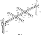
На фиг.1 изображена аксонометрическая проекция предлагаемой стальной каркасной конструкции.Figure 1 shows a perspective view of the proposed steel frame structure.
На фиг.2A изображена аксонометрическая проекция главной балки предлагаемой стальной каркасной конструкции.On figa shows a perspective view of the main beam of the proposed steel frame structure.
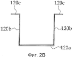
На фиг.2B изображена в сечении центральная часть главной балки предлагаемой стальной каркасной конструкции.On figv depicted in cross section the Central part of the main beam of the proposed steel frame structure.
На фиг.2C изображен в сечении участок соединения главной балки предлагаемой стальной каркасной конструкции.On figs depicted in cross section a section of the connection of the main beam of the proposed steel frame structure.
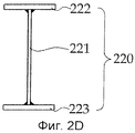
На фиг.2D изображена в сечении концевая часть главной балки предлагаемой стальной каркасной конструкции.On fig.2D shows in cross section the end part of the main beam of the proposed steel frame structure.
На фиг.3 изображена аксонометрическая проекция, на которой показана вспомогательная балка предлагаемой стальной каркасной конструкции.Figure 3 shows a perspective view, which shows the auxiliary beam of the proposed steel frame structure.
На фиг.4 изображена аксонометрическая проекция снизу, иллюстрирующая участок соединения между главной и вспомогательной балкой в предлагаемой стальной каркасной конструкции.Figure 4 shows a perspective view from below, illustrating the portion of the connection between the main and auxiliary beam in the proposed steel frame structure.
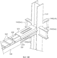
На фиг.5A изображена аксонометрическая проекция, в разобранном виде, иллюстрирующая участок соединения между кронштейном и главной балкой в предлагаемой стальной каркасной конструкции по первому варианту осуществления изобретения.Fig. 5A is an exploded perspective view illustrating a portion of a connection between the bracket and the main beam in the proposed steel frame structure according to the first embodiment of the invention.
На фиг.5B изображена аксонометрическая проекция, иллюстрирующая собранное состояние компонентов фиг.5а.Fig. 5B is a perspective view illustrating the assembled state of the components of Fig. 5a.
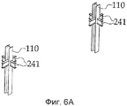
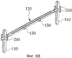
На фиг.6A-6D изображены аксонометрические проекции, иллюстрирующие способ сборки предлагаемой стальной каркасной конструкции по первому варианту осуществления изобретения.On figa-6D depicts a perspective view illustrating a method of assembling the proposed steel frame structure according to the first embodiment of the invention.
На фиг.7A изображена аксонометрическая проекция, в разобранном виде, иллюстрирующая участок соединения между кронштейном и главной балкой в предлагаемой стальной каркасной конструкции по второму варианту осуществления изобретения.Fig. 7A is an exploded perspective view illustrating a portion of the connection between the bracket and the main beam in the proposed steel frame structure according to the second embodiment of the invention.
На фиг.7B изображена аксонометрическая проекция, иллюстрирующая собранное состояние компонентов фиг.7a.7B is a perspective view illustrating the assembled state of the components of FIG. 7a.
На фиг.8A-8D изображены аксонометрические проекции, иллюстрирующие способ сборки предлагаемой стальной каркасной конструкции по второму варианту осуществления изобретения.On figa-8D depicts a perspective view illustrating a method of assembling the proposed steel frame structure according to the second variant embodiment of the invention.
ПРЕДПОЧТИТЕЛЬНЫЕ ВАРИАНТЫ ОСУЩЕСТВЛЕНИЯ ИЗОБРЕТЕНИЯPREFERRED EMBODIMENTS FOR CARRYING OUT THE INVENTION
Далее, со ссылкой на прилагаемые чертежи, приведено подробное описание предлагаемой стальной каркасной конструкции, выполненной по предпочтительным вариантам осуществления изобретения. Нижеследующее описание предлагаемого изобретения лишь иллюстрирует отдельные варианты осуществления изобретения для лучшего раскрытия его сущности, и объем патентных притязаний данными вариантами не ограничивается.Next, with reference to the accompanying drawings, a detailed description of the proposed steel frame structure, made according to the preferred variants of the invention. The following description of the invention only illustrates individual embodiments of the invention to better disclose its essence, and the scope of patent claims by these options is not limited.
На фиг.1 изображена аксонометрическая проекция предлагаемой стальной каркасной конструкции.Figure 1 shows a perspective view of the proposed steel frame structure.
Как показано на фиг.1, предлагаемая стальная каркасная конструкция по первому варианту изобретения содержит колонны 110, главную балку 120, присоединенную между колоннами 110, и вспомогательные балки 130, соединенные с главной балкой 120.As shown in figure 1, the proposed steel frame structure according to the first embodiment of the invention comprises
Поскольку колонны 110 испытывают значительную сжимающую нагрузку, они должны иметь поперечное сечение относительно большого размера. Хотя на чертежах изображены колонны 110 из конструкционной стали H-образного сечения, то есть представляющие собой двутавровые балки, предлагаемое техническое решение ими не ограничивается, и могут быть использованы колонны 110 в виде квадратных труб с характеристиками в сечении, которые не зависят от направления приложенной нагрузки, даже если сложно изготовить участок соединения с главной балкой.Since the
Двутавровые балки используются наиболее широко, поскольку в этом случае легко изготовить соединительную часть между колонной и главной балкой. Поскольку стандартная длина двутавровой балки равна 10 м, двутавровую балку для двух или трех этажей выполняют, по существу, в виде единого изделия. В отличие от квадратных стальных труб, двутавровые балки имеют характеристики в сечении, зависящие от направления приложенной к ним нагрузки, поэтому, как показано на чертеже, стенки двутавровых балок расположены параллельно направлению длинной стороны пролета.I-beams are used most widely, since in this case it is easy to make a connecting part between the column and the main beam. Since the standard length of an I-beam is 10 m, an I-beam for two or three floors is made essentially in the form of a single product. Unlike square steel pipes, I-beams have characteristics in cross section that depend on the direction of the load applied to them, therefore, as shown in the drawing, the walls of I-beams are parallel to the direction of the long side of the span.
Каждая колонна 110 имеет кронштейны 140, присоединенные к ней так, чтобы обеспечивать возможность соединения с главной балкой 120. Если колонна находится в центре плоскости, кронштейны 140 присоединены к обеим полкам и к обеим сторонам стенки колонны, как показано на чертежах. Если колонна расположена в углу, они присоединены к одной полке и к одной стороне стенки колонны. В случае колонны, расположенной на внешней стороне, кронштейны 140 присоединены к обеим полкам и к одной стороне стенки колонны.Each
На фиг.2A изображена аксонометрическая проекция главной балки для использования в предлагаемой стальной каркасной конструкции.On figa shows a perspective view of the main beam for use in the proposed steel frame structure.
Как показано на фиг.2A, главная балка 120, присоединенная между колоннами 110, имеет, по существу, U-образное сечение и содержит центральную стенку 121 и верхнюю полку 122, соединенную с обоими ее концами так, чтобы соединяться с кронштейнами 140. Кроме того, главная балка 120 содержит распорки 160, установленные друг от друга на заданном расстоянии по всей длине верхней поверхности главной балки, и соединители 150 балок, соединенные с главной балкой в местах присоединения к ней вспомогательных балок 130.As shown in FIG. 2A, the
Главная балка 120, которая выполнена путем изгиба тонкого стального листа при комнатной температуре аналогично кронштейну 140, имеет форму с различиями между центральной частью, соответствующей зоне положительного момента, и концевой частью, соответствующей зоне отрицательного момента. Тем самым достигается эффективное использование сечения и легкое соединение с колонной.The
Внутреннее пространство главной балки 120, то есть пространство, ограниченное нижней полкой 120a и боковыми стенками 120b стального листа, заполняется бетоном. Поэтому, для сохранения формы во время сборки и для предотвращения раскрытия боковых стенок 120b при заливке бетона, на главной балке 120 установлены распорки 160. Распорки 160 установлены друг от друга на заданном расстоянии по всей длине главной балки 120, перпендикулярно направлению длины главной балки 120, так чтобы соединять друг с другом опорные полки 120c. Хотя на чертежах показаны L-образные (уголковые) стальные распорки 160, возможны и другие варианты их изготовления. Например, их можно выполнить из элементов, прочность которых предотвращает раскрытие боковых стенок 120b, и с любым подходящим сечением, известным из уровня техники, например, из C-образного стального профиля (швеллеры), Z-образного стального профиля или других подобных элементов. При этом распорки 160 выполняют также функцию шпонок, обеспечивающих соединение различных материалов бетонирования и главной балки 120.The interior of the
Вспомогательные балки 130 присоединены к главной балке 120 перпендикулярно направлению длины главной балки 120. На фиг.1 две вспомогательные балки 130 присоединены к одной стороне главной балки 120, так что к обеим сторонам главной балки 120 присоединены четыре вспомогательные балки 130. Количество вспомогательных балок, присоединенных к главной балке 120, может быть и другим и определяется длиной главной балки 120.The
На фиг.2B изображена в сечении центральная часть главной балки, используемой в предлагаемой стальной каркасной конструкции.On figv depicted in cross section the Central part of the main beam used in the proposed steel frame structure.
Как показано на фиг.2B, центральная часть главной балки 120 состоит из нижней полки 120a, боковых стенок 120b и опорных полок 120c. Боковые стенки 120b выступают перпендикулярно вверх по обоим краям нижней полки 120a, при этом опорные полки 120c выступают наружу из боковых стенок 120b параллельно нижней полке 120a.As shown in FIG. 2B, the central portion of the
На фиг.2C изображен в сечении участок соединения главной балки, используемой в предлагаемой стальной каркасной конструкции.On figs depicts in cross section a section of the connection of the main beam used in the proposed steel frame structure.
На фиг.2D изображена в сечении концевая часть главной балки, используемой в предлагаемой стальной каркасной конструкции.On fig.2D shows in cross section the end part of the main beam used in the proposed steel frame structure.
Как показано на фиг.2C и 2D, участок соединения балки 120 образован соединительным элементом 121a, прикрепленным по центру нижней полки 120a.As shown in FIGS. 2C and 2D, the joining portion of the
Соединительный элемент 121a состоит из центральной стенки 121, а также верхней и нижней полок 122 и 123, выполненных сверху и снизу на центральной стенке 121, и поэтому имеет, по существу, двутавровое сечение. Соединительный элемент 121a установлен на концевой части главной балки 120 таким образом, что концевая часть его нижней полки 123 с одной стороны соединена с верхней поверхностью нижней полки 120a главной балки 120, а концевая часть с другой стороны выставлена наружу.The connecting
На фиг.3 изображена аксонометрическая проекция балки для использования в предлагаемой стальной каркасной конструкции.Figure 3 shows a perspective view of the beam for use in the proposed steel frame structure.
Вспомогательные балки 130 изготовлены аналогично главной балке 120 и имеют ту же форму сечения, что и центральная часть главной балки 120. То есть, как показано на фиг.3, каждая балка 130 содержит нижнюю полку 130a, боковые стенки 130b и опорные полки 130c. Боковые стенки 130b выступают перпендикулярно вверх по обоим краям нижней полки 130а, при этом опорные полки 130c выступают наружу из края боковых стенок 130b параллельно нижней полке 130a. Кроме того, аналогично главной балке 120, по всей длине вспомогательные балки 130 разнесены распорки 160 для предотвращения раскрытия боковых стенок 130b во время сборки и заливки бетона.The
Фиг.4 представляет собой аксонометрическую проекцию снизу, на которой показан участок соединения между главной балкой и вспомогательной балкой в предлагаемой стальной каркасной конструкции.Figure 4 is a perspective view from below, which shows the portion of the connection between the main beam and the auxiliary beam in the proposed steel frame structure.
Вспомогательные балки 130, которые имеют ту же высоту сечения, что и главная балка 120, присоединены к балке 120 посредством соединителей 150 балок. Каждый соединитель 150 балок имеет две боковины 151, расположенные на расстоянии друг от друга, и соединительную пластину 152, соединяющую нижние края боковин 151, и поэтому имеет, по существу, U-образное сечение. Высоты обеих боковин 151 равны высотам боковых стенок 120b, при этом расстояние между боковинами 151 позволяет вставить между ними балку 130. Таким образом, вспомогательные балки 130 вставляются между двумя боковинами 151 соединителей 150 балок и опираются на их соединительные пластины 152. В этом состоянии во вспомогательных балках 130 закреплены болты, что обеспечивает простое и надежное соединение главной балки 120 с балками 130.
При этом в главной балке 120 имеются элементы 180 жесткости, установленные между боковыми стенками 120b в месте соединения с соединителями 150 балок на одной линии с двумя боковинами 151 соединителей 150 балок, что предотвращает изгиб главной балки 120.Moreover, in the
Опишем предлагаемую стальную каркасную конструкцию на примере двух вариантов осуществления с разными типами кронштейна 140.We describe the proposed steel frame structure on the example of two embodiments with different types of
Кронштейн 140, соединяющий колонну 110 и главную балку 120, образован в первом варианте двутавровым кронштейном, который имеет сечение двутавровой балки, и во втором варианте - однотавровым кронштейном (в виде обрезанной "T"), который имеет сечение однотавровой балки, полученной разрезанием стенки двутавровой балки.The
На фиг.5A изображена аксонометрическая проекция, в разобранном состоянии, участка соединения между кронштейном и главной балкой в предлагаемой стальной каркасной конструкции по первому варианту осуществления.On figa shows a perspective view, in a disassembled state, of the connection between the bracket and the main beam in the proposed steel frame structure according to the first embodiment.
На фиг.5B изображена аксонометрическая проекция элементов с фиг.5a в собранном состоянии.On figv depicts a perspective view of the elements of figa in the assembled state.
Как показано на фиг.5A и 5B, кронштейн 140 (141) по первому варианту имеет асимметричное двутавровое или двутавровое сечение той же формы, что и главная балка 120. Кронштейн 140 (141) состоит из верхней полки 141a, стенки 141b, выполненной вертикально по центру верхней полки 141a, и нижней полки 141c, выполненной на нижней стороне стенки 141b параллельно верхней полке 141a. Кронштейн 140 (141) по первому варианту изобретения можно изготовить путем разрезания двутавровой балки или же отдельно.As shown in FIGS. 5A and 5B, the bracket 140 (141) according to the first embodiment has an asymmetric I-beam or I-section of the same shape as the
Главная балка 120 и кронштейн 140 (141) жестко соединены друг с другом посредством накладных пластин. То есть накладные пластины соединяют верхнюю полку 122 соединительного элемента 121a с верхней полкой 141 кронштейна 140 (141), центральную стенку 121 соединительного элемента 121а со стенкой 141b кронштейна 140 (141) и нижнюю полку 123 соединительного элемента 121 с нижней полкой 141 кронштейна 140 (141). При этом соединение между главной балкой 120 и кронштейном 140 (141) выполняется соединительным элементом 121a, посредством отверстий на обеих сторонах стенки 121 соединительного элемента 121а, который не соединен с главной балкой 120, причем центральная стенка 121 и стенка 141b кронштейна 140 (141) соединены накладной пластиной. Затем накладной элемент 170 устанавливается поверх участка соединения между главной балкой 120 и кронштейном 140 (141). Таким образом, в предлагаемом изобретении достигается возможность соединять колонну 110 с главной балкой 120 без помех со стороны боковых стенок 120b главной балки 120, образующих пространство для заливки бетона, как в существующей конструкции участка соединения между двутавровой колонной и вспомогательной балкой.The
Опорные полки 120c главной балки 120, как показано на фиг.5A, отсутствуют на участке соединения между главной балкой 120 и двутавровым кронштейном 140 (141). Поскольку поверхности для опоры плиты настила не предусмотрены, накладной элемент 170 установлен поверх участка соединения между главной балкой 120 и кронштейном 140 (141). Накладной элемент 170 образован верхней пластиной 171, боковинами 172, выступающими перпендикулярно вниз по обоим краям из верхней пластины 171, и нижней планкой 173, выступающей по горизонтали наружу по краю боковин 172. Таким образом, участок соединения между главной балкой 120 и кронштейном 140 (141) закрыт накладным элементом 170.The support flanges 120c of the
Верхняя пластина 171 устанавливается поверх верхних участков верхней полки 122 главной балки 120 и верхней полки 141a кронштейна 140 (141), закрывая участок соединения между главной балкой 120 и кронштейном 140 (141), при этом нижние планки 173 присоединяются к опорным полкам 120с главной балки так, чтобы вместе с опорными полками 120c главной балки 120 обеспечивать поверхности опоры для плиты настила.The
Кроме того, накладной элемент 170 имеет отверстие 175, выполненное в верхней пластине 171 так, чтобы избежать помех со стороны накладных пластин и болтами во время выполнения соединения между верхней полкой 122 главной балки 120 и верхней полкой 141a кронштейна 140 (141).In addition, the
На фиг.7A изображена аксонометрическая проекция, в разобранном состоянии, участка соединения между кронштейном и главной балкой в предлагаемой стальной каркасной конструкции по второму варианту осуществления.On figa shows a perspective view, in a disassembled state, of the connection between the bracket and the main beam in the proposed steel frame structure according to the second embodiment.
На фиг.7B изображена аксонометрическая проекция элементов с фиг.7A в собранном состоянии.On figv shows a perspective view of the elements of figa in the assembled state.
Как показано на фиг.7A и 7B, кронштейн 140 (142) по второму варианту, который имеет асимметричное однотавровое сечение, выполнен путем разрезания стенки двутавровой балки и состоит из полки 142a и стенки 142b. Кронштейн 140 (142) по второму варианту предлагаемого изобретения можно изготовить разрезанием двутавровой балки или отдельно.As shown in FIGS. 7A and 7B, the bracket 140 (142) of the second embodiment, which has an asymmetric single-T-section, is made by cutting the wall of the I-beam and consists of a
Стенка 142b кронштейна 140 (142) прикреплена к колонне 110, при этом его полка 142a прикреплена к концевой части главной балки 120.The
Главная балка 120 и кронштейн 140 (142) жестко соединены друг с другом путем соединения концевой части соединительного элемента 121a главной балки 120 с полкой 142a кронштейна 140 (142). При этом, как указано выше, на участке соединения между главной балкой 120 и кронштейном 140 (142) выполняются отверстия, посредством которых легко выполнить соединение между главной балкой 120 и кронштейном 140 (142). Таким образом, в предлагаемом изобретении достигается возможность выполнять процесс соединения колонны 110 с главной балкой 120 без помех со стороны боковых стенок 120b главной балки 120, образующих пространство для заливки бетона, как в существующей конструкции участка соединения между двутавровой колонной и вспомогательной балкой.The
После соединения накладной элемент 170 устанавливается на участке соединения между главной балкой 120 и кронштейном 140 (142).After joining, the
Опорные полки 120c главной балки 120, как показано на фиг.7A, отсутствуют на участке соединения между главной балкой 120 и двутавровым кронштейном 140 (142). Поскольку поверхности для опоры плиты настила не предусмотрены, накладной элемент 170 установлен поверх участка соединения между главной балкой 120 и кронштейном 140 (142). Накладной элемент 170 образован верхней пластиной 171, боковинами 172, выступающими перпендикулярно вниз по обоим краям из верхней пластины 171, и нижней планкой 173, выступающей по горизонтали наружу по краю боковин 172. Таким образом, участок соединения между главной балкой 120 и кронштейном 140 (142) закрыт накладным элементом 170.The support flanges 120c of the
Верхняя пластина 171 устанавливается поверх верхних участков верхней полки 122 главной балки 120 и полки 142a кронштейна 140 (142), закрывая участок соединения между главной балкой 120 и кронштейном 140 (142), при этом нижние планки 173 присоединяются к опорным полкам 120c главной балки так, чтобы вместе с опорными полками 120c главной балки 120 обеспечивать поверхности опоры для плиты настила.The
Фиг.6A-6D представляют собой аксонометрические проекции, иллюстрирующие способ сборки предлагаемой стальной каркасной конструкции по первому варианту осуществления.Figa-6D are axonometric projections illustrating a method of assembling the proposed steel frame structure according to the first embodiment.
На фиг.8A-8D представляют собой аксонометрические проекции, на которых показан способ сборки предлагаемой стальной каркасной конструкции, выполненной по второму варианту осуществления.On figa-8D are axonometric projections showing a method of assembling the proposed steel frame structure made in the second variant implementation.
В случае выполнения предлагаемой стальной каркасной конструкции согласно описанному выше первому или второму вариантам осуществления, компоненты участка соединения между кронштейном 140 и главной балкой 120 предварительно изготавливают на заводе, привозят на строительную площадку и собирают на месте, используя лишь болтовое соединение, аналогично известному способу сборки стальных несущих конструкций.In the case of the proposed steel frame structure according to the first or second embodiments described above, the components of the connection section between the
Если точнее, колонны 110, главная балка 120, вспомогательные балки 130, кронштейны 140, соединители 150 балок, распорки 160 и накладные элементы 170 изготавливают на заводе. Затем кронштейны 140 приваривают к колоннам 110, а распорки 160, соединители 150 балок и элементы 180 жесткости приваривают к главной балке 120.More specifically, the
Затем их доставляют на строительную площадку и собирают друг с другом. То есть устанавливают вертикально колонны 110 с присоединенными к ним кронштейнами 140 (см. фиг.6A, фиг.8A) и посредством кронштейна 240 присоединяют между колоннами 110 главную балку 120 (см. фиг.6B, фиг.8B). При этом поверх главной балки 120 и кронштейнов 140 устанавливают накладные элементы 170. На последнем этапе к главной балке 120 присоединяют вспомогательные балки 130, используя соединители 150 балок (см. фиг.6C, фиг.8C).Then they are delivered to the construction site and assembled with each other. That is,
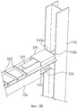
На главную балку 120 и вспомогательные балки 130 стальной каркасной конструкции, выполненной как описано выше, устанавливают плиту 190 настила, которую заливают бетонным покрытием 195 (см. фиг.6D, фиг.8D). Во время заливки бетонного покрытия бетон заполняет главную балку 120 и кронштейны 140. То есть, согласно предлагаемому изобретению, главная балка 120 и вспомогательные балки 130 становятся составной главной балкой и вспомогательной балкой, полученной путем объединения в одно целое стали и бетона.On the
При этом по второму варианту осуществления изобретения колонны 110, которые представляют собой стальные колонны, могут быть выполнены как железобетонные колонны со стальным каркасом, полученные путем покрытия стальной колонны бетоном. В этом случае способ соединения колонн 110 и главной балки 120 аналогичен способу для стальных колонн, однако перед заливкой бетонного покрытия устанавливают стержни колонн. Затем изготавливают формы для литья колонн и выполняют заливку колонн бетоном совместно с заливкой бетонного покрытия.Moreover, according to the second embodiment of the invention, the
Хотя предлагаемое изобретение проиллюстрировано со ссылками на конкретные варианты его осуществления, объем притязаний по данной заявке ограничен лишь прилагаемой формулой изобретения. Очевидно, что специалисты в данной области техники могут создавать измененные или модифицировать варианты изобретения, оставаясь в рамках испрашиваемой правовой охраны и сущности настоящего изобретения.Although the present invention is illustrated with reference to specific options for its implementation, the scope of claims in this application is limited only by the attached claims. Obviously, those skilled in the art can create modified or modify variations of the invention while remaining within the scope of the claimed legal protection and the spirit of the present invention.
Claims (7)
кронштейны, присоединенные к каждой колонне для обеспечения возможности присоединения колонны к главной балке;
при этом главная балка, которая имеет, по существу, U-образное сечение, снабжена соединительным элементом, концевые части которого выступают из обоих ее концов так, чтобы соединяться с указанными кронштейнами, причем соединительный элемент содержит центральную стенку, а также верхнюю и нижнюю полки, выполненные сверху и снизу на центральной стенке, распорками, установленными на заданном расстоянии друга от друга по всей длине ее верхней поверхности, и соединителями балок, присоединенными к ней в местах присоединения вспомогательных балок;
при этом каждая вспомогательная балка имеет ту же высоту сечения, что и главная балка, и содержит нижнюю полку, боковые стенки, выступающие перпендикулярно вверх из обоих краев нижней полки, и опорные полки, выступающие наружу по краю из боковых стенок параллельно нижней полке, причем каждая вспомогательная балка выполнена с возможностью присоединения к главной балке посредством указанных соединителей балок и содержит также распорки, установленные на заданном расстоянии друга от друга по всей длине ее верхней поверхности;
накладной элемент, содержащий верхнюю пластину, размещенную поверх верхних участков верхней полки главной балки и верхней полки кронштейна, боковины, выступающие перпендикулярно вниз из обоих краев верхней пластины, и нижнюю планку, выступающую по горизонтали наружу по краю из боковин на высоте параллельно опорным полкам главной балки, при этом главная балка и вспомогательные балки заполнены бетоном.1. A steel frame structure having columns, a main beam connected between the columns, and auxiliary beams attached to the main beam, the steel frame structure comprising:
brackets attached to each column to allow the column to connect to the main beam;
wherein the main beam, which has a substantially U-shaped cross section, is provided with a connecting element, the end parts of which protrude from both its ends so as to be connected to said arms, the connecting element comprising a central wall and also upper and lower shelves, made from above and below on the central wall, with spacers installed at a given distance from each other along the entire length of its upper surface, and beam connectors attached to it at the points of accession of auxiliary balls ;
wherein each auxiliary beam has the same section height as the main beam, and contains a lower shelf, side walls protruding perpendicular upward from both edges of the lower shelf, and support shelves protruding outward along the edge of the side walls parallel to the lower shelf, each the auxiliary beam is adapted to be connected to the main beam by means of said beam connectors and also comprises spacers installed at a predetermined distance from each other along the entire length of its upper surface;
an overhead element comprising an upper plate placed over the upper portions of the upper shelf of the main beam and the upper bracket shelf, sidewalls protruding perpendicularly downward from both edges of the upper plate, and a lower bar protruding horizontally outward along the edge of the sidewalls at a height parallel to the support flanges of the main beam while the main beam and auxiliary beams are filled with concrete.
Applications Claiming Priority (2)
| Application Number | Priority Date | Filing Date | Title |
|---|---|---|---|
| KR10-2012-0090946 | 2012-08-20 | ||
| KR1020120090946A KR101229194B1 (en) | 2012-08-20 | 2012-08-20 | Steel frame using u-shaped composite beam |
Publications (2)
| Publication Number | Publication Date |
|---|---|
| RU2013138524A RU2013138524A (en) | 2015-02-27 |
| RU2548627C2 true RU2548627C2 (en) | 2015-04-20 |
Family
ID=47898781
Family Applications (1)
| Application Number | Title | Priority Date | Filing Date |
|---|---|---|---|
| RU2013138524/03A RU2548627C2 (en) | 2012-08-20 | 2013-08-20 | Steel frame structure with usage of u-shaped composite beam |
Country Status (2)
| Country | Link |
|---|---|
| KR (1) | KR101229194B1 (en) |
| RU (1) | RU2548627C2 (en) |
Families Citing this family (9)
| Publication number | Priority date | Publication date | Assignee | Title |
|---|---|---|---|---|
| KR101372643B1 (en) * | 2013-08-07 | 2014-03-11 | 장민우 | Formless composite beam and manufacturing method thereof |
| KR101390781B1 (en) | 2013-11-27 | 2014-04-30 | (주)에스엠구조안전진단 | Floor construction method for steel structure using weak-axis semi-rigid connection of h-shape column |
| KR101406583B1 (en) | 2013-12-26 | 2014-06-19 | 주식회사 디알비동일 | U-shaped composite beam |
| KR101814506B1 (en) * | 2016-01-29 | 2018-01-12 | (주)액트파트너 | Steel Built Up Beam And Column-Beam Joint Construction Method Using Thereof |
| KR101855977B1 (en) * | 2016-06-27 | 2018-05-09 | 주식회사 제이에이치이엔지 | Form for construction structure |
| CN106013440A (en) * | 2016-07-12 | 2016-10-12 | 无锡顺达智能自动化工程股份有限公司 | Auxiliary beam supporting structure |
| KR101778994B1 (en) * | 2016-10-21 | 2017-09-18 | (주)씨지스플랜 | Overlapped beam and column-beam connection structure using the beam |
| KR101890274B1 (en) * | 2016-11-29 | 2018-08-22 | (주)엔아이스틸 | Steel Frame Construction Method With Double T-Shaped Joint Structure |
| KR102652453B1 (en) * | 2021-11-22 | 2024-03-29 | 경남대학교 산학협력단 | Composite Beam-Deck Using Deck Plate and Method of Manufacturing the Same |
Citations (4)
| Publication number | Priority date | Publication date | Assignee | Title |
|---|---|---|---|---|
| US4333285A (en) * | 1977-01-20 | 1982-06-08 | Kajima Kensetsu Kabushiki Kaisha | Building structure |
| RU2146320C1 (en) * | 1998-08-19 | 2000-03-10 | Спиридонов Владимир Петрович | Metal framework of multistory building and unit of metal framework |
| KR100860478B1 (en) * | 2007-04-16 | 2008-09-26 | 주식회사 동성진흥 | Beam of steel frame construction |
| KR101152762B1 (en) * | 2011-09-16 | 2012-06-18 | 오지영 | Parking structure |
Family Cites Families (2)
| Publication number | Priority date | Publication date | Assignee | Title |
|---|---|---|---|---|
| KR100787133B1 (en) | 2007-02-15 | 2007-12-21 | 주식회사 하모니구조엔지니어링 | Built up box beam for filling concrete and connection structure thereof |
| KR20110032687A (en) * | 2009-09-23 | 2011-03-30 | 주식회사 세진에스씨엠 | Construction method for joining steel or reinforced steel concrete column and beam with reinforcing end part |
-
2012
- 2012-08-20 KR KR1020120090946A patent/KR101229194B1/en active IP Right Grant
-
2013
- 2013-08-20 RU RU2013138524/03A patent/RU2548627C2/en not_active IP Right Cessation
Patent Citations (4)
| Publication number | Priority date | Publication date | Assignee | Title |
|---|---|---|---|---|
| US4333285A (en) * | 1977-01-20 | 1982-06-08 | Kajima Kensetsu Kabushiki Kaisha | Building structure |
| RU2146320C1 (en) * | 1998-08-19 | 2000-03-10 | Спиридонов Владимир Петрович | Metal framework of multistory building and unit of metal framework |
| KR100860478B1 (en) * | 2007-04-16 | 2008-09-26 | 주식회사 동성진흥 | Beam of steel frame construction |
| KR101152762B1 (en) * | 2011-09-16 | 2012-06-18 | 오지영 | Parking structure |
Also Published As
| Publication number | Publication date |
|---|---|
| KR101229194B1 (en) | 2013-02-01 |
| RU2013138524A (en) | 2015-02-27 |
Similar Documents
| Publication | Publication Date | Title |
|---|---|---|
| RU2548627C2 (en) | Steel frame structure with usage of u-shaped composite beam | |
| US8915042B2 (en) | Steel frame structure using U-shaped composite beam | |
| KR101208207B1 (en) | Steel frame using u-shaped composite beam | |
| US9518401B2 (en) | Open web composite shear connector construction | |
| CN108005410B (en) | Assembled steel-concrete combined structure residential system and construction method thereof | |
| CN108005265B (en) | Multilayer prefabricated steel reinforced concrete shear wall structure and preparation and construction methods thereof | |
| KR101406583B1 (en) | U-shaped composite beam | |
| US20120304563A1 (en) | Space light steel frame concrete building and construction method thereof | |
| KR101456391B1 (en) | Formed steel beam with holes and structure of composite floor | |
| JP2019526004A (en) | Precast concrete formwork, floor system, and construction method | |
| KR101191502B1 (en) | Structure system using bar truss integrated asymmetry h-beam and end beam | |
| KR101547540B1 (en) | Hybrid beam having different type flange | |
| KR101129502B1 (en) | Synthetic girder of i type | |
| KR20050054407A (en) | Steel concrete structure using angle shapes | |
| JP5869717B1 (en) | Existing concrete structure reinforcement structure | |
| CN109138220B (en) | Fiber cement board composite assembled framework, wall body component and assembled steel-concrete shear wall | |
| KR101407816B1 (en) | structure system using bar truss integrated asymmetry H-beam | |
| KR200469319Y1 (en) | Construction structure for joining steel or reinforced steel concrete column and beam with reinforcing end part | |
| KR101373262B1 (en) | Connecting plate crossing type concrete filled tubular column | |
| WO2015051551A1 (en) | Building and construction method thereof | |
| CN110344503B (en) | Local superimposed sheet and combination wall post connected node structure | |
| KR101346671B1 (en) | The pin connection structure using the spacer in the junction of pc beam and vertical member | |
| KR101148546B1 (en) | Steel built up beam for longspan structure and steel frame using the same | |
| KR101202296B1 (en) | Pre-fabricated mold | |
| KR101202300B1 (en) | Product method of pre-fabricated mold |
Legal Events
| Date | Code | Title | Description |
|---|---|---|---|
| TK4A | Correction to the publication in the bulletin (patent) |
Free format text: AMENDMENT TO CHAPTER -FG4A- IN JOURNAL: 11-2015 |
|
| MM4A | The patent is invalid due to non-payment of fees |
Effective date: 20180821 |