RU2546671C2 - Motor control device - Google Patents
Motor control device Download PDFInfo
- Publication number
- RU2546671C2 RU2546671C2 RU2013139315/07A RU2013139315A RU2546671C2 RU 2546671 C2 RU2546671 C2 RU 2546671C2 RU 2013139315/07 A RU2013139315/07 A RU 2013139315/07A RU 2013139315 A RU2013139315 A RU 2013139315A RU 2546671 C2 RU2546671 C2 RU 2546671C2
- Authority
- RU
- Russia
- Prior art keywords
- motor
- engine
- voltage
- frequency
- current
- Prior art date
Links
- 230000000694 effects Effects 0.000 abstract description 3
- 230000015572 biosynthetic process Effects 0.000 abstract description 2
- 230000005611 electricity Effects 0.000 abstract 1
- 238000007493 shaping process Methods 0.000 abstract 1
- 239000000126 substance Substances 0.000 abstract 1
- 230000014509 gene expression Effects 0.000 description 84
- 238000010586 diagram Methods 0.000 description 33
- 238000000034 method Methods 0.000 description 25
- 238000004804 winding Methods 0.000 description 21
- 230000001360 synchronised effect Effects 0.000 description 15
- 238000006243 chemical reaction Methods 0.000 description 7
- 238000001514 detection method Methods 0.000 description 6
- 230000006698 induction Effects 0.000 description 4
- 239000000463 material Substances 0.000 description 4
- 230000007423 decrease Effects 0.000 description 3
- 230000005540 biological transmission Effects 0.000 description 1
- 238000005516 engineering process Methods 0.000 description 1
- 239000011159 matrix material Substances 0.000 description 1
- 230000010363 phase shift Effects 0.000 description 1
- 239000004065 semiconductor Substances 0.000 description 1
Images


Classifications
-
- H—ELECTRICITY
- H02—GENERATION; CONVERSION OR DISTRIBUTION OF ELECTRIC POWER
- H02P—CONTROL OR REGULATION OF ELECTRIC MOTORS, ELECTRIC GENERATORS OR DYNAMO-ELECTRIC CONVERTERS; CONTROLLING TRANSFORMERS, REACTORS OR CHOKE COILS
- H02P31/00—Arrangements for regulating or controlling electric motors not provided for in groups H02P1/00 - H02P5/00, H02P7/00 or H02P21/00 - H02P29/00
-
- H—ELECTRICITY
- H02—GENERATION; CONVERSION OR DISTRIBUTION OF ELECTRIC POWER
- H02P—CONTROL OR REGULATION OF ELECTRIC MOTORS, ELECTRIC GENERATORS OR DYNAMO-ELECTRIC CONVERTERS; CONTROLLING TRANSFORMERS, REACTORS OR CHOKE COILS
- H02P23/00—Arrangements or methods for the control of AC motors characterised by a control method other than vector control
- H02P23/14—Estimation or adaptation of motor parameters, e.g. rotor time constant, flux, speed, current or voltage
-
- H—ELECTRICITY
- H02—GENERATION; CONVERSION OR DISTRIBUTION OF ELECTRIC POWER
- H02P—CONTROL OR REGULATION OF ELECTRIC MOTORS, ELECTRIC GENERATORS OR DYNAMO-ELECTRIC CONVERTERS; CONTROLLING TRANSFORMERS, REACTORS OR CHOKE COILS
- H02P23/00—Arrangements or methods for the control of AC motors characterised by a control method other than vector control
- H02P23/22—Controlling the speed digitally using a reference oscillator, a speed proportional pulse rate feedback and a digital comparator
-
- H—ELECTRICITY
- H02—GENERATION; CONVERSION OR DISTRIBUTION OF ELECTRIC POWER
- H02P—CONTROL OR REGULATION OF ELECTRIC MOTORS, ELECTRIC GENERATORS OR DYNAMO-ELECTRIC CONVERTERS; CONTROLLING TRANSFORMERS, REACTORS OR CHOKE COILS
- H02P27/00—Arrangements or methods for the control of AC motors characterised by the kind of supply voltage
- H02P27/04—Arrangements or methods for the control of AC motors characterised by the kind of supply voltage using variable-frequency supply voltage, e.g. inverter or converter supply voltage
- H02P27/06—Arrangements or methods for the control of AC motors characterised by the kind of supply voltage using variable-frequency supply voltage, e.g. inverter or converter supply voltage using dc to ac converters or inverters
- H02P27/08—Arrangements or methods for the control of AC motors characterised by the kind of supply voltage using variable-frequency supply voltage, e.g. inverter or converter supply voltage using dc to ac converters or inverters with pulse width modulation
- H02P27/085—Arrangements or methods for the control of AC motors characterised by the kind of supply voltage using variable-frequency supply voltage, e.g. inverter or converter supply voltage using dc to ac converters or inverters with pulse width modulation wherein the PWM mode is adapted on the running conditions of the motor, e.g. the switching frequency
Abstract
Description
ОБЛАСТЬ ТЕХНИКИFIELD OF TECHNOLOGY
Настоящее изобретение относится к устройству управления для двигателя, содержащего средство для определения типа двигателя.The present invention relates to a control device for an engine comprising means for determining an engine type.
УРОВЕНЬ ТЕХНИКИBACKGROUND
Чтобы приводить в действие двигатель, такой как асинхронный двигатель или синхронный двигатель, необходимо узнать тип двигателя заранее, перед приведением в действие двигателя, так как способ приведения в действие различается в зависимости от типа двигателя. Следовательно, традиционно, пользователь узнает тип двигателя заранее и выбирает устройство управления и способ управления в соответствии с типом двигателя. Однако может быть сложно распознать типы некоторых двигателей из их внешнего вида. Таким образом, пользователь не всегда может распознать тип двигателя.In order to drive a motor, such as an induction motor or a synchronous motor, it is necessary to know the type of motor in advance, before driving the motor, since the method of driving varies depending on the type of motor. Therefore, traditionally, the user recognizes the type of engine in advance and selects a control device and a control method in accordance with the type of engine. However, it can be difficult to recognize the types of some engines from their appearance. Thus, the user cannot always recognize the type of engine.
Чтобы решить вышеприведенную проблему, предлагается патентный документ 1. Способ согласно патентному документу 1 определяет тип двигателя посредством использования того факта, что степень насыщения двигателя различается в зависимости от типа двигателя.To solve the above problem,
СПИСОК БИБЛИОГРАФИЧЕСКИХ ССЫЛОКLIST OF BIBLIOGRAPHIC REFERENCES
ПАТЕНТНЫЙ ДОКУМЕНТPATENT DOCUMENT
Патентный документ 1: Публикация выложенного патента Японии № 2002-095289.Patent Document 1: Japanese Patent Laid-Open Publication No. 2002-095289.
СУЩНОСТЬ ИЗОБРЕТЕНИЯSUMMARY OF THE INVENTION
ЗАДАЧИ, КОТОРЫЕ ДОЛЖНЫ БЫТЬ РЕШЕНЫ ИЗОБРЕТЕНИЕМPROBLEMS THAT SHOULD BE SOLVED BY THE INVENTION
Способ по патентному документу 1 определяет тип двигателя на основании степени насыщения двигателя. Например, в случае асинхронного двигателя, тип двигателя определяется посредством использования того факта, что степень насыщения двигателя постоянна независимо от положения ротора двигателя, а в случае синхронного двигателя (синхронного двигателя со встроенным магнитом, синхронного двигателя с поверхностным магнитом или синхронного реактивного двигателя) тип двигателя определяется посредством использования того факта, что степень насыщения двигателя зависит от положения ротора. Однако в синхронном двигателе, сконструированном таким образом, что магнитное насыщение едва ли наступает, изменение степени насыщения в зависимости от положения ротора невелико, поэтому может быть сложно отличить синхронный двигатель от асинхронного двигателя. То есть, так как степень насыщения может быть подвергнута влиянию конструкции двигателя, помимо типа двигателя, может быть сложно определить тип двигателя посредством способа определения типа двигателя из степени насыщения.The method of
Настоящее изобретение было сделано, чтобы решить вышеприведенную проблему, и задачей настоящего изобретения является предоставление устройства управления двигателем, способного определять тип двигателя посредством способа, менее подверженного факторам, отличным от типа двигателя, таким как конструкция двигателя, таким образом улучшая точность определения.The present invention was made to solve the above problem, and an object of the present invention is to provide an engine control device capable of determining an engine type by a method less susceptible to factors other than the engine type, such as engine design, thereby improving the accuracy of determination.
РЕШЕНИЕ ЗАДАЧИTHE SOLUTION OF THE PROBLEM
Устройство управления двигателем согласно настоящему изобретению включает в себя: секцию установки команд частоты для вывода множества команд частоты; секцию формирования команд напряжения переменного тока (AC) для формирования и вывода команды напряжения AC на основании каждой из команд частоты; секцию приложения напряжения для приложения напряжения к двигателю на основании команды напряжения AC; секцию определения тока для определения тока двигателя, протекающего в двигателе; и секцию определения типа для определения типа двигателя на основании передаточной характеристики двигателя, рассчитанной из тока двигателя, команды напряжения AC и команды частоты.The engine control device according to the present invention includes: a frequency command setting section for outputting a plurality of frequency commands; an AC voltage command generation section for generating and outputting an AC voltage command based on each of the frequency commands; a voltage application section for applying voltage to the engine based on an AC voltage command; a current detection section for detecting a current of the motor flowing in the engine; and a type determination section for determining a motor type based on a motor transfer characteristic calculated from a motor current, an AC voltage command and a frequency command.
РЕЗУЛЬТАТ ИЗОБРЕТЕНИЯSUMMARY OF THE INVENTION
Устройство управления двигателем согласно настоящему изобретению включает в себя: секцию установки команд частоты для вывода множества команд частоты; секцию формирования команд напряжения переменного тока (AC) для формирования и вывода команды напряжения AC на основании каждой из команд частоты; секцию приложения напряжения для приложения напряжения к двигателю на основании команды напряжения AC; секцию определения тока для определения тока двигателя, протекающего в двигателе; и секцию определения типа для определения типа двигателя на основании передаточной характеристики двигателя, рассчитанной из тока двигателя, команды напряжения AC и команды частоты. Следовательно, устройство управления двигателем согласно настоящему изобретению может определять тип двигателя на основании передаточной характеристики двигателя, менее подверженной фактору, отличному от типа двигателя, такому как конструкция двигателя, таким образом, улучшая точность определения типа двигателя.The engine control device according to the present invention includes: a frequency command setting section for outputting a plurality of frequency commands; an AC voltage command generation section for generating and outputting an AC voltage command based on each of the frequency commands; a voltage application section for applying voltage to the engine based on an AC voltage command; a current detection section for detecting a current of the motor flowing in the engine; and a type determination section for determining a motor type based on a motor transfer characteristic calculated from a motor current, an AC voltage command and a frequency command. Therefore, the engine control device according to the present invention can determine an engine type based on an engine transfer characteristic less susceptible to a factor other than the engine type, such as engine design, thereby improving the accuracy of determining the engine type.
КРАТКОЕ ОПИСАНИЕ ЧЕРТЕЖЕЙBRIEF DESCRIPTION OF THE DRAWINGS
Фиг. 1 - диаграмма конфигурации согласно устройству управления двигателем варианта осуществления 1 настоящего изобретения.FIG. 1 is a configuration diagram according to an engine control apparatus of
Фиг. 2 - подробная диаграмма конфигурации согласно устройству управления двигателем варианта осуществления 1 настоящего изобретения.FIG. 2 is a detailed configuration diagram according to an engine control apparatus of
Фиг. 3 - диаграмма объяснения функций согласно устройству управления двигателем варианта осуществления 1 настоящего изобретения.FIG. 3 is a function explanation diagram according to an engine control apparatus of
Фиг. 4 - диаграмма объяснения функций согласно устройству управления двигателем варианта осуществления 1 настоящего изобретения.FIG. 4 is a diagram for explaining functions according to an engine control apparatus of
Фиг. 5 - блок-схема последовательности операций для объяснения процесса согласно устройству управления двигателем варианта осуществления 1 настоящего изобретения.FIG. 5 is a flowchart for explaining a process according to an engine control apparatus of
Фиг. 6 - подробная диаграмма конфигурации согласно устройству управления двигателем варианта осуществления 1 настоящего изобретения.FIG. 6 is a detailed configuration diagram according to an engine control apparatus of
Фиг. 7 - диаграмма объяснения функций согласно устройству управления двигателем варианта осуществления 1 настоящего изобретения.FIG. 7 is a diagram for explaining functions according to an engine control apparatus of
Фиг. 8 - диаграмма объяснения функций согласно устройству управления двигателем варианта осуществления 1 настоящего изобретения.FIG. 8 is a function explanation diagram according to an engine control apparatus of
Фиг. 9 - другая диаграмма конфигурации согласно устройству управления двигателем варианта осуществления 1 настоящего изобретения.FIG. 9 is another configuration diagram according to an engine control apparatus of
Фиг. 10 - другая подробная диаграмма конфигурации согласно устройству управления двигателем варианта осуществления 1 настоящего изобретения.FIG. 10 is another detailed configuration diagram according to an engine control apparatus of
Фиг. 11 - диаграмма конфигурации согласно устройству управления двигателем варианта осуществления 2 настоящего изобретения.FIG. 11 is a configuration diagram according to an engine control device of
Фиг. 12 - блок-схема последовательности операций для объяснения процесса согласно устройству управления двигателем варианта осуществления 2 настоящего изобретения.FIG. 12 is a flowchart for explaining a process according to an engine control device of
Фиг. 13 - диаграмма конфигурации согласно устройству управления двигателем варианта осуществления 2 настоящего изобретения.FIG. 13 is a configuration diagram according to an engine control apparatus of
Фиг. 14 - диаграмма эквивалентной схемы двигателя согласно устройству управления двигателем варианта осуществления 2 настоящего изобретения.FIG. 14 is an equivalent circuit diagram of an engine according to an engine control device of
Фиг. 15 - подробная диаграмма конфигурации согласно устройству управления двигателем варианта осуществления 2 настоящего изобретения.FIG. 15 is a detailed configuration diagram according to an engine control device of
ОПИСАНИЕ ВАРИАНТОВ ОСУЩЕСТВЛЕНИЯDESCRIPTION OF EMBODIMENTS
Вариант осуществления 1
В дальнейшем в материалах настоящей заявки, вариант осуществления 1 настоящего изобретения будет описан со ссылкой на чертежи. Фиг. 1 - диаграмма, показывающая аппаратную конфигурацию устройства 1 управления двигателем согласно варианту осуществления 1 настоящего изобретения, фиг. 2 - подробная диаграмма конфигурации, фиг. 3 и 4 - диаграммы объяснения функций, фиг. 5 - блок-схема последовательности операций для объяснения процесса, фиг. 6 - подробная диаграмма конфигурации, фиг. 7 и 8 - диаграммы объяснения функций. Вдобавок, фиг. 9 и 10 - диаграммы конфигурации, показывающие изменения согласно варианту осуществления 1 настоящего изобретения.Hereinafter, in the materials of the present application,
В дальнейшем в материалах настоящей заявки, устройство 1 управления двигателем согласно варианту осуществления 1 настоящего изобретения будет описано на основании фиг. 1.Hereinafter, in the present application, the
В варианте осуществления 1, двигатель 2, приводимый в действие устройством 1 управления двигателем, является AC двигателем. Устройство 1 управления двигателем включает в себя: секцию 4 приложения напряжения для приложения напряжения к двигателю 2; секцию 3 определения тока для определения тока двигателя, протекающего между секцией 4 приложения напряжения и двигателем 2; секцию 5 формирования команд напряжения AC для передачи команды напряжения AC для секции 4 приложения напряжения; секцию 6 установки команд частоты для передачи команды частоты f для секции 5 формирования команд напряжения AC; и секцию 7 определения типа для вычисления передаточной характеристики двигателя из команды напряжения AC, команды частоты и тока двигателя, и определения типа двигателя.In
На фиг. 1 секция 3 определения тока определяет u-фазный ток и v-фазный ток. Однако любая комбинация двух фаз, отличная от комбинации u-фазы и v-фазы, может быть определена. Вместо этого, могут быть определены u-фаза, v-фаза и w-фаза.In FIG. 1
Секция 4 приложения напряжения является полупроводниковым силовым преобразователем и прикладывает напряжение AC к двигателю 2 на основании команды напряжения AC, выведенной секцией 5 формирования команд напряжения AC.The
Фиг. 2 - подробная диаграмма конфигурации секции 5 формирования команд напряжения AC.FIG. 2 is a detailed configuration diagram of an AC voltage
Умножитель 51 умножает команду частоты f(n) на 2π, чтобы получить команду угловой частоты ωn. Блок 52 вычисления тригонометрической функции выводит косинусоидную функцию cos(ωn·t) на основании команды угловой частоты ωn. Здесь, тригонометрическая функция, выводимая блоком 52 вычисления тригонометрической функции, может являться либо косинусоидной функцией cos(ωn·t), либо синусоидальной функцией sin(ωn·t). В варианте осуществления 1, ниже будет описан случай вывода косинусоидной функции cos(ωn·t).Multiplier 51 multiplies the frequency command f (n) by 2π to obtain the angular frequency command ωn. The trigonometric
Умножитель 53 умножает косинусоидную функцию cos(ωn·t), выводимую блоком 52 вычисления тригонометрической функции, на амплитуду команды напряжения Vref, которая является заданной постоянной величиной, тем самым выводя Vref·cos(ωn·t). Двухфазный/трехфазный преобразователь 54 выполняет двухфазное/трехфазное преобразование для команды напряжения по оси α Vα и команды напряжения по оси β Vβ, которые являются командами напряжения по двум осям в покое, в соответствии с выражением (1), тем самым выводя команды напряжения AC Vu*, Vv*, и Vw*.The multiplier 53 multiplies the cosine function cos (ωn · t) output by the trigonometric
[Выражение 1][Expression 1]

В варианте осуществления 1, Vα равняется Vref·cos(ωn·t), выводимому умножителем 53, а Vβ=0 задано. Следовательно, команда напряжения AC, выводимая секцией 5 формирования команд напряжения AC, является переменным напряжением, в котором направление вектора напряжения изменяется между двумя направлениями.In
Отметим, что может быть задана команда напряжения AC, рассчитанная посредством выражения (1), используя Vβ=Vref·cos(ωn·t) и Vα=0.Note that the AC voltage command can be given, calculated by means of expression (1), using Vβ = Vref · cos (ωn · t) and Vα = 0.
Вдобавок, Vα и Vβ могут быть установлены с тем, чтобы получить переменное напряжение, в котором направление вектора напряжения изменяется среди трех и более направлений. В варианте осуществления 1 будет описан случай задаваемых Vα и Vβ для получения переменного напряжения.In addition, Vα and Vβ can be set so as to obtain an alternating voltage in which the direction of the voltage vector varies among three or more directions. In
В дальнейшем, в качестве используемого в настоящем изобретении, переменное напряжение (ток) определяется как напряжение (ток), в котором вектор напряжения (тока) меняется между двумя направлениями, например, 0 градусов и 180 градусов.Hereinafter, as used in the present invention, an alternating voltage (current) is defined as a voltage (current) in which the voltage (current) vector changes between two directions, for example, 0 degrees and 180 degrees.
Со ссылкой на диаграмму объяснения функций на фиг. 3 будет описана функция секции 6 установки команд частоты.With reference to the function explanation diagram in FIG. 3, the function of the frequency
Секция 6 установки команд частоты устанавливает и выводит множество различных команд частоты. В варианте осуществления 1, как показано на фиг. 3, секция 6 установки команд частоты устанавливает, в качестве команды частоты f(n), n различных команд частоты от f(1) до f(n), и последовательно выводит их в соответствии со значением счетчика n.The frequency
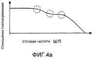
Далее, со ссылкой на диаграмму объяснения функций на фиг. 4, будет подробно описано функционирование секции 7 определения типа.Next, with reference to the function explanation diagram in FIG. 4, the operation of the
Секция 7 определения типа рассчитывает передаточную характеристику из переменного напряжения двигателя 2 к току двигателя посредством использования токов двигателя iu и iv, команд напряжения AC Vu*, Vv*, и Vw*, и команды частоты f(n), и определяет тип двигателя посредством передаточной характеристики.The
А именно, тип двигателя определяется в зависимости от двигателя, содержащего цепь (в дальнейшем в материалах настоящей заявки указываемую как вторичная цепь), в которой ток течет в роторе, такого как асинхронный двигатель или синхронный двигатель, и двигателя, не содержащего вторичную цепь, такого как синхронный двигатель с постоянным магнитом или синхронный реактивный двигатель.Namely, the type of motor is determined depending on the motor containing the circuit (hereinafter referred to as the secondary circuit), in which current flows in the rotor, such as an induction motor or synchronous motor, and a motor that does not contain a secondary circuit, such like a permanent magnet synchronous motor or a synchronous jet engine.
Фиг. 4(a) показывает пример передаточной характеристики асинхронного двигателя, а фиг. 4(b) показывает пример передаточной характеристики синхронного двигателя с постоянным магнитом. Отметим, что угловая частота горизонтальной оси на фиг. 4 обозначена, как десятичный логарифм, преобразованный из угловой частоты.FIG. 4 (a) shows an example of a transfer characteristic of an induction motor, and FIG. 4 (b) shows an example of a transfer characteristic of a permanent magnet synchronous motor. Note that the angular frequency of the horizontal axis in FIG. 4 is denoted as a decimal logarithm converted from angular frequency.
В варианте осуществления 1, как показано на фиг. 4, частотная характеристика (в дальнейшем в материалах настоящей заявки указываемая как амплитудная характеристика) отношения (усиления) между амплитудой переменного напряжения и амплитудой тока двигателя, получаемого посредством деления амплитуды тока двигателя на амплитуду переменного напряжения, используется в качестве передаточной характеристики.In
Как показано на фиг. 4, амплитудная характеристика различается между двигателем (асинхронным двигателем), содержащим вторичную цепь, и двигателем (двигателем с постоянным магнитом), не содержащим вторичную цепь.As shown in FIG. 4, the amplitude characteristic differs between a motor (asynchronous motor) containing a secondary circuit and a motor (permanent magnet motor) not containing a secondary circuit.
А именно, в двигателе, содержащем вторичную цепь, показанном на фиг. 4(a), так как двигатель содержит вторичную цепь, передаточная функция двигателя является системой второго порядка. Следовательно, имеется три точки (обозначенные штрихованными кругами), в которых наклон усиления изменяется на амплитудной характеристике. С другой стороны, в двигателе, не содержащем вторичную цепь, показанном на фиг. 4(b), так как его передаточная функция является системой первого порядка, имеется только одна точка, в которой наклон усиления изменяется.Namely, in the engine containing the secondary circuit shown in FIG. 4 (a), since the engine contains a secondary circuit, the transfer function of the engine is a second-order system. Therefore, there are three points (indicated by dashed circles) at which the gain slope changes on the amplitude response. On the other hand, in the secondary circuit-free motor shown in FIG. 4 (b), since its transfer function is a first-order system, there is only one point at which the gain slope changes.
Благодаря такому признаку, если имеется одна точка, в которой наклон усиления изменяется на амплитудной характеристике, двигатель может быть определен как двигатель, не содержащий вторичную цепь, и если имеется две или более точки, в которых наклон усиления изменяется, двигатель может быть определен как двигатель, содержащий вторичную цепь.Due to this feature, if there is one point at which the gain slope changes on the amplitude characteristic, the engine can be defined as an engine that does not contain a secondary circuit, and if there are two or more points at which the gain slope changes, the engine can be defined as a motor containing a secondary circuit.
Соответственно, в варианте осуществления 1, рассчитывается наклон усиления, и тип двигателя определяется на основании наклона усиления.Accordingly, in
В дальнейшем в материалах настоящей заявки будет описан конкретный способ для определения.In the future, the materials of this application will describe a specific method for determining.
Фиг. 5 - блок-схема последовательности операций для объяснения процесса определения типа двигателя согласно устройству управления двигателем варианта осуществления 1.FIG. 5 is a flowchart for explaining an engine type determination process according to an engine control device of
Когда процесс начинается (S51), устанавливаются начальное значение n=1 и индикатор определения F=0, описанные ниже (S52). Далее, в соответствии со значением счетчика n (начальное значение =1), устанавливается команда частоты f(n) (S53).When the process starts (S51), the initial value n = 1 and the determination indicator F = 0 are set as described below (S52). Next, in accordance with the counter value n (initial value = 1), the frequency command f (n) is set (S53).
Отметим, что команда частоты f при значении счетчика n обозначается f(n), и значение команды частоты, соответствующее каждому значению счетчика, устанавливается заранее.Note that the frequency command f at the counter value n is denoted by f (n), and the frequency command value corresponding to each counter value is set in advance.
Затем, переменное напряжение при команде частоты f(n) прикладывается к двигателю (S54). Как описано выше, переменное напряжение формируется секцией 4 приложения напряжения на основании команды напряжения AC, выводимой из секции 5 формирования команд напряжения AC, и затем прикладывается к двигателю 2. Когда переменное напряжение прикладывается, переменный ток течет в двигателе 2, и переменный ток определяется секцией 3 определения тока (S55).Then, an alternating voltage with a frequency command f (n) is applied to the motor (S54). As described above, the alternating voltage is generated by the
Затем рассчитывается индикатор амплитуды переменного тока (S56), и рассчитывается усиление G(n), которое является отношением между амплитудой переменного тока и амплитудой переменного напряжения при значении счетчика n (S57). Затем рассчитывается наклон Ggd(n) усиления (S58).Then, an alternating current amplitude indicator (S56) is calculated, and a gain G (n) is calculated, which is the ratio between the alternating current amplitude and the amplitude of the alternating voltage at the counter value n (S57). Then, the gain slope Ggd (n) is calculated (S58).
Затем рассчитывается индикатор определения F (S59), описываемый подробно позже.Then, the determination indicator F (S59) is calculated, described in detail later.
Если значение счетчика n равняется или меньше, чем максимальное значение счетчика N_end, установленное заранее (S60), значение счетчика устанавливается на n+1 посредством прибавления 1 к значению счетчика n (S61). После этого этапы с S53 по S60 повторяются, пока значение счетчика n не станет больше, чем максимальное значение N_end.If the counter value n is equal to or less than the maximum counter value N_end set in advance (S60), the counter value is set to n + 1 by adding 1 to the counter value n (S61). After this, steps S53 to S60 are repeated until the counter value n becomes greater than the maximum value N_end.
Если значение счетчика n больше, чем максимальное значение счетчика, определяют, является ли двигатель двигателем, содержащим вторичную цепь или двигателем, не содержащим вторичную цепь, на основании значения индикатора определения F (с S62 по S64), и затем процесс завершается (S65).If the counter value n is greater than the maximum counter value, it is determined whether the engine is a motor containing a secondary circuit or a motor not containing a secondary circuit based on the value of the determination indicator F (S62 to S64), and then the process ends (S65).
Фиг. 6 - подробная диаграмма конфигурации секции 7 определения типа, в которой выполняется вышеупомянутый расчет индикатора амплитуды переменного тока, амплитуды Vref переменного напряжения, усиления G, и наклона Ggd усиления, и вышеупомянутое определение типа двигателя.FIG. 6 is a detailed configuration diagram of a
Блок 71 вычисления амплитуды тока рассчитывает и выводит индикатор амплитуды переменного тока Iamp посредством выражения (2), используя токи двигателя iu и iv, выводимые секцией 3 определения тока.The current
[Выражение 2][Expression 2]

Блок 72 вычисления амплитуды напряжения рассчитывает амплитуду Vref команды напряжения AC посредством выражения (3), используя Vu*, Vv*, и Vw*, выводимые секцией 5 формирования команды напряжения AC.The voltage
[Выражение 3][Expression 3]

Делитель 73 делит индикатор амплитуды переменного тока на амплитуду Vref команды напряжения AC, тем самым рассчитывая и выводя усиление G. Блок 75 задержки выводит усиление G(n-1), полученное при значении счетчика n-1, то есть на один подсчет перед настоящим значением счетчика.The
Сумматор-вычитатель 74 вычитает усиление G(n-1) на один подсчет раньше, выводимый блоком 75 задержки, из усиления G(n), выводимого делителем 73, тем самым выводя разницу ΔG(n) усиления. Умножитель 76 умножает команду частоты f(n), выводимую секцией 6 установки команд частоты, на 2π, тем самым выводя угловую частоту ωn. Блок 77 преобразования десятичного логарифма преобразовывает угловую частоту ωn, выводимую умножителем 76, в значение десятичного логарифма ωn' угловой частоты, посредством выражения (4).The adder-
[Выражение 4][Expression 4]
![]()
![]()
Блок 79 задержки выводит значение десятичного логарифма ωn-1' угловой частоты, полученное при значении счетчика n-1, то есть на один подсчет перед настоящим значением счетчика. Сумматор-вычитатель 78 вычитает значение десятичного логарифма ωn-1' угловой частоты на один подсчет раньше, выводимое блоком 79 задержки, из значения десятичного логарифма ωn' угловой частоты, выводимого блоком 77 преобразования десятичного логарифма, таким образом, выводя разницу Δωn' значения десятичного логарифма угловой частоты.
Делитель 80 делит разницу ΔG(n) усиления, выводимую сумматором-вычитателем 74, на разницу Δωn' значения десятичного логарифма угловой частоты, выводимую сумматором-вычитателем 78, таким образом, рассчитывая наклон Ggd(n) усиления.The
Далее, со ссылкой на диаграммы объяснения функций на фиг. 7 и 8, будет описано функционирование блока 81 вычисления индикатора определения на фиг. 6, то есть функционирование вычисления индикатора определения F (S59) блок-схемы последовательности операций на фиг. 5.Next, with reference to function explanation diagrams in FIG. 7 and 8, the operation of the determination
Блок 81 вычисления индикатора определения устанавливает и выводит индикатор определения F на основании наклона Ggd(n) усиления, выводимого делителем 80.The determination
Фиг. 7 показывает пример усиления G(n) и наклона Ggd(n) усиления относительно угловой частоты ωn, когда переменное напряжение при частотах с f(1) по f(n) последовательно прикладывается к двигателю, не содержащему вторичную цепь.FIG. 7 shows an example of the gain G (n) and the slope Ggd (n) of the gain with respect to the angular frequency ωn, when an alternating voltage at frequencies f (1) through f (n) is successively applied to a motor that does not contain a secondary circuit.
Фиг. 8 показывает пример усиления G(n) и наклона Ggd(n) усиления относительно угловой частоты ωn, когда переменное напряжение при частотах с f(1) по f(n) последовательно прикладывается к двигателю, содержащему вторичную цепь.FIG. 8 shows an example of the gain G (n) and the slope Ggd (n) of the gain with respect to the angular frequency ωn, when an alternating voltage at frequencies f (1) through f (n) is sequentially applied to a motor containing a secondary circuit.
Как показано на фиг. 7, в двигателе, не содержащем вторичную цепь, передаточная функция является системой первого порядка, и имеется одна точка, в которой наклон усиления изменяется на амплитудной характеристике. При низких угловых частотах (с ω1 по ω6 на фиг. 7) наклон Ggd усиления близок к нулю. При угловых частотах (с ω7 по ω15 на фиг. 7), более высоких, чем вокруг точки, в которой наклон усиления изменяется, чем выше угловая частота, тем меньше наклон Ggd усиления.As shown in FIG. 7, in an engine not containing a secondary circuit, the transfer function is a first-order system, and there is one point at which the gain slope changes on the amplitude characteristic. At low angular frequencies (from ω1 to ω6 in Fig. 7), the gain slope Ggd is close to zero. At angular frequencies (from ω7 to ω15 in Fig. 7), higher than around the point at which the gain slope changes, the higher the angular frequency, the smaller the gain slope Ggd.
С другой стороны, в двигателе, содержащем вторичную цепь, на фиг. 8, передаточная функция является системой второго порядка, и имеются три точки, в которых наклон усиления изменяется на амплитудной характеристике. При низких угловых частотах (с ω1 по ω4 на фиг. 8) наклон Ggd усиления близок к нулю.On the other hand, in the engine containing the secondary circuit, in FIG. 8, the transfer function is a second-order system, and there are three points at which the gain slope changes on the amplitude characteristic. At low angular frequencies (from ω1 to ω4 in Fig. 8), the gain slope Ggd is close to zero.
Считая с самой низкой частоты, в диапазоне (с ω5 по ω8 на фиг. 8), примерно от первой точки, в которой наклон усиления меняется, примерно до второй точки, в которой наклон усиления меняется, наклон Ggd усиления уменьшается. Далее, в диапазоне (с ω9 по ω12 на фиг. 8), от второй точки, в которой наклон усиления меняется, примерно до третьей точки, в которой наклон усиления меняется, наклон Ggd усиления вновь увеличивается, чтобы стать близким к нулю. При угловых частотах (с ω13 по ω15 на фиг. 8), более высоких, чем вокруг третьей точки, в которой наклон усиления изменяется, чем выше угловая частота, тем меньше наклон Ggd усиления.Counting from the lowest frequency, in the range (from ω5 to ω8 in FIG. 8), from about the first point at which the gain slope changes, to about the second point at which the gain slope changes, the gain slope Ggd decreases. Further, in the range (from ω9 to ω12 in FIG. 8), from the second point at which the gain slope changes to about the third point at which the gain slope changes, the gain slope Ggd again increases to become close to zero. At angular frequencies (from ω13 to ω15 in Fig. 8), higher than around the third point at which the gain slope changes, the higher the angular frequency, the smaller the gain slope Ggd.
Изменение наклона Ggd усиления будет резюмировано следующим образом. В двигателе, не содержащем вторичную цепь, чем выше частота, тем меньше наклон Ggd усиления. С другой стороны, в двигателе, содержащем вторичную цепь, сначала наклон Ggd усиления уменьшается, когда частота увеличивается, а затем наклон Ggd усиления увеличивается, чтобы стать близким к нулю. После этого наклон Ggd усиления вновь уменьшается.The change in the slope of the Ggd gain will be summarized as follows. In an engine that does not contain a secondary circuit, the higher the frequency, the lower the gain slope Ggd. On the other hand, in a secondary circuit containing engine, the gain slope Ggd first decreases when the frequency increases, and then the gain slope Ggd increases to become close to zero. After this, the gain slope Ggd decreases again.
Блок 81 вычисления индикатора определения устанавливает и выводит индикатор определения F посредством использования вышеописанной разницы в передаточной характеристике.The determination
В дальнейшем в материалах настоящей заявки будет отдельно описан процесс вычисления индикатора определения F (S59) на фиг. 5.Hereinafter, the calculation process of the determination indicator F (S59) in FIG. 5.
В начале всего процесса начальное значение индикатора определения F, которое должно выводиться блоком 81 вычисления индикатора определения, устанавливают на ноль (S52).At the beginning of the whole process, the initial value of the determination indicator F, which should be output by the determination
В то время как значение счетчика последовательно изменяется от 1 до n, если наклон Ggd(n) усиления, выводимый делителем 80, меньше, чем наклон Ggd(n-1) усиления на один подсчет раньше, значение Ggd(n) сохраняется как минимальное значение Ggd_min наклона усиления, а если наклон Ggd(n) не меньше, чем наклон Ggd(n-1), Ggd_min остается при своем текущем значении. Вдобавок, в то же время, когда устанавливается Ggd_min, устанавливается пороговое значение Glev наклона усиления.While the counter value sequentially changes from 1 to n, if the gain slope Ggd (n) output by the
Glev устанавливается на Kg раз от Ggd_min (Kg является заданным значением в диапазоне 0<Kg<1). Затем, когда наклон Ggd(n+1) усиления при следующем значении счетчика n+1 сравнивается с пороговым значением Glev наклона усиления, если наклон Ggd(n+1) усиления больше, чем пороговое значение Glev наклона усиления, 1 прибавляется к идентификатору определения F.Glev is set to Kg times from Ggd_min (Kg is the setpoint in the
В двигателе, не содержащем вторичную цепь, как показано на фиг. 7, чем выше угловая частота, тем меньше наклон усиления. Следовательно, наклон Ggd(n+1) усиления никогда не становится больше, чем пороговое значение Glev наклона усиления, поэтому 1 никогда не прибавляется к идентификатору определения F. То есть, в двигателе, не содержащем вторичную цепь, идентификатор определения F равен 0.In an engine not containing a secondary circuit, as shown in FIG. 7, the higher the angular frequency, the lower the gain slope. Therefore, the gain slope Ggd (n + 1) never becomes greater than the threshold value Glev of the gain slope, therefore 1 is never added to the determination identifier F. That is, in the engine not containing the secondary circuit, the determination identifier F is 0.
Здесь, на фиг. 7, значения Ggd_min и Glev Ggd меняются в каждой точке от Ggd(2) до Ggd(15), и значения Ggd_min и Glev в последнем состоянии показаны на графике.Here in FIG. 7, the values of Ggd_min and Glev Ggd change at each point from Ggd (2) to Ggd (15), and the values of Ggd_min and Glev in the last state are shown in the graph.
С другой стороны, в двигателе, содержащем вторичную цепь, как показано на фиг. 8, так как наклон Ggd(n+1) усиления становится больше, чем пороговое значение Glev наклона усиления, 1 прибавляется к идентификатору определения F. То есть, в двигателе, содержащем вторичную цепь, идентификатор определения F равен 1.On the other hand, in an engine comprising a secondary circuit, as shown in FIG. 8, since the gain slope Ggd (n + 1) becomes larger than the gain tilt threshold Glev, 1 is added to the determination identifier F. That is, in the engine containing the secondary circuit, the determination identifier F is 1.
Здесь, на фиг. 8, значения Ggd_min и Glev Ggd меняются в каждой точке от Ggd(2) до Ggd(8), и не меняются в Ggd(9) и позже. На графике показаны значения Ggd_min и Glev в последнем состоянии.Here in FIG. 8, the values of Ggd_min and Glev Ggd change at each point from Ggd (2) to Ggd (8), and do not change in Ggd (9) and later. The graph shows the values of Ggd_min and Glev in the last state.
На основании значения идентификатора определения F, выводимого блоком 81 вычисления идентификатора определения, если идентификатор определения F равен 0, блок 82 определения типа двигателя определяет, что двигатель является двигателем, не содержащим вторичную цепь, а если идентификатор определения F равен 1, определяет, что двигатель является двигателем, содержащим вторичную цепь, таким образом выводя тип двигателя.Based on the value of the determination identifier F output by the determination
В случае, когда двигатель, как цель определения, является асинхронным двигателем или синхронным двигателем с постоянным магнитом, если идентификатор определения F равен 0, блок 82 определения типа двигателя определяет, что двигатель является синхронным двигателем с постоянным магнитом. Если идентификатор определения F равен 1, блок 82 определения типа двигателя определяет, что двигатель является асинхронным двигателем. Затем блок 82 определения типа двигателя выводит тип двигателя.In the case where the motor, as the determination target, is an asynchronous motor or a permanent magnet synchronous motor, if the determination identifier F is 0, the motor
Как описано выше, в варианте осуществления 1 блок 72 вычисления амплитуды напряжения на фиг. 6 рассчитывал амплитуду Vref команды напряжения AC посредством выражения (3) из Vu*, Vv* и Vw*, выводимых секцией 5 формирования команд напряжения AC. Однако вместо вычисления амплитуды переменного напряжения посредством выражения (3) Vref может быть получено напрямую от секции 5 формирования команд напряжения AC на фиг. 1. В этом случае блок 72 вычисления амплитуды напряжения не нужен.As described above, in
Фиг. 9 показывает диаграмму конфигурации устройства управления двигателем в случае, когда Vref получают напрямую от секции 5 формирования команд напряжения AC.FIG. 9 shows a configuration diagram of an engine control device in a case where Vref is obtained directly from AC
Вдобавок, в варианте осуществления 1 команда частоты f(n) для каждого значения счетчика n устанавливается заранее в соответствии со значением счетчика n. Однако значение десятичного логарифма угловой частоты может изменяться на правильных интервалах в соответствии со значениями счетчика. В этом случае, так как Δωn' постоянно, наклон Ggd(n) усиления просто пропорционален только разнице ΔG(n) усиления.In addition, in
Для определения типа двигателя не требуется абсолютное значение наклона Ggd(n) усиления, но требуется лишь получить точку, в которой наклон усиления меняется.To determine the type of engine, the absolute value of the gain slope Ggd (n) is not required, but it is only necessary to obtain a point at which the gain slope changes.
Следовательно, как показано на фиг. 10, если разница ΔG(n) усиления задана, как наклон Ggd(n) усиления, вычисление разницы значения десятичного логарифма угловой частоты может быть опущено. В результате, конфигурация секции 7 определения типа устройства управления двигателем, показанная на фиг. 6, может быть упрощена, как конфигурация секции 107 определения типа, показанная на фиг. 10.Therefore, as shown in FIG. 10, if the gain difference ΔG (n) is specified as the gain slope Ggd (n), the calculation of the difference in the value of the decimal logarithm of the angular frequency can be omitted. As a result, the configuration of the engine control device
Отметим, что в секции 107 определения типа Vref получается напрямую от секции 5 формирования команд напряжения AC.Note that in
Таким образом, согласно варианту осуществления 1, устройство 1 управления двигателем определяет тип двигателя на основании передаточной характеристики двигателя 2. Устройство 1 управления двигателем вычисляет, в качестве передаточной характеристики двигателя 2, усиление G, которое является частотной характеристикой отношения между амплитудой переменного напряжения и амплитудой тока двигателя, и затем получает наклон Ggd усиления из рассчитанного усиления G.Thus, according to
Следовательно, так как устройство 1 управления двигателем согласно варианту осуществления 1 определяет, является ли двигатель двигателем, не содержащим вторичную цепь, или двигателем, содержащим вторичную цепь, без использования магнитного насыщения двигателя, устройство 1 управления двигателем предоставляет эффект улучшения точности определения.Therefore, since the
Вариант осуществления 2
В дальнейшем в материалах настоящей заявки, вариант осуществления 2 настоящего изобретения будет описан на основании чертежей. Фиг. 11 - диаграмма, показывающая аппаратную конфигурацию устройства 201 управления двигателем согласно варианту осуществления 2 настоящего изобретения, фиг. 12 - блок-схема последовательности операций для объяснения процесса, фиг. 13 - диаграмма конфигурации, фиг. 14 - эквивалентная схема двигателя, фиг. 15 - подробная диаграмма конфигурации. На фиг. 11 компоненты, которые совпадают или соответствуют компонентам на фиг. 1, обозначаются такими же условными обозначениями.Hereinafter, in the materials of this application,
В варианте осуществления 2, постоянная двигателя вычисляется в качестве передаточной характеристики двигателя, и определение типа двигателя о том, является ли двигатель двигателем, содержащим вторичную цепь, или двигателем, не содержащим вторичную цепь, выполняется на основании постоянной двигателя.In
Конфигурация устройства 201 управления двигателем согласно варианту осуществления 2 настоящего изобретения, показанному на фиг. 11, отличается только секцией 207 определения типа по сравнению с диаграммой конфигурации варианта осуществления 1, показанного на фиг. 1, а другие части - такие же, как на фиг. 1. Соответственно, будут описаны конфигурация и функционирование только секции 207 определения типа.The configuration of the
Секция 207 определения типа вычисляет постоянную двигателя двигателя 2 посредством предположения, что двигатель 2 является двигателем, содержащим вторичную цепь.
В случае двигателя, содержащего вторичную цепь, как результат вычисления постоянной двигателя, все постоянные двигателя становятся положительными вещественными числами. Однако в случае двигателя, не содержащего вторичную цепь, благодаря отсутствию вторичной цепи, постоянные двигателя, относящиеся к вторичной цепи, такие как сопротивление вторичной обмотки, индуктивность вторичной обмотки, и взаимная индуктивность между индуктивностью первичной обмотки и индуктивностью вторичной обмотки становятся значениями (отрицательным или мнимым числом), отличными от положительных вещественных чисел. Посредством использования вышеприведенного признака определяют, является ли двигатель двигателем, содержащим вторичную цепь, или двигателем, не содержащим вторичную цепь.In the case of a motor containing a secondary circuit, as a result of calculating the motor constant, all motor constants become positive real numbers. However, in the case of a motor that does not contain a secondary circuit, due to the absence of a secondary circuit, the motor constants related to the secondary circuit, such as the resistance of the secondary winding, the inductance of the secondary winding, and the mutual inductance between the inductance of the primary winding and the inductance of the secondary winding become values (negative or imaginary number) other than positive real numbers. By using the above feature, it is determined whether the engine is an engine containing a secondary circuit or an engine not containing a secondary circuit.
Фиг. 12 - блок-схема последовательности операций для определения типа двигателя согласно варианту осуществления 2.FIG. 12 is a flowchart for determining an engine type according to
Когда процесс начинается (S101), устанавливают начальное значение n=1 (S102). Далее, в соответствии со значением счетчика n (начальное значение =1), устанавливают команду частоты f(n) (S103).When the process starts (S101), the initial value n = 1 is set (S102). Next, in accordance with the counter value n (initial value = 1), the frequency command f (n) is set (S103).
Затем прикладывают переменное напряжение при команде частоты f(n) (S104), и переменный ток, имеющий ту же частоту, что и переменное напряжение, определяют из тока двигателя, текущего в двигателе 2 (S105).Then, an alternating voltage is applied to the frequency command f (n) (S104), and an alternating current having the same frequency as the alternating voltage is determined from the current of the motor current in the motor 2 (S105).
Чтобы получить постоянную двигателя, содержащего вторичную цепь, посредством предположения, что двигатель 2 является двигателем, содержащим вторичную цепь, синфазный ток, имеющий то же направление фазы, что и переменное напряжение, и ток с квадратурной фазой, имеющий направление квадратурной фазы относительно переменного напряжения, извлекают из переменного тока, и затем сохраняются (S106).In order to obtain a constant of a motor containing a secondary circuit, by assuming that
Если значение счетчика n равняется или меньше, чем максимальное значение счетчика N_end, установленное заранее (S107), значение счетчика устанавливается на n+1 посредством прибавления 1 к значению счетчика n (S108). После этого этапы с S103 по S106 повторяются, пока значение счетчика n не станет больше, чем максимальное значение счетчика N_end.If the counter value n is equal to or less than the maximum counter value N_end set in advance (S107), the counter value is set to n + 1 by adding 1 to the counter value n (S108). After that, steps S103 to S106 are repeated until the value of counter n becomes greater than the maximum value of counter N_end.
Если значение счетчика n больше, чем максимальное значение счетчика, передаточная функция Gim(s) определяется на основании сохраненных синфазных токов и токов с квадратурной фазой посредством предположения, что двигатель 2 является двигателем, содержащим вторичную цепь (S109).If the counter value n is greater than the maximum counter value, the transfer function Gim (s) is determined based on the stored common-mode currents and quadrature currents by assuming that
Далее из определенной передаточной функции Gim(s) вычисляют постоянные двигателя, т.е. сопротивление Rs первичной обмотки, сопротивление Rr вторичной обмотки, индуктивность Ls первичной обмотки, индуктивность Lr вторичной обмотки и взаимную индуктивность M (S110).Next, from the specific transfer function Gim (s), the engine constants are calculated, i.e. the resistance Rs of the primary winding, the resistance Rr of the secondary winding, the inductance Ls of the primary winding, the inductance Lr of the secondary winding and the mutual inductance M (S110).
В случае, когда двигатель 2 является двигателем, не содержащим вторичную цепь, среди вычисленных постоянных двигателя сопротивление Rr вторичной обмотки и взаимная индуктивность M, которые являются постоянными двигателя, относящимися к вторичной цепи, становятся значениями, отличными от положительного вещественного числа. Следовательно, если сопротивление Rr вторичной обмотки и взаимная индуктивность M являются положительными вещественными числами, двигатель 2 определяется как двигатель, содержащий вторичную цепь, а если они не являются положительными вещественными числами, двигатель 2 определяется как двигатель, не содержащий вторичную цепь.In the case where the
Отметим, что индуктивность Lr вторичной обмотки также является постоянной двигателя, относящейся к вторичной цепи. Однако, так как в вычислениях предполагается индуктивность Ls первичной обмотки = индуктивности Lr вторичной обмотки, индуктивность Lr вторичной обмотки становится положительным вещественным числом даже в двигателе, не содержащем вторичную цепь, как результат вычисления постоянной двигателя. Следовательно, только сопротивление Rr вторичной обмотки и взаимная индуктивность M используются, чтобы определить тип двигателя.Note that the inductance Lr of the secondary winding is also a motor constant related to the secondary circuit. However, since the calculations assume the inductance Ls of the primary winding = the inductance Lr of the secondary winding, the inductance Lr of the secondary winding becomes a positive real number even in an engine that does not contain a secondary circuit, as a result of calculating the motor constant. Therefore, only the secondary resistance Rr and the mutual inductance M are used to determine the type of motor.
В дальнейшем в материалах настоящей заявки будет дополнительно описана блок-схема последовательности операций на фиг. 12.Hereinafter, the block diagram of the sequence of operations in FIG. 12.
В процессе от установки команды частоты f(n) (S103) до определения переменного тока (S105) на фиг. 12, как в варианте осуществления 1, секция 6 установки команд частоты устанавливает команду частоты f(n) в соответствии со значением счетчика n (начальное значение =1). Секция 5 формирования команды напряжения AC выполняет двухфазное/трехфазное преобразование для команды напряжения по оси α Vα=Vref·cos(ωn·t) и команды напряжения по оси β Vβ=0 на двух осях в покое посредством выражения (1), тем самым формируя команду напряжения AC. На основании команды напряжения AC секция 4 приложения напряжения прикладывает переменное напряжение к двигателю 2. Затем секция 3 определения тока определяет токи двигателя iu и iv.In the process from setting the frequency command f (n) (S103) to determining the alternating current (S105) in FIG. 12, as in
Определение (S105) переменного тока и последующие этапы в блок-схеме последовательности операций на фиг. 12 соответствуют обработке секцией 207 определения типа на фиг. 11 варианта осуществления 2.The determination (S105) of the alternating current and the subsequent steps in the flowchart of FIG. 12 correspond to the processing by the
Фиг. 13 - диаграмма конфигурации секции 207 определения типа, а фиг. 15 показывает подробную диаграмму конфигурации секции 270 вычисления постоянной двигателя секции 207 определения типа.FIG. 13 is a configuration diagram of a
Процесс от определения переменного тока (S105) до вычисления постоянной двигателя (S110) в блок-схеме последовательности операций на фиг. 12 является процессом для вычисления постоянных двигателя посредством предположения, что двигатель 2 является двигателем, содержащим вторичную цепь. Этот процесс соответствует секции 270 вычисления постоянной двигателя на фиг. 13. На этапе 111 определяют, являются или нет сопротивление Rr вторичной обмотки и взаимная индуктивность M положительными вещественными числами.The process from determining the alternating current (S105) to calculating the motor constant (S110) in the flowchart of FIG. 12 is a process for calculating motor constants by assuming that
Сначала будет описана секция 270 вычисления постоянной двигателя секции 207 определения типа.First, the engine
Фиг. 14 - эквивалентная схема для одной фазы асинхронного двигателя, который является двигателем, содержащим вторичную цепь, в остановленном состоянии. Из фиг. 14 передаточная функция Gim(s) от входного напряжения Vs к выходному току может быть представлена выражением (5). Используя коэффициенты a1, a2, b0 и b1, выражение (5) может быть представлено выражением (6).FIG. 14 is an equivalent circuit for a single phase of an induction motor, which is a motor containing a secondary circuit, in a stopped state. From FIG. 14, the transfer function Gim (s) from the input voltage Vs to the output current can be represented by expression (5). Using the coefficients a 1 , a 2 , b 0 and b 1 , expression (5) can be represented by expression (6).
[Выражение 5][Expression 5]

[Выражение 6][Expression 6]

Отметим, что символы на фиг. 14 и в выражениях (5) и (6) обозначают следующее:Note that the symbols in FIG. 14 and in expressions (5) and (6) denote the following:
M: взаимная индуктивность, ls: индуктивность рассеяния первичной обмотки, lr: индуктивность рассеяния вторичной обмоткиM: mutual inductance, ls: primary leakage inductance, lr: secondary leakage inductance
Rs: сопротивление первичной обмотки, Ls: индуктивность первичной обмотки (=ls+M)Rs: primary resistance, Ls: primary inductance (= ls + M)
Rr: сопротивление вторичной обмотки, Lr: индуктивность вторичной обмотки (=lr+M)Rr: secondary resistance, Lr: secondary inductance (= lr + M)
s: оператор Лапласаs: Laplace operator
Чтобы вычислить постоянную двигателя посредством предположения, что двигатель 2 является двигателем, содержащим вторичную цепь, секция 270 вычисления постоянной двигателя определяет передаточную функцию Gim(s) двигателя, содержащего вторичную цепь, представленную выражением (6), тем самым получая коэффициенты a1, a2, b0 и b1. Из полученных коэффициентов a1, a2, b0 и b1 постоянные двигателя вычисляют посредством выражений с (7) по (10).In order to calculate the engine constant by assuming that the
Отметим, что обычно индуктивность Ls первичной обмотки и индуктивность Lr вторичной обмотки близки друг к другу. Следовательно, Ls=Lr предполагается при вычислении постоянных двигателя из коэффициентов a1, a2, b0 и b1.Note that typically the inductance Ls of the primary winding and the inductance Lr of the secondary winding are close to each other. Therefore, Ls = Lr is assumed when calculating the motor constants from the coefficients a 1 , a 2 , b 0 and b 1 .
[Выражение 7][Expression 7]

[Выражение 8][Expression 8]

[Выражение 9][Expression 9]

[Выражение 10][Expression 10]

Фиг. 15 - подробная диаграмма конфигурации секции 270 вычисления постоянной двигателя, которая состоит из части для вычисления и хранения синфазного тока и тока с квадратурной фазой, и часть для определения передаточной функции.FIG. 15 is a detailed configuration diagram of a motor
Прикладывается вышеописанное переменное напряжение, основанное на Vα=Vref·cos(ωn·t) и Vβ=0, и секция 3 определения тока определяет ток двигателя. Определенные токи двигателя iu и iv преобразуются в ток по оси α и в ток по оси β на двух осях в покое посредством выражения (11). Если преобразованный ток по оси α обозначается iα, а преобразованный ток по оси β обозначается iβ, iα и iβ могут быть представлены выражением (12). Отметим, что в выражении (12) Iα - это амплитуда тока по оси α, а φ - сдвиг по фазе между Vα и iα.The alternating voltage described above is applied based on Vα = Vref · cos (ωn · t) and Vβ = 0, and the
[Выражение 11][Expression 11]

[Выражение 12][Expression 12]

Если передаточная функция от Vα к iα обозначена как Gα(jωn), передаточная функция Gα(jωn) может быть представлена выражением (13), когда прикладывается переменное напряжение Vα=Vref·cos(ωn·t).If the transfer function from Vα to iα is designated as Gα (jωn), the transfer function Gα (jωn) can be represented by expression (13) when an alternating voltage Vα = Vref · cos (ωn · t) is applied.
[Выражение 13][Expression 13]

В выражении (13), |Iα/Vref|cosφ указывается как синфазный ток, а |Iα/Vref|sinφ указывается как ток с квадратурной фазой. В части для вычисления и хранения синфазного тока и тока с квадратурной фазой на фиг. 15 вычисляют вышеупомянутые синфазный ток и ток с квадратурной фазой.In expression (13), | Iα / Vref | cosφ is indicated as a common-mode current, and | Iα / Vref | sinφ is indicated as a current with a quadrature phase. In the part for calculating and storing common mode current and quadrature phase current in FIG. 15, the aforementioned common mode current and quadrature phase current are calculated.
В выражении (13), так как Vref является известной величиной, функция передачи Gα(jωn) может быть получена посредством вычисления синфазного тока |Iα|cosφ и тока с квадратурной фазой |Iα|sinφ.In expression (13), since Vref is a known quantity, the transfer function Gα (jωn) can be obtained by calculating the in-phase current | Iα | cosφ and the current with the quadrature phase | Iα | sinφ.
Далее будет описан способ для вычисления синфазного тока |Iα|cosφ и тока с квадратурной фазой |Iα|sinφ. Приготавливаются косинусоидная функция 2cos(ωn·t) и синусоидальная функция 2sin(ωn·t), а затем значения, полученные посредством умножения iα на косинусоидную функцию и синусоидальную функцию, обозначаются как ξr и ξi, соответственно. Затем ξr и ξi представляются посредством выражений (14) и (15), соответственно.Next, a method for calculating the common mode current | Iα | cosφ and the quadrature current | Iα | sinφ will be described. The cosine function 2cos (ωn · t) and the sinusoidal function 2sin (ωn · t) are prepared, and then the values obtained by multiplying iα by the cosine function and the sinusoidal function are denoted by ξr and ξi, respectively. Then ξr and ξi are represented by expressions (14) and (15), respectively.
[Выражение 14][Expression 14]

[Выражение 15][Expression 15]

Как очевидно из выражений (14) и (15), ξr и ξi состоят из компоненты AC, имеющей угловую частоту в 2ωn, и компоненты DC |Iα|·cosφ или |Iα|·sinφ. Следовательно, посредством удаления компонента угловой частоты 2ωn из ξr и ξi, могут быть получены синфазный ток |Iα|cosφ и ток с квадратурной фазой |Iα|sinφ.As is evident from expressions (14) and (15), ξr and ξi consist of the component AC, which has an angular frequency of 2ωn, and the components DC | Iα | · cosφ or | Iα | · sinφ. Therefore, by removing the component of the angular frequency 2ωn from ξr and ξi, the in-phase current | Iα | cosφ and the quadrature current | Iα | sinφ can be obtained.
В варианте осуществления 2, чтобы удалить компонент угловой частоты 2ωn из ξr и ξi, применяется режекторный фильтр, представленный выражением (16), тем самым получая синфазный ток |Iα|cosφ и ток с квадратурной фазой |Iα|sinφ, как показано посредством выражений (17) и (18).In
Здесь, режекторный фильтр используется только для извлечения необходимого сигнала. А именно, режекторный фильтр является фильтром, который заставляет усиление для частоты сигнала узкой полосы равняться 0, и заставляет усиление других частот равняться 1.Here, a notch filter is used only to extract the necessary signal. Namely, the notch filter is a filter that makes the gain for the narrowband signal frequency equal to 0, and makes the gain of other frequencies equal to 1.
Отметим, что синфазный ток |Iα|cosφ и ток с квадратурной фазой |Iα|sinφ при значении счетчика n обозначены как Ire(n) и Iim(n), соответственно.Note that the common-mode current | Iα | cosφ and the quadrature phase current | Iα | sinφ for a counter n are denoted by Ire (n) and Iim (n), respectively.
[Выражение 16][Expression 16]

[Выражение 17][Expression 17]

[Выражение 18][Expression 18]

Таким образом, чтобы рассчитать Ire(n) и Iim(n) в части для вычисления и хранения синфазного тока и тока с квадратурной фазой на фиг. 15, трехфазный/двухфазный преобразователь 711 преобразует iu и iv, определенные секцией 3 определения тока, в iα и iβ.Thus, in order to calculate Ire (n) and Iim (n) in the part for calculating and storing common mode current and quadrature phase current in FIG. 15, a three-phase / two-
Умножитель 712 умножает команду частоты f(n) при значении счетчика n, выводимую секцией 6 установки команд частоты, на 2π, тем самым выводя команду угловой частоты для ωn. Блок 713 вычисления косинусоидной функции выводит косинусоидную функцию cosωnt с угловой частотой ωn, а блок 714 вычисления синусоидальной функции выводит синусоидальную функцию sinωnt с угловой частотой ωn.The
Пропорциональные блоки 715 и 716 удваивают косинусоидную функцию cosωnt, выводимую блоком 713 вычисления косинусоидной функции, и синусоидальную функцию sinωnt, выводимую блоком 714 вычисления синусоидальной функции, тем самым выводя 2cosωnt и 2sinωnt, соответственно. Умножители 717 и 718 умножают 2cosωnt и 2sinωnt, выводимые пропорциональными блоками 715 и 716, на iα, выводимый трехфазным/двухфазным преобразователем 711, тем самым выводя ξr и ξi в выражениях (14) и (15), соответственно.The
Режекторные фильтры 719 и 720 применяют режекторные фильтры к ξr и ξi, выводимым умножителями 717 и 718, соответственно, тем самым выводя синфазный ток Ire(n) и ток с квадратурной фазой Iim(n) в выражениях (17) и (18) при значении счетчика n, соответственно.
Вдобавок, если значение счетчика n равно или меньше, чем N_end, блок 721 хранения синфазного тока сохраняет синфазный ток Ire(n). Если значение счетчика n становится больше, чем N_end, блок 712 хранения синфазного тока выводит сохраненные синфазные токи от Ire(1) до Ire(N_end) в качестве сохраненных значений синфазных токов.In addition, if the counter value n is equal to or less than N_end, the common mode
Если значение счетчика n равно или меньше, чем N_end, блок 722 хранения тока с квадратурной фазой сохраняет ток с квадратурной фазой Iim(n). Если значение счетчика n становится больше, чем N_end, блок 722 хранения тока с квадратурной фазой выводит сохраненные токи с квадратурной фазой от Iim(1) до Iim(N_end) в качестве сохраненных значений тока с квадратурной фазой.If the counter value n is equal to or less than N_end, the quadrature phase
Если значение счетчика n равно или меньше, чем N_end, блок 723 хранения угловой частоты сохраняет угловую частоту ωn при значении счетчика n. Если значение счетчика n становится больше, чем N_end, блок 723 хранения угловой частоты выводит угловые частоты от ω1 до ωN_end в качестве сохраненных значений угловой частоты.If the counter value n is equal to or less than N_end, the angular
Далее будет описан блок 725 определения передаточной функции. Когда прикладывается переменное напряжение Vα=Vref·cos(ωn·t), имеющее угловую частоту ωn, передаточная функция от Vα к iα может быть представлена выражением (19), использующим вышеописанный синфазный ток Ire(n) и ток с квадратурной фазой Iim(n). Здесь, передаточная функция в выражении (19) обозначена как H(jωn).Next, a transfer
[Выражение 19][Expression 19]

Вдобавок, если знаменатель и числитель передаточной функции Gim(s) двигателя, содержащего вторичную цепь, в выражении (5) обозначить как A(s) и B(s), и определять посредством выражений (20) и (21), соответственно, Gim(s) представляется выражением (22). Вдобавок, если оператор Лапласа s в выражении (22) заменить на jωn, выражение (22) может быть представлено выражением (23).In addition, if the denominator and numerator of the transfer function Gim (s) of the engine containing the secondary circuit in the expression (5) are designated as A (s) and B (s), and determined by the expressions (20) and (21), respectively, Gim (s) is represented by the expression (22). In addition, if the Laplace operator s in expression (22) is replaced by jωn, expression (22) can be represented by expression (23).
[Выражение 20][Expression 20]
![]()
![]()
[Выражение 21][Expression 21]
![]()
![]()
[Выражение 22][Expression 22]
![]()
![]()
[Выражение 23][Expression 23]
![]()
![]()
Как описано выше, в варианте осуществления 2, так как постоянные двигателя вычисляют посредством предположения, что двигатель 2 является двигателем, содержащим вторичную цепь, передаточная функция H(jωn) в выражении (19) предполагается равной передаточной функции Gim(jωn) двигателя, содержащего вторичную цепь, в выражении (23). То есть, получается связь, показанная выражением (24).As described above, in
[Выражение 24][Expression 24]
![]()
![]()
Здесь, ε(n) определяется выражением (25). Из выражения (24), в идеале ε(n) в выражении (25) становится нулем. Затем, посредством применения метода наименьших квадратов, вычисляют неизвестные коэффициенты a1, a2, b0 и b1, чтобы минимизировать выражение (26).Here, ε (n) is defined by expression (25). From expression (24), ideally, ε (n) in expression (25) becomes zero. Then, using the least squares method, unknown coefficients a1, a2, b0 and b1 are calculated to minimize expression (26).
[Выражение 25][Expression 25]

[Выражение 26][Expression 26]

Далее будет описан способ для получения выражения (26).Next, a method for obtaining expression (26) will be described.
Если ε определяется выражением (27) имеется соотношение, показанное выражением (28), между ε и εT, которое является транспонированной матрицей ε.If ε is determined by expression (27), there is a relation shown by expression (28) between ε and εT, which is the transposed matrix ε.
[Выражение 27][Expression 27]
![]()
![]()
[Выражение 28][Expression 28]
![]()
![]()
Здесь, если ε' определяется выражением (29), функция выражения (26) может быть получена из выражений (28) и (29), как показано выражением (30).Here, if ε 'is defined by expression (29), the function of expression (26) can be obtained from expressions (28) and (29), as shown by expression (30).
[Выражение 29][Expression 29]

[Выражение 30][Expression 30]

Когда N_end>2, коэффициенты a1, a2, b0 и b1, которые минимизируют выражение (30), могут быть получены посредством применения метода наименьших квадратов, как показано выражением (31).When N_end> 2, coefficients a1, a2, b0, and b1 that minimize expression (30) can be obtained by applying the least squares method, as shown by expression (31).
[Выражение 31][Expression 31]

Если значение счетчика стало больше, чем N_end, как описано выше, блок 725 определения функции передачи на фиг. 15 выполняет вычисление выражений (19) и (29)-(31) посредством использования сохраненных значений синфазного тока и сохраненных значений тока с квадратурной фазой, выводимых блоком 721 хранения синфазного тока, и сохраненных значений угловой частоты, выводимых блоком 723 хранения угловой частоты, тем самым получая коэффициенты a1, a2, b0 и b1.If the counter value has become larger than N_end, as described above, the transmission
Отметим, что в качестве Vref в выражении (19) используется Vref, вычисленное из выражения (3) блоком 724 вычисления амплитуды напряжения.Note that, as Vref in expression (19), Vref is used, calculated from expression (3) by voltage
Вдобавок, как описано в варианте осуществления 1, Vref может быть получено напрямую от секции 5 формирования команды напряжения AC на фиг. 11. В этом случае блок 724 вычисления амплитуды напряжения не нужен.In addition, as described in
Блок 726 преобразования постоянных двигателя вычисляет постоянные двигателя, то есть, сопротивление Rs первичной обмотки, сопротивление Rr вторичной обмотки, индуктивность Ls первичной обмотки (= индуктивности Lr вторичной обмотки), и взаимную индуктивность M из коэффициентов a1, a2, b0 и b1, выводимых блоком 725 определения функции передачи, посредством использования выражений (7)-(10). Из этих значений блок 726 преобразования постоянных двигателя выводит сопротивление Rr вторичной обмотки и взаимную индуктивность M, чтобы использовать их для определения типа двигателя.The motor
Секция 270 вычисления постоянных двигателя на фиг. 13 выводит на блок 271 определения типа двигателя сопротивление Rr вторичной обмотки и взаимную индуктивность M, выводимые блоком 726 преобразования постоянных двигателя.The engine
Блок 271 определения типа двигателя на фиг. 13 определяет тип двигателя из сопротивления Rr вторичной обмотки и взаимной индуктивности M, выводимых секцией 270 вычисления постоянных двигателя.The engine
Если как сопротивление Rr вторичной обмотки, так и взаимная индуктивность M являются положительными вещественными числами, блок 271 определения типа двигателя определяет двигатель как двигатель, содержащий вторичную цепь, а если обе величины не являются положительными вещественными числами, блок 271 определения типа двигателя определяет двигатель как двигатель, не содержащий вторичную цепь. Затем блок 271 определения типа двигателя выводит определенный тип двигателя.If both the resistance Rr of the secondary winding and the mutual inductance M are positive real numbers, the engine
Отметим, что в случае, когда двигатель 2 является асинхронным двигателем или синхронным двигателем с постоянным магнитом, если как сопротивление Rr вторичной обмотки, так и взаимная индуктивность M являются положительными вещественными числами, двигатель 2 может быть определен, как асинхронный двигатель, а если нет, двигатель 2 может быть определен, как синхронный двигатель с постоянным магнитом.Note that in the case when the
Как описано выше, устройство 201 управления двигателем согласно варианту осуществления 2 вычисляет постоянные двигателя в качестве передаточной характеристики двигателя 2 и определяет тип двигателя из постоянных двигателя.As described above, the
Устройство 201 управления двигателем прикладывает переменное напряжение, установленное на основании множества различных команд частоты, к двигателю 2, и затем определяет передаточную функцию двигателя 2 из переменного тока, текущего в двигателе 2, и переменного напряжения посредством предположения, что двигатель 2 является двигателем, содержащим вторичную цепь. Из определенной передаточной функции устройство 201 управления двигателем вычисляет постоянные двигателя в качестве передаточных характеристик двигателя 2. Из вычисленных постоянных двигателя, если как сопротивление Rr вторичной обмотки, так и взаимная индуктивность M являются положительными вещественными числами, устройство 201 управления двигателем определяет двигатель как двигатель содержащий вторичную цепь, а если нет, определяет двигатель как двигатель не содержащий вторичную цепь. Следовательно, так как устройство 201 управления двигателем согласно варианту осуществления 2 определяет, является ли двигатель двигателем, содержащим вторичную цепь, или двигателем, не содержащим вторичную цепь, без использования магнитного насыщения двигателя, устройство 201 управления двигателем предоставляет эффект улучшения точности определения.The
ПРОМЫШЛЕННАЯ ПРИМЕНИМОСТЬINDUSTRIAL APPLICABILITY
Настоящее изобретение относится к устройству управления для двигателя, и более конкретно, к устройству управления для двигателя, содержащему средство для определения типа двигателя, который является целью управления, посредством использования передаточной характеристики двигателя, и является широко применимым к устройству управления для двигателя AC.The present invention relates to a control device for an engine, and more particularly, to a control device for an engine comprising means for determining a type of engine that is a control objective by using an engine transfer characteristic, and is widely applicable to a control device for an AC engine.
Claims (4)
секцию установки команд частоты для последовательного вывода n команд частоты, имеющих различные частоты;
секцию формирования команд напряжения AC для формирования и вывода n команд напряжения AC на основании n команд частоты;
секцию приложения напряжения для приложения напряжения AC к двигателю на основании n команд напряжения AC;
секцию определения тока для определения n токов двигателя, текущих в двигателе в ответ на n команд напряжения AC; и
секцию определения типа для определения типа двигателя, причем
секция определения типа вычисляет отношение между амплитудой тока двигателя и амплитудой команды напряжения AC согласно каждой из n команд частоты и определяет тип двигателя на основании изменения в отношении относительно n команд частоты.1. An engine control device comprising:
a frequency command setting section for sequentially outputting n frequency commands having different frequencies;
an AC voltage command generation section for generating and outputting n AC voltage commands based on n frequency commands;
a voltage application section for applying AC voltage to the motor based on n AC voltage commands;
a current determination section for determining n motor currents flowing in the motor in response to n AC voltage commands; and
a type determination section for determining an engine type, wherein
the type determination section calculates the relationship between the amplitude of the motor current and the amplitude of the AC voltage command according to each of the n frequency commands and determines the motor type based on a change in relation to n frequency commands.
вычисляет наклон усиления на основании: k-ого значения команды частоты f(k) (2≤k≤n), последовательно выводимого секцией установки команд частоты; отношения между амплитудой тока двигателя и амплитудой команды напряжения AC, полученного, когда установлено значение команды частоты f(k); (k-1)-ого значения команды частоты f(k-1), последовательно выводимого секцией установки команд частоты; и отношения между амплитудой тока двигателя и амплитудой команды напряжения AC, полученного, когда
установлено значение команды частоты f(k-1),
получает точку, в которой наклон усиления меняется, и
определяет тип двигателя на основании количества точек изменения наклона усиления.2. The engine control device according to claim 1, wherein the type determination section
calculates the gain slope based on: the kth value of the frequency command f (k) (2≤k≤n) sequentially output by the frequency command setting section; the relationship between the amplitude of the motor current and the amplitude of the voltage command AC received when the value of the frequency command f (k) is set; the (k-1) th value of the frequency command f (k-1) sequentially output by the frequency command setting section; and the relationship between the amplitude of the motor current and the amplitude of the voltage command AC obtained when
set the value of the frequency command f (k-1),
gets the point at which the gain slope changes, and
determines the type of engine based on the number of gain slope points.
Applications Claiming Priority (1)
| Application Number | Priority Date | Filing Date | Title |
|---|---|---|---|
| PCT/JP2011/051266 WO2012101753A1 (en) | 2011-01-25 | 2011-01-25 | Motor control device |
Publications (2)
| Publication Number | Publication Date |
|---|---|
| RU2013139315A RU2013139315A (en) | 2015-03-10 |
| RU2546671C2 true RU2546671C2 (en) | 2015-04-10 |
Family
ID=46580362
Family Applications (1)
| Application Number | Title | Priority Date | Filing Date |
|---|---|---|---|
| RU2013139315/07A RU2546671C2 (en) | 2011-01-25 | 2011-01-25 | Motor control device |
Country Status (7)
| Country | Link |
|---|---|
| US (1) | US9166519B2 (en) |
| JP (1) | JP5528583B2 (en) |
| KR (1) | KR101418228B1 (en) |
| CN (1) | CN103329427B (en) |
| RU (1) | RU2546671C2 (en) |
| TW (1) | TWI446705B (en) |
| WO (1) | WO2012101753A1 (en) |
Families Citing this family (9)
| Publication number | Priority date | Publication date | Assignee | Title |
|---|---|---|---|---|
| WO2012046409A1 (en) * | 2010-10-08 | 2012-04-12 | パナソニック株式会社 | Motor constant calculating method for pm motor, and motor constant calculating device |
| DE102013203811A1 (en) * | 2013-03-06 | 2014-09-11 | Robert Bosch Gmbh | Method and device for identifying an electrical machine |
| TWI554769B (en) * | 2013-06-11 | 2016-10-21 | 鎰福電子股份有限公司 | System and method of testing electrical-power-driven apparatus |
| US9680402B2 (en) * | 2015-10-26 | 2017-06-13 | Everette Energy, LLC | Driver circuit and method for single-phase and three-phase induction motors |
| US9932701B2 (en) * | 2015-12-29 | 2018-04-03 | Whirlpool Corporation | Laundry appliances using search coils to identify motors and their rotors in order to self-tune control of the motor |
| US10298154B2 (en) * | 2016-06-10 | 2019-05-21 | Abb Schweiz Ag | Restart strategy for synchronous reluctance machines |
| CN107643489B (en) * | 2016-07-22 | 2024-01-09 | 苏州宝时得电动工具有限公司 | Electric energy storage device, electric tool and control method thereof |
| CN108809159B (en) * | 2017-05-01 | 2022-01-04 | 日本电产株式会社 | Brushless DC motor, and identification method and identification device for identifying type thereof |
| CN113640667B (en) * | 2021-08-20 | 2023-12-19 | 东风汽车集团股份有限公司 | Automatic calibration method and system for EOL off-line zero point of motor |
Citations (3)
| Publication number | Priority date | Publication date | Assignee | Title |
|---|---|---|---|---|
| RU17723U1 (en) * | 2000-10-24 | 2001-04-20 | Киселев Борис Иванович | ENERGY PRODUCTION TECHNOLOGY LINE |
| EP1257049A2 (en) * | 2001-05-09 | 2002-11-13 | Hitachi, Ltd. | Control apparatus for alternating-current source |
| RU2395895C1 (en) * | 2006-08-29 | 2010-07-27 | Мицубиси Электрик Корпорэйшн | Device for vector control of ac electric motor |
Family Cites Families (9)
| Publication number | Priority date | Publication date | Assignee | Title |
|---|---|---|---|---|
| JPH07244099A (en) * | 1994-03-03 | 1995-09-19 | Fuji Electric Co Ltd | Inductance measuring circuit for motor |
| JP2002095289A (en) | 2000-09-18 | 2002-03-29 | Matsushita Electric Ind Co Ltd | Motor controller |
| US6737828B2 (en) * | 2001-07-19 | 2004-05-18 | Matsushita Electric Industrial Co., Ltd. | Washing machine motor drive device |
| JP4168240B2 (en) * | 2002-08-01 | 2008-10-22 | 株式会社安川電機 | AC motor drive device |
| JP2004187460A (en) * | 2002-12-06 | 2004-07-02 | Mitsubishi Heavy Ind Ltd | Inverter control device, induction motor control device, and induction motor system |
| JP2005124336A (en) * | 2003-10-17 | 2005-05-12 | Yaskawa Electric Corp | Control method for ac motor and control unit |
| JP2005168241A (en) * | 2003-12-04 | 2005-06-23 | Toshiba Corp | Electric motor vehicle control device |
| JP4692328B2 (en) | 2006-02-27 | 2011-06-01 | 株式会社日立製作所 | Permanent magnet synchronous motor control device, control method, and module |
| JP2008154425A (en) * | 2006-12-20 | 2008-07-03 | Brother Ind Ltd | Motor type discrimination method, motor controller, and its manufacturing method |
-
2011
- 2011-01-25 RU RU2013139315/07A patent/RU2546671C2/en not_active IP Right Cessation
- 2011-01-25 US US13/978,562 patent/US9166519B2/en not_active Expired - Fee Related
- 2011-01-25 WO PCT/JP2011/051266 patent/WO2012101753A1/en active Application Filing
- 2011-01-25 JP JP2012554527A patent/JP5528583B2/en not_active Expired - Fee Related
- 2011-01-25 KR KR1020137019685A patent/KR101418228B1/en not_active IP Right Cessation
- 2011-01-25 CN CN201180065829.4A patent/CN103329427B/en not_active Expired - Fee Related
- 2011-12-19 TW TW100147082A patent/TWI446705B/en not_active IP Right Cessation
Patent Citations (5)
| Publication number | Priority date | Publication date | Assignee | Title |
|---|---|---|---|---|
| RU17723U1 (en) * | 2000-10-24 | 2001-04-20 | Киселев Борис Иванович | ENERGY PRODUCTION TECHNOLOGY LINE |
| EP1257049A2 (en) * | 2001-05-09 | 2002-11-13 | Hitachi, Ltd. | Control apparatus for alternating-current source |
| US6570358B2 (en) * | 2001-05-09 | 2003-05-27 | Hitachi, Ltd. | Control apparatus for alternating-current motor |
| DE60217013T2 (en) * | 2001-05-09 | 2007-08-30 | Hitachi, Ltd. | Control device for an AC power source |
| RU2395895C1 (en) * | 2006-08-29 | 2010-07-27 | Мицубиси Электрик Корпорэйшн | Device for vector control of ac electric motor |
Also Published As
| Publication number | Publication date |
|---|---|
| CN103329427B (en) | 2016-07-06 |
| RU2013139315A (en) | 2015-03-10 |
| WO2012101753A1 (en) | 2012-08-02 |
| TWI446705B (en) | 2014-07-21 |
| JPWO2012101753A1 (en) | 2014-06-30 |
| TW201236357A (en) | 2012-09-01 |
| KR20130106873A (en) | 2013-09-30 |
| CN103329427A (en) | 2013-09-25 |
| JP5528583B2 (en) | 2014-06-25 |
| US9166519B2 (en) | 2015-10-20 |
| US20130285588A1 (en) | 2013-10-31 |
| KR101418228B1 (en) | 2014-07-09 |
Similar Documents
| Publication | Publication Date | Title |
|---|---|---|
| RU2546671C2 (en) | Motor control device | |
| JP4253903B2 (en) | Induction motor drive and its parameter evaluation method | |
| EP2698916A2 (en) | Motor control apparatus and motor control method | |
| JP5523584B2 (en) | Inductance measuring apparatus and measuring method for synchronous motor | |
| US20160190970A1 (en) | Power convertor, controller, and method for changing carrier frequency | |
| CN105720883B (en) | Method and apparatus for automatically tuning a current regulator of a motor | |
| US11316451B2 (en) | Method for determining current-dependent and/or rotational angle position-dependent characteristic variables of an electrical machine, and frequency converter | |
| US20170264227A1 (en) | Inverter control device and motor drive system | |
| JP6742834B2 (en) | MOTOR CONTROL DEVICE AND MOTOR CONTROL DEVICE CONTROL METHOD | |
| CN112204869B (en) | Power conversion device | |
| JP7117893B2 (en) | Method for identifying the electrical resistance of the rotor of an electric motor | |
| EP2955812A1 (en) | Power transmission network | |
| JP6604436B2 (en) | Motor control device and control method | |
| JP6108114B2 (en) | Control device for permanent magnet type synchronous motor | |
| JP2004173496A (en) | Controller for induction motor | |
| CN109075691B (en) | Determining fundamental components of AC voltage | |
| JP6323270B2 (en) | Magnetic pole position estimation method for cell multi-voltage type inverter | |
| JP5854057B2 (en) | Step-out detection device and motor drive system | |
| JP6311105B2 (en) | AC motor drive control device | |
| JP6241807B2 (en) | AC motor drive control device | |
| KR101975441B1 (en) | Modified single phase-locked loop control method using moving average filter | |
| JP2018157717A (en) | Rotation position estimation device of synchronous motor and rotation position estimation method of synchronous motor | |
| KR20180051032A (en) | Modified single phase-locked loop control method using moving average filter | |
| JP6858514B2 (en) | Electrical equipment with electrical equipment, three-phase inverters and control devices to control the inverters, and related methods. | |
| JPH0634724A (en) | Motor constant identifying method in vector control device for induction motor |
Legal Events
| Date | Code | Title | Description |
|---|---|---|---|
| QA4A | Patent open for licensing |
Effective date: 20170830 |
|
| MM4A | The patent is invalid due to non-payment of fees |
Effective date: 20190126 |