RU2544839C2 - Connector with double orientation with external contacts - Google Patents
Connector with double orientation with external contacts Download PDFInfo
- Publication number
- RU2544839C2 RU2544839C2 RU2012157740/07A RU2012157740A RU2544839C2 RU 2544839 C2 RU2544839 C2 RU 2544839C2 RU 2012157740/07 A RU2012157740/07 A RU 2012157740/07A RU 2012157740 A RU2012157740 A RU 2012157740A RU 2544839 C2 RU2544839 C2 RU 2544839C2
- Authority
- RU
- Russia
- Prior art keywords
- connector
- contacts
- contact
- terminal
- plug
- Prior art date
Links
Images


Classifications
-
- H—ELECTRICITY
- H01—ELECTRIC ELEMENTS
- H01R—ELECTRICALLY-CONDUCTIVE CONNECTIONS; STRUCTURAL ASSOCIATIONS OF A PLURALITY OF MUTUALLY-INSULATED ELECTRICAL CONNECTING ELEMENTS; COUPLING DEVICES; CURRENT COLLECTORS
- H01R13/00—Details of coupling devices of the kinds covered by groups H01R12/70 or H01R24/00 - H01R33/00
- H01R13/62—Means for facilitating engagement or disengagement of coupling parts or for holding them in engagement
- H01R13/627—Snap or like fastening
- H01R13/6271—Latching means integral with the housing
- H01R13/6273—Latching means integral with the housing comprising two latching arms
-
- H—ELECTRICITY
- H01—ELECTRIC ELEMENTS
- H01R—ELECTRICALLY-CONDUCTIVE CONNECTIONS; STRUCTURAL ASSOCIATIONS OF A PLURALITY OF MUTUALLY-INSULATED ELECTRICAL CONNECTING ELEMENTS; COUPLING DEVICES; CURRENT COLLECTORS
- H01R13/00—Details of coupling devices of the kinds covered by groups H01R12/70 or H01R24/00 - H01R33/00
- H01R13/46—Bases; Cases
- H01R13/516—Means for holding or embracing insulating body, e.g. casing, hoods
-
- H—ELECTRICITY
- H01—ELECTRIC ELEMENTS
- H01R—ELECTRICALLY-CONDUCTIVE CONNECTIONS; STRUCTURAL ASSOCIATIONS OF A PLURALITY OF MUTUALLY-INSULATED ELECTRICAL CONNECTING ELEMENTS; COUPLING DEVICES; CURRENT COLLECTORS
- H01R13/00—Details of coupling devices of the kinds covered by groups H01R12/70 or H01R24/00 - H01R33/00
- H01R13/58—Means for relieving strain on wire connection, e.g. cord grip, for avoiding loosening of connections between wires and terminals within a coupling device terminating a cable
-
- H—ELECTRICITY
- H01—ELECTRIC ELEMENTS
- H01R—ELECTRICALLY-CONDUCTIVE CONNECTIONS; STRUCTURAL ASSOCIATIONS OF A PLURALITY OF MUTUALLY-INSULATED ELECTRICAL CONNECTING ELEMENTS; COUPLING DEVICES; CURRENT COLLECTORS
- H01R13/00—Details of coupling devices of the kinds covered by groups H01R12/70 or H01R24/00 - H01R33/00
- H01R13/62—Means for facilitating engagement or disengagement of coupling parts or for holding them in engagement
- H01R13/627—Snap or like fastening
-
- H—ELECTRICITY
- H01—ELECTRIC ELEMENTS
- H01R—ELECTRICALLY-CONDUCTIVE CONNECTIONS; STRUCTURAL ASSOCIATIONS OF A PLURALITY OF MUTUALLY-INSULATED ELECTRICAL CONNECTING ELEMENTS; COUPLING DEVICES; CURRENT COLLECTORS
- H01R13/00—Details of coupling devices of the kinds covered by groups H01R12/70 or H01R24/00 - H01R33/00
- H01R13/64—Means for preventing incorrect coupling
- H01R13/642—Means for preventing incorrect coupling by position or shape of contact members
-
- H—ELECTRICITY
- H01—ELECTRIC ELEMENTS
- H01R—ELECTRICALLY-CONDUCTIVE CONNECTIONS; STRUCTURAL ASSOCIATIONS OF A PLURALITY OF MUTUALLY-INSULATED ELECTRICAL CONNECTING ELEMENTS; COUPLING DEVICES; CURRENT COLLECTORS
- H01R13/00—Details of coupling devices of the kinds covered by groups H01R12/70 or H01R24/00 - H01R33/00
- H01R13/648—Protective earth or shield arrangements on coupling devices, e.g. anti-static shielding
- H01R13/6485—Electrostatic discharge protection
-
- H—ELECTRICITY
- H01—ELECTRIC ELEMENTS
- H01R—ELECTRICALLY-CONDUCTIVE CONNECTIONS; STRUCTURAL ASSOCIATIONS OF A PLURALITY OF MUTUALLY-INSULATED ELECTRICAL CONNECTING ELEMENTS; COUPLING DEVICES; CURRENT COLLECTORS
- H01R13/00—Details of coupling devices of the kinds covered by groups H01R12/70 or H01R24/00 - H01R33/00
- H01R13/648—Protective earth or shield arrangements on coupling devices, e.g. anti-static shielding
- H01R13/658—High frequency shielding arrangements, e.g. against EMI [Electro-Magnetic Interference] or EMP [Electro-Magnetic Pulse]
-
- H—ELECTRICITY
- H01—ELECTRIC ELEMENTS
- H01R—ELECTRICALLY-CONDUCTIVE CONNECTIONS; STRUCTURAL ASSOCIATIONS OF A PLURALITY OF MUTUALLY-INSULATED ELECTRICAL CONNECTING ELEMENTS; COUPLING DEVICES; CURRENT COLLECTORS
- H01R24/00—Two-part coupling devices, or either of their cooperating parts, characterised by their overall structure
- H01R24/58—Contacts spaced along longitudinal axis of engagement
-
- H—ELECTRICITY
- H01—ELECTRIC ELEMENTS
- H01R—ELECTRICALLY-CONDUCTIVE CONNECTIONS; STRUCTURAL ASSOCIATIONS OF A PLURALITY OF MUTUALLY-INSULATED ELECTRICAL CONNECTING ELEMENTS; COUPLING DEVICES; CURRENT COLLECTORS
- H01R24/00—Two-part coupling devices, or either of their cooperating parts, characterised by their overall structure
- H01R24/60—Contacts spaced along planar side wall transverse to longitudinal axis of engagement
-
- H—ELECTRICITY
- H01—ELECTRIC ELEMENTS
- H01R—ELECTRICALLY-CONDUCTIVE CONNECTIONS; STRUCTURAL ASSOCIATIONS OF A PLURALITY OF MUTUALLY-INSULATED ELECTRICAL CONNECTING ELEMENTS; COUPLING DEVICES; CURRENT COLLECTORS
- H01R29/00—Coupling parts for selective co-operation with a counterpart in different ways to establish different circuits, e.g. for voltage selection, for series-parallel selection, programmable connectors
-
- H—ELECTRICITY
- H05—ELECTRIC TECHNIQUES NOT OTHERWISE PROVIDED FOR
- H05K—PRINTED CIRCUITS; CASINGS OR CONSTRUCTIONAL DETAILS OF ELECTRIC APPARATUS; MANUFACTURE OF ASSEMBLAGES OF ELECTRICAL COMPONENTS
- H05K9/00—Screening of apparatus or components against electric or magnetic fields
- H05K9/0007—Casings
-
- H—ELECTRICITY
- H01—ELECTRIC ELEMENTS
- H01R—ELECTRICALLY-CONDUCTIVE CONNECTIONS; STRUCTURAL ASSOCIATIONS OF A PLURALITY OF MUTUALLY-INSULATED ELECTRICAL CONNECTING ELEMENTS; COUPLING DEVICES; CURRENT COLLECTORS
- H01R2107/00—Four or more poles
-
- H—ELECTRICITY
- H01—ELECTRIC ELEMENTS
- H01R—ELECTRICALLY-CONDUCTIVE CONNECTIONS; STRUCTURAL ASSOCIATIONS OF A PLURALITY OF MUTUALLY-INSULATED ELECTRICAL CONNECTING ELEMENTS; COUPLING DEVICES; CURRENT COLLECTORS
- H01R2201/00—Connectors or connections adapted for particular applications
- H01R2201/06—Connectors or connections adapted for particular applications for computer periphery
Abstract
Description
ПЕРЕКРЕСТНЫЕ ССЫЛКИ НА СВЯЗАННЫЕ ЗАЯВКИCROSS REFERENCES TO RELATED APPLICATIONS
[0001] Данная заявка испрашивает приоритет предварительных заявок на патент (США) номера 61/349737, поданной 28 мая 2010 г.; 61/353126, поданной 9 июня 2010 г.; 61/356499, поданной 18 июня 2010 г.; 61/407363, поданной 27 октября 2010 г.; 61/436490, поданной 26 января 2011 г.; и 61/436545, поданной 26 января 2011 г. Раскрытия каждой из заявок 61/349737; 61/353126; 61/356499; 61/407363; 61/436490 и 61/436545 полностью включены в состав данного описания для всех целей посредством ссылки.[0001] This application claims the priority of provisional patent applications (US) No. 61/349737, filed May 28, 2010; 61/353126, filed June 9, 2010; 61/356499, filed June 18, 2010; 61/407363, filed October 27, 2010; 61/436490, filed January 26, 2011; and 61/436545, filed January 26, 2011. Disclosures of each of the
УРОВЕНЬ ТЕХНИКИBACKGROUND
[0002] Изобретение, в общем, относится к входным/выходным электрическим соединителям, таким как соединители для аудио (-сигналов) и соединители для данных.[0002] The invention generally relates to input / output electrical connectors, such as connectors for audio (-signals) and connectors for data.
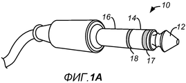
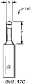
[0003] Стандартные соединители для аудио или штекеры доступны в трех размерах согласно наружному диаметру штекера: штекер на 6,35 мм (1/4"), миниатюрный штекер на 3,5 мм (1/8") и субминиатюрный штекер на 2,5 мм (3/32"). Штекеры включают в себя многочисленные проводящие области, которые протягиваются по длине соединителей в различных частях штекера, таких как концевая часть, гильза и одна или более средних частей между концевой частью и гильзой, что приводит к тому, что соединители зачастую упоминаются как TRS (концевая часть, кольцо и гильза) соединители.[0003] Standard audio connectors or plugs are available in three sizes according to the outer diameter of the plug: 6.35 mm (1/4 ") plug, 3.5 mm (1/8") miniature plug, and 2 subminiature plug, 5 mm (3/32 "). The plugs include numerous conductive regions that extend along the length of the connectors in different parts of the plug, such as an end portion, a sleeve, and one or more middle parts between the end portion and the sleeve, resulting in that connectors are often referred to as TRS (end piece, ring and sleeve) connectors.
[0004] Фиг. 1A и 1B иллюстрируют примеры штекеров 10 и 20 для аудио, имеющих три и четыре проводящих части, соответственно. Как показано на Фиг. 1A, штекер 10 включает в себя проводящую концевую часть 12, проводящую гильзу 16 и проводящее кольцо 14, электрически изолированное от концевой части 12 и гильзы 16 посредством изоляционных колец 17 и 18. Три проводящих части 12, 14, 16 предназначаются для левого и правого аудио и заземляющего соединения. Штекер 20, показанный на Фиг. 1B, включает в себя четыре проводящих части: проводящую концевую часть 22, проводящую гильзу 26 и два проводящих кольца 24, 25 и тем самым иногда упоминается как соединитель TRRS (концевая часть, кольцо, кольцо, гильза). Четыре проводящих части электрически изолируются посредством изоляционных колец 27, 28 и 29 и типично используются для левого и правого аудиосигналов, сигналов микрофона и заземляющих сигналов. Как видно из Фиг. 1A и 1B, каждый из штекеров 10 и 20 для аудио является независимым от ориентации. Иными словами, проводящие части полностью окружают соединитель, формирующий 360-градусные контакты, так что для штекерной части соединителей отсутствует различие верх, низ или бок.[0004] FIG. 1A and 1B illustrate examples of
[0005] Когда штекеры 10 и 20 являются 3,5-миллиметровыми миниатюрными соединителями, внешний диаметр проводящей гильзы 16, 26 и проводящих колец 14, 24, 25 составляет 3,5 мм, а длина вставки соединителя составляет 14 мм. Для 2,5-миллиметровых субминиатюрных соединителей внешний диаметр проводящей гильзы составляет 2,5 мм, а длина вставки соединителя составляет 11 мм. Такие TRS- и TRRS-соединители используются во многих предлагаемых на рынке MP3-проигрывателях и смартфонах, а также в других электронных устройствах. Электронные устройства, к примеру, MP3-проигрыватели и смартфоны постоянно проектируются с возможностью утончения и уменьшения и/или включения в себя устройство отображения видеоданных с экранами, которые подступают максимально возможно близко к внешнему краю устройств. Диаметр и длина современных соединителей для аудио на 3,5 мм и даже 2,5 мм являются ограничивающими факторами для уменьшения и утончения таких устройств и для предоставления возможности увеличения устройств отображения для данного форм-фактора.[0005] When the
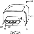
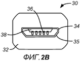
[0006] Многие стандартные соединители для данных также доступны только с размерами, которые являются ограничивающими факторами в создании портативных электронных устройств более компактными. Дополнительно и в отличие от соединителей TRS, поясненных выше по тексту, многие стандартные соединители для данных требуют сопряжения с соответствующим соединителем в одной конкретной ориентации. Такие соединители могут упоминаться как поляризованные соединители. В качестве примера поляризованного соединителя, Фиг. 2A и 2B иллюстрируют микро-USB-соединитель 30, наименьший из доступных на сегодня USB-соединителей. Соединитель 30 включает в себя корпус 32 и металлическую оболочку 34, которая протягивается из корпуса 32 и может быть вставлена в соответствующий розеточный соединитель. Как показано на Фиг. 2A, 2B, оболочка 34 имеет изогнутые углы 35, сформированные на одной из нижних пластин. Аналогично, розеточный соединитель (не показан), с которым сопрягается соединитель 30, имеет отверстие вставки с согласующими изогнутыми элементами, которые не допускают вставку оболочки 34 в розеточный соединитель неправильным способом. Иными словами, она может быть вставлена только одним способом, т.е. в ориентации, в которой изогнутые части оболочки 34 совмещаются с согласующими изогнутыми частями в розеточном соединителе. Иногда пользователю трудно определять, когда поляризованный соединитель, к примеру, соединитель 30, ориентирован в корректной позиции вставки.[0006] Many standard data connectors are also only available with dimensions that are limiting factors in making portable electronic devices more compact. Additionally and unlike the TRS connectors explained above, many standard data connectors require pairing with the corresponding connector in one specific orientation. Such connectors may be referred to as polarized connectors. As an example of a polarized connector, FIG. 2A and 2B illustrate the
[0007] Соединитель 30 также включает в себя внутреннюю полость 38 в оболочке 34 вместе с контактами 36, сформированными в полости. Полость 38 подвержена скоплению и улавливанию мусора в полости, что иногда может создавать помехи для сигнальных соединений с контактами 36. Также и в дополнение к проблеме ориентации, даже когда соединитель 30 совмещен надлежащим образом, вставка и извлечение соединителя не являются точными, и может возникать ощущение несоответствия. Дополнительно, даже когда соединитель полностью вставлен, он может иметь нежелательную степень пошатывания, что может приводить либо к неисправному соединению, либо к повреждению.[0007] The
[0008] Многие другие общераспространенные соединители для данных, включающие в себя стандартные USB-соединители, мини-USB-соединители, FireWire-соединители, а также многие фирменные соединители, используемые в стандартном портативном мультимедийном электронном оборудовании, испытывают некоторые или все эти недостатки либо аналогичные недостатки.[0008] Many other common data connectors, including standard USB connectors, mini USB connectors, FireWire connectors, as well as many proprietary connectors used in standard portable multimedia electronic equipment, experience some or all of these shortcomings or similar limitations.
СУЩНОСТЬ ИЗОБРЕТЕНИЯSUMMARY OF THE INVENTION
[0009] Различные варианты осуществления изобретения относятся к штекерным соединителям и розеточным соединителям, которые преодолевают некоторые или все вышеописанные недостатки. Другие варианты осуществления изобретения относятся к способам изготовления таких штекерных и/или розеточных соединителей, а также электронных устройств, которые включают в себя такие соединители. Варианты осуществления изобретения не ограничены конкретными типами соединителя и могут использоваться для множества вариантов применения. Тем не менее, некоторые варианты осуществления оптимально подходят для использования в качестве соединителей для аудио, а некоторые варианты осуществления оптимально подходят для соединителей для данных.[0009] Various embodiments of the invention relate to plug connectors and female connectors that overcome some or all of the disadvantages described above. Other embodiments of the invention relate to methods for manufacturing such plug and / or socket connectors, as well as electronic devices that include such connectors. Embodiments of the invention are not limited to specific types of connector and can be used for a variety of applications. However, some embodiments are optimally suitable for use as connectors for audio, and some embodiments are optimally suitable for connectors for data.
[0010] С учетом недостатков в доступных на сегодня соединителях для аудио и соединителях для данных, как описано выше по тексту, некоторые варианты осуществления настоящего изобретения относятся к улучшенным штекерным соединителям для аудио и/или соединителям для данных, которые имеют уменьшенную длину и толщину штекера, интуитивную ориентацию вставки и плавное целостное ощущение при вставке и извлечении из соответствующего розеточного соединителя. Дополнительно, некоторые варианты осуществления штекерных соединителей согласно настоящему изобретению имеют внешние контакты вместо внутренних контактов и не включают в себя полость, которая подвержена скоплению и улавливанию мусора.[0010] In view of the disadvantages of the audio connectors and data connectors available today, as described above, some embodiments of the present invention relate to improved plug connectors for audio and / or data connectors that have a reduced plug length and thickness. , intuitive orientation of the insert and a smooth, holistic feel when inserting and removing from the corresponding receptacle connector. Additionally, some embodiments of the plug connectors according to the present invention have external contacts instead of internal contacts and do not include a cavity that is susceptible to accumulation and collection of debris.
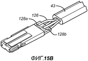
[0011] Один конкретный вариант осуществления изобретения относится к штекерному соединителю с двойной ориентацией, имеющему внешние контакты, носимые (лепестковым) выводом соединителя. Этот вывод соединителя может включать в себя первую и вторую противоположные стороны с первым набором контактов, сформированным на первой стороне, и вторым набором контактов, сформированным на второй стороне. Первый набор контактов может быть симметрично разнесен со вторым набором контактов, и вывод соединителя может иметь 180-градусную симметричную форму, так что он может быть вставлен и функционально соединен с соответствующим розеточным соединителем в любой из двух ориентаций вставки. В некоторых вариантах осуществления штекерный соединитель дополнительно включает в себя один или более заземляющих контактов, сформированных на боковых поверхностях вывода соединителя, которые протягиваются между первой и второй поверхностями, и в некоторых дополнительных вариантах осуществления вывод соединителя включает в себя наконечник или заземляющее кольцо, которое закрывает концевую часть соединителя и протягивается от концевой части к корпусу вдоль, по меньшей мере, части каждой из боковых поверхностей. В некоторых дополнительных вариантах осуществления вывод соединителя включает в себя, по меньшей мере, одно средство фиксации, адаптированное для зацепления со средством фиксации на соответствующем розеточном соединителе.[0011] One particular embodiment of the invention relates to a dual orientation plug connector having external contacts carried by the (tab) terminal of the connector. This connector terminal may include first and second opposite sides with a first set of contacts formed on the first side and a second set of contacts formed on the second side. The first set of contacts may be symmetrically spaced with the second set of contacts, and the terminal of the connector may have a 180 degree symmetrical shape so that it can be inserted and functionally connected to the corresponding receptacle connector in either of the two insert orientations. In some embodiments, the plug connector further includes one or more grounding contacts formed on side surfaces of the connector output that extend between the first and second surfaces, and in some further embodiments, the connector output includes a ferrule or ground ring that closes the end part of the connector and extends from the end part to the housing along at least part of each of the side surfaces. In some additional embodiments, the connector outlet includes at least one locking means adapted to engage with the locking means on a corresponding receptacle connector.
[0012] В другом варианте осуществления изобретение относится к электрическому соединителю с двойной ориентацией, содержащему корпус и (лепестковый) вывод соединителя, протягивающийся продольно от корпуса, который включает в себя первую и вторую противоположные поверхности. Множество электрических контактов переносятся выводом соединителя, включающим в себя первый набор внешних контактов, сформированный на первой поверхности, и второй набор внешних контактов, сформированный на второй поверхности. Вывод соединителя имеет форму со 180-градусной симметрией, и первый набор контактов симметрично разнесен со вторым набором контактов, обеспечивая возможность вставки соединителя в соответствующий розеточный соединитель в любой из двух ориентаций. В некоторых случаях вывод соединителя дополнительно может включать в себя боковую периферийную поверхность, которая протягивается между первой и второй противоположными поверхностями, и, по меньшей мере, один заземляющий контакт, сформированный на боковой периферийной поверхности. Дополнительно, в некоторых вариантах осуществления соединитель дополнительно включает в себя металлическое заземляющее кольцо, которое, в общем, задает форму вывода соединителя и включает в себя отверстия на обеих первой и второй поверхностях, на которых первый и второй наборы контактов, соответственно, сформированы и окружены диэлектриком. Еще в некоторых других вариантах осуществления корпус включает в себя гибкий элемент или изготавливается из гибкого материала, который позволяет соединителю изгибаться относительно оси вставки, в которой соединитель сопрягается с розеточным соединителем.[0012] In another embodiment, the invention relates to a dual orientation electrical connector comprising a housing and a (tab) terminal of a connector extending longitudinally from the housing, which includes first and second opposed surfaces. A plurality of electrical contacts are carried by a connector terminal including a first set of external contacts formed on a first surface and a second set of external contacts formed on a second surface. The connector pin has a 180 degree symmetry shape, and the first set of contacts is symmetrically spaced with the second set of contacts, allowing the connector to be inserted into the corresponding receptacle connector in either of two orientations. In some cases, the terminal of the connector may further include a lateral peripheral surface that extends between the first and second opposite surfaces, and at least one ground contact formed on the lateral peripheral surface. Additionally, in some embodiments, the connector further includes a metal ground ring, which generally defines the shape of the terminal of the connector and includes holes on both first and second surfaces on which the first and second sets of contacts are respectively formed and surrounded by a dielectric . In still some other embodiments, the housing includes a flexible member or is made of a flexible material that allows the connector to bend relative to the axis of the insert, in which the connector mates with a female connector.
[0013] В еще одном другом варианте осуществления изобретение относится к электрическому штекерному соединителю с двойной ориентацией, имеющему корпус, кабель, прикрепленный к корпусу, и неполяризованный (лепестковый) вывод соединителя, протягивающийся продольно от корпуса. Вывод соединителя может иметь, в общем, прямоугольное поперечное сечение, заданное первой и второй главными противоположными поверхностями и первой и второй противоположными боковыми поверхностями, протягивающимися между первой и второй главными поверхностями. Множество электрических скользящих контактов может переноситься выводом соединителя, включающим в себя первый набор внешних контактов, сформированных на первой главной поверхности и протягивающихся параллельно друг другу по длине соединителя, и второй набор внешних контактов, сформированных на второй главной поверхности и протягивающихся параллельно друг другу по длине соединителя. Соединитель также может включать в себя первое и второе средства фиксации, сформированные на первой и второй противоположных боковых поверхностях, соответственно, которые адаптированы для зацепления со средствами фиксации на соответствующем розеточном соединителе, чтобы скреплять соединители вместе во время события сопряжения. В некоторых вариантах осуществления первое средство фиксации также может функционировать в качестве первого заземляющего контакта, а второе средство фиксации также может функционировать в качестве второго заземляющего контакта. Первый набор контактов может быть симметрично разнесен со вторым набором контактов, и первый заземляющий контакт может быть симметрично разнесен со вторым заземляющим контактом, так что вывод соединителя имеет 180-градусную симметрию и может быть вставлен и функционально соединен с соответствующим розеточным соединителем в любой из двух позиций.[0013] In yet another embodiment, the invention relates to a dual orientation electrical plug connector having a housing, a cable attached to the housing, and a non-polarized (tab) terminal of the connector extending longitudinally from the housing. The connector terminal may have a generally rectangular cross-section defined by the first and second major opposite surfaces and the first and second opposite side surfaces extending between the first and second major surfaces. A plurality of electrical sliding contacts may be carried by a connector terminal including a first set of external contacts formed on the first main surface and extending parallel to each other along the length of the connector, and a second set of external contacts formed on the second main surface and extending parallel to each other along the length of the connector . The connector may also include first and second locking means formed on the first and second opposite side surfaces, respectively, which are adapted to engage with the locking means on the corresponding receptacle connector to hold the connectors together during the mating event. In some embodiments, the first fixing means may also function as a first grounding contact, and the second fixing means may also function as a second grounding contact. The first set of contacts can be symmetrically spaced with the second set of contacts, and the first ground contact can be symmetrically spaced with the second ground contact, so that the terminal of the connector has 180 degree symmetry and can be inserted and functionally connected to the corresponding receptacle connector in any of two positions .
[0014] Другие варианты осуществления изобретения относятся к электрическим розеточным соединителям. В одном варианте осуществления розеточный соединитель может включать в себя кожух, который задает внутреннюю полость, протягивающуюся в направлении глубины кожуха, и множество электрических контактов, размещенных в полости. Полость может иметь 180-градусную симметричную форму, так что соответствующий штекерный соединитель может быть вставлен в полость в любой из двух ориентаций вставки. Дополнительно, множество контактов может включать в себя первый набор контактов, размещенный на первой внутренней поверхности полости, и второй набор контактов, размещенный на второй внутренней поверхности полости, разнесенной от первой внутренней поверхности в противоположной взаимосвязи. Первый и второй наборы контактов дополнительно могут быть зеркальными отражениями друг друга. В некоторых вариантах осуществления, розеточный соединитель также может включать в себя по меньшей мере одно средство фиксации, адаптированное для зацепления со средством фиксации на соответствующем штекерном соединителе. В еще других вариантах осуществления, розеточный соединитель может включать в себя первое и второе средства фиксации, размещенные на противоположных боковых поверхностях полости, адаптированные для зацепления с первым и вторым средствами фиксации на соответствующем штекерном соединителе.[0014] Other embodiments of the invention relate to electrical outlet connectors. In one embodiment, the receptacle connector may include a housing that defines an internal cavity extending toward the depth of the housing and a plurality of electrical contacts disposed in the cavity. The cavity may have a 180-degree symmetrical shape, so that the corresponding plug connector can be inserted into the cavity in either of the two insert orientations. Additionally, the plurality of contacts may include a first set of contacts located on the first inner surface of the cavity, and a second set of contacts located on the second inner surface of the cavity spaced from the first inner surface in an opposite relationship. The first and second sets of contacts can additionally be mirror images of each other. In some embodiments, the receptacle connector may also include at least one locking means adapted to engage with the locking means on the corresponding plug connector. In still other embodiments, the receptacle connector may include first and second fixation means arranged on opposite side surfaces of the cavity, adapted to engage with the first and second fixation means on a corresponding plug connector.
[0015] В другом варианте осуществления изобретение относится к электрическому штекерному соединителю, который включает в себя проводящий наконечник или заземляющее кольцо, чтобы изолировать контакты соединителя от помех. Соединитель дополнительно может включать в себя корпус и вывод соединителя, который прикреплен и протягивается продольно от корпуса. Проводящий наконечник может закрывать концевую часть соединителя и протягиваться от концевой части к корпусу вдоль, по меньшей мере, части боковых поверхностей вывода соединителя. Множество внешних контактов может переноситься выводом соединителя в местоположении, по меньшей мере, частично окруженном посредством проводящего наконечника. В некоторых вариантах осуществления, множество внешних контактов может включать в себя контакты, сформированные на первой и второй главных противоположных поверхностях вывода соединителя, и в некоторых вариантах осуществления, контакты, сформированные на первой и второй поверхностях, скомпонованы на каждой поверхности в согласующих конфигурациях. Дополнительно, в некоторых вариантах осуществления проводящий наконечник может быть металлическим наконечником, и в некоторых вариантах осуществления соединитель дополнительно включает в себя первый и второй заземляющие контакты, сформированные на сторонах проводящего наконечника. В различных вариантах осуществления проводящий наконечник может быть U-образной рамкой или может, в общем, задавать форму вывода соединителя за исключением одной или более контактных областей вывода соединителя, где сформированы множество контактов.[0015] In another embodiment, the invention relates to an electrical plug connector that includes a conductive tip or a ground ring to isolate the connector pins from interference. The connector may further include a housing and a connector terminal that is attached and extends longitudinally from the housing. The conductive tip may close the end portion of the connector and extend from the end portion to the housing along at least a portion of the side surfaces of the terminal of the connector. A plurality of external contacts may be carried by the connector terminal at a location at least partially surrounded by a conductive tip. In some embodiments, the plurality of external contacts may include contacts formed on the first and second major opposite surfaces of the connector output, and in some embodiments, the contacts formed on the first and second surfaces are arranged on each surface in matching configurations. Additionally, in some embodiments, the conductive tip may be a metal tip, and in some embodiments, the connector further includes first and second ground contacts formed on the sides of the conductive tip. In various embodiments, the conductive tip may be a U-shaped frame, or may generally define the shape of the connector output with the exception of one or more contact areas of the connector output where a plurality of contacts are formed.
[0016] В еще одном другом варианте осуществления, раскрывается способ изготовления штекерного соединителя, имеющего корпус и вывод, который адаптирован для вставки в соответствующий розеточный соединитель. Способ включает в себя: формирование (лепесткового) вывода соединителя, чтобы он имел первую и вторую главные противоположные поверхности, третью и четвертую противоположные боковые поверхности, протягивающиеся между первой и второй поверхностями, и 180-градусную симметричную конструкцию, так что плоскость, делящая пополам ширину вывода соединителя под углом, перпендикулярным первой и второй главным поверхностям, разделяет вывод на левую и правую части, которые имеют по существу идентичную внешнюю форму, а горизонтальная плоскость, делящая пополам высоту вывода соединителя под углом, перпендикулярным третьей и четвертой боковым поверхностям, разделяет вывод на верхнюю и нижнюю части, которые имеют по существу идентичную внешнюю форму; формирование первой контактной области на первой главной поверхности вывода соединителя и второй контактной области на второй главной поверхности вывода соединителя напротив первой главной поверхности, причем первая и вторая контактные области имеют по существу идентичный размер и форму и включают в себя равное число контактов, при этом контакты в первой контактной области скомпонованы в первой конфигурации согласно первому разнесению, и контакты во втором контакте также скомпонованы в первой конфигурации согласно первому разнесению; и прикрепление кабеля, имеющего множество изолированных проводов, к корпусу, так что каждый отдельный провод во множестве изолированных проводов электрически подсоединен к контакту в любой из первой или второй контактных областей.[0016] In yet another embodiment, a method for manufacturing a plug connector having a housing and a terminal that is adapted for insertion into an appropriate receptacle connector is disclosed. The method includes: forming a (petal) terminal of the connector so that it has the first and second main opposite surfaces, the third and fourth opposite side surfaces extending between the first and second surfaces, and a 180-degree symmetrical structure, so that the plane bisecting the width the outlet of the connector at an angle perpendicular to the first and second major surfaces, divides the outlet into left and right parts, which have a substantially identical external shape, and the horizontal plane dividing bisecting the height of the connector outlet at an angle perpendicular to the third and fourth side surfaces, separates the outlet into upper and lower parts that have a substantially identical external shape; the formation of the first contact area on the first main surface of the output of the connector and the second contact area on the second main surface of the output of the connector opposite the first main surface, the first and second contact areas are essentially identical in size and shape and include an equal number of contacts, while the contacts in the first contact area are arranged in the first configuration according to the first spacing, and the contacts in the second contact are also arranged in the first configuration according to the first spacing th; and attaching a cable having a plurality of insulated wires to the housing, such that each individual wire in a plurality of insulated wires is electrically connected to a contact in any of the first or second contact areas.
[0017] Чтобы лучше понимать характер и преимущества настоящего изобретения, следует обратиться к нижеприведенному описанию и прилагаемым чертежам. Тем не менее, следует понимать, что каждая из фигур предоставляется только в целях иллюстрации и не предназначена для задания пределов объема настоящего изобретения. Кроме того, в качестве общего правила, и если из описания не очевидно обратное, когда элементы на различных фигурах используют идентичные ссылочные позиции, элементы являются, в общем, либо идентичными, либо, по меньшей мере, аналогичными по функции или назначению.[0017] In order to better understand the nature and advantages of the present invention, reference should be made to the description below and the accompanying drawings. However, it should be understood that each of the figures is provided for purposes of illustration only and is not intended to set the scope of the present invention. In addition, as a general rule, and if the opposite is not obvious from the description, when the elements in the various figures use the same reference position, the elements are, in general, either identical, or at least similar in function or purpose.
КРАТКОЕ ОПИСАНИЕ ЧЕРТЕЖЕЙBRIEF DESCRIPTION OF THE DRAWINGS
[0018] Фиг. 1A и 1B показывают виды в перспективе ранее известных штекерных TRS-соединителей для аудио;[0018] FIG. 1A and 1B show perspective views of previously known TRS plug connectors for audio;
[0019] Фиг. 2A показывает вид в перспективе ранее известного штекерного микро-USB-соединителя, тогда как Фиг. 2B показывает вид в плане спереди микро-USB-соединителя, показанного на Фиг. 2A;[0019] FIG. 2A shows a perspective view of a previously known plug-in micro USB connector, while FIG. 2B shows a front plan view of the micro USB connector shown in FIG. 2A;
[0020] Фиг. 3A является упрощенным видом сверху штекерного соединителя 40 согласно одному варианту осуществления настоящего изобретения;[0020] FIG. 3A is a simplified top view of a
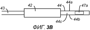
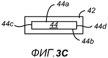
[0021] Фиг. 3B и 3C являются упрощенными видами сбоку и спереди, соответственно, соединителя 40, показанного на Фиг. 3A;[0021] FIG. 3B and 3C are simplified side and front views, respectively, of the
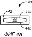
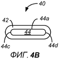
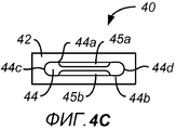
[0022] Фиг. 4A-4C являются видом спереди альтернативных вариантов осуществления соединителя 40 согласно настоящему изобретению;[0022] FIG. 4A-4C are a front view of alternative embodiments of a
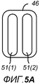
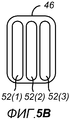
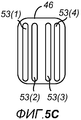
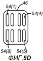
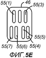
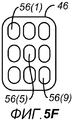
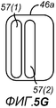
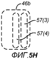
[0023] Фиг. 5A-5H являются упрощенными видами сверху схем размещения контактов в контактной области 46 соединителя 40 согласно различным вариантам осуществления изобретения;[0023] FIG. 5A-5H are simplified plan views of contact patterns in the
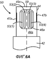
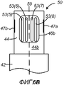
[0024] Фиг. 6A является упрощенным видом контактной области 46a штекерного соединителя 50, и Фиг. 6B является упрощенным видом контактной области 46a штекерного соединителя 50, показанного на Фиг. 3A и 3B согласно конкретному варианту осуществления настоящего изобретения;[0024] FIG. 6A is a simplified view of the
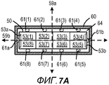
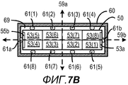
[0025] Фиг. 7A и 7B являются схемами, иллюстрирующими набор примерных местоположений контактов согласно некоторым вариантам осуществления настоящего изобретения;[0025] FIG. 7A and 7B are diagrams illustrating a set of exemplary contact locations according to some embodiments of the present invention;
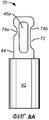
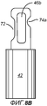
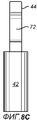
[0026] Фиг. 8A-8C являются упрощенными видами в плане сверху, снизу и сбоку штекерного контактного соединителя, который включает в себя ключ ориентации согласно другому варианту осуществления настоящего изобретения;[0026] FIG. 8A-8C are simplified plan views from above, below, and side of a plug connector that includes an orientation key according to another embodiment of the present invention;
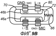
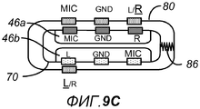
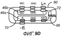
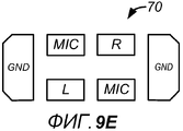
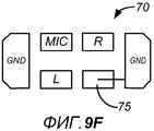
[0027] Фиг. 9A-9F являются упрощенными схематичными представлениями компоновок контактов соединителей согласно дополнительным вариантам осуществления изобретения;[0027] FIG. 9A-9F are simplified schematic diagrams of connector pinouts according to further embodiments of the invention;
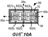
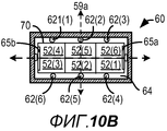
[0028] Фиг. 10A и 10B являются схемами, иллюстрирующими набор примерных местоположений контактов согласно некоторым другим вариантам осуществления настоящего изобретения;[0028] FIG. 10A and 10B are diagrams illustrating a set of exemplary contact locations according to some other embodiments of the present invention;
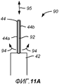
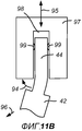
[0029] Фиг. 11A является упрощенным видом сбоку в поперечном сечении штекерного соединителя 90 согласно одному варианту осуществления настоящего изобретения;[0029] FIG. 11A is a simplified cross-sectional side view of
[0030] Фиг. 11B является упрощенным видом сбоку штекерного соединителя 90, показанного на Фиг. 11A, который иллюстрирует, как соединитель может изгибаться при извлечении из розеточного соединителя посредством вытягивания в направлении, которое пересекает ось вставки соединителя;[0030] FIG. 11B is a simplified side view of the
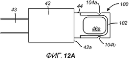
[0031] Фиг. 12A является упрощенным видом сверху штекерного соединителя 100 согласно другому варианту осуществления настоящего изобретения;[0031] FIG. 12A is a simplified top view of a
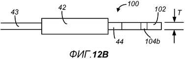
[0032] Фиг. 12B является упрощенным видом сбоку соединителя 100, показанного на Фиг. 12A;[0032] FIG. 12B is a simplified side view of the
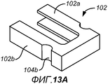
[0033] Фиг. 13A и 13B являются упрощенными видами в перспективе заземляющего кольца, которое может быть включено в состав некоторых вариантов осуществления настоящего изобретения;[0033] FIG. 13A and 13B are simplified perspective views of a grounding ring that may be included in some embodiments of the present invention;
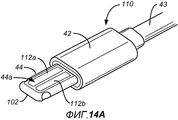
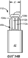
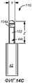
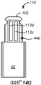
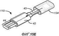
[0034] Фиг. 14A является упрощенным видом в перспективе штекерного соединителя 110 для аудио согласно одному варианту осуществления настоящего изобретения;[0034] FIG. 14A is a simplified perspective view of an
[0035] Фиг. 14B-14D являются упрощенными видами в плане штекерного соединителя для аудио, показанного на Фиг. 14A;[0035] FIG. 14B-14D are simplified plan views of a plug connector for the audio shown in FIG. 14A;
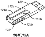
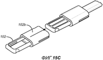
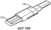
[0036] Фиг. 15A-15E являются покомпонентными видами в перспективе соединителя 110, показанного на Фиг. 14A, на различных стадиях изготовления;[0036] FIG. 15A-15E are exploded perspective views of a
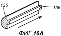
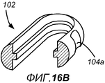
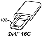
[0037] Фиг. 16A-16C иллюстрируют один пример того, как может формироваться заземляющее кольцо 102, показанное на Фиг. 14A;[0037] FIG. 16A-16C illustrate one example of how the
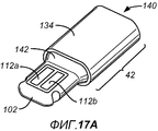
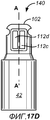
[0038] Фиг. 17A является упрощенным видом в перспективе штекерного соединителя 140 для аудио согласно другому варианту осуществления настоящего изобретения;[0038] FIG. 17A is a simplified perspective view of an
[0039] Фиг. 17B-17D являются упрощенными видами в плане соединителя 140, показанного на Фиг. 17A;[0039] FIG. 17B-17D are simplified plan views of a
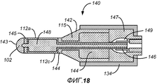
[0040] Фиг. 18 является упрощенным видом в поперечном сечении соединителя 140 вдоль линий A-A', показанного на Фиг. 17D;[0040] FIG. 18 is a simplified cross-sectional view of a
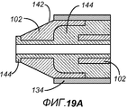
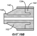
[0041] Фиг. 19A и 19B являются упрощенными видами в поперечном сечении альтернативного способа подсоединения изолятора 144 к заземляющему кольцу 115, показанного на Фиг. 18;[0041] FIG. 19A and 19B are simplified cross-sectional views of an alternative method of connecting the
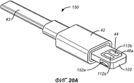
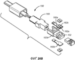
[0042] Фиг. 20A является упрощенным видом в перспективе штекерного соединителя 150 согласно одному варианту осуществления настоящего изобретения;[0042] FIG. 20A is a simplified perspective view of a
[0043] Фиг. 20B является покомпонентным видом штекерного соединителя 150, показанного на Фиг. 20A;[0043] FIG. 20B is an exploded view of the
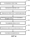
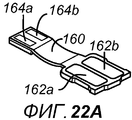
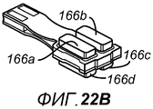
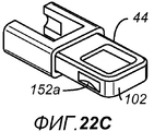
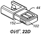
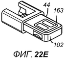
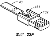
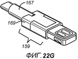
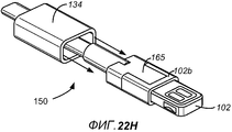
[0044] Фиг. 21 является блок-схемой последовательности операций способа, иллюстрирующей этапы, ассоциированные с изготовлением соединителя 150 согласно одному варианту осуществления изобретения;[0044] FIG. 21 is a flowchart illustrating steps associated with manufacturing a
[0045] Фиг. 22A-22H являются упрощенными видами в перспективе соединителя 150, показанного на Фиг. 20A и 18B, на различных стадиях изготовления, поясненных относительно Фиг. 21;[0045] FIG. 22A-22H are simplified perspective views of a
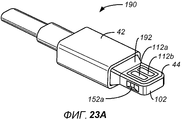
[0046] Фиг. 23A является упрощенным видом в перспективе штекерного соединителя 190 согласно другому варианту осуществления изобретения;[0046] FIG. 23A is a simplified perspective view of a
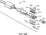
[0047] Фиг. 23B является покомпонентным видом штекера 190 соединителя, показанного на Фиг. 23A;[0047] FIG. 23B is an exploded view of a
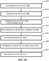
[0048] Фиг. 24 является блок-схемой последовательности операций способа, иллюстрирующей этапы, ассоциированные с изготовлением соединителя 190 согласно одному варианту осуществления изобретения;[0048] FIG. 24 is a flowchart illustrating steps associated with manufacturing a
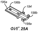
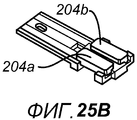
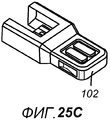
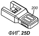
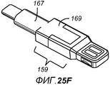
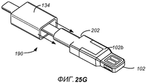
[0049] Фиг. 25A-25G являются упрощенными видами в перспективе соединителя 190, показанного на Фиг. 23A и 21B, на различных стадиях изготовления, поясненных относительно Фиг. 24;[0049] FIG. 25A-25G are simplified perspective views of a
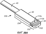
[0050] Фиг. 26A является упрощенным видом в перспективе гибкого штекерного соединителя 230 согласно другому варианту осуществления изобретения;[0050] FIG. 26A is a simplified perspective view of a
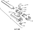
[0051] Фиг. 26B является покомпонентным видом штекерного соединителя 230;[0051] FIG. 26B is an exploded view of
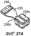
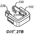
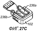
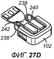
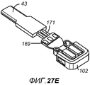
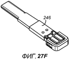
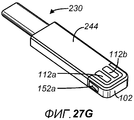
[0052] Фиг. 27A-27G являются упрощенными видами в перспективе соединителя 230, показанного на Фиг. 26A и 24B, на различных стадиях изготовления;[0052] FIG. 27A-27G are simplified perspective views of a
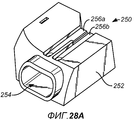
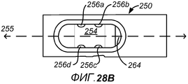
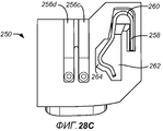
[0053] Фиг. 28A является упрощенным видом в перспективе гнезда 250 розеточного соединителя согласно одному варианту осуществления изобретения;[0053] FIG. 28A is a simplified perspective view of a
[0054] Фиг. 28B и 28C являются видами в плане спереди и снизу гнезда 250 соединителя, показанного на Фиг. 28A;[0054] FIG. 28B and 28C are front and bottom views of the
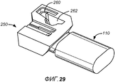
[0055] Фиг. 29 является упрощенным видом в перспективе, показывающим штекерный соединитель 110, вставленный в гнездо 250 соединителя;[0055] FIG. 29 is a simplified perspective view showing a
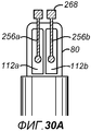
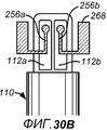
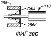
[0056] Фиг. 30A-30C иллюстрируют различные позиции, в которых может быть размещена верхняя часть контактов, ассоциированная с розеточным соединителем согласно настоящему изобретению;[0056] FIG. 30A-30C illustrate various positions in which the top of the contacts associated with the receptacle connector of the present invention can be placed;
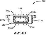
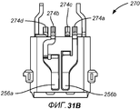
[0057] Фиг. 31A и 31B являются видами в плане спереди и снизу гнезда 200 розеточного соединителя согласно одному варианту осуществления изобретения;[0057] FIG. 31A and 31B are front and bottom views of a
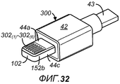
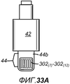
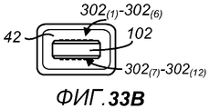
[0058] Фиг. 32 является упрощенным видом в перспективе штекерного соединителя 300 согласно одному варианту осуществления настоящего изобретения;[0058] FIG. 32 is a simplified perspective view of a
[0059] Фиг. 33A-33C являются упрощенными видами в плане штекерного соединителя 300, показанного на Фиг. 32;[0059] FIG. 33A-33C are simplified plan views of
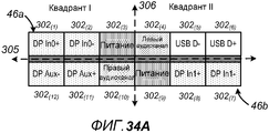
[0060] Фиг. 34A и 34B являются схемами, иллюстрирующими местоположения штырьковых выводов соединителя 300 в двух различных ориентациях согласно варианту осуществления изобретения;[0060] FIG. 34A and 34B are diagrams illustrating pin locations of
[0061] Фиг. 35 является упрощенным покомпонентным видом в перспективе штекерного соединителя 310 согласно другому варианту осуществления изобретения;[0061] FIG. 35 is a simplified exploded perspective view of a
[0062] Фиг. 36A и 36B являются упрощенными видами в плане сверху и сбоку печатной платы 312a, показанной на Фиг. 35 согласно одному варианту осуществления настоящего изобретения;[0062] FIG. 36A and 36B are simplified top and side plan views of the printed
[0063] Фиг. 37 является блок-схемой последовательности операций способа, иллюстрирующей этапы, ассоциированные с изготовлением соединителя 310 согласно одному варианту осуществления изобретения;[0063] FIG. 37 is a flowchart illustrating steps associated with manufacturing a
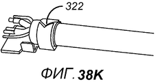
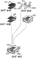
[0064] Фиг. 38A-38P иллюстрируют различные виды штекерного соединителя 310 на различных стадиях изготовления, поясненных относительно Фиг. 37;[0064] FIG. 38A-38P illustrate various views of
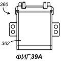
[0065] Фиг. 39A-39D иллюстрируют различные упрощенные виды гнезда 360 розеточного соединителя согласно одному варианту осуществления изобретения;[0065] FIG. 39A-39D illustrate various simplified views of a
[0066] Фиг. 40A-40D иллюстрируют различные упрощенные виды гнезда 370 розеточного соединителя согласно другому варианту осуществления изобретения;[0066] FIG. 40A-40D illustrate various simplified views of a
[0067] Фиг. 41A-41G иллюстрируют различные виды розеточного соединителя 360 на различных стадиях изготовления;[0067] FIG. 41A-41G illustrate various types of
[0068] Фиг. 42 является упрощенным видом в перспективе штекера 390 соединителя согласно другому варианту осуществления изобретения.[0068] FIG. 42 is a simplified perspective view of a
[0069] Фиг. 43 является упрощенным видом в перспективе штекера 400 соединителя согласно другому варианту осуществления изобретения;[0069] FIG. 43 is a simplified perspective view of a
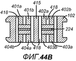
[0070] Фиг. 44A является упрощенным видом в перспективе в частичном сечении штекерного соединителя 400, а Фиг. 44B является упрощенным видом в поперечном сечении штекерного соединителя 400;[0070] FIG. 44A is a simplified partial cross-sectional perspective view of
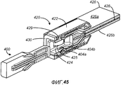
[0071] Фиг. 45 является упрощенным видом в перспективе в частичном сечении штекерного соединителя 400, вставленного в гнездо 420 розеточного соединителя;[0071] FIG. 45 is a simplified perspective view in partial cross-section of a
[0072] Фиг. 46A-46D иллюстрируют один пример соединителя 440, имеющего пять аналоговых контактов, а также волоконно-оптический кабель 445, который проходит через центр соединителя;[0072] FIG. 46A-46D illustrate one example of a
[0073] Фиг. 47 является упрощенным видом в перспективе штекерного соединителя 150 согласно другому варианту осуществления изобретения;[0073] FIG. 47 is a simplified perspective view of a
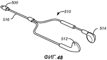
[0074] Фиг. 48 является упрощенным видом в перспективе гарнитуры 160, которая включает в себя соединитель 150, показанный на Фиг. 38 согласно варианту осуществления изобретения;[0074] FIG. 48 is a simplified perspective view of a
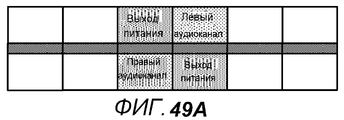
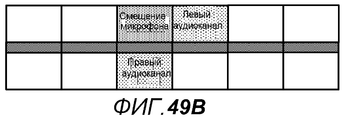
[0075] Фиг. 49A является схемой, иллюстрирующей местоположения штырьковых выводов соединителя 150, работающего в режиме шины Mickey согласно одному варианту осуществления изобретения, а Фиг. 49B является схемой, иллюстрирующей местоположения штырьковых выводов соединителя 150, работающего в унаследованном/обратно совместимом режиме согласно одному варианту осуществления изобретения;[0075] FIG. 49A is a diagram illustrating pin locations of a
[0076] Фиг. 50 является упрощенным видом в перспективе штекера 170 соединителя согласно другому варианту осуществления изобретения;[0076] FIG. 50 is a simplified perspective view of a
[0077] Фиг. 51 является упрощенным видом в перспективе кабеля 180 USB-адаптера, имеющего USB-соединитель на одном конце и соединитель 170, показанный на Фиг. 50, на другом конце согласно варианту осуществления изобретения;[0077] FIG. 51 is a simplified perspective view of a
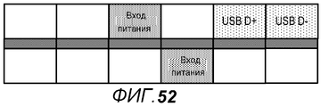
[0078] Фиг. 52 является схемой, иллюстрирующей местоположения штырьковых выводов штекера 170 соединителя, показанного на Фиг. 50 согласно одному варианту осуществления изобретения;[0078] FIG. 52 is a diagram illustrating the locations of the pin terminals of the
[0079] Фиг. 53 является упрощенным видом в перспективе штекера 190 соединителя согласно другому варианту осуществления изобретения;[0079] FIG. 53 is a simplified perspective view of a
[0080] Фиг. 54 является упрощенным видом в перспективе кабеля 200 аудио/видео адаптера, имеющего HDMI-соединители, USB-соединители и цифровые соединители для аудио на одном конце и соединитель 190 на другом конце согласно варианту осуществления изобретения;[0080] FIG. 54 is a simplified perspective view of an audio /
[0081] Фиг. 55 является упрощенным видом в перспективе кабеля 210 аудио/видео адаптера, имеющего соединители мини-порта отображения (mini DisplayPort) и USB на одном конце и (соединитель) аналогичный соединителю (520, показанному на Фиг. 50) 50 на другом конце согласно другому варианту осуществления изобретения;[0081] FIG. 55 is a simplified perspective view of an audio /
[0082] Фиг. 56 является упрощенным видом в перспективе кабеля 220 аудио/видео адаптера, имеющего соединитель минипорта отображения на одном конце и высокоскоростной соединитель на другом конце согласно другому варианту осуществления изобретения;[0082] FIG. 56 is a simplified perspective view of an audio /
[0083] Фиг. 57 является схемой, иллюстрирующей местоположения штырьковых выводов высокоскоростного соединителя 225, показанного на Фиг. 56 согласно одному варианту осуществления изобретения;[0083] FIG. 57 is a diagram illustrating pin locations of
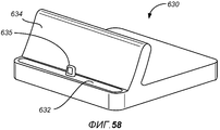
[0084] Фиг. 58 является упрощенным видом в перспективе установочной (док-) станции 230, которая включает в себя штекерный соединитель 235 согласно варианту осуществления изобретения;[0084] FIG. 58 is a simplified perspective view of a
[0085] Фиг. 59 является схемой, иллюстрирующей местоположения штырьковых выводов штекера 235 соединителя, показанного на Фиг. 52 согласно одному варианту осуществления изобретения;[0085] FIG. 59 is a diagram illustrating the locations of the pin terminals of the
[0086] Фиг. 60 является упрощенной иллюстративной блок-схемой подходящего электронного мультимедийного устройства, в котором могут содержаться или использоваться варианты осуществления изобретения; и[0086] FIG. 60 is a simplified illustrative block diagram of a suitable electronic multimedia device in which embodiments of the invention may be contained or used; and
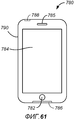
[0087] Фиг. 61 изображает иллюстративное представление одного конкретного варианта осуществления электронного мультимедийного устройства, подходящего для использования с вариантами осуществления настоящего изобретения.[0087] FIG. 61 is an illustrative view of one specific embodiment of an electronic multimedia device suitable for use with embodiments of the present invention.
ПОДРОБНОЕ ОПИСАНИЕ ИЗОБРЕТЕНИЯDETAILED DESCRIPTION OF THE INVENTION
[0088] Настоящее изобретение далее подробно описывается в отношении некоторых вариантов осуществления, как проиллюстрировано на прилагаемых чертежах. В последующем описании многие конкретные подробности пояснены для того, чтобы обеспечивать полное понимание настоящего изобретения. Тем не менее, для специалистов в данной области техники должно быть очевидным, что настоящее изобретение может осуществляться на практике без некоторых или всех этих конкретных подробностей. В других случаях известные подробности не описаны подробно, чтобы не затруднять излишне понимание настоящего изобретения.[0088] The present invention is further described in detail with respect to some embodiments, as illustrated in the accompanying drawings. In the following description, many specific details are set forth in order to provide a thorough understanding of the present invention. However, it should be apparent to those skilled in the art that the present invention may be practiced without some or all of these specific details. In other instances, well-known details are not described in detail so as not to obscure the understanding of the present invention.
[0089] Чтобы лучше принимать во внимание и понимать настоящее изобретение, сначала следует обратиться к Фиг. 3A-3C, которые являются упрощенными видами сверху, сбоку и спереди, соответственно, штекерного соединителя 40 согласно одному варианту осуществления настоящего изобретения. Соединитель 40 включает в себя корпус 42 и часть 44 (лепесткового) вывода. Кабель 43 прикреплен к корпусу 42, и часть 44 вывода протягивается от корпуса 42 в направлении, параллельном длине соединителя 40. Вывод 44 имеет такой размер, чтобы его можно было вставить в соответствующий розеточный соединитель во время события сопряжения, и включает в себя первую контактную область 46a, сформированную на первой главной поверхности 44a, и вторую контактную область 46b (не показана на Фиг. 3A-3C), сформированную на второй главной поверхности 44b напротив поверхности 44a. Множество контактов (не показаны на Фиг. 3A-3C) может формироваться в каждой из контактных областей 46a и 46b, так что когда вывод 44 вставляется в соответствующий розеточный соединитель, контакты в областях 46a, 46b электрически соединяются с соответствующими контактами в розеточном соединителе. В некоторых вариантах осуществления множество контактов являются самоочищающимися скользящими контактами, которые, после начального вхождения в контакт с контактом розеточного соединителя во время события сопряжения, скользят дальше мимо контакта розеточного соединителя со скользящим движением до достижения конечной желаемой контактной позиции.[0089] In order to better take into account and understand the present invention, first refer to FIG. 3A-3C, which are simplified top, side, and front views, respectively, of
[0090] Вывод 44 также включает в себя первую и вторую противоположные боковые поверхности 44c, 44d, которые протягиваются между первой и второй главными поверхностями 44a, 44b. Хотя вывод 44 показывается на Фиг. 3A-3C как имеющий по существу прямоугольную и по существу плоскую форму, в некоторых вариантах осуществления изобретения первая и вторая главные поверхности 44a, 44b могут иметь согласующие выгнутые или вогнутые изгибы или могут иметь согласующую область с выточкой, расположенную в центре между сторонами вывода 44. Контактные области 46a и 46b могут формироваться в областях с выточкой, и области с выточкой могут, например, протягиваться от дистальной концевой части вывода 44 полностью к основанию 42 или могут протягиваться вдоль только части длины вывода 44 (например, между 1/2-3/4 длины вывода), завершаясь в точке, не достигнув основания 42. Боковые поверхности 44c и 44d также могут иметь согласующие выгнутые или вогнутые изгибы.[0090] The terminal 44 also includes first and second opposing
[0091] В общем, форма и изгиб поверхностей 44a и 44b зеркально отражают друг друга, так же, как и форма и изгиб поверхностей 44a и 44b, в соответствии с конструкцией с двойной ориентацией соединителя 40, как описано ниже по тексту. Дополнительно, тогда как Фиг. 3A-3C показывают поверхности 44c, 44d как имеющие ширину, значительно меньшую ширины поверхностей 44a, 44b (например, меньшую или равную половине ширины поверхностей 44a, 44b), в некоторых вариантах осуществления изобретения боковые поверхности 44c, 44d имеют ширину, которая является относительно близкой либо даже равной или превышающей ширину поверхностей 44a, 44b.[0091] In general, the shape and bend of
[0092] Фиг. 4A-4C являются упрощенными видами в плане спереди вариантов осуществления соединителя 40, в которых корпус 42 и/или вывод 44 имеют различные формы поперечного сечения. Например, на Фиг. 4A главные поверхности 44a и 44b являются немного выгнутыми, тогда как на Фиг. 4B и 4C боковые поверхности 44c и 44d являются закругленными. Дополнительно, Фиг. 4C иллюстрирует пример соединителя, имеющего области 45a и 45b с выточкой, сформированные на главных поверхностях 44a и 44b, соответственно, вывода 44. Области с выточкой протягиваются от дистальной концевой части вывода 44 вдоль части длины вывода 44 и расположены в центре между боковыми поверхностями 44c и 44d. Специалисты в данной области техники должны понимать, что Фиг. 3C и 4A-4C являются только примерами подходящих форм поперечного сечения для корпуса 42 и вывода 44 и что много других форм поперечного сечения могут использоваться для каждого из корпуса 42 и вывода 44 в различных вариантах осуществления изобретения.[0092] FIG. 4A-4C are simplified front views of embodiments of a
[0093] В некоторых вариантах осуществления один или более заземляющих контактов могут формироваться на боковых поверхностях. Например, Фиг. 3A и 3B показывает заземляющий контакт 47a, сформированный на первой боковой поверхности 44c, и заземляющий контакт 47b, сформированный на второй боковой поверхности 44d напротив заземляющего контакта 47a. В качестве другого примера, один или более заземляющих контактов могут формироваться на торцевой поверхности 44e на дистальной концевой части соединителя 40 в дополнение или вместо заземляющих контактов 47a, 47b. В некоторых вариантах осуществления каждый из одного или более заземляющих контактов может формироваться на или формировать часть внешней части своей соответствующей боковой поверхности. В других вариантах осуществления один или более заземляющих контактов могут формироваться внутри и/или в качестве части кармана, углубления, выемки или аналогичной области с выточкой, сформированной на каждой из боковых поверхностей 44c, 44d, которые функционально зацепляются с механизмом фиксации в соответствующем розеточном соединителе, как подробно поясняется ниже по тексту.[0093] In some embodiments, one or more grounding contacts may be formed on the side surfaces. For example, FIG. 3A and 3B show the
[0094] Корпус 42, в общем, является частью соединителя 40, которую будет держать пользователь при вставке или извлечении соединителя 40 из соответствующего розеточного соединителя. Корпус 42 может быть изготовлен из множества материалов и в некоторых вариантах осуществления изготавливается из диэлектрического материала, такого как термопластический полимер, сформированный в процессе литьевого формования. Хотя не показано на Фиг. 3A или 3B, часть кабеля 43 и часть вывода 44 могут протягиваться внутри и вмещаться размещаться посредством корпуса 42. Кроме того, электрический контакт с контактами в каждой из областей 46a, 46b может выполняться для отдельных проводов в кабеле 43 в корпусе 42. В одном варианте осуществления кабель 43 включает в себя множество отдельных изолированных проводов, по одному для каждого контакта в областях 46a и 46b, которые припаиваются к площадкам для связывания (контактов) на печатной плате (PCB), размещенной в корпусе 42. Каждая площадка для связывания на PCB электрически соединяется с соответствующим отдельным контактом в одной из контактных областей 46a или 46b.[0094] The
[0095] Вывод 44 также может быть изготовлен из множества материалов, включающих в себя металл, диэлектрик или их комбинацию. В некоторых вариантах осуществления вывод 44 включает в себя рамку, изготовленную главным образом или исключительно из металла, такого как нержавеющая сталь, и контактные области 46a и 46b формируются в рамке. В некоторых других вариантах осуществления вывод 44 включает в себя рамку, изготовленную главным образом или исключительно из диэлектрического материала, такого как керамический или эластомерный материал. Например, вывод 44 может быть керамическим основанием, которое имеет контакты, отпечатанные непосредственно на его поверхностях.[0095]
[0096] В варианте осуществления, проиллюстрированном на Фиг. 3A и 3B, корпус 42 имеет прямоугольное поперечное сечение, которое, в общем, согласуется по форме, но немного превышает поперечное сечение вывода 42. Тем не менее, как пояснено относительно Фиг. 4A-4C, корпус 42 может иметь множество форм и размеров. Например, корпус 42 может иметь прямоугольное поперечное сечение с закругленными или изогнутыми краями (упоминается в данном документе как "в общем, прямоугольное" поперечное сечение), круговое поперечное сечение, овальное поперечное сечение, а также множество других подходящих форм. В некоторых вариантах осуществления как корпус 42, так и вывод 44 соединителя 40 имеют идентичную форму поперечного сечения и имеют идентичную ширину и высоту (толщину). В качестве одного примера корпус 42 и вывод 44 могут комбинироваться, чтобы формировать по существу плоское единообразное соединение, в котором корпус и вывод выглядят как одно целое. В еще других вариантах осуществления поперечное сечение корпуса 42 имеет форму, отличную от формы поперечного сечения вывода 44. В качестве одного примера корпус 42 может иметь искривленные верхнюю и нижнюю и/или искривленные боковые поверхности, в то время как вывод 44 является по существу плоским.[0096] In the embodiment illustrated in FIG. 3A and 3B, the
[0097] Каждая из контактных областей 46a, 46b может центрироваться между противоположными боковыми поверхностями 44c, 44d. Отдельные контакты в контактных областях 46a и 46b могут быть внешними контактами, размещенными на внешней поверхности вывода 44, так что некоторые варианты осуществления соединителя 40 не включают в себя контакты, размещенные во внутренней полости, в которой могут скапливаться частицы и мусор. Каждая из контактных областей 46a и 46b может включать в себя один или более контактов, которые могут быть изготовлены из меди, никеля, латуни, металлического сплава или любого другого надлежащего проводящего материала. В некоторых вариантах осуществления контакты могут быть отпечатаны на поверхностях 44a и 44b с использованием технологий, аналогичных технологиям, используемым для того, чтобы отпечатывать контакты на печатных платах.[0097] Each of the
[0098] Контактные области 46a и 46b могут включать в себя любое число контактов от одного до двадцати или более, компонуемых во множестве различных конфигураций. Фиг. 5A-5H предоставляют различные примеры компоновок контактов в контактной области 46 согласно различным вариантам осуществления изобретения. Как показано на Фиг. 5A, контактная область 46 может включать в себя два контакта 51(1) и 51(2), которые центрируются и симметрично размещаются в контактной области. Аналогично, Фиг. 5B иллюстрирует контактную область 46, имеющую три контакта 52(1)...52(3), центрированные и симметрично размещенные в контактной области, а Фиг. 5C иллюстрирует контактную область 46, имеющую четыре таких контакта 53(1)...53(4).[0098] The
[0099] Хотя каждый из Фиг. 5A-5C включает в себя один ряд контактов в области 46, некоторые варианты осуществления изобретения могут включать в себя два, три или более рядов контактов. В качестве примера, контактная область 46, показанная на Фиг. 5D, включает в себя два ряда из четырех контактов 54(1)...54(4) и 54(5)...54(8), причем каждый ряд центрирован между сторонами контактной области и симметрично разнесен относительно центральной линии, пересекающей длину контактной области; Фиг. 5E показывает контактную область 46, имеющую первый ряд из трех контактов 55(1)...51(3) и второй ряд из четырех контактов 55(4)...55(7), размещенных в контактной области; и Фиг. 5F иллюстрирует контактную область 46, имеющую три ряда из трех контактов и общее число в девять контактов 56(1)...56(9).[0099] Although each of FIG. 5A-5C includes one row of contacts in
[0100] Хотя каждый ряд отдельных контактов в контактных областях, показанных на Фиг. 5A-5F, центрирует контакты в ряду между сторонами контактной области и симметрично разносит контакты относительно центральной линии, пересекающей длину контактной области, в некоторых вариантах осуществления изобретения контакты не обязательно должны центрироваться таким образом. В качестве примера, Фиг. 5G иллюстрирует контактную область 46a, имеющую два контакта 57(1)...57(2), которые не центрируются в контактной области. Чтобы предоставлять 180-градусную симметрию, используемую посредством некоторых вариантов осуществления изобретения, соединитель, который включает в себя контактную область 46a, показанную на Фиг. 5G, на одной главной поверхности, включает в себя контактную область 46b, как показано на Фиг. 5H, на противоположной главной поверхности, которая согласуется с контактной областью 46a. На Фиг. 5H контактная область 46b и контакты 57(3)-57(4) показаны с помощью пунктирных линий, чтобы представлять позицию контактов при просмотре из контактной области 46a через соединитель на контактную область 46b.[0100] Although each row of individual contacts in the contact areas shown in FIG. 5A-5F aligns the contacts in a row between the sides of the contact area and symmetrically distributes the contacts with respect to a center line crossing the length of the contact area, in some embodiments, the contacts need not be centered in this way. As an example, FIG. 5G illustrates a
[0101] Каждая из контактных областей 46, показанных на Фиг. 5A-5G, представляет обе области 46a и 46b согласно конкретным вариантам осуществления изобретения. Иными словами, согласно одному варианту осуществления изобретения, штекерный соединитель 40 включает в себя две контактных области 46a и 46b, каждая из которых включает в себя два контакта, как показано в области 46 на Фиг. 5A. В другом варианте осуществления штекерный соединитель 40 включает в себя контактные области 46a и 46b, каждая из которых включает в себя три контакта, как показано на Фиг. 5B. Еще один другой вариант осуществления изобретения включает в себя: соединитель 40, имеющий контактные области 46a и 46b, как показано в области 46 на Фиг. 5C; соединитель 40, имеющий контактные области 46a и 46b, как показано в области 46 на Фиг. 5D; соединитель 40, имеющий контактные области 46a и 46b, как показано в области 46 на Фиг. 5E; соединитель 40, имеющий контактные области 46a и 46b, как показано в области 46 на Фиг. 5F; и соединитель 40, имеющий контактные области 46a и 46b, как показано в области 46 на Фиг. 5G.[0101] Each of the
[0102] Контакты в областях 46a, 46b могут включать в себя контакты, предназначенные для широкого множества сигналов, включающие в себя контакты питания, заземляющие контакты, аналоговые контакты и цифровые контакты, в числе других. В некоторых вариантах осуществления один или более заземляющих контактов формируются в областях 46a и/или 46b, в то время как в других вариантах осуществления заземляющие контакты только находятся на концевой части 44e и/или на боковых поверхностях 44c, 44d соединителя 40, чтобы экономить пространство в контактных областях 46a и 46b для контактов питания и сигнальных контактов. Варианты осуществления, которые используют заземляющие контакты в одной или более позиций вдоль периферийных боковых поверхностей и/или поверхностей концевой части соединителя 40, а не в контактных областях 46a и 46b, могут предоставлять возможность общему занимаемому месту вывода 44 соединителя быть меньше аналогичного соединителя, который включает в себя заземляющие контакты в контактных областях 46a или 46b.[0102] The contacts in
[0103] Контакты питания в областях 46a, 46b могут переносить сигналы с любым напряжением и, в качестве примера, могут переносить сигналы в 2-30 вольт. В некоторых вариантах осуществления несколько контактов питания включаются в области 46a, 46b, чтобы переносить сигналы питания различных уровней напряжений, которые могут использоваться для различных целей. Например, один или более контактов для доставки низкого питающего тока в 3,3 вольт, которые могут быть использованы для того, чтобы питать вспомогательные устройства, подсоединенные к соединителю 40, могут быть включены в области 46a, 46b, как и один или более контактов для доставки высокого питающего тока в 5 вольт для зарядки портативных мультимедийных устройств, соединенных с соединителем 40.[0103] The power contacts in
[0104] Примеры аналоговых контактов, которые могут быть включены в контактные области 46a, 46b, включают в себя контакты для отдельных левого и правого каналов и для выходных и входных аудиосигналов, а также контакты для видеосигналов, к примеру, для RGB-видеосигналов, компонентных YPbPr-компонентных видеосигналов и т.п. Аналогично, множество различных типов цифровых сигналов могут переноситься посредством контактов в областях 46a, 46b, включающих в себя сигналы данных, к примеру, USB-сигналы (включающие в себя USB 1.0, 2.0 и/или 3.0), сигналы FireWire (также называется как IEEE 1394), SATA-сигналы и/или любой другой тип сигнала данных. Цифровые сигналы в контактных областях 46a, 46b также могут включать в себя сигналы для цифрового видео, к примеру DVI-сигналы, HDMI-сигналы и сигналы порта отображения, а также другие цифровые сигналы, которые выполняют функции, которые обеспечивают возможность обнаружения и идентификации устройств или вспомогательных устройств соединителю 40.[0104] Examples of analog contacts that can be included in the
[0105] В некоторых вариантах осуществления диэлектрический материал заполняется между отдельными контактами в контактных областях 46a, 46b, так что диэлектрический материал и контакты формируют полностью ровную внешнюю поверхность вывода 44, что обеспечивает плавное целостное ощущение между поверхностями вывода 44. Дополнительно, чтобы повышать устойчивость и надежность, соединитель 40 может полностью герметизироваться и не включать в себя движущиеся части.[0105] In some embodiments, the dielectric material is filled between the individual contacts in the
[0106] Соединитель 40 может иметь 180-градусную симметричную конструкцию с двойной ориентацией, которая предоставляет возможность вставки соединителя в соответствующий розеточный соединитель в любой из первой ориентации, в которой поверхность 44a обращена вверх, и второй ориентации, в которой поверхность 44a повернута на 180 градусов и обращена вниз. Чтобы предусмотреть независимое от ориентации средство соединителя 40, вывод 44 не поляризуется. Иными словами, вывод 44 не включает в себя физический ключ, который сконфигурирован для сопряжения с согласующим ключом в соответствующем розеточном соединителе, спроектированном с возможностью обеспечивать то, что сопряжение между двумя соединителями возникает только в одной ориентации. Вместо этого, если вывод 44 разделяется на верхнюю и нижнюю половины вдоль горизонтальной плоскости, которая делит пополам центр вывода 44 по его ширине, физическая форма верхней половины вывода 44 является по существу идентичной физической форме нижней половины. Аналогично, если вывод 44 разделяется на левую и правую половины вдоль вертикальной плоскости, которая делит пополам центр вывода по его длине, физическая форма левой половины вывода 44 является по существу идентичной форме правой половины. Дополнительно, контакты могут быть размещены в контактных областях 46a и 46b, так что отдельные контакты в области 46a компонуются симметрично с отдельными контактами в области 46b, расположенной на противоположной стороне вывода 44, и заземляющие контакты, сформированные на концевой части или на сторонах вывода 44 соединителя, также могут компоноваться симметричным способом.[0106] The
[0107] Чтобы лучше понимать и принимать во внимание 180-градусную симметричную конструкцию некоторых вариантов осуществления изобретения, следует обратиться к Фиг. 6A и 6B, которые являются упрощенными видами первой стороны 44a и противоположной второй стороны 44b, соответственно, штекерного соединителя 50 согласно конкретному варианту осуществления изобретения, который включает в себя четыре отдельных контакта, сформированные в каждой из контактных областей 46a и 46b. Например, как показано на Фиг. 6A, контактная область 46a может включать в себя четыре равномерно раздельных контакта 53(1)...53(4), сформированных в области. Относительно центральной плоскости 59, которая является перпендикулярной и проходит через середину соединителя 50 вдоль его длины, контакты 53(1) и 53(2) находятся в зеркально отраженной взаимосвязи с контактами 53(3) и 53(4). Иными словами, разнесение от центральной линии 59 до контакта 53(2) является идентичным разнесению от центральной линии 59 до контакта 53(3). Кроме того, разнесение от центральной линии 59 до контакта 53(1) является идентичным разнесению от центральной линии 59 до контакта 53(4). Каждая из пар контактов 53(1), 53(2) и 53(3), 53(4) также разнесена одинаково от сторон 44c и 44d соединителя относительно друг друга и разнесена одинаково по длине вывода 44 между торцевой поверхностью 44e и корпусом 42.[0107] In order to better understand and take into account the 180 degree symmetrical design of some embodiments of the invention, refer to FIG. 6A and 6B, which are simplified views of the
[0108] Аналогично, на Фиг. 6B контактная область 44b включает в себя число контактов, идентичное числу контактов области 44a, которые также разнесены согласно идентичному разнесению в области 44a. Таким образом, контактная область 44b включает в себя четыре контакта 53(5)...53(8), разнесенные в области 46b согласно схеме размещения и разнесению, идентичным схеме размещения и разнесению контактов 53(1)...53(4) в областях 46a. Поскольку схема размещения и разнесение контактов в областях 46a и 46b являются идентичными, без определенных указаний или меток на одной из поверхностей 44a или 44b, поверхности и схема размещения контактов на каждой из поверхностей 44a, 44b выглядят одинаково. Когда соединитель 50 вставляется в соответствующий розеточный соединитель, контакты в областях 46a, 46b выполняют надлежащий электрический контакт с контактами в розеточном соединителе в любой из двух различных ориентаций (для удобства упоминаются в данном документе как "вверх" или "вниз", но следует принимать во внимание, что эти связанные термины, предназначены, чтобы подразумевать только 180-градусное изменение в ориентации соединителя).[0108] Similarly, in FIG. 6B, the
[0109] Чтобы проиллюстрировать дополнительно, теперь следует обратиться к Фиг. 7A и 7B, которые схематично показывают вид в поперечном сечении штекерного соединителя 50, имеющего четыре контакта в каждой из областей 46a, 46b, как проиллюстрировано на Фиг. 6A и 6B, вставленного в согласующий розеточный соединитель 60. Розеточный соединитель 60 включает в себя полость 64, в которую может быть вставлен вывод штекерного соединителя. Четыре контакта 61(1)...61(4) протягиваются от одной внутренней поверхности розеточного соединителя в полость 64, и четыре контакта 61(5)...61(8) протягиваются от противоположной внутренней поверхности в полость 64 в противоположной и зеркально отраженной взаимосвязи с контактами 61(1)...61(4).[0109] To illustrate further, reference should now be made to FIG. 7A and 7B, which schematically show a cross-sectional view of a
[0110] Фиг. 7A иллюстрирует то, что когда соединитель 50 вставляется в полость 65 в позиции "вверх", контакт 53(1) штекерного соединителя совмещается с контактом 61(1) розеточного соединителя, контакт 53(2) совмещается с контактом 61(2), контакт 53(3) совмещается с контактом 61(3) и контакт 53(4) совмещается с контактом 61(4). Фиг. 7A также показывает то, что на противоположной поверхности контакт 53(5) совмещается с контактом 61(5), контакт 53(6) совмещается с контактом 61(6), контакт 53(7) совмещается с контактом 61(7) и контакт 53(8) совмещается с контактом 61(8). Когда штекерный соединитель вставляется в розеточный соединитель 60 в позиции "вниз", как показано на Фиг. 7B, каждый контакт в штекерном соединителе по-прежнему надлежащим образом совмещается с контактом в розеточном соединителе. Тем не менее, контакты совмещаются по-другому следующим образом: контакт 53(5) штекерного соединителя совмещается с контактом 61(1) розеточного соединителя, контакт 53(6) совмещается с контактом 61(2), контакт 53(7) совмещается с контактом 61(3) и контакт 53(8) совмещается с контактом 61(4), в то время как на противоположной поверхности контакт 53(1) совмещается с контактом 61(5), контакт 53(2) совмещается с контактом 61(6), контакт 53(3) совмещается с контактом 61(7) и контакт 53(4) совмещается с контактом 61(8). Дополнительно, когда штекерный соединитель 50 включает в себя боковые заземляющие контакты 53a, 53b, каждый боковой контакт совмещается с соответствующим боковым заземляющим контактом 61a, 61b из розеточного соединителя 60 в любой из двух возможных ориентаций вставки, как показано на Фиг. 7A и 7B.[0110] FIG. 7A illustrates that when the
[0111] Таким образом, независимо от того, вставляется соединитель 50 в розеточный соединитель 60 в позиции "вверх" или "вниз", надлежащий электрический контакт выполняется между контактами в штекерном соединителе и розеточном соединителе. Варианты осуществления изобретения дополнительно относятся к розеточному соединителю, который включает в себя схему, которая переключает функциональность его штырьковых выводов на основе ориентации штекерного соединителя. В некоторых вариантах осуществления считывающая схема в розеточном соединителе или электронном устройстве, в котором размещается розеточный соединитель, может обнаруживать ориентацию штекерного соединителя и устанавливать программные и/или аппаратные переключатели, чтобы переключать внутренние соединения на контакты в розеточном соединителе и, соответственно, согласовывать контакты розеточного соединителя с контактами штекерного соединителя надлежащим образом. В некоторых вариантах осуществления ориентация штекерного соединителя может быть обнаружена на основе физического ключа ориентации (отличающегося от ключа поляризации тем, что ключ ориентации не предотвращает вставку штекерного соединителя в розеточный соединитель в нескольких ориентациях), который, в зависимости от ориентации штекерного соединителя, зацепляется или не зацепляется с соответствующим контактом ориентации в розеточном соединителе. Схема, подсоединения к контакту ориентации, затем может определять, в какой из двух возможных ориентаций штекерный соединитель вставлен в розеточный соединитель.[0111] Thus, regardless of whether the
[0112] В качестве примера, теперь следует обратиться к Фиг. 8A-8C, которые показывают упрощенные виды в плане сверху, снизу и сбоку штекерного соединителя 70 согласно другому варианту осуществления настоящего изобретения, вместе с Фиг. 9A и 9B, которые являются упрощенными схематичными видами штекерного соединителя 70, вставленного в розеточный соединитель 80. Соединитель 70 включает в себя контактные области 46a и 46b, сформированные на противоположных главных поверхностях соединителя, который может содержать любое обоснованное число контактов. Например, в конкретном варианте осуществления, показанном на Фиг. 9A, соединитель 70 является штекерным соединителем для аудио, и каждая из контактных областей 46a и 46b включает в себя два контакта: контакт микрофона и правый контакт для аудио в области 46a и левый контакт для аудио и заземляющий контакт в области 46b. Когда соединитель 70 сопрягается с розеточным соединителем 80, ключ 72 ориентации на штекерном соединителе зацепляется (или не зацепляется) с соответствующим контактом 86 ориентации в розеточном соединителе 80.[0112] As an example, reference should now be made to FIG. 8A-8C, which show simplified top, bottom and side plan views of
[0113] Схема, функционально соединенная с розеточным соединителем, может устанавливать программные и/или аппаратные переключатели, чтобы надлежащим образом согласовывать контакты розеточного соединителя с контактами штекерного соединителя 70. Например, программный переключатель может быть использован для того, чтобы переключать контакты гнезда соединителя для левого и правого аудио (-канала) в зависимости от ориентации вставки, в то время как аппаратный переключатель может быть использован для того, чтобы переключать контакт микрофона и заземляющий контакт гнезда соединителя так, чтобы они согласовывались с контактами соединителя 70. В других вариантах осуществления оба переключателя могут быть реализованы в программном обеспечении, или оба переключателя могут быть реализованы в аппаратном обеспечении. Сравнение по Фиг. 9A-9B иллюстрирует переключение розеточных контактов в зависимости от того, зацепляется ли контакт 86 ориентации (Фиг. 9B) или не зацепляется (Фиг. 9A), при этом для простоты иллюстрации метки переключаемых контактов подчеркиваются и иллюстрируются с помощью большего шрифта.[0113] A circuit operatively connected to the receptacle connector may set software and / or hardware switches to properly match the contacts of the receptacle connector to the contacts of the
[0114] В качестве другого примера, соединитель 70 может быть штекерным соединителем для аудио с шестью контактами, при этом каждая из контактных областей 46a, 46b включает в себя три контакта, как показано на Фиг. 9C-9D: контакт микрофона, первый выделенный заземляющий контакт и правый контакт для аудио находятся в области 46a; тогда как левый контакт для аудио, второй выделенный заземляющий контакт и второй выделенный контакт микрофона находятся в области 46b. Первый и второй заземляющие контакты и первый и второй контакты микрофона совмещаются с заземляющими контактами и контактами микрофона соответствующего гнезда 80 соединителя независимо от ориентации вставки соединителя 70. Таким образом, этот вариант осуществления может быть выполнен с одним переключателем, который может быть реализован в программном обеспечении или аппаратном обеспечении, чтобы переключать контакты гнезда соединителя для левого и правого аудио в зависимости от ориентации вставки, которая может быть обнаружена посредством контакта 86 ориентации в розеточном соединителе.[0114] As another example, the
[0115] Как показано на Фиг. 8A-8C, соединитель 70 также может включать в себя средства фиксации 74a, 74b на противоположных боковых поверхностях соединителя. Средства фиксации могут работать с возможностью закреплять соединитель 70 в соответствующем розеточном соединителе, как пояснено ниже относительно Фиг. 12A и 12B. А именно, в варианте осуществления, показанном на Фиг. 8A-8C, средство 74b фиксации и ключ 72 ориентации комбинируются, чтобы формировать единый удлиненный вырез на стороне 44d соединителя 70. В других вариантах осуществления средство(-а) фиксации и ключ ориентации могут быть полностью отделены друг от друга и даже включены в состав на отдельных поверхностях. Например, в одном варианте осуществления ключ 72 ориентации может находиться на одной из главных поверхностей 44a или 44b, в то время как средства фиксации могут находиться на одной или обеих из боковых поверхностей 44c и 44d.[0115] As shown in FIG. 8A-8C, the
[0116] В других вариантах осуществления штекерный соединитель не включает в себя ключ ориентации, и ориентация соединителя вместо этого может быть обнаружена посредством схемы, ассоциированной с соответствующим розеточным соединителем на основе сигналов, принимаемых по контактам. В качестве одного примера, различные вспомогательные устройства, к примеру гарнитуры для сотовых телефонов, включают в себя микрофон и обеспечивают возможность пользователю выполнять базовые функции, такие как настройка громкости наушников и ответ и завершение вызовов с помощью нажатия кнопки на вспомогательном устройстве. Однопроводная последовательная управляющая микросхема может быть использована для осуществления связи с электронным хост-устройством и для реализации упомянутой функциональности. Микросхема подсоединяется к контакту микрофона (например, контакту 112b, показанному на Фиг. 14A) и, когда штекерный соединитель вставляется в розеточное гнездо, может взаимодействовать с надлежащей схемой в гнездовом соединителе или хост-устройстве. После события вставки хост-устройство отправляет сигнал Подтверждения последовательной управляющей микросхеме по контакту в розеточном соединителе, предназначенном для микрофона, и ожидает сигнал Ответа. Если сигнал Ответа принят, контакты совмещаются надлежащим образом, и аудио и другие сигналы могут переноситься между соединителями. Если ответ не принят, хост-устройство перебрасывает сигналы для соответствия второй возможной ориентации (т.е. перебрасывает сигналы на 180 градусов), и повторяет процедуру сигнализации Подтверждения/Ответа.[0116] In other embodiments, the plug connector does not include an orientation key, and the orientation of the connector can instead be detected by a circuit associated with the corresponding receptacle connector based on the signals received at the contacts. As one example, various assistive devices, such as headsets for cell phones, include a microphone and enable the user to perform basic functions such as adjusting the headphone volume and answering and ending calls by pressing a button on the assistive device. A single-wire serial control chip can be used to communicate with the electronic host device and to implement the mentioned functionality. The microcircuit is connected to the microphone pin (for example,
[0117] В варианте осуществления с четырьмя контактами штекерного соединителя 70, показанного на Фиг. 9E, левый и правый контакты для аудио всегда находятся в физически реверсивных позициях, в то время как каждый из других двух контактов обозначается в качестве контакта микрофона. В этом варианте осуществления физический ключ ориентации в штекерном соединителе, к примеру ключ 72, может быть обнаружен посредством контакта ориентации или другого надлежащего механизма в розеточном соединителе, чтобы определять ориентацию штекера, и аппаратный или программный переключатель может устанавливать контакты розеточного соединителя надлежащим образом для левого и правого аудио, чтобы соответствовать контактам штекерного соединителя. В варианте осуществления штекерного соединителя 70, показанного на Фиг. 9F, контакт 75 подсоединяется к земле, например, через заземляющее кольцо 102 (описанное относительно Фиг. 10A-10B). Когда соединитель сначала встраивается в розеточный соединитель, схема, ассоциированная с розеточным соединителем или электронным устройством, в котором размещается соединитель, обнаруживает позицию заземленного контакта и переключает розеточные контакты на надлежащую ориентацию.[0117] In the four-pin embodiment of the
[0118] Чтобы упрощать средство с двойной ориентацией некоторых вариантов осуществления изобретения, контакты в контактных областях 46a, 46b могут компоноваться таким образом, что контакты аналогичного назначения находятся на противоположных сторонах вывода соединителя в диагональной компоновке. Например, снова ссылаясь на Фиг. 7A, контакт 53(1) находится в диагональной компоновке с контактом 53(5), в то время как контакт 53(2) находится в диагональной взаимосвязи с контактом 53(6). Контакты аналогичного назначения являются контактами, которые предназначены для того, чтобы переносить аналогичные сигналы. Примеры пар контактов аналогичного назначения могут включать в себя первый и второй контакты питания, левый и правый выходные контакты для аудио, первый и второй заземляющие контакты, пару разностных контактов для данных и/или первый и второй цифровые контакты. Вследствие симметричной взаимосвязи между контактами такая диагональная взаимосвязь обеспечивает, что для каждой пары контактов аналогичного назначения в диагональной взаимосвязи один из контактов аналогичного назначения должен быть электрически подсоединен к контакту в розеточном соединителе, который либо выделяется конкретному контакту, либо может легко переключаться на конкретный контакт. В качестве примера, если контакты 53(1) и 53(5) являются контактами аналогичного назначения, которые выделяются левому и правому выходным аудиосигналам, соответственно, когда штекерный соединитель 50 вставляется в розеточный соединитель 60, один из выходных контактов для аудио будет находиться в электрическом контакте с розеточным контактом 61(1), а другой из выходных контактов для аудио будет находиться в электрическом контакте с розеточным контактом 61(5) независимо от того, сопрягается штекерный соединитель с розеточным соединителем в ориентации вставки "вверх" или "вниз". Таким образом, розеточные контакты 61(1) и 61(5) могут быть контактами для аудио, что обеспечивает то, что они должны электрически соединяться с контактом для аудио в штекерном соединителе независимо от его ориентации вставки.[0118] In order to simplify the dual orientation means of some embodiments of the invention, the contacts in the
[0119] Хотя Фиг. 7A-7B иллюстрируют конкретный вариант осуществления изобретения с четным числом контактов в каждой из контактных областей 46a и 46b, некоторые варианты осуществления изобретения могут включать в себя нечетное число контактов в каждой из областей 46a, 46b. В таких вариантах осуществления один из контактов на каждой стороне штекерного соединителя является центральным контактом, который центрируется вокруг линии 59a, делящей пополам, и тем самым совмещается с расположенным в центре розеточным контактом в обеих позициях "вверх" и "вниз". Центральные контакты не находятся в диагональной компоновке, а находятся в симметричной компоновке и могут быть контактами аналогичного назначения согласно некоторым вариантам осуществления изобретения.[0119] Although FIG. 7A-7B illustrate a specific embodiment of the invention with an even number of contacts in each of the
[0120] Фиг. 10A и 10B иллюстрирует этот аспект некоторых вариантов осуществления изобретения и иллюстрирует штекерный соединитель 70, имеющий три контакта 52(1)...52(3) и 52(4)...52(6), сформированные на верхней и нижней поверхностях вывода 44 штекерного соединителя, соответственно. Когда вывод соединителя вставляется в соответствующий розеточный соединитель 80 в позиции "вверх", контакты 52(1)...52(3) совмещаются с контактами 81(1)...81(3) розеточного соединителя, соответственно, и контакты 52(4)...52(6) совмещаются с контактами 81(4)...81(6), соответственно. Когда вывод соединителя вставляется в розеточный соединитель 80 в позиции "вниз", контакты 52(4)...52(6) совмещаются с контактами 81(1)...81(3) розеточного соединителя, соответственно, и контакты 52(1)...52(3) совмещаются с контактами 81(4)...81(6), соответственно. В обеих ориентациях контакты 52(2) и 52(5) штекерного соединителя совмещаются с одним из центральных розеточных контактов 81(2) или 81(5).[0120] FIG. 10A and 10B illustrate this aspect of some embodiments of the invention and illustrate a
[0121] Штекерный соединитель 40 может быть спроектирован с возможностью вставки в согласующий розеточный соединитель, к примеру, розеточный соединитель 80, вдоль оси вставки. В некоторых вариантах осуществления изобретения, по меньшей мере, часть штекерного соединителя изготавливается из гибкого материала, так что соединитель может легко изгибаться от оси. В качестве примера Фиг. 11A показывает упрощенный вид сбоку в поперечном сечении соединителя 90, аналогичного соединителю 40, который предназначен для вставки в розеточный соединитель вдоль оси 95 вставки. Вывод 44 соединителя 90 включает в себя гибкий несущий элемент 92, который протягивается по длине вывода 44 вместе с контактами (не показаны), сформированными на каждой из противоположных поверхностей 44a, 44b соединителя 90, который может гнуться с несущим элементом 92. В качестве примера, контакты могут быть частью гибкой платы, которая связывается с гибким несущим элементом 92. Гибкий носитель 92 и гибкие контакты позволяют выводу 44 изгибаться вдоль направления 94 в деформированную форму, как показано на Фиг. 11B, когда соединитель сопрягается с розеточным соединителем 97 (т.е. размещается в полости 98 вставки розеточного соединителя) и подвергается натяжению посредством вытягивания в направлении 96, которое пересекает ось 95 вставки. После того, как натяжение снято, вывод 44 возвращает обычную форму, показанную на Фиг. 11A. Таким образом, когда соединитель 90 вытаскивается из розеточного соединителя посредством вытягивания, по меньшей мере, частично в сторону (например, вдоль направления 96 в противоположность вытягиванию вдоль оси 95) на корпусе 42 или на кабеле (не показан), прикрепленном к корпусу 42, штекерный соединитель 90 может изгибаться и вытягиваться из розеточного соединителя вместо заедания в нем или в конечном счете поломки.[0121] The
[0122] В одном конкретном варианте осуществления, гибкий держатель 92 является листом сверхупругого материала, такого как нитинол (сплав никеля и титана, присутствующего в примерно равных количествах), и гибкие контакты являются частью гибкой платы, приклеиваемой к сверхупругому листу. Нитиноловые сплавы демонстрируют упругость, приблизительно в 10-30 раз превышающую упругость обычного металла, что позволяет им гнуться под действием очень сильного натяжения без поломки. Гибкая плата может включать в себя, например, экран с металлическими контактами, отпечатанный на тонком слое полиимида или PEEK (полиэфирэфиркетона). Гибкая плата может быть изготовлена из двух отдельных деталей, каждая из которых непосредственно приклеивается к одной стороне нитинолового листа, или может быть одной деталью, обернутой вокруг периметра нитинолового листа или изготовленной как гильза, которая насаживается на нитиноловый лист.[0122] In one particular embodiment, the
[0123] Варианты осуществления изобретения, которые включают в себя эту характеристику гибкости, не ограничены использованием конкретных сверхупругих материалов и, наоборот, могут использовать любой материал, который обратимо деформируется при очень сильном натяжении и возвращает исходную форму, когда нагрузка снимается, без необходимости изменения температуры, чтобы восстанавливать свою исходную форму. Некоторые варианты осуществления изобретения могут использовать гибкие материалы для носителя 92, которые не являются сверхупругими. Например, сам носитель 92 или вывод 44 может быть изготовлен из эластомера или полиуретана в некоторых вариантах осуществления.[0123] Embodiments of the invention that include this flexibility characteristic are not limited to the use of specific superelastic materials and, conversely, can use any material that reversibly deforms under very high tension and returns to its original shape when the load is removed, without the need for temperature changes to restore its original shape. Some embodiments of the invention may use
[0124] Когда штекер 90 соединителя зацепляется с соответствующим розеточным соединителем и извлекается под углом к оси вставки, большая сила типично прикладывается к основанию соединителя, чем к концевой части. Чтобы разрешать это несоответствие, в некоторых вариантах осуществления гибкость носителя 92 варьируется по длине носителя, так что, например, он является более гибким около части основания или проксимального конца соединителя, в котором он соприкасается с корпусом 42, и менее гибким около дистального конца соединителя. Гибкость может варьироваться таким образом посредством, в числе других технологий, варьирования материалов по длине соединителя, варьирования толщины гибкого носителя по его длине или варьирования формы гибкого носителя по его длине, или любой комбинации этих подходов. Например, в одном варианте осуществления носитель 92 может включать в себя сверхупругий лист около основания и лист полиуретана около дистального конца. Сверхупругие листы и листы полиуретана могут перекрываться и склеиваться между собой в зоне между проксимальным и дистальным концом. В одном конкретном варианте осуществления, носитель 92 содержит два листа из полиуретана около дистального конца вывода 44 и один лист из нитинола около основания вывода 44, где вывод присоединяется к корпусу 42. В точке приблизительно одной трети длины соединителя от дистального конца нитиноловый лист размещается между двумя листами полиуретана на протяжении части длины.[0124] When the
[0125] Теперь следует обратиться к Фиг. 12A и 12B, которые являются упрощенными видами сверху и сбоку штекерного соединителя 100 согласно другому варианту осуществления изобретения. Штекерный соединитель 100 включает в себя многие из средств, идентичных средствам штекерного соединителя 40, но дополнительно включает в себя наконечник 102 и первое и второе средства 104a и 104b фиксации, соответственно, около дистальной концевой части соединителя. Наконечник 102 может быть изготовлен из металла или другого проводящего материала и может протягиваться от дистальной концевой части соединителя 100 вдоль стороны соединителя к корпусу 42, либо полностью, либо частично окружая контакты, сформированные в контактных областях 46a и 46b в направлениях по оси X и Y. Наконечник 102 может быть заземлен, чтобы минимизировать помехи, которые могут в противном случае возникать в контактах соединителя 100. В одном варианте осуществления наконечник 102 может быть U-образной рамкой, имеющей толщину, которая является эквивалентной толщине (T) соединителя 100. В другом варианте осуществления наконечник 102 полностью закрывает вывод 44 за исключением контактных областей 46a, 46b и тем самым задает форму вывода 44. Наконечник 102 иногда упоминается в данном документе как заземляющее кольцо, и эти два термина предназначены для использования взаимозаменяемо. Наконечник 102 может формироваться множеством способов и в одном варианте осуществления может быть отлит под давлением из металла, такого как нержавеющая сталь, который может скользить по и прикрепляться к концу вывода 44 соединителя, тем самым частично или полностью окружая контактные области 46a и 46b на концевой части и сторонах соединителя.[0125] Referring now to FIG. 12A and 12B, which are simplified top and side views of
[0126] Фиг. 13A и 13B показывает два различных варианта осуществления наконечника 102. На Фиг. 13A наконечник 102 представляет собой U-образную рамку, которая может прикрепляться к или скользить по концу соединителя. Наконечник 102 включает в себя боковые части 102a, 102b, которые могут иметь варьирующиеся длины в различных вариантах осуществления. В некоторых вариантах осуществления стороны 102a, 102b протягиваются мимо контактных областей 46a, 46b полностью к корпусу 42 соединителя. В других вариантах осуществления стороны могут протягиваться мимо контактных областей 46a, 46b, но не полностью до корпуса 42 (как показано на Фиг. 12A), могут протягиваться точно до конца контактных областей 46a, 46b или могут быть относительно короткими и протягиваться только частично по длине контактных областей. Контактные области 46a, 46b находятся между противоположными сторонами 102a, 102b. В еще других вариантах осуществления, наконечник 102 или заземляющее кольцо 102 задают внешнюю форму вывода 44, полностью окружающую контактные области 46 на внешних поверхностях соединителя, как показано на Фиг. 13B.[0126] FIG. 13A and 13B show two different embodiments of the
[0127] Возвращаясь к Фиг. 12A и 12B, средства фиксации 104a, 104b формируются на противоположных сторонах соединителя 100 и являются частью системы фиксации, которая включает в себя одно или более средств на штекерном соединителе, которые адаптированы для зацепления с одним или более средствами на соответствующем розеточном соединителе, чтобы скреплять соединители вместе, когда штекерный соединитель вставляется в розеточный соединитель. В проиллюстрированном варианте осуществления, средства 104a, 104b фиксации являются полукруглыми углублениями на боковых поверхностях вывода 44, которые протягиваются от поверхности 44a к поверхности 44b, средства фиксации могут широко варьироваться и могут включать в себя изогнутые углубления или выемки, карманы, которые формируются только на боковых поверхностях и не протягиваются в одну из поверхностей 44a, 44b, на которых формируются контактные области 46a, 46b или другие области с выточкой. Средства фиксации адаптированы для зацепления с механизмом фиксации на розеточном соединителе, который аналогичным образом может широко варьироваться. Механизм(ы) фиксации может быть, например, одной или более пружин, которые включают в себя концевую часть или поверхность, которая входит в углубления 104a, 104b, одним или более подпружиненными фиксаторами или аналогичными защелкивающими механизмами. Система фиксации, включающая в себя средства 104a, 104b фиксации и соответствующий механизм фиксации на розеточном соединителе, может быть спроектирована с возможностью предоставлять конкретные силы вставки и извлечения, так что сила фиксации, требуемая для того, чтобы вставлять штекерный соединитель в розеточный соединитель, выше силы извлечения, требуемой для того, чтобы вынимать штекерный соединитель из розеточного соединителя.[0127] Returning to FIG. 12A and 12B, the locking means 104a, 104b are formed on opposite sides of the
[0128] Хотя средства 104a, 104b фиксации показаны на Фиг. 12A и 12B как имеющие охватывающую («мама») характеристику сопряжения, и механизм фиксации описан выше как имеющий охватываемую («папа») характеристику, который перемещается в средства 104a, 104b фиксации, в других вариантах осуществления эти роли могут отличаться. Например, в одном варианте осуществления, средства 104a, 104b фиксации могут быть подпружиненными выступами, которые зацепляются с охватывающим механизмом фиксации на розеточном соединителе. В еще других вариантах осуществления одно из средств 104a, 104b может быть охватываемым, в то время как другие из средств 104a, 104b являются охватывающими. В других вариантах осуществления могут быть использованы другие механизмы фиксации, к примеру, механические или магнитные защелки или механизмы ортогональной вставки. Дополнительно, в то время как средства 104a и 104b фиксации показаны на Фиг. 12A и 12B как сформированные в металлическом наконечнике 102, в вариантах осуществления изобретения, которые не включают в себя металлический наконечник или заземляющее кольцо, средства фиксации могут формироваться в любой структуре или материале, который составляет вывод 44.[0128] Although the locking means 104a, 104b are shown in FIG. 12A and 12B as having a female (“mom”) mating characteristic, and the locking mechanism is described above as having a male (“dad”) characteristic that moves into the locking means 104a, 104b, in other embodiments, these roles may differ. For example, in one embodiment, the locking means 104a, 104b may be spring-loaded protrusions that engage with a female locking mechanism on a receptacle connector. In yet other embodiments, one of the
[0129] Средства 104a, 104b фиксации также могут находиться во множестве позиций вдоль соединителя 100, в том числе вдоль боковых поверхностей вывода 44 и/или верхней и нижней поверхностей вывода 44. В некоторых вариантах осуществления средства 104a, 104b фиксации могут находиться на передней поверхности 42a корпуса 42 и быть адаптированы для зацепления с механизмом фиксации, расположенным на передней наружной поверхности розеточного соединителя. В варианте осуществления, проиллюстрированном на Фиг. 12A и 12B, средства 104a, 104b фиксации размещаются в последней трети длины вывода 44. Авторы изобретения выяснили, что размещение средств фиксации и соответствующего защелкивающего механизма в розеточном соединителе около конца штекерного соединителя помогает лучше закреплять соединитель сбоку, когда он находится в зацепленной позиции в розеточном соединителе.[0129] The fixing means 104a, 104b can also be in a variety of positions along the
[0130] Описание различных вариантов осуществления изобретения, изложенных выше относительно Фиг. 3A-13B, поясняет ряд различных признаков, аспектов и изменений разных вариантов осуществления изобретения. Чтобы получать дополнительное понимание изобретения, ниже поясняется множество дополнительных вариантов осуществления и примеров изобретения, включающих в себя варианты осуществления соединителя для аудио и соединителя для данных, которые включают в себя часть или все уже упомянутые признаки, а также дополнительные признаки. Различные варианты осуществления, поясненные ниже, включают в себя множество признаков, сочетающихся с уже поясненными вариантами осуществления и друг с другом. Для удобства такие общие признаки зачастую, но не всегда, обозначаются с помощью идентичной ссылки с номером. Дополнительно, в нижеприведенном пояснении ссылка на соединитель, имеющий конкретное число контактов, в общем, означает число контактов на противоположных главных поверхностях соединителей и не включает в себя заземляющие или другие контакты, сформированные на концевой части и/или сторонах соединителя.[0130] Description of various embodiments of the invention set forth above with respect to FIG. 3A-13B, explains a number of different features, aspects, and variations of various embodiments of the invention. In order to gain further understanding of the invention, many further embodiments and examples of the invention are explained below, including embodiments of an audio connector and a data connector, which include part or all of the features already mentioned, as well as additional features. The various embodiments explained below include many features combined with the already explained embodiments and with each other. For convenience, such common features are often, but not always, indicated using an identical reference number. Additionally, in the explanation below, a reference to a connector having a specific number of contacts generally means the number of contacts on opposite main surfaces of the connectors and does not include grounding or other contacts formed on the end portion and / or sides of the connector.
[0131] Фиг. 14A является упрощенным видом в перспективе штекерного соединителя 110 с четырьмя контактами согласно варианту осуществления изобретения, тогда как Фиг. 14B-14D являются упрощенными видами в плане сверху, сбоку и снизу, соответственно, соединителя 110. Как показано, соединитель 110 включает в себя вывод 44, который протягивается от корпуса 42. Вывод 44 имеет переднюю главную поверхность 44a, на которой размещаются два контакта 112a и 112b, и заднюю главную поверхность 44b, на которой находятся два контакта 112c и 112d.[0131] FIG. 14A is a simplified perspective view of a four-
[0132] Контакты могут быть изготовлены из меди, никеля, латуни, металлического сплава или любого другого надлежащего проводящего материала. Разнесение является согласованным между каждой парой контактов 112a, 112b и 112c, 112d, предоставляя 180-градусную симметрию, так что штекерный соединитель 110 может быть вставлен в соответствующий розеточный соединитель в любой из двух ориентаций. В одном конкретном варианте осуществления, соединитель 110 является штекерным соединителем для аудио, и контакт 112a является левым контактом для аудио, контакт 112b является контактом микрофона, контакт 112c является правым контактом для аудио, и контакт 112d является вторым резервным контактом микрофона. Тем не менее, варианты осуществления изобретения не ограничены конкретной компоновкой контактов и могут быть предназначены для других сигналов. В другом варианте осуществления штекерного соединителя с четырьмя контактами соединитель 110 является соединителем для данных, и каждый из контактов 112a-112d может быть предназначен для сигналов данных. Например, контакты 112a и 112b могут быть предназначены для первой пары разностных сигналов данных (например, для передачи данных), в то время как контакты 112c и 112d могут быть предназначены для второй пары разностных сигналов данных (например, для приема данных). В других вариантах осуществления контакты 112a-112d могут быть предназначены для широкого множества других типов сигналов.[0132] The contacts may be made of copper, nickel, brass, metal alloy, or any other suitable conductive material. Diversity is consistent between each pair of
[0133] Металлическое заземляющее кольцо 102 задает форму вывода 44 и окружает контакты 112a-112d вдоль внешней периферии вывода. Две полукруглых выемки 104a и 104b формируются в заземляющем кольце 102 и находятся на противоположных сторонах 44c и 44d вывода около дистального конца. При работе вывод 44 вставляется в розеточный соединитель (например, показанный на Фиг. 28A-28C) до тех пор, пока выемки 104a и 104b функционально не зацепляются с механизмом фиксации, таким как консольная пружина или фиксатор.[0133] A
[0134] В зацепленной позиции каждый из контактов 112a-112d находится в электрическом контакте с соответствующим контактом в розеточном соединителе. Вывод 44 имеет 180-градусную симметричную конструкцию с двойной ориентацией, которая предоставляет возможность вставки соединителя в гнездо соединителя с любой из поверхностей 44a и 44b наверху. Дополнительно, два контакта 112a и 112c для аудио находятся на противоположных сторонах соединителя в диагональной компоновке. Таким образом, контакт 112d микрофона находится непосредственно напротив контакта 112a для аудио, а контакт 112b микрофона находится непосредственно напротив контакта 112c для аудио. Таким образом, контакт для аудио всегда находится в правой части соединителя, а контакт микрофона всегда находится в левой части соединителя (при ориентации от основания соединителя к дистальному концу). Считывающая схема в розеточном соединителе или электронное устройство, в котором размещается розеточный соединитель, может обнаруживать направление, в котором устанавливаются контакты 112a-112d, и переключать внутренние соединения на контакты в гнезде соединителя надлежащим образом, как описано выше по тексту.[0134] In the engaged position, each of the
[0135] Как показано на Фиг. 14A-14D, контакты 112a-112d являются внешними контактами, и соединитель 110 не включает в себя открытую полость, в которой могут скапливаться частицы и мусор. Чтобы повышать устойчивость и надежность, соединитель 110 полностью герметизируется и не включает в себя движущихся частей. Кроме того, соединитель 110 имеет значительно уменьшенную глубину вставки и ширину вставки по сравнению с общедоступными TRS- и TRRS-соединителями. В одном конкретном варианте осуществления вывод 52 соединителя 50 имеет ширину, X, приблизительно 2 мм; толщину, Y, приблизительно 1 мм; и глубину вставки, Z, приблизительно 4 мм. В другом варианте осуществления вывод 52 соединителя 50 имеет ширину, X, 4,1 мм; толщину, Y, 1,5 мм; и глубину вставки, Z, 5,75 мм.[0135] As shown in FIG. 14A-14D,
[0136] Теперь следует обратиться к Фиг. 15A-15E, которые показывают виды в перспективе соединителя 110 на различных стадиях изготовления. Как показано на Фиг. 15A, в соединителе 110 находится диэлектрическая рамка 120, которая поддерживает контакты 112a-112d. Рамка 120 может быть изготовлена из любого надлежащего диэлектрического материала, такого как полипропилен, и включает в себя соответствующие прорези (не отмечены) на верхней и нижней поверхностях рамки, через которые ввинчивается каждый из контактов 112a-112d, чтобы лучше поддерживать контакты. В других вариантах осуществления рамка 120 может быть изготовлена из керамического материала, и контакты 112a-112d могут быть отпечатаны непосредственно на рамке.[0136] Referring now to FIG. 15A-15E, which show perspective views of a
[0137] Рамка 120 также включает в себя канавки 122, частично окружающие внешнюю периферию на дистальной концевой части рамки, а также защитные оправки 124a, 124b, которые размещаются для совмещения с выемками 104a, 104b, сформированными в металлическом заземляющем кольце 102. Провода 126, по одному в расчете на контакт, протягиваются из кабеля 43, припаиваются к площадкам 128a-128d соединения для каждого из контактов 122a-112d, как показано на Фиг. 15B. Металлическое заземляющее кольцо 102, которое в варианте осуществления, показанном на Фиг. 15C, представляет собой U-образную рамку, отлитую под давлением из нержавеющей стали, затем скользит по дистальному концу соединителя, так что прорези вдоль внутренней поверхности металлического кольца протягиваются в канавки 122, и часть 102b основания заземляющего кольца закрывает спаянную площадку 128a-128d соединения, электрически соединенную с контактами 112a-112d.[0137] The
[0138] Соединитель затем формуется в многокомпонентный материал (Фиг. 15D) с помощью термопластического полимера 130 или аналогичного материала, чтобы предоставлять защиту от натяжения, и изоляция 132, например, POM, впрыскивается вокруг контактов. В завершение, ABS- или аналогичная оболочка 134 размещается поверх и закрепляется или связывается с основанием 102(b) вывода 102, как показано на Фиг. 15E, с использованием надлежащего клея или другой технологии, чтобы формировать корпус 42 и завершать формирование соединителя.[0138] The connector is then molded into a multicomponent material (Fig. 15D) using
[0139] В другом варианте осуществления проводящее заземляющее кольцо 102 может быть изготовлено из высокопрочной легированной стали или аналогичного материала. Заземляющее кольцо может формироваться в процессе выдавливания, в котором высокопрочный проводящий материал выдавливается через грибовидную отливную форму, чтобы формировать прямую металлическую деталь 135, имеющую грибовидное поперечное сечение, как показано на Фиг. 16A. Секция 136 ножки заземляющего кольца может быть спроектирована с возможностью сопрягаться с канавками 122, размещенными вдоль внешней периферии диэлектрической рамки 120, когда заземляющее кольцо прикреплено к рамке 120. Выдавленная деталь 135 затем может вырезаться по длине и вытачиваться, чтобы формировать U-образные выемки 104a, 104b, которые совмещаются с защитными оправками 124a, 124b в рамке 120 до изгиба в U-образное заземляющее кольцо 102, как показано на Фиг. 16B. Секция 136 ножки U-образного заземляющего кольца 102 затем может совмещаться с канавками 122 диэлектрической рамки, так что заземляющее кольцо может скользить по концу рамки 120 и свариваться, приклеиваться или иным образом связываться с различными компонентами соединителя (при этом конкретный способ связывания выбирается на основе соединяемых материалов), как показано на Фиг. 16C, который для простоты опускает различные средства соединителя, такие как контакты 112a-112d.[0139] In another embodiment, the
[0140] Фиг. 17A является упрощенным видом в перспективе штекерного соединителя 140 для аудио согласно другому варианту осуществления настоящего изобретения. Соединитель 140 является аналогичным соединителю 110 за исключением того, что он упрочнен в основании вывода 44, чтобы придавать жесткость соединителю и повышать его прочность в состоянии боковой нагрузки. В частности, соединитель 140 имеет более толстую часть 102(b) основания под внешней оболочкой 134, которая формирует корпус 42. Скошенный край 142 протягивается между более толстой частью основания в часть соединителя вывода 44. Чтобы поддерживать глубину вставки, Z, соединителя, идентичной глубине вставки соединителя 110, каждый из контактов 112a-112d имеет уменьшенную длину в соединителе 140 по сравнению с соединителем 110. Хотя ни один из чертежей в данном документе не предназначен для того, чтобы представлять точные размеры соединителей, уменьшенная длина может, в общем, быть видна посредством сравнения Фиг. 17A с Фиг. 14A, который показывает соединитель 110.[0140] FIG. 17A is a simplified perspective view of an
[0141] Фиг. 18 - упрощенный вид в поперечном сечении соединителя 140 вдоль линий A-A', показанных на Фиг. 17D. Как видно из вида в поперечном сечении, заземляющее кольцо 102 формирует концевую часть 143 соединителя, а также скошенный край 142. Изоляторы 144 и 145, которые могут быть одной частью или отдельными частями и могут быть изготовлены из термопластического или аналогичного материала, окружают основание и концевую часть(части) вывода соединителя 140, соответственно, для косметических целей. Изолятор 144 также протягивается в корпусе соединителя 140 под заземляющим кольцом 102, чтобы предоставлять более толстую часть основания. В одном конкретном варианте осуществления изоляторы 144, 145 изготавливаются из полиоксиметиленового (POM) пластика. Диэлектрическая рамка 148 проходит через соединитель 140, чтобы предоставлять опору для контактов 112a-112d. Провода 146 припаиваются к каждому из контактов 112a-112d в полости 149, сформированной в площадке соединения, связанной с контактами, которая окружается посредством многокомпонентного формованного материала 147. В других вариантах осуществления, показанных как отдельные примеры на Фиг. 19A и 19B (которые показывают вид в перспективе скошенной части 142 вывода 44 вместе с частью внешней оболочки 134), изолятор 144 сцепляется с заземляющим кольцом, чтобы предоставлять более прочное соединение между изолятором 144 и заземляющим кольцом.[0141] FIG. 18 is a simplified cross-sectional view of
[0142] Теперь следует обратиться к Фиг. 20A, которая является упрощенным видом в перспективе штекерного соединителя 150 с четырьмя контактами согласно другому варианту осуществления изобретения. Соединитель 150, в общем, является аналогичным соединителю 110, показанному на Фиг. 14А, за исключением того, что корпус 42 и вывод 44 соединителя 150 имеют средства, которые являются, в общем, более прямоугольными, чем аналогичные средства в соединителе 110, и соединитель 150 включает в себя карманы 152, сформированные на сторонах вывода 44, в качестве средства фиксации вместо полукруглых выемок. Как показано на Фиг. 20A, края корпуса 42 соединителя 150 являются менее закругленными и более прямоугольными, чем края корпуса 42 соединителя 110. Аналогично, края вывода 44 в соединителе 150 также являются менее закругленными и более прямоугольными, чем края вывода 44 в соединителе 110, и вывод в соединителе 150 короче и толще вывода соединителя 110.[0142] Referring now to FIG. 20A, which is a simplified perspective view of a four-
[0143] Углубления или карманы 152a, 152b на каждой стороне соединителя в заземляющем кольце 102 выступают в качестве средств фиксации и функционируют аналогично выемкам 104a, 104b в соединителе 110. Карманы 152a, 152b адаптированы для функционального зацепления с механизмом фиксации, когда соединитель сопрягается с соответствующим розеточным соединителем. Механизм фиксации входит в карманы 152a, 152b и обеспечивает силу фиксации, которая скрепляет соединитель 100 с согласующим розеточным соединителем. В дополнение к средству фиксации, карманы 152a, 152b являются частью металлического заземляющего кольца 102 и служат в качестве заземляющих контактов, таких как контакты 47a и 47b, описанные относительно Фиг. 3A и 3B.[0143] The recesses or
[0144] Теперь следует обратиться к Фиг. 20B, которая является покомпонентным видом соединителя 150, вместе с Фиг. 21, которая является блок-схемой последовательности операций способа, которая иллюстрирует этапы, ассоциированные с изготовлением соединителя 150 согласно одному варианту осуществления изобретения, и Фиг. 22A-22G, которые иллюстрируют соединитель 150 на различных стадиях изготовления, изложенных на Фиг. 19. Изготовление соединителя 150 может начинаться с конструирования гибкой платы 160, имеющей гибкие контакты 162a и 162b, сформированные на верхней поверхности, и аналогичную пару гибких контактов (не показаны на чертежах), сформированную на нижней поверхности, как показано на Фиг. 22A (Фиг. 21, этап 170). Гибкий контакт 162a электрически соединяется с местом 164a пайки, в котором сигнальный провод может быть припаян к контакту посредством соединения (не показано) на гибкой плате. Аналогично, гибкий контакт 162b электрически соединяется с местом 164b пайки посредством соединения на гибкой плате 160.[0144] Referring now to FIG. 20B, which is an exploded view of
[0145] В одном варианте осуществления гибкая плата 160 изготавливается из двух по существу идентичных гибких плат 160a, 160b, склеиваемых между собой. Например, первая гибкая плата 160a с гибкими контактами 162a и 162b, сформированными на верхней поверхности, и без контактов, сформированных на противоположной поверхности, приклеивается ко второй гибкой плате 160b с двумя гибкими контактами (не показаны, но являются аналогичными контактам 162a и 162b), сформированными на верхней поверхности, и без контактов, сформированных на противоположной поверхности. Две поверхности без контактов затем объединяются так, что они формируют гибкую плату 160 в сборе, которая имеет гибкие контакты 162a, 162b на первой поверхности и два согласующих контакта 162c, 162d на противоположной поверхности.[0145] In one embodiment, the
[0146] Контактные шайбы 166a и 166b затем могут быть прикреплены к гибкой плате в контактных областях 162a, 162b, соответственно, в то время как контактные шайбы 166c и 166d могут быть прикреплены к контактным областям на другой стороне гибкой платы 160 (Фиг. 21, этап 172 и Фиг. 22B). Шайбы 166a-166d могут быть изготовлены из множества проводящих материалов и в одном варианте осуществления являются никелированной латунью. Шайбы 166a-166d могут вырезаться по размеру с помощью штамповки или аналогичного процесса из металлического листа и могут быть присоединены к гибкой плате 160 с использованием технологии поверхностного монтажа. Затем гибкая плата 160 может быть вставлена в заземляющее кольцо 102 (Фиг. 21, этап 174 и Фиг. 22C) и термопластический или аналогичный диэлектрический многокомпонентный формованный материал 163 может формироваться вокруг контактов, чтобы предоставлять гладкие и по существу плоские верхнюю и нижнюю поверхности части 44 вывода соединителя и предоставлять окончательный вид (Фиг. 21, этап 176 и Фиг. 22D). В одном варианте осуществления диэлектрический многокомпонентный формованный материал 163 формируется с помощью процесса литьевого формования с использованием полиоксиметилена (POM).[0146] The
[0147] Кабельный жгут 43, имеющий четыре отдельных и изолированных сигнальных провода 161, по одному для каждого из контактов соединителя 150, затем может быть прикреплен к узлу заземляющего кольца/гибкой платы, как показано на Фиг. 22E, посредством припаивания каждого из проводов 161 к соответствующему месту пайки, например, к местам 164a-164d пайки (Фиг. 21, этап 178). На этой стадии изготовления конец покрытия 157 кабельного жгута 43 разнесен от гибкой платы 160 в противоположной взаимосвязи. Внутреннее диэлектрическое покрытие 165 затем формируется вокруг значительной части узла с использованием литьевого формования или аналогичного процесса (Фиг. 21, этап 180 и Фиг. 22F). Внутреннее покрытие 165 включает в себя, в общем, круглую конечную часть 167, которая закрывает несколько сантиметров или более кабельного жгута 43, и часть 169 соединителя, которая, при комбинировании с заземляющим кольцом 102, формирует по существу монолитную часть 159 основания соединителя 150. Внутреннее покрытие 165 предоставляет конструктивную защиту и защиту от натяжения для соединителя 150 и может быть изготовлено из диэлектрического материала, такого как эластомерный или полипропиленовый материал.[0147] A
[0148] Конструирование соединителя 150 затем может завершаться посредством скользящего перемещения внешней оболочки 134 вокруг монолитной части 159 основания, закрывающей конечную часть 102b основания заземляющего кольца 102 и внутреннее покрытие 165 (Фиг. 20, этап 182 и Фиг. 219G). Внешняя оболочка 134 может приклеиваться к заземляющему кольцу и внутренней оболочке с использованием любого надлежащего клея, подходящего для конкретных связываемых материалов.[0148] The construction of the
[0149] Фиг. 23A является упрощенным видом в перспективе штекерного соединителя 190 согласно другому варианту осуществления изобретения. Соединитель 190 включает в себя множество средств, аналогичных по конструкции и функциям средствам соединителя 150, поясненного выше по тексту. Например, соединитель 190 включает в себя вывод 44, имеющий четыре контакта 112a-112d, сформированные на внешней поверхности и размещаемые на противоположных сторонах соединителя. Вывод 44 включает в себя заземляющее кольцо 102, которое окружает контакты 112a-112d, и включает в себя углубления или карманы 152a, 152b с каждой стороны вывода соединителя и адаптирован для функционального зацепления с механизмом фиксации, когда соединитель сопрягается с соответствующим розеточным соединителем. Соединитель 190 отличается от соединителя 150 посредством включения скошенного края 192 между выводом и корпусом, который упрочняет соединитель под действием сил боковой нагрузки, аналогично скошенному краю 142 соединителя 140.[0149] FIG. 23A is a simplified perspective view of a
[0150] Теперь следует обратиться к Фиг. 23B, которая является покомпонентным видом соединителя 190, вместе с Фиг. 24, которая является блок-схемой последовательности операций способа, которая иллюстрирует этапы, ассоциированные с изготовлением соединителя 190 согласно одному варианту осуществления изобретения, и Фиг. 25A-25H, которые иллюстрируют соединитель 190 на различных стадиях изготовления, изложенных на Фиг. 24. Изготовление соединителя 190 может начинаться с формирования контактной рамки 194, которая переносит четыре контактных планки 196a-196d, по одной для каждого из контактов 112a-112d. Контактная рамка 194 может быть изготовлена из диэлектрического материала, и в одном конкретном варианте осуществления формируется из жидкокристаллического полимера с использованием процесса литьевого формования. Контактные планки 196a-196d могут штамповаться из листа металла, такого как фосфористая бронза, и ввинчиваться в канавки 198a-198d, сформированные в контактной рамке 194, как показано на Фиг. 25A (Фиг. 24, этап 210).[0150] Referring now to FIG. 23B, which is an exploded view of
[0151] Контактные шайбы 204a и 204b могут быть присоединены к одному концу контактных планок 196a и 196b, соответственно, в то время как контактные шайбы 204c и 204d могут быть присоединены к соответствующим концам контактных планок 196c и 196d (Фиг. 24, этап 212 и Фиг. 25B). Шайбы 204a-204b могут изготавливаться из множества проводящих материалов и формироваться множеством различных способов. В одном конкретном варианте осуществления шайбы 204a-204d штампуются из листа никелированной латуни и привариваются посредством лазерной сварки к соответствующим контактным планкам. Затем контактная рамка 194 может быть вставлена в заземляющее кольцо 102 (Фиг. 24, этап 214 и Фиг. 25C) и термопластический или аналогичный диэлектрический многокомпонентный формованный материал 200 может формироваться вокруг контактов, чтобы предоставлять гладкие и по существу плоские верхнюю и нижнюю поверхности части вывода соединителя и предоставлять окончательный вид (Фиг. 24, этап 216 и Фиг. 25D). В одном варианте осуществления диэлектрический многокомпонентный формованный материал 200 формируется из полиоксиметилена (POM) в процессе литьевого формования.[0151] The
[0152] Затем кабельный жгут 43, изолирующий четыре отдельных сигнальных провода 161, по одному для каждого из контактов соединителя 190, прикрепляют к узлу заземляющего кольца/контактной рамки, как показано на Фиг. 25E, посредством припаивания каждого из проводов 161 к соответствующей контактной планке (Фиг. 24, этап 218). Внутреннее диэлектрическое покрытие 202 затем формируется вокруг значительной части узла с использованием литьевого формования или аналогичного процесса (Фиг. 24, этап 220 и Фиг. 25F). Внутреннее покрытие 202 включает в себя, в общем, округленную или овальную конечную часть 167, которая закрывает несколько сантиметров или более кабельного жгута 161, и часть 169 соединителя, которая, при объединении с заземляющим кольцом 102, формирует по существу монолитную часть 159 основания соединителя 190. Внутреннее покрытие 202 помогает обеспечивать защиту от натяжения для соединителя 190 и может быть изготовлено из диэлектрического материала, такого как эластомерный или полипропиленовый материал. Конструирование соединителя 190 затем может завершаться посредством скользящего перемещения внешней оболочки 134 вокруг конечной части 102b основания заземляющего кольца 102 и внутреннего покрытия 202 (Фиг. 24, этап 222 и Фиг. 25G). Внешняя оболочка 134 может приклеиваться к заземляющему кольцу и внутреннему покрытию с использованием любого надлежащего клея, подходящего для конкретных связываемых материалов.[0152] Then, a
[0153] Фиг. 26A является упрощенным видом в перспективе штекера 230 с четырьмя контактами согласно еще одному другому варианту осуществления изобретения, и Фиг. 26B является покомпонентным видом штекера 230 соединителя. Соединитель 150 включает в себя множество средств, аналогичных соединителям 150 и 190, поясненным выше относительно Фиг. 20A и 23A, соответственно. Соединитель 123 отличается от этих соединителей тем, что корпус соединителя 230 и часть 44 вывода соединителя, который спроектирован с возможностью вставки в соответствующий розеточный соединитель, объединяются в качестве одной монолитной (хотя относительно небольшой) детали с формой с постоянным поперечным сечением. Дополнительно, часть соединителя 230 является относительно гибкой. В частности, соединитель 230 включает в себя жесткую часть 232 соединителя или концевой части и гибкую часть 234 основания. В этом конкретном варианте осуществления жесткая часть 232 составляет приблизительно одну треть длины соединителя, в то время как гибкая часть 234 составляет приблизительно две трети длины. Тем не менее, в других вариантах осуществления соотношение между гибкой и жесткой частью концевой части может значительно отличаться.[0153] FIG. 26A is a simplified perspective view of a four-
[0154] Концевая часть 232 соединителя 230 включает в себя заземляющее кольцо 102, которое окружает контакты 112a-112d на концевой части и сторонах соединителя. Заземляющее кольцо 102 может быть изготовлено из любого надлежащего металла или другого проводящего материала и в одном варианте осуществления представляет собой нержавеющую сталь, покрытую медью и никелем. При полной вставке вся жесткая часть 232 находится в розеточном соединителе вместе с частью 132 гибкой части 234 соединителя 230.[0154] The
[0155] Гибкая часть 234 основания соединителя 230 может быть изготовлена из гибкого диэлектрического материала, такого как эластомерный или полипропиленовый материал, который предоставляет возможность соединителю сгибаться по длине соединителя, по меньшей мере, до точки, в которой начинается заземляющее кольцо, чтобы снимать натяжение в ходе событий сопряжения под углом способом, аналогичным способу, описанному относительно Фиг. 11A и 11B. В одном конкретном примере часть 234 основания изготавливается из Arnitel EL250, предлагаемого на рынке компанией DSM Engineering. Соединитель 230 также включает в себя углубления или карманы 152a, 152b на каждой стороне соединителя в заземляющем кольце 102, как описано выше по тексту.[0155] The
[0156] Теперь следует обратиться к Фиг. 27A-27G, которые иллюстрируют соединитель 230 на различных стадиях изготовления. Контакты 112a-112d формируются из гибкой платы 235, к которой прикрепляются контактные шайбы 236a-236d. Шайбы 236a-236d могут быть изготовлены из множества проводящих материалов и в одном варианте осуществления являются латунными. Шайбы 236a-236d могут вырезаться по размеру с помощью штамповки или аналогичного процесса из металлического листа и могут быть прикреплены к гибкой плате 235 с использованием технологии поверхностного монтажа (SMT), как показано на Фиг. 27A. На отдельном этапе заземляющее кольцо 102 может скрепляться с корпусом соединителя 230 посредством зажимов 238 фиксации, которые могут быть изготовлены из нержавеющей стали или другого металла идентично заземляющему кольцу и подвергнуты лазерной сварке в местоположениях 239 либо иным образом соединены с заземляющим кольцом 102, как показано на Фиг. 27B. Зажимы 238 фиксации имеют анкер на одном конце, который протягивается за пределы заземляющего кольца к основанию соединителя, чтобы прикреплять заземляющее кольцо к корпусу соединителя, как подробнее описано ниже по тексту.[0156] Referring now to FIG. 27A-27G, which illustrate
[0157] После того, как изготовлены узлы заземляющего кольца/зажима фиксации и гибкой платы/контактной шайбы, узел гибкой платы может вставляться и приклеиваться к заземляющему кольцу с помощью надлежащего клея, как показано на Фиг. 27C. Затем металлический заземляющий мост 240 и сварная шайба 242, каждое из которых, например, может быть латунным, спаиваются между собой и прикрепляются к гибкой плате между противоположными концами зажимов 238 фиксации, как показано на Фиг. 17D. Кабель 43 с сигнальными проводами 171 затем припаивается к контактам 245, которые электрически подсоединены и переносят сигналы из соответствующих контактов 152a-152d (Фиг. 27E). Как показано на Фиг. 27E, кабель 43 имеет, в общем, плоскую часть, которая разнесена от гибкой платы 235 в противоположной взаимосвязи. Внутреннее диэлектрическое покрытие 246 формируется вокруг значительной части узла с использованием литьевого формования или аналогичного процесса, как показано на Фиг. 27F. Внутреннее покрытие 246 протягивается по существу из торца кабеля 43 к зажимам 238 фиксации и предоставляет конструктивную прочность для соединителя 230, закрывающего сигнальные провода 171 и часть гибкой платы 235. Внутреннее покрытие 246 может быть изготовлено из гибкого диэлектрического материала, такого как эластомерный или полипропиленовый материал, точно так же, как внешнее покрытие 244, и в одном конкретном варианте осуществления изготавливается из материала, идентичного материалу внешнего покрытия.[0157] After the earthing ring / fixation clamp and flexible plate / contact washer assemblies are made, the flexible card assembly can be inserted and glued to the ground ring using proper glue, as shown in FIG. 27C. Then, a
[0158] Конструирование соединителя 230 затем может завершаться посредством формирования внешнего покрытия 244 вокруг конечной части кабеля 170, внутреннего покрытия 246 и других компонентов соединителя с использованием литьевого формования или аналогичного процесса, формирующего по существу прямоугольный штекер 230 соединителя. Как показано на Фиг. 27G, внешнее покрытие 244 заполняет промежутки между контактными шайбами и закрывает анкеры 230, заполняя полукруглый промежуток между каждым концом анкера, тем самым полностью скрепляя заземляющее кольцо 102 и компоненты, подсоединенные к заземляющему кольцу, с корпусом соединителя.[0158] the Construction of the
[0159] Теперь следует обратиться к Фиг. 28A, которая является упрощенным видом в перспективе одного варианта осуществления розеточного соединителя 250, который может быть использован в сочетании с некоторыми штекерными соединителями согласно настоящему изобретению. Гнездо 250 соединителя включает в себя кожух 252, который задает внутреннюю полость 254, в которую может быть вставлен штекерный соединитель, к примеру, соединитель 40. Один или более контактов протягиваются в полость 254 из каждой из верхней и нижней внутренних поверхностей полости, причем число зависит от типа штекерного соединителя, с которым предназначен использоваться розеточный соединитель 250. Например, розеточный соединитель 250 может быть спроектирован с возможностью сопрягаться штекерным соединителем с четырьмя контактами, таким как соединитель 110, показанный на Фиг. 14A-14D, и тем самым включает в себя четыре контакта в полости 254 (по два на каждой из главных противоположных внутренних поверхностей полости 254) и может быть спроектирован с возможностью сопрягаться со штекерным соединителем с четырьмя контактами, таким как соединитель 110, показанный на Фиг. 14A-14D. В других вариантах осуществления гнездо 250 соединителя может включать в себя любое число контактов из пар от одного до двадцати или более, компонуемых на противоположных поверхностях полости 254 во множестве различных конфигураций, которые согласуются с местоположениями контактов конкретного штекерного соединителя. В качестве примера розеточный соединитель 250 может включать в себя контакты на обеих верхней и нижней внутренних поверхностях полости 254, которые размещаются так, что они электрически соединяются с контактами, компонуемыми на штекерном соединителе, согласно любой из конфигураций контактов, показанных на Фиг. 5A-5H, а также других конфигураций контактов.[0159] Referring now to FIG. 28A, which is a simplified perspective view of one embodiment of a
[0160] Как видно на Фиг. 28B, который является видом спереди гнезда 250 соединителя в одном конкретном варианте осуществления, розеточный соединитель 250 включает в себя четыре контакта 256a-256d, размещенные так, что они электрически соединяются с надлежащими контактами в соответствующем штекерном соединителе, например, с контактами 112a-112d в соединителе 110. Таким образом, контакты 256a-256d размещаются симметрично и комплементарно контактам 112a-112d штекерного соединителя. Дополнительно, полость 254 имеет такую форму, что штекерный соединитель может быть вставлен в полость в любой из двух ориентаций: первая ориентация, в которой контакты штекерного соединителя из области 46a (контакты 112a, 112b) электрически соединяются с контактами розеточного соединителя, выступающими из внутренней верхней поверхности полости, и вторая ориентация, в которой контакты штекерного соединителя из области 46b (контакты 112c, 112d) электрически соединяются с контактами розеточного соединителя, выступающими из внутренней верхней поверхности. Схема в гнезде 250 розеточного соединителя обнаруживает ориентацию штекерного соединителя и устанавливает программные переключатели надлежащим образом, чтобы согласовывать контакты с контактами штекерного соединителя. Например, первый программный переключатель может быть использован для того, чтобы переключать контакты гнезда соединителя для левого и правого аудио в зависимости от ориентации вставки, в то время как второй программный переключатель может быть использован для того, чтобы переключать контакт микрофона и заземляющий контакт гнезда соединителя так, чтобы согласовывались с контактами соединителя 120.[0160] As seen in FIG. 28B, which is a front view of the
[0161] Чтобы упрощать вставку с двойной ориентацией, верхняя и нижняя части полости 254 (как задано посредством плоскости 255, которая горизонтально делит пополам полость, как показано на Фиг. 28B) могут быть зеркальными отражениями друг друга. Левая и правая части полости 254 (как задано посредством аналогичной плоскости, которая вертикально делит пополам полость) также могут быть зеркальными отражениями друг друга. Дополнительно, розеточный соединитель 250 не включает в себя ключи поляризации, которые ограничивают событие сопряжения между штекерным и розеточным соединителями с одной ориентацией.[0161] In order to facilitate dual orientation insertion, the upper and lower portions of the cavity 254 (as defined by a
[0162] В некоторых вариантах осуществления розеточный соединитель 250 спроектирован с возможностью быть водонепроницаемым с тем, чтобы не давать возможность поступления влаги в электронные устройства, в которых размещается соединитель. Кроме того, отверстие (не видно на чертеже) во внутренней части полости 254 обеспечивает возможность подпружиненному механизму 258 фиксации выступать в полость. Как показано на Фиг. 28C, который является видом в плане снизу розеточного соединителя 250, механизм 258 фиксации включает в себя пружину 260, размещенную в секции 262 выреза кожуха. Пружина 260 предварительно нагружается, так что концевая часть 264 протягивается через отверстие между вырезом 262 и полостью 254. Когда штекерный соединитель 110 вставляется в полость 254, пружина 260 защелкивается с помощью средства 104a или 104b фиксации штекера соединителя в зависимости от его ориентации вставки. В некоторых вариантах осуществления пружина 260 может быть изготовлена из металла и также выступать в качестве заземляющего контакта для розеточного соединителя 250.[0162] In some embodiments, the
[0163] Как пояснено выше, средства 104a, 104b фиксации могут находиться около дистального конца соединителя 110. Авторы изобретения выяснили, что размещение средств фиксации около конца штекерного соединителя (и тем самым размещение соответствующего механизма фиксации около задней стороны полости 254) помогает лучше закреплять штекерный соединитель сбоку, когда он находится в зацепленной позиции в розеточном соединителе 250. Кроме того, форма средств фиксации на штекерном соединителе может согласовываться с формой механизма 258 фиксации, чтобы предоставлять удовлетворительное ощущение щелчка, когда механизм фиксации зацепляет средство фиксации. Например, округленная выпуклая форма средств 104a, 104b фиксации соединителя 110 может согласовываться с округленной формой концевой части 264 пружины 260, чтобы предоставлять прочное зацепление между конструкциями. Фиг. 29 показывает штекерный соединитель 110, вставленный в гнездо 250 соединителя, когда одно из средств 104a, 104b фиксации зацепляется с пружиной 260.[0163] As explained above, the locking means 104a, 104b may be near the distal end of the
[0164] На Фиг. 28A-28C верхняя часть контактов 256a-256d розеточного соединителя 250 помещается на концах контактов, как проиллюстрировано схематично на Фиг. 30A, которая показывает контакты 256a, 256b розеточного соединителя 250 и их ассоциированную верхнюю часть 268 контактов относительно штекерного соединителя 110, имеющего контакты 112a, 112b, функционально соединенные с розеточным гнездом. В других вариантах осуществления верхняя часть контактов может быть помещена на сторонах контактов розеточного соединителя, как показано на Фиг. 30B, или выше и ниже контактов, как показано на Фиг. 30C, которая является упрощенным видом сбоку штекерного соединителя 110, сопряженного с контактами в розеточном соединителе (при этом для простоты иллюстрации в схематичном представлении показаны только контакты розеточного соединителя).[0164] FIG. 28A-28C, the upper portion of the
[0165] Фиг. 31A является видом спереди розеточного соединителя 270 согласно другому варианту осуществления изобретения. Розеточный соединитель 270 является аналогичным розеточному соединителю 250 за исключением, в числе других отличий, формы полости 254, которая является, в общем, более прямоугольной, чем форма соединителя 250, а также того, что соединитель 270 включает в себя первый и второй механизмы 272a и 272b фиксации, выступающие в полость 252 из противоположных боковых поверхностей полости, вместо одного механизма фиксации. Каждый из механизмов 272a, 272b фиксации может включать в себя, например, пружину, которая предварительно нагружается, так что концевая часть механизма фиксации протягивается через отверстие в каждой боковой стенке полости 254. Когда штекерный соединитель вставляется в полость 254, механизмы 272a, 272b фиксации защелкиваются с помощью средств фиксации, таких как выемки 104a, 104b или карманы 152a, 152b одного из штекерных соединителей, поясненных выше по тексту. Механизмы 272a, 272b фиксации могут находиться непосредственно напротив друг друга в полости 254 и могут быть спроектированы с возможностью передавать на штекерный соединитель силу фиксации, которая приблизительно равна на каждой стороне. Аналогично механизму 258 фиксации форма механизма 272a, 272b фиксации может согласовываться с формой средств фиксации штекерного соединителя, чтобы обеспечивать удовлетворительное ощущение щелчка, когда механизмы и средства фиксации зацепляются друг с другом.[0165] FIG. 31A is a front view of a
[0166] Фиг. 31B является видом в плане сверху гнезда 270 соединителя. Как показано на Фиг. 31B, каждый из розеточных контактов 256a-256d включает в себя контактную концевую часть 274a-274d, соответственно, которая может связываться с проводом, который электрически подсоединяет контакт к схеме, ассоциированной с электрическим устройством, в котором размещается розеточный соединитель 270. Например, гнездо 270 соединителя может быть частью портативного мультимедийного устройства, и электронная схема, ассоциированная с мультимедийным устройством, электрически подсоединяется к розеточному соединителю 270 через контактные концевые части 274a-274d.[0166] FIG. 31B is a top plan view of a
[0167] Как описано выше по тексту, различные варианты осуществления изобретения относятся к системе соединителя, имеющей 180-градусную симметрию. Таким образом, полость 254 может быть симметричной относительно как вертикальных, так и горизонтальных биссекторных плоскостей, как пояснено выше по тексту. Дополнительно, контакты 256a и 256b могут располагаться непосредственно напротив контактов 256c и 256d, так что штекерный соединитель, к примеру, соединитель 230, может быть вставлен в гнездо 270 в любой из двух ориентаций. В первой ориентации контакты 112a, 112b штекерного соединителя, соответственно, соединяются с розеточными контактами 256a, 256b, и контакты 112c, 112d, соответственно, соединяются с розеточными контактами 256c, 256d. Во второй ориентации, противоположной первой ориентации, штекерные контакты 112a, 112b соединяются с розеточными контактами 256d, 256c, в то время как штекерные контакты 112c, 112d соединяются с розеточными контактами 256b, 256a.[0167] As described above, various embodiments of the invention relate to a connector system having 180 degree symmetry. Thus, the
[0168] Хотя многие варианты осуществления изобретения, изложенные выше по тексту, проиллюстрированы на включенных чертежах в качестве соединителей с четырьмя контактами, варианты осуществления изобретения не ограничены конкретным числом контактов. Чтобы дополнительно подчеркнуть это, теперь следует обратиться к Фиг. 33A-33D, которые иллюстрируют различные виды штекерного соединителя 300 с двенадцатью контактами согласно одному варианту осуществления настоящего изобретения. В частности, Фиг. 33A является упрощенным видом в перспективе штекерного соединителя 300, тогда как Фиг. 33B-33D являются упрощенными видами в плане снизу, спереди и сбоку, соответственно. Соединитель 300 включает в себя многие из средств, идентичных средствам соединителя 150, за исключением того, что он имеет шесть контактов 302(1) и 302(6), размещенных в контактной области 46a, и дополнительные шесть контактов 302(7) и 302(12), размещенных в области 46b на противоположной поверхности вывода 44. Контакты могут быть изготовлены из меди, никеля, латуни, металлического сплава или любого другого надлежащего проводящего материала. Разнесение является согласованным между каждым из контактов на передней и задней сторонах и между контактами и краями соединителя, предоставляющего 180-градусную симметрию, так что штекерный соединитель 300 может быть вставлен в соответствующий розеточный соединитель в любой из двух ориентаций, как пояснено выше по тексту.[0168] Although many of the embodiments set forth above are illustrated in the included drawings as four-pin connectors, embodiments of the invention are not limited to a specific number of contacts. To further emphasize this, reference should now be made to FIG. 33A-33D, which illustrate various views of a twelve-
[0169] Значительная часть вывода 44, в том числе ее форма, задается посредством заземляющего кольца 102, которое протягивается от дистальной концевой части соединителя в направлении внешней оболочки и частично окружает контакты 302(1)-302(12) вдоль внешней периферии вывода 44. Заземляющее кольцо 102 может быть изготовлено из любого надлежащего металла или другого проводящего материала и в одном варианте осуществления представляет собой нержавеющую сталь, покрытую медью и никелем. Два углубления или кармана 152a и 152b формируются в заземляющем кольце 102 и находятся на противоположных сторонах 56c и 56d вывода около дистального конца, аналогично соединителю 150. В одном конкретном варианте осуществления вывод 44 соединителя 300 имеет ширину, X, 4,0 мм; толщину, Y, 1,5 мм; и глубину вставки, Z, 5,0 мм. Следует понимать, что размеры соединителя 50, а также число контактов могут варьироваться в различных вариантах осуществления.[0169] A significant part of the terminal 44, including its shape, is defined by the
[0170] Когда соединитель 300 надлежащим образом зацепляется с розеточным соединителем, каждый из контактов 302(1)-302(12) находится в электрическом контакте с соответствующим контактом в соответствующем розеточном соединителе. Вывод 52 имеет 180-градусную симметричную конструкцию с двойной ориентацией, которая предоставляет возможность вставки соединителя в гнездо соединителя в первой ориентации, в которой поверхность 44a обращена вверх, или второй ориентации, в которой поверхность 44b обращена вверх. В первой ориентации контакты 302(1)-302(6) штекерного соединителя соединяются с розеточными контактами 366(1)-366(6), соответственно, а контакты 302(7)-302(12) соединяются с розеточными контактами 366(7)-366(12), соответственно. Во второй ориентации, противоположной первой ориентации, штекерные контакты 302(1)-302(6) соединяются с розеточными контактами 366(7)-366(12), а штекерные контакты 302(7)-302(12) соединяются с розеточными контактами 366(1)-366(6).[0170] When the
[0171] Чтобы упрощать независимое от ориентации средство соединителя 300, контакты 302(1)-302(12) размещаются таким образом, что контакты аналогичного назначения находятся на противоположных сторонах соединителя в диагональной компоновке. В качестве примера, следует обратиться к Фиг. 34A, который является схемой, иллюстрирующей местоположения штырьковых выводов соединителя 300 согласно одному конкретному варианту осуществления изобретения, два контакта, предназначенные для питания, два контакта, предназначенные для аналоговых аудиосигналов, и восемь контактов, предназначенных для разностных сигналов данных, включающих в себя два контакта для передачи USB-данных и шесть контактов порта отображения.[0171] In order to simplify the orientation-independent means of the
[0172] Как показано на Фиг. 34A, когда рассматривается средняя линия 305, разделяющая вывод 44 соединителя на одинаковые верхнюю и нижнюю половины, и средняя линия 306, разделяющая вывод 44 соединителя на одинаковые левую и правую половины, контакты, ассоциированные с соединителем 50, могут быть разделены на четыре квадранта, помеченные по часовой стрелке от верхней левой части соединителя как квадранты I, II, III и IV, соответственно. Квадранты I и III имеют диагональную компоновку, аналогично квадрантам II и IV. Отдельные контакты в диагональных квадрантах могут компоноваться на основе их функции в зеркально отраженной взаимосвязи. Например, два контакта в квадрантах I и III, ближайших к средней линии 61, контакты 302(3) и 302(9), выделены для питания. Аналогично, два крайних внешних контакта в этих квадрантах выделены для пары разностных сигналов данных. В квадрантах II и IV, крайний внутренний контакт, контакты 302(4) и 302(10), выделены для аналоговых аудиосигналов, в то время как два крайних внешних контакта в каждом квадранте выделены для пары разностных сигналов данных.[0172] As shown in FIG. 34A, when considering the
[0173] Как видно из сравнения Фиг. 34A и 34B, которые иллюстрируют штырьковый вывод соединителя 300 в двух различных ориентациях (на Фиг. 34A поверхность 44a обращена вверх, тогда как на Фиг. 34B поверхность 44b обращена вверх), независимо от того, в какой из двух возможных ориентаций вставляется соединитель 300 в розеточный соединитель, порядок контактов на верхней стороне соединителя, слева направо, всегда следующий: первые два контакта предназначены для пары разностных сигналов данных, третий контакт предназначен для контакта питания, четвертый контакт предназначен для контакта для аудио, а пятый и шестой контакты предназначены для другой пары разностных сигналов данных. Аналогично, порядок контактов на нижней стороне соединителя, слева направо, всегда следующий: первые два контакта предназначены для пары разностных сигналов данных, третий контакт предназначен для контакта для аудио, четвертый контакт предназначен для контакта питания, а пятый и шестой контакты предназначены для другой пары разностных сигналов данных.[0173] As can be seen from the comparison of FIG. 34A and 34B, which illustrate the pin terminal of the
[0174] Теперь следует обратиться к Фиг. 35-38. Фиг. 35 является покомпонентным видом соединителя 310 для синхронизирующего и зарядного кабеля, который имеет форм-фактор, идентичный форм-фактору соединителя 300 (и тем самым должен функционально зацепляться с тем же набором розеточных соединителей, что и штекерный соединитель 300), включающего в себя идентичное число контактов. Тем не менее, в качестве синхронизирующего и зарядного кабеля местоположения контактов, выделяемые для контактов для аудио и контактов порта отображения, не требуются и, как следствие, являются нефункциональными в этом конкретном варианте осуществления. Фиг. 37 является блок-схемой последовательности операций способа, которая иллюстрирует этапы, ассоциированные с изготовлением соединителя 310 согласно одному варианту осуществления изобретения, и Фиг. 38A-38P иллюстрируют соединитель 310 на различных стадиях изготовления, изложенных на Фиг. 37.[0174] Referring now to FIG. 35-38. FIG. 35 is an exploded view of a sync and
[0175] Изготовление соединителя 310 может начинаться с конструирования печатных плат 312a и 312b (Фиг. 37, этап 330), каждая из которых включает в себя шесть контактных областей, которые, вместе, соответствуют контактам 302(1)-302(12). Фиг. 36A и 36B более понятно показывают вид в плане сверху и вид в плане сбоку, соответственно, PCB 312a. Контактные шайбы прикрепленные к контактным областям PCB 312a так, чтобы формировать контакты 302(1)-302(6). Контактные шайбы могут быть изготовлены из множества проводящих материалов и в одном варианте осуществления являются никелированной латунью. Шайбы могут вырезаться по размеру с помощью штамповки или аналогичного процесса из металлического листа и могут быть прикреплены к PCB 312a с использованием технологии поверхностного монтажа. Как показано на Фиг. 36A, PCB 312a включает в себя площадки 315 для пайки, которые электрически соединяются с соответствующими контактными областями. Как отмечено выше по тексту, поскольку соединитель 310 является синхронизирующим и зарядным кабелем, соединитель 310 не включает в себя электрические соединения для контактов 302(4) и 302(10) для аудио, и при этом он не включает в себя электрические соединения для контактов 302(1)-302(2), 302(7)-302(8) и 302(11)-302(12) порта отображения. Вместо этого, контакты, сформированные в этих местоположениях, не соединяются с площадками для пайки на PCB, и, таким образом, их функциональность не задействуется. Это продемонстрировано на Фиг. 36A, который показывает USB-контакты 302(5)-302(6) и контакт 302(3) питания, соединенные с соответствующими площадками для пайки через электрические соединения, в то время как контакты 302(1), 302(2) и 302(4) не подключаются к электрическим соединениям и не подключаются ни к одной из площадок 315 для пайки. В других вариантах осуществления, все контакты 302(1)-302(12) могут функционально соединяться с площадками для пайки на PCB, или различные поднаборы контактов могут соединяться в зависимости от назначения соединителя.[0175] The manufacture of
[0176] После того, как сконструирована каждая из PCB 312a, 312b и прикреплены контакты, PCB вставляются через переднюю сторону заземляющего кольца 102 через верхнее и нижнее отверстия заземляющего кольца, которые окружают контакты, как показано на Фиг. 38A-38F. Затем заземляющая пластина 314 размещается между двумя PCB 312a, 312b посредством вставки заземляющей пластины из задней части заземляющего кольца 102 (Фиг. 38G). Заземляющая пластина 314 предоставляет толстый слой экранирования между контактами 302(1)-302(6), сформированными на PCB 312a, и контактами 302(7)-302(12), сформированными на PCB 312b.[0176] After each of the
[0177] Конструкция из заземляющего кольца/PCB/заземляющей пластины в сборе (Фиг. 38H) затем помещается в инструмент для формования, и вокруг контактов может формироваться термопластический или аналогичный диэлектрический многокомпонентный формованный материал 316, чтобы предоставлять гладкие и по существу плоские верхнюю и нижнюю поверхности части вывода соединителя 310 и предоставлять окончательный вид (Фиг. 37, этап 334; Фиг. 38I). В одном варианте осуществления диэлектрический многокомпонентный формованный материал 316 формируется с помощью процесса литьевого формования с использованием полиоксиметилена (POM).[0177] The assembly of the ground ring / PCB / ground plate assembly (Fig. 38H) is then placed in the molding tool, and thermoplastic or similar dielectric multicomponent molded
[0178] Кабельный жгут 318, имеющий отдельные сигнальные провода 320, по одному для каждого из функциональных контактов соединителя 310, а также один или более заземляющих проводов, которые должны соединяться с заземляющим кольцом 102, может быть подготовлен в это время или до этапа 330 (Фиг. 38J). Отдельные сигнальные провода обрезаются и зачищаются, покрытие кабельного жгута зачищается, и кабельные экраны отгибаются поверх покрытия. Затем обжим 322 кабеля, имеющий нижний металлический экран, скрепляется с кабельным жгутом (Фиг. 37, этап 336; Фиг. 38K). Кабельный жгут затем может быть присоединен к узлу заземляющего кольца/PCB, как показано на Фиг. 38L посредством припаивания каждого из сигнальных проводов к соответствующей площадке для пайки и припаивания заземляющих проводов к заземляющему кольцу (Фиг. 37, этап 338). Паяные соединения и незащищенные провода затем могут быть герметизированы с помощью клея UV, чтобы дополнительно упрочнять соединения.[0178] A
[0179] На этой стадии изготовления конец кабельного жгута 318 разнесен от узла PCB в противоположной взаимосвязи и размещен выше нижнего металлического экрана 312 и между двумя противоположными концами заземляющего кольца 102. Верхний металлический экран 314 может быть прикреплен к верху заземляющего кольца 102 (Фиг. 38M), и верхний и нижний металлические экраны подвернуты лазерной сварке или аналогично прикреплены к заземляющему кольцу 102 так, чтобы формировать чехол или коробку вокруг кабельного жгута (Фиг. 37, этап 340). Затем диэлектрическая накладная деталь 326 может скользить по концу вывода 102 и приклеиваться к открытой передней стороне заземляющего кольца 102 (Фиг. 37, этап 342; Фиг. 38N). Как показано на Фиг. 38N, диэлектрическая накладка включает в себя две направляющие 326a, 326b, которые скользят в соответствующих канавках в заземляющем кольце 102, и включает в себя переднюю поверхность 326c, которая имеет размер с шириной и высотой, идентичной ширине и высоте основания заземляющего кольца 102. В одном варианте осуществления накладная деталь 326 может быть изготовлена из ABS-пластика или аналогичного диэлектрического материала.[0179] At this manufacturing stage, the end of the
[0180] Внутреннее диэлектрическое покрытие 328 для защиты от натяжения затем формируется вокруг значительной части узла с использованием литьевого формования или аналогичного процесса (Фиг. 37, этап 344; Фиг. 38O). Покрытие 328 для защиты от натяжения может включать в себя, в общем, круглую конечную часть 328a, которая закрывает сантиметр или более кабельного жгута 318, и блочную часть 328b, которая завершает и заполняет промежутки в металлическом чехле, образованном посредством заземляющего кольца 102, нижнего экрана 322 и верхнего экрана 324, тем самым формируя по существу монолитную часть 90 основания соединителя 310, который эффективно герметизируется. Покрытие 328 для защиты от натяжения и изгиба предоставляет конструктивную защиту и защиту от натяжения для соединителя 310 и может быть изготовлено из диэлектрического материала, такого как эластомерный или полипропиленовый материал.[0180] The inner
[0181] Конструирование соединителя 310 затем может завершаться посредством скользящего перемещения внешней оболочки 134 вокруг монолитной части основания, закрывающей конечную часть заземляющего кольца 102, накладную деталь 326 и покрытие 328 для защиты от натяжения (Фиг. 37, этап 346; Фиг. 38P). Внешняя оболочка 134 может формироваться из ABS или аналогичного диэлектрического материала и приклеиваться к заземляющему кольцу и внутреннему покрытию с использованием любого надлежащего клея, подходящего для конкретных связываемых материалов.[0181] The construction of the
[0182] Фиг. 39A-39D показывают виды сверху, в перспективе, спереди и сбоку розеточного соединителя 360 согласно одному варианту осуществления изобретения, спроектированного с возможностью иметь уменьшенную ширину по сравнению с глубиной. Розеточный соединитель 360 включает в себя кожух 362, который задает полость 364 и размещает двенадцать контактов 366(1)-366(12) в полости. При работе штекер соединителя, к примеру штекерный соединитель 300, может быть вставлен в полость 364, чтобы электрически соединять контакты 302(1)-302(12) с соответствующими контактами 366(1)-366(12). Вдоль сторон внутренней части полости 364 размещаются два подпружиненных проводящих зажима 368a, 368b фиксации, которые выступают в полость и функционируют с возможностью скреплять штекерный соединитель в полости и предоставлять заземление для соединителя.[0182] FIG. 39A-39D show top, perspective, front and side views of a
[0183] Механизмы 368a, 368b фиксации могут включать в себя, например, металлическую пружину, которая предварительно нагружается, так что концевая часть механизмов фиксации протягивается через отверстие в каждой боковой стенке полости 364. Когда штекерный соединитель вставляется в полость 364, зажимы 368a, 368b фиксации защелкиваются с помощью карманов 152a, 152b, соответственно, штекера соединителя. Форма механизма 368a, 368b фиксации согласуется с формой карманов 152a, 152b, чтобы предоставлять удовлетворительное ощущение щелчка, когда зажимы фиксации зацепляются с карманами. В одном варианте осуществления глубина и позиция карманов выбираются, чтобы предоставлять конкретные силы вставки и извлечения, так что сила фиксации, требуемая для того, чтобы вставлять штекерный соединитель в розеточный соединитель 360, выше силы извлечения, требуемой для того, чтобы вынимать штекерный соединитель из розеточного соединителя. Кроме того, в одном варианте осуществления, зажимы 368a, 368b фиксации находятся около задней поверхности полости 364. Авторы изобретения выяснили, что размещение зажимов фиксации около задней части полости, которое требует размещения карманов 152a, 152b на штекерном соединителе около дистального конца, помогает лучше закреплять соединитель сбоку, когда он находится в зацепленной позиции в гнезде 360 соединителя.[0183] The locking
[0184] Каждый из розеточных контактов 366(1)-366(12) электрически подсоединяет свой соответствующий штекерный контакт к схеме, ассоциированной с электрическим устройством, в котором размещается розеточный соединитель 360. Например, розеточный соединитель 360 может быть частью портативного мультимедийного устройства, и электронная схема, ассоциированная с мультимедийным устройством, электрически подсоединена к гнезду 360 посредством припаивания концевых частей контактов 366(1)-366(12), которые протягиваются за пределы кожуха 362, к многослойной плате, к примеру, к печатной плате (PCB) в портативном мультимедийном устройстве. Дополнительно, каждый из проводящих зажимов 368a, 368b фиксации может электрически соединяться с заземляющим контуром, ассоциированным с соединителем 360. В качестве примера, в одном варианте осуществления штырьковые выводы на заднем конце зажимов 368a, 368b фиксации могут быть припаяны к контактным площадкам, сформированным на многослойной плате или PCB, ассоциированной с портативным мультимедийным устройством, которые соединяются с землей.[0184] Each of the receptacle contacts 366 (1) -366 (12) electrically connects its respective plug contact to a circuit associated with an electrical device in which the
[0185] Фиг. 40A-40D показывают виды сверху, в перспективе, спереди и сбоку розеточного соединителя 370 согласно другому варианту осуществления изобретения, спроектированного с возможностью иметь уменьшенную глубину по сравнению с шириной. За исключением размеров кожуха 363, компоненты соединителя 370 являются аналогичными компонентам соединителя 360 и тем самым обозначаются с помощью идентичных ссылок с номерами.[0185] FIG. 40A-40D show top, perspective, front and side views of a
[0186] В одном варианте осуществления каждый из розеточных соединителей 360 и 370 может формироваться с использованием процесса, проиллюстрированного на Фиг. 41. Например, контакты 366(1)-366(12) могут формироваться из выводных рамок, штампованных из надлежащего металла, такого как никелированная латунь (Фиг. 41A). Контакты могут быть скомпонованы и разнесены в отливной форме и формованы со вставкой в диэлектрических блоках 369, изготовленных из термопластического или аналогичного материала, чтобы формировать два отдельных набора контактов (Фиг. 41B). Каждый из наборов контактов затем может быть прикреплен на верхней и нижней внутренних поверхностях кожуха 362 (Фиг. 41C), так что передний конец контакта протягивается в полость 364, сформированную посредством кожуха, а задний конец контакта протягивается из задней части кожуха таким образом, что он может быть припаян к контактной площадке (не показана), сформированной на печатной плате, или аналогично электрически подключен к требуемой схеме, ассоциированной с электронным устройством, в котором размещается розеточный соединитель.[0186] In one embodiment, each of the
[0187] Зажимы 368a, 368b фиксации аналогично могут формироваться с использованием процесса штамповки металлов и собираться на сторонах кожуха 362 (Фиг. 41D). Зажимы 368a, 368b фиксации могут включать в себя штырьковые выводы 367, которые протягиваются мимо из заднего конца кожуха 362, чтобы электрически заземлять зажимы фиксации на электрическое устройство, в котором размещается розеточный соединитель 360, как пояснено выше по тексту. Затем розеточный соединитель частично в сборе может быть помещен в отливную форму, и жидкий кремнийорганический каучук может впрыскиваться в районе кожуха так, чтобы формировать чехол 380, который герметизирует розеточный соединитель (Фиг. 41E). Верхняя и нижняя металлические оболочки 382 и 384 затем могут быть прикреплены поверх кремнийорганического каучукового чехла 380 к верху и низу кожуха 362, соответственно, и подвергнуты лазерной сварке между собой так, что они формируют внешний чехол, который предоставляет дополнительное экранирование для соединителя (Фиг. 41F). В завершение, проводящая EMI-прокладка 386 может быть прикреплена к передней стороне кожуха, чтобы дополнительно герметизировать соединение, когда розеточный соединитель и штекерный соединитель сопрягаются (Фиг. 41G).[0187] The fixing clips 368a, 368b can likewise be formed using a metal stamping process and assembled on the sides of the casing 362 (Fig. 41D). The locking clips 368a, 368b may include pin leads 367 that extend past from the rear end of the
[0188] Фиг. 42 является упрощенным видом в перспективе штекера 390 соединителя согласно другому варианту осуществления изобретения, в котором не используется заземляющее кольцо. Вместо этого, соединитель 390 изготавливается из двух печатных плат 392a, 392b, размещаемых вокруг конструктивного проводящего элемента 264, такого как латунная пластина. Часть 395 вывода протягивается из корпуса 42 и имеет форм-фактор, идентичный форм-фактору вывода 44 соединителя 300, показанного на Фиг. 32, включающего в себя идентичные двенадцать контактов (шесть на верхней поверхности разъема 390 и шесть на нижней поверхности), отстоящих на одинаковое расстояние от краев соединителя с идентичным разнесением, предоставляя возможность штекерному соединителю 390 функционально соединяться с идентичными розеточными соединителями, такими как штекерный соединитель 300.[0188] FIG. 42 is a simplified perspective view of a
[0189] Тем не менее, соединитель 390 не включает в себя заземляющее кольцо, аналогичное заземляющему кольцу 102. Вместо этого, углубления 396a, 396b, сформированные на противоположных сторонах проводящего элемента 394, в общем, согласуются с размером и контуром карманов 152a, 152b, предоставляющих части вывода соединителя 390 форму буханки хлеба при просмотре сверху или снизу. Углубления 266 предоставляют для соединителя идентичное удовлетворительное ощущение щелчка/фиксации, достигаемое посредством соединителя 300, когда он вставляется и вынимается из розеточного соединителя. Кроме того, при сопряжении с розеточным соединителем проводящий элемент 394 принимает заземляющее соединение через зажимы фиксации в розеточном соединителе.[0189] However, the
[0190] Другой пример соединителя для данных согласно настоящему изобретению проиллюстрирован на Фиг. 43, который является видом в перспективе соединителя 400 согласно другому варианту осуществления изобретения. Соединитель 400 включает в себя восемь контактов, компонуемых в качестве четырех пар контактов 401, 402 на первой главной поверхности вывода 44 и 403 и 404 (не показаны на Фиг. 43) на противоположной главной поверхности. В одном варианте осуществления каждая из пар контактов переносит комплементарные сигналы или сигналы аналогичного назначения. Например, в одном конкретном варианте осуществления пара 401 контактов включает в себя первый и второй сигналы питания, пара 402 контактов включает в себя первый набор положительных и отрицательных разностных сигналов данных, пара 403 сигналов включает в себя второй набор положительных и отрицательных разностных сигналов данных, и пара 404 контактов включает в себя третий набор положительных и отрицательных разностных сигналов данных (пары 403 и 404 контактов не показаны на Фиг. 43, но располагаются непосредственно напротив пар 401 и 402 контактов). Контакты для данных могут быть использованы для того, чтобы переносить любой надлежащий сигнал данных, а также аудиосигналы, видеосигналы и т.п. По внешнему виду, за исключением числа контактов, соединитель 400 является аналогичным соединителю 300 и включает в себя заземляющее кольцо 102, внешнюю гильзу 216 и карманы 217, которые являются аналогичными компонентам с идентичным названием в соединителе 300. Дополнительно, заземляющее кольцо 102 включает в себя скошенный край 192, чтобы повышать прочность соединителя.[0190] Another example of a data connector according to the present invention is illustrated in FIG. 43, which is a perspective view of a
[0191] Фиг. 44A является упрощенным видом в перспективе в сечении соединителя 400, в котором отдельные контакты 402a и 402b из пары 402 контактов являются полностью видимыми без окружающего формования или заземляющего кольца. Каждый из контактов присоединен к печатной плате 405, имеющей площадку 408 заземления, размещаемую между верхним и нижним диэлектрическими слоями 406a и 406b. Контакты 401a, 401b и 402a, 402b прикреплены к проводящим площадкам (не показаны), сформированным на диэлектрическом слое 406a, в то время как контакты 403a, 403b и 404a, 404b прикреплены к проводящим площадкам, сформированным на диэлектрическом слое 406b. Площадка 408 заземления тем самым размещается между наборами пар контактов (401 и 404) и (402 и 403), что уменьшает помехи при передаче сигналов, которые могут в противном случае возникать между близко разнесенными парами контактов.[0191] FIG. 44A is a simplified perspective cross-sectional view of a
[0192] Фиг. 44B является упрощенным видом в поперечном сечении соединителя 400 через середину пар контактов. Как показано на Фиг. 44B, пары 401-404 контактов разделяются на четыре квадранта посредством площадки 404 заземления и центрального ребра 415a, которое является частью заземляющего кольца 102. Ребро 415a продольно проходит через часть вывода соединителя 400, разделяющего вывод на левую и правую половины с парами 401 и 404 контактов на одной половине и парами 402 и 403 контактов на противоположной половине. Фиг. 44B также показывает то, что диэлектрический многокомпонентный формованный материал 418 (например, термопластический материал, к примеру, POM) заполняет промежутки между отдельными контактами каждой пары контактов (например, между контактами 401a и 401b), а также между парами контактов и заземляющим кольцом 102 и ребром 415a.[0192] FIG. 44B is a simplified cross-sectional view of a
[0193] Теперь следует обратиться к Фиг. 45, которая является упрощенным видом в перспективе в частичном сечении штекерного соединителя 400 и гнезда 420 розеточного соединителя согласно варианту осуществления изобретения, при этом штекерный соединитель 400 размещается рядом с гнездом 420 соединителя до события сопряжения. Гнездо 420 соединителя включает в себя внешнюю оболочку 422, которая задает внутреннюю полость 424, в которую может быть вставлена часть вывода штекерного соединителя 400. Розеточный соединитель включает в себя четыре пары 426-429 контактов, которые протягиваются в полость 424, и фиксаторы 425, которые протягиваются из противоположных боковых стенок гнезда 420 в полость 424. Когда штекерный соединитель 400 вставляется в полость 424, фиксаторы 425 зацепляют карманы 152a, 152b, чтобы закреплять штекерный соединитель в полости 424, и отдельные контакты в парах 401-404 контактов штекерного соединителя электрически соединяются с отдельными контактами пар 426-429 контактов, соответственно, розеточного соединителя.[0193] Referring now to FIG. 45, which is a simplified perspective view in partial cross-section of a
[0194] Каждый из контактов в парах 426-429 контактов может быть формован со вставкой в диэлектрическом блоке 429, изготовленном из термопластического или аналогичного материала, при этом передний конец контакта протягивается в полость 424, а задний конец протягивается в противоположном направлении к заднему концу розеточного соединителя. На Фиг. 45 могут быть видны только отдельные контакты 402b и 404a, 404b розеточного соединителя 420. Задний конец каждого контакта электрически соединяется с контактной площадкой, сформированной на печатной плате (PCB) 426. Проводящие соединения (не показаны) на PCB 426 подсоединяют контакты к схеме, ассоциированной с электронным устройством, в котором размещается розеточный соединитель 420. Чтобы уменьшать помехи при передаче сигналов между контактами и улучшать заземление, розеточный соединитель 430 включает в себя заземляющие контакты и площадку 428 заземления, которые, в общем, окружают пары контактов и разделяют их на квадранты, которые соответствуют квадрантам, ассоциированным с контактами 401-404. В частности, заземляющий контакт может находиться между каждой парой контактов и боковой стенкой кожуха 422, в то время как другие заземляющие контакты могут находиться между парами 403, 404 и 401, 402 контактов, соответственно. Каждый из заземляющих контактов размещается таким образом, что он контактирует с другой частью заземляющего кольца 102, когда сопрягаются соединители. Площадка 428 заземления формируется на PCB 426 и размещается между верхним диэлектрическим слоем 426a и нижним диэлектрическим слоем 426b. В завершение, проводящая прокладка 430 предоставляет герметизацию и экранирование от окружающей среды, когда сопрягаются гнездо 420 и штекерный соединитель 400.[0194] Each of the contacts in the pairs of contacts 426-429 can be molded with an insert in a
[0195] Любой из соединителей, поясненных в данном документе, может быть модифицирован так, что он включает в себя один или более волоконно-оптических кабелей, которые протягиваются через соединитель и могут функционально соединяться с тем, чтобы принимать или передавать оптические сигналы данных между гнездом сопряженного соединителя. В качестве примера, Фиг. 46A-46D иллюстрируют один пример соединителя 440, имеющего пять аналоговых контактов, а также волоконно-оптического кабеля 445, который проходит через центр соединителя. Аналоговые контакты включают в себя контакты 112a, 112c для левого и правого аудиоканала, контакт 112b микрофона, контакт 112d питания и контакт 222e заземления. Волоконно-оптический кабель 230 предоставляет возможность высокоскоростной передачи данных и может использоваться для совместимости с USB 4.0 (например, для передачи данных на скорости 10 Гбайт/сек). С помощью соединений питания, аудио и данных соединитель 440 может быть использован для того, чтобы заряжать устройство при одновременном предоставлении функций работы с данными и аудио.[0195] Any of the connectors described herein may be modified so that it includes one or more fiber optic cables that extend through the connector and can be functionally connected to receive or transmit optical data signals between the socket mating connector. As an example, FIG. 46A-46D illustrate one example of a
[0196] Как показано на Фиг. 46D, который является видом в перспективе дистального конца соединителя 440, волоконно-оптический кабель 445 завершается в линзе 446, размещенной на дистальном конце соединителя и плотно закрепленной посредством заземляющего кольца 425. Линза 446 может быть изготовлена из химически упрочненного алюмосиликатного стекла или аналогичного материала, который имеет высокую устойчивость к царапанию и располагается вровень с наружной поверхностью заземляющего кольца 425, чтобы предотвращать скопление мусора и отведение света.[0196] As shown in FIG. 46D, which is a perspective view of the distal end of the
[0197] Некоторые варианты осуществления изобретения относятся к соединителям, специально спроектированным для конкретных функций, например, требуемых посредством некоторыми вспомогательных устройств или кабельных адаптеров, как описано ниже относительно Фиг. 47-59. В описанных вариантах осуществления, и если не указано иное, каждый из соединителей, описанных относительно Фиг. 47-59, включает в себя вывод соединителя, который спроектирован с формой и размерами, аналогичными выводу 44 штекерного соединителя 300, показанного на Фиг. 32, включающими в себя разнесение между контактами и боковыми карманами фиксации, так что различные выводы соединителей, в общем, могут вставляться и применяться с тем же розеточным соединителем, что и штекерный соединитель 300. Кроме того, каждый из соединителей, описанных на Фиг. 47-59, включает в себя заземляющее кольцо, которое предоставляет возможность соединителю подсоединяться к земле через заземленные зажимы фиксации в соответствующем розеточном соединителе, как описано выше по тексту.[0197] Some embodiments of the invention relate to connectors specifically designed for specific functions, for example, required by some accessory devices or cable adapters, as described below with respect to FIG. 47-59. In the described embodiments, and unless otherwise indicated, each of the connectors described with respect to FIG. 47-59 includes a connector terminal that is designed with a shape and size similar to
[0198] В качестве первого примера соединителя конкретного назначения Фиг. 47 является упрощенным видом в перспективе штекерного соединителя 500 согласно варианту осуществления изобретения, специально спроектированного для наушников и других вариантов применения в аудио. Соединитель 500 включает в себя четыре контакта, два контакта на верхней поверхности части 502 вывода соединителя и два контакта на нижней поверхности вывода 502 соединителя. Четыре контакта предоставляют левое и правое аудио, а также питание микрофона и имеют такой размер и разнесение, что они согласуются с местоположениями контактов 302(3) и 302(4) на одной стороне и согласуются с местоположением, размером и разнесением контактов 302(9) и 302(10) на другой стороне. Таким образом, как показано на Фиг. 49A, два контакта на каждой стороне могут использоваться для того, чтобы представлять питание и аудио, и совмещаться (в зависимости от ориентации соединителя 500) с контактами питания и контактами для аудио, показанными на Фиг. 34A либо показанными на Фиг. 34B. В одном варианте осуществления схема, ассоциированная с электронным устройством, в которое может вставляться соединитель 500, обеспечивает возможность использования контактов в обратно совместимом режиме, в котором контакт питания заменяется контактом (электрического) смещения микрофона, как показано на Фиг. 49B. Фиг. 48 является упрощенным видом в перспективе гарнитуры 510, которая включает в себя соединитель 500, показанный на Фиг. 47, согласно варианту осуществления изобретения, включающий в себя левый и правый наушник-вкладыш 512, 514, подключенные к соединителю 500 посредством кабеля 516.[0198] As a first example of a specific connector, FIG. 47 is a simplified perspective view of a
[0199] Фиг. 50 является упрощенным видом в перспективе штекера 520 соединителя согласно другому варианту осуществления изобретения, который, в частности, выполнен с возможностью применяться при синхронизации данных и при зарядке. С этой целью соединитель 520 включает в себя полностью функциональные контакты в двух местоположениях, предназначенных для USB-данных, которые совмещаются с местоположениями 302(5) и 302(6) контактов, и в двух местоположениях, предназначенных для питания, которые совмещаются с местоположениями 302(3) и 302(9) контактов, как показано на Фиг. 52, а также заземляющие контакты, которые подсоединяются к соединителю 520 через заземляющее кольцо через зажимы фиксации розеточного соединителя, как описано выше по тексту. Согласно конфигурации соединитель 520 предоставляет возможность синхронизации по USB 2.0, а также зарядки при 5 В и 2 А. Фиг. 51 является упрощенным видом в перспективе кабеля 530 USB-адаптера, имеющего штыревой USB-соединитель 535 на одном конце и соединитель 520, показанный на Фиг. 50, на другом конце согласно варианту осуществления изобретения. Два соединителя соединяются между собой посредством кабеля 532.[0199] FIG. 50 is a simplified perspective view of a
[0200] Фиг. 53 является упрощенным видом в перспективе штекера 540 соединителя, который поддерживает полную аудио/видео функциональность согласно другому варианту осуществления изобретения, включающую в себя линейный аудиовыход, управление шиной Mikey и двуканальный порт отображения, а также синхронизацию по USB 2.0, зарядку при 5 В и 2 А и сигнал вспомогательного выхода на 3 В. Соединитель 540 включает в себя активную схему (не показана) в оболочке 542, которая предоставляет возможность преобразования видеосигналов порта отображения в HDMI-сигналы. Соединитель 540 включает в себя полный комплект из двенадцати функциональных контактов, как показано на Фиг. 34A и 34B. Фиг. 54 является упрощенным видом в перспективе кабеля 600 аудио/видео адаптера, имеющего HDMI-соединитель 602, USB-соединитель 604 и цифровой соединитель 606 для аудио на одном конце, подсоединенные посредством кабеля 608 к соединителю 540 на другом конце согласно варианту осуществления изобретения. Активная схема в оболочке 542 соединителя 540 отделяет аудио- и цифровые данные, отправляемые по шести контактам для передачи данных порта отображения соединителя 540, отправляя аудиосигналы как в цифровой соединитель 606 для аудио, так и в HDMI-соединитель 602 при одновременной отправке видеосигналов в HDMI-соединитель 602. Сигналы USB-данных могут проходить через контактные штырьковые USB-выводы соединителя 540 непосредственно в USB- соединитель 604.[0200] FIG. 53 is a simplified perspective view of a connector plug 540 that supports full audio / video functionality according to another embodiment of the invention, including linear audio output, Mikey bus control and a dual channel display port, as well as USB 2.0 sync, charging at 5 V and 2 And the auxiliary output signal is at 3 V. The connector 540 includes an active circuit (not shown) in the
[0201] Фиг. 55 является упрощенным видом в перспективе кабеля 610 аудио/видео адаптера, имеющего соединитель 612 мини-порта отображения и USB-соединитель 614 на одном конце, подключенные посредством кабеля 618 к штекерному соединителю 616, имеющему штырьковый вывод, как показано на Фиг. 34A и 34B, на другом конце согласно другому варианту осуществления изобретения. Фиг. 56 является упрощенным видом в перспективе кабеля 620 аудио/видео адаптера, имеющего соединитель 622 мини-порта отображения на одном конце, подключенный посредством кабеля 628 к высокоскоростному соединителю 626 для передачи данных на другом конце согласно другому варианту осуществления изобретения. Соединитель 626 имеет штырьковый вывод, который включает в себя два высокоскоростных разностных контакта для ввода данных и два высокоскоростных разностных контакта для вывода данных, как показано на Фиг. 57, вместо контактов порта отображения. Высокоскоростные контакты для данных обеспечивают возможность скоростей передачи данных до 10 Гб/сек, тем самым обеспечивая возможность передачи данных на скорости 5 Гбайт/сек с использованием стандарта PCI Express 2.0 и передачи данных на скорости 8 Гбайт/сек с использованием стандарта PCI Express 3.0. Активная схема, встраиваемая в оболочку соединителя 626, преобразует сигналы PCI Express при необходимости в другие форматы данных, к примеру, сигналы мини-порта отображения.[0201] FIG. 55 is a simplified perspective view of an audio /
[0202] Фиг. 58 является упрощенным видом в перспективе установочной станции 630, которая включает в себя вывод 635 соединителя согласно варианту осуществления изобретения, который имеет форм-фактор и компоновку контактов, идентичные форм-фактору и компоновке контактов вывода 44 на Фиг. 32. Вывод 635 протягивается вверх из поверхности 632, на которой может быть размещено портативное электронное устройство в случае установки в станции 630, с выводом 635, сопряженным с розеточным соединителем, включенным в портативное мультимедийное устройство. Вторая поверхность 634 может поддерживать заднюю часть электронного устройства при установке.[0202] FIG. 58 is a simplified perspective view of a
[0203] Установочная станция 630 обеспечивает возможность подключения портативного мультимедийного устройства, к примеру, iPod- или MP3-проигрывателя либо iPhone или другого смартфона, к хост-компьютеру через соединитель 635. Соединитель 635 поддерживает полный комплект из двенадцати контактов, указанных на Фиг. 34A и 34B, и таким образом, обеспечивает возможность линейного аудиовыхода, управления шиной Mikey и двуканального порта отображения, а также синхронизации по USB 2.0, зарядки при 5 В и 2 А и сигнала вспомогательного выхода на 3 В. В другом варианте осуществления установочная станция 630 не обеспечивает полную поддержку аудио/видео, а вместо этого обеспечивает зарядку и перенос USB-данных, а также аудиовывод и управление унаследованным стандартом UART (универсального асинхронного приемопередающего устройства). Фиг. 59 является схемой, иллюстрирующей местоположения штырьковых выводов вывода 635 соединителя, показанного на Фиг. 58, согласно этому дополнительному варианту осуществления с уменьшенными контактными штырьковыми выводами в выводе 635.[0203] The
[0204] Хотя пояснение различных конкретных соединителей для вспомогательных устройств, кабельных адаптеров или других устройств, изложенных выше относительно Фиг. 47-59, в частности, включает в себя соединители с двенадцатью контактами, имеющие схему размещения соединителя, совместимую со схемой размещения штекерного соединителя 300, поясненного относительно Фиг. 32-34B, варианты осуществления изобретения не ограничены этим. В других вариантах осуществления аналогичные или идентичные вспомогательные устройства, кабельные адаптеры и другие устройства могут включать в себя соединители, имеющие двенадцать контактов, компонуемые согласно схеме размещения, отличной от схемы для соединителя 300, или имеющие контакты, выделенные различным сигналам или сигналам, компонуемым в другом порядке. Дополнительно, еще один другой вариант осуществления включает в себя аналогичные или идентичные вспомогательные устройства, кабельные адаптеры и другие устройства, которые включают в себя соединители с меньшим или большим числом контактов, чем соединитель 300. Специалисты в данной области техники должны легко признавать эти и другие альтернативные варианты осуществления настоящего изобретения на основе раскрытия сущности в данном документе.[0204] Although an explanation of various specific connectors for accessories, cable adapters, or other devices set forth above with respect to FIG. 47-59, in particular, includes twelve-pin connectors having a connector layout compatible with the layout of
[0205] Варианты осуществления изобретения являются подходящими для множества электронных устройств, включающих в себя любое устройство, которое принимает или передает аудиосигналы, видеосигналы или сигналы данных, в числе других. В некоторых случаях варианты осуществления изобретения оптимально подходят для портативных электронных мультимедийных устройств вследствие их потенциально миниатюрного форм-фактора. При использовании в данном документе электронное мультимедийное устройство включает в себя любое устройство, по меньшей мере, с одним электронным компонентом, который может быть использован для того, чтобы представлять воспринимаемое человеком мультимедиа. Такие устройства могут включать в себя, например, портативные музыкальные проигрыватели (например, MP3-устройства и Apple iPod-устройства), портативные видеопроигрыватели (например, портативные DVD-проигрыватели), сотовые телефоны (например, смартфоны, к примеру, Apple iPhone-устройства), видеокамеры, цифровые фотоаппараты, проекционные системы (например, голографические проекционные системы), игровые приставки, PDA, настольные компьютеры, а также планшетный компьютер (например, Apple iPad-устройства), переносной компьютер или другие мобильные компьютеры. Некоторые из этих устройств могут быть выполнены с возможностью предоставлять аудио, видео либо другие данные или сенсорный вывод.[0205] Embodiments of the invention are suitable for a variety of electronic devices, including any device that receives or transmits audio signals, video signals or data signals, among others. In some cases, embodiments of the invention are optimally suited for portable electronic multimedia devices due to their potentially miniature form factor. As used herein, an electronic multimedia device includes any device with at least one electronic component that can be used to represent human-perceived multimedia. Such devices may include, for example, portable music players (e.g., MP3 devices and Apple iPods), portable video players (e.g., portable DVD players), cell phones (e.g. smartphones, e.g. Apple iPhone devices) ), camcorders, digital cameras, projection systems (e.g. holographic projection systems), game consoles, PDAs, desktop computers, as well as a tablet computer (e.g. Apple iPad devices), laptop computers or other mobile computers. Some of these devices may be configured to provide audio, video, or other data or touch output.
[0206] Фиг. 60 является упрощенной иллюстративной блок-схемой, представляющей электронное мультимедийное устройство 700, которое включает в себя штекерную розетку 705 для аудио согласно вариантам осуществления настоящего. Электронное мультимедийное устройство 700 также может включать в себя, в числе других компонентов, розетку 710 соединителя, один или более компонентов 720 пользовательского ввода, один или более компонентов 725 вывода, схему 730 управления, графическую схему 735, шину 740, память 745, устройство 750 хранения данных, схему 755 связи и датчики 760 POM (позиции, ориентации или перемещения). Схема 730 управления может осуществлять связь с другими компонентами электронного мультимедийного устройства 700 (например, через шину 740), чтобы управлять работой электронного мультимедийного устройства 700. В некоторых вариантах осуществления схема 730 управления может исполнять инструкции, сохраненные в памяти 745. Схема 730 управления также может быть выполнена с возможностью управлять производительностью электронного мультимедийного устройства 700. Схема 730 управления может включать в себя, например, процессор, микроконтроллер и шину (например, для отправки инструкций в другие компоненты электронного мультимедийного устройства 700). В некоторых вариантах осуществления схема 730 управления также может управлять отображением и обрабатывать вводы, принятые из компонента 720 ввода.[0206] FIG. 60 is a simplified illustrative block diagram representing an
[0207] Память 745 может включать в себя одни или более различных типов памяти, которое может быть использовано для того, чтобы выполнять функции устройства. Например, память 745 может включать в себя кэш, флэш-память, ROM, RAM и гибридные типы памяти. Память 745 также может сохранять микропрограммное обеспечение для устройства и его приложения (например, операционную систему, функции пользовательского интерфейса и функции процессора). Устройство 750 хранения данных может включать в себя один или более подходящих носителей или механизмов хранения данных, таких как магнитный жесткий диск, флэш-накопитель, накопитель на ленте, накопитель на оптических дисках, постоянная память (к примеру, ROM), полупостоянная память (к примеру, RAM) или кэш. Устройство 750 хранения данных может использоваться для хранения мультимедиа (например, аудио- и видеофайлов), текста, изображений, графики, рекламы либо любой надлежащей конкретной для пользователя или глобальной информации, которая может быть использована посредством электронного мультимедийного устройства 700. Устройство 750 хранения данных также может сохранять программы или приложения, которые могут выполняться в схеме 730 управления, могут поддерживать файлы в формате, который должен читаться и редактироваться посредством одного или более приложений, и может сохранять любые дополнительные файлы, которые могут помогать в работе одного или более приложений (например, файлы с метаданными). Следует понимать, что информация, сохраненная на устройстве 750 хранения данных, вместо этого может быть сохранена в памяти 745.[0207] The
[0208] Электронное мультимедийное устройство 700 также может включать в себя компонент 720 ввода и компонент 725 вывода для предоставления пользователю возможности взаимодействовать с электронным мультимедийным устройством 700. Например, компонент 720 ввода и компонент 725 вывода может предоставлять интерфейс для пользователя, чтобы взаимодействовать с приложением, выполняющимся в схеме 730 управления. Компонент 720 ввода может принимать множество форм, таких как клавиатура/клавишная панель, панель, воспринимающую касание (сенсорная), мышь, колесо с кнопками, кнопка, стилус или экран, воспринимающий касание. Компонент 720 ввода также может включать в себя одно или более устройств для аутентификации пользователя (например, модуль считывания смарт-карт, модуль считывания отпечатков пальцев или сканер радужной оболочки глаз), а также устройство аудиоввода (например, микрофон) или устройство видеоввода (например, камеру или веб-камеру) для записи видео или стоп-кадров. Компонент 725 вывода может включать в себя любое подходящее устройство отображения, к примеру жидкокристаллическое устройство отображения (LCD) или устройство отображения с экраном, воспринимающим касание, проекционное устройство, динамик либо любую другую подходящую систему для представления информации или мультимедиа пользователю. Компонент 725 вывода может управляться посредством графической схемы 735. Графическая схема 735 может включать в себя видеокарту, такую как видеокарта с возможностями работы с двумерной, трехмерной или векторной графикой. В некоторых вариантах осуществления компонент 725 вывода также может включать в себя аудиокомпонент, который удаленно соединяется с электронным мультимедийным устройством 700. Например, компонент 725 вывода может включать в себя гарнитуру, наушники или наушники-вкладыши, которые могут соединяться с электронным мультимедийным устройством 700 с помощью провода или в беспроводном режиме (например, Bluetooth-наушники или Bluetooth-гарнитуру).[0208] The
[0209] Электронное мультимедийное устройство 700 может иметь одно или более приложений (например, программных приложений), сохраненных на устройстве 750 хранения данных или в памяти 745. Схема 730 управления может быть выполнена с возможностью выполнять инструкции приложений из памяти 745. Например, схема 730 управления может быть выполнена с возможностью выполнять приложение мультимедийного проигрывателя, которое обеспечивает представление или отображение на компоненте 725 вывода полнокадрового видео или аудио. Другие приложения, постоянно размещающиеся на электронном мультимедийном устройстве 700, могут включать в себя, например, приложение для телефонной связи, приложение GPS-навигатора, приложение веб-обозревателя и приложение календаря или органайзера. Электронное мультимедийное устройство 700 также может выполнять любую подходящую операционную систему, к примеру Mac OS, Apple iOS, Linux или Windows, и может включать в себя набор приложений, сохраненных на устройстве 750 хранения данных или в памяти 745, которые являются совместимыми с конкретной операционной системой.[0209] The
[0210] В некоторых вариантах осуществления электронное мультимедийное устройство 700 также может включать в себя схему 755 связи для того, чтобы подсоединяться к одной или более сетей связи. Схема 755 связи может быть любой подходящей схемой связи, выполненной с возможностью подсоединяться к сети связи и осуществлять передачу (например, речи или данных) из электронного мультимедийного устройства 700 в другие устройства в сети связи. Схема 755 связи может быть выполнена с возможностью взаимодействовать с сетью связи с использованием любого подходящего протокола связи, такого как, например, Wi-Fi (например, протокол 802.11), технология Bluetooth, высокочастотные системы (например, системы связи в диапазоне 900 МГц, 5,6 ГГц и на 2,4 ГГц), технология инфракрасного излучения, GSM, GSM плюс EDGE, CDMA, четырехдиапазонный протокол и другие протоколы сотовой связи, VOIP либо любой другой подходящий протокол.[0210] In some embodiments, the
[0211] В некоторых вариантах осуществления схема 755 связи может быть выполнена с возможностью создавать сеть связи с использованием любого подходящего протокола связи. Схема 755 связи может создавать сеть ближней связи с использованием протокола ближней связи, чтобы подсоединяться к другим устройствам. Например, схема 755 связи может быть выполнена с возможностью создавать локальную сеть связи с использованием протокола по технологии Bluetooth, чтобы соединяться с Bluetooth-гарнитурой (или любым другим Bluetooth-устройством). Схема 755 связи также может включать в себя проводную или беспроводную сетевую интерфейсную плату (NIC), выполненную с возможностью подключаться к Интернету либо любой другой сети общего пользования или частной сети. Например, электронное мультимедийное устройство 700 может быть выполнено с возможностью подключаться к Интернету через беспроводную сеть, такую как пакетная радиосеть, RF-сеть, сотовая сеть или любой другой подходящий тип сети. Схема 745 связи может быть использована для того, чтобы инициировать и осуществлять связь с другими устройствами связи или мультимедийными устройствами в сети связи.[0211] In some embodiments, the
[0212] Электронное мультимедийное устройство 700 также может включать в себя любой другой компонент, подходящий для осуществления операции связи. Например, электронное мультимедийное устройство 700 может включать в себя источник питания, антенну, порты или интерфейсы для соединения с хост-устройством, вторичный механизм ввода (например, выключатель) или любой другой подходящий компонент.[0212] The
[0213] Электронное мультимедийное устройство 700 также может включать в себя POM-датчики 760. POM-датчики 760 могут быть использованы для того, чтобы определять аппроксимированное географическое или физическое местоположение электронного мультимедийного устройства 700. Как подробнее описано ниже, местоположение электронного мультимедийного устройства 700 может извлекаться из любой подходящей технологии трилатерации или триангуляции, при этом POM-датчики 760 могут включать в себя триангуляционный RF-детектор, или датчик, или любую другую схему определения местоположения, выполненную с возможностью определять местоположение электронного мультимедийного устройства 700.[0213] The
[0214] POM-датчики 760 также могут включать в себя один, или более датчиков, или схем для определения позиционной ориентации или перемещения электронного мультимедийного устройства 700. Такие датчики и схемы могут включать в себя, например, одноосные или многоосные акселерометры, датчики угловой скорости или инерциальные датчики (например, оптические гироскопы, вибрационные гироскопы, гироскопы на основе расхода газа или кольцевые гироскопы), магнитометры (например, скалярные или векторные магнитометры), датчики окружающего света, бесконтактные датчики, датчик движения (например, пассивный инфракрасный (PIR) датчик, активный ультразвуковой датчик или активный микроволновый датчик) и датчики линейной скорости. Например, схема 730 управления может быть выполнена с возможностью считывать данные из одного или более POM-датчиков 760, чтобы определять ориентацию по местоположению или скорость электронного мультимедийного устройства 700. Один или более POM-датчиков 760 могут быть размещены около компонента 725 вывода (например, выше, ниже или по обе стороны от экрана отображения электронного мультимедийного устройства 700).[0214]
[0215] Фиг. 61 изображает иллюстративное представление одного конкретного электронного мультимедийного устройства 780. Устройство 780 включает в себя универсальную кнопку 782 в качестве компонента ввода, устройство отображения 784 с экраном, воспринимающим касание в качестве компонента ввода и вывода, и динамик 785 в качестве компонента вывода, все из которых размещаются в кожухе 790 устройства. Устройство 780 также включает в себя первичный розеточный соединитель 786 и розетку 788 штекера для аудио в кожухе 790 устройства. Каждый из розеточных соединителей 786 и 788 может быть размещен в кожухе 790 так, что полость розеточных соединителей, в которую вставляется соответствующий штекерный соединитель, находится на наружной поверхности кожуха устройства. В некоторых вариантах осуществления полость открыта в направлении внешней боковой поверхности устройства 780. Для простоты, различные внутренние компоненты, такие как схема управления, графическая схема, шина, память, устройство хранения данных и другие компоненты, не показаны на Фиг. 61. Розеточные соединители согласно вариантам осуществления изобретения являются, в частности, подходящими для использования в качестве одной или обеих из первичной розетки 786 или розетки 788 для штекера аудио. Дополнительно, в некоторых вариантах осуществления электронное мультимедийное устройство 780 имеет только один розеточный соединитель, который используется для того, чтобы физически взаимодействовать и подключать устройство (в противоположность беспроводному подключению) к другим электронным устройствам. Варианты осуществления изобретения также являются, в частности, подходящими для такого соединителя.[0215] FIG. 61 depicts an illustrative representation of one particular
[0216] Специалисты в данной области техники должны понимать, что настоящее изобретение может быть осуществлено во многих других конкретных формах без отступления от его важнейших характеристик. В качестве примера, в то время как ряд вариантов осуществления, проиллюстрированных выше, включает в себя заземляющие контакты, которые включены в средства фиксации, как в штекерный соединитель, так и в розеточный соединитель, другие варианты осуществления изобретения могут включать в себя заземляющие контакты вдоль частей стороны или концевой части соединителя, которая не является частью механизма фиксации. Аналогично, некоторые варианты осуществления могут вообще не включать в себя контакты на стороне вывода соединителя, а вместо этого могут включать в себя сигнальные и заземляющие контакты на первой и второй главных противоположных поверхностях вывода соединителя. В таких вариантах осуществления заземляющие контакты могут находиться в контактных областях 46a, 46b и/или могут находиться в одном или более местоположений на главных сторонах 44a, 44b за пределами контактных областей 46a, 46b.[0216] Those of skill in the art should understand that the present invention can be practiced in many other specific forms without departing from its essential characteristics. By way of example, while a number of embodiments illustrated above include grounding contacts that are included in the fixing means in both the plug connector and the female connector, other embodiments of the invention may include grounding contacts along parts the side or end of the connector that is not part of the locking mechanism. Similarly, some embodiments may not include contacts on the output side of the connector at all, but instead may include signal and ground contacts on the first and second major opposite surfaces of the connector output. In such embodiments, grounding contacts may be in
[0217] Кроме того, хотя раскрыт ряд конкретных вариантов осуществления с характерными признаками, специалисты в данной области техники должны признавать случаи, когда признаки одного варианта осуществления могут сочетаться с признаками другого варианта осуществления. Например, некоторые конкретные варианты осуществления изобретения, изложенные выше, проиллюстрированы с карманами в качестве средств фиксации. Специалисты в данной области техники должны легко принимать во внимание, что любые другие средства фиксации, описанные в данном документе, а также другие, не упомянутые конкретно, могут быть использованы вместо или в дополнение к карманам. Кроме того, специалисты в данной области техники должны признавать или иметь возможность устанавливать с помощью не более чем обычных экспериментов множество эквивалентов для конкретных вариантов осуществления изобретения, описанных в данном документе. Такие эквиваленты имеют намерение охватываться посредством прилагаемой формулы изобретения.[0217] In addition, although a number of specific embodiments with characteristic features are disclosed, those skilled in the art will recognize cases where the features of one embodiment may be combined with the features of another embodiment. For example, some specific embodiments of the invention set forth above are illustrated with pockets as means of fixation. Those skilled in the art should readily appreciate that any other means of fixation described herein, as well as others not specifically mentioned, may be used in place of or in addition to pockets. In addition, those skilled in the art should recognize or be able to establish, by no more than ordinary experiments, many equivalents for the specific embodiments of the invention described herein. Such equivalents are intended to be covered by the appended claims.
Claims (25)
- вывод соединителя, имеющий первую и вторую противоположные стороны и третью и четвертую противоположные стороны, каждая из которых протягивается между первой и второй главными сторонами, при этом каждая из третьей и четвертой сторон является значительно более узкой, чем первая или вторая стороны;
- множество электрических контактов, переносимых посредством вывода соединителя, причем множество контактов включает в себя первое множество контактов, сформированных на первой главной стороне, и второе множество контактов, сформированных на второй главной стороне, при этом первое множество контактов симметрично разнесено со вторым множеством контактов, и вывод соединителя имеет форму со 180-градусной симметрией, так что вывод соединителя может быть вставлен и функционально соединен с соответствующим розеточным соединителем в любой из двух ориентации; и
- средства фиксации, сформированные на третьей и четвертой сторонах около дистального конца вывода соединителя, которые адаптированы для функционального зацепления с механизмом фиксации в соответствующем розеточном соединителе во время события сопряжения, при этом средства фиксации выступают в качестве заземляющих контактов.1. A plug connector comprising:
- a connector terminal having first and second opposite sides and third and fourth opposite sides, each of which extends between the first and second main sides, with each of the third and fourth sides being significantly narrower than the first or second side;
a plurality of electrical contacts carried by the terminal of the connector, the plurality of contacts including a first plurality of contacts formed on a first main side and a second plurality of contacts formed on a second main side, wherein the first plurality of contacts are symmetrically spaced with the second plurality of contacts, and the terminal of the connector has a shape with 180 degree symmetry, so that the terminal of the connector can be inserted and functionally connected to the corresponding socket connector in any and two orientations; and
- fixation means formed on the third and fourth sides near the distal end of the connector terminal, which are adapted for functional engagement with the fixation mechanism in the corresponding receptacle connector during the pairing event, while the fixation means act as grounding contacts.
- корпус;
- вывод соединителя, протягивающийся от корпуса, причем вывод соединителя имеет размеры по ширине, высоте и длине и содержит проводящую рамку, которая задает форму вывода соединителя, при этом проводящая рамка имеет первую и вторую противоположные стороны, протягивающиеся в размерах по ширине и длине, и третью и четвертую противоположные стороны, протягивающиеся между первой и второй сторонами в размерах по высоте и длине, причем первая сторона включает в себя первое отверстие, а вторая сторона включает в себя второе отверстие непосредственно напротив первого отверстия;
- первое множество внешних контактов, переносимых посредством вывода в первой контактной области, сформированной в первом отверстии проводящей рамки, при этом диэлектрический материал отделяет каждый из первого множества контактов от смежных контактов и от проводящей рамки; и
- второе множество внешних контактов, переносимых посредством вывода во второй контактной области, сформированной во втором отверстии проводящей рамки, при этом каждый контакт во втором множестве контактов размещен непосредственно напротив контакта в первом множестве контактов, и диэлектрический материал отделяет каждый из второго множества контактов от смежных контактов и от проводящей рамки.4. A plug connector comprising:
- housing;
a terminal of the connector extending from the housing, the terminal of the connector having dimensions in width, height and length and comprising a conductive frame that defines the shape of the terminal of the connector, wherein the conductive frame has first and second opposite sides extending in dimensions of width and length, and third and fourth opposite sides extending between the first and second sides in height and length dimensions, the first side including the first hole and the second side including the second hole directly enno opposite the first hole;
- a first plurality of external contacts carried by an output in a first contact region formed in a first opening of the conductive frame, wherein dielectric material separates each of the first plurality of contacts from adjacent contacts and from the conductive frame; and
- the second set of external contacts transferred by the output in the second contact area formed in the second hole of the conductive frame, with each contact in the second set of contacts placed directly opposite the contact in the first set of contacts, and the dielectric material separates each of the second set of contacts from adjacent contacts and from the conductive frame.
- подложку, протягивающуюся из корпуса соединителя через третье отверстие проводящей рамки и в полость, причем подложка имеет первую и вторую противоположные стороны подложки, при этом первая сторона подложки обращена к первой стороне проводящей рамки, а вторая сторона подложки обращена ко второй стороне проводящей рамки;
- первое множество площадок для связывания контактов, сформированных на первой стороне подложки, при этом каждая из первого множества площадок для связывания контактов электрически соединена с соответствующим контактом в первом множестве контактов;
- второе множество площадок для связывания контактов на второй стороне подложки, при этом каждая из второго множества площадок для связывания контактов электрически соединена с соответствующим контактом во втором множестве контактов;
- множество площадок для связывания проводников, сформированных на подложке в корпусе соединителя, при этом, по меньшей мере, некоторые из площадок для связывания проводников электрически подсоединены к некоторым из первого и второго множества площадок для связывания контактов посредством электрических соединений, переносимых посредством подложки.6. The plug connector according to claim 5, further comprising:
- a substrate extending from the connector body through a third hole of the conductive frame and into the cavity, the substrate having first and second opposite sides of the substrate, with the first side of the substrate facing the first side of the conductive frame and the second side of the substrate facing the second side of the conductive frame;
- a first plurality of contact bonding pads formed on a first side of the substrate, wherein each of the first plurality of contact bonding pads is electrically connected to a corresponding contact in the first plurality of pins;
- a second plurality of contact bonding pads on the second side of the substrate, wherein each of the second plurality of contact bonding pads is electrically connected to a corresponding contact in the second plurality of pins;
a plurality of conductor bonding pads formed on a substrate in the connector body, at least some of the conductor bonding pads are electrically connected to some of the first and second plurality of contact bonding pads by electrical connections carried by the substrate.
- часть основания; и
- вставной конец, имеющий 180-градусную симметрию, протягивающийся от части основания, причем вставной конец имеет:
- размеры по ширине, высоте и длине;
- первую и вторую противоположные наружные поверхности, протягивающиеся в размерах по ширине и длине, причем первая наружная поверхность включает в себя первое отверстие, а вторая наружная поверхность включает в себя второе отверстие, непосредственно напротив первого отверстия;
- третью и четвертую противоположные наружные поверхности, протягивающиеся между первой и второй наружными поверхностями в размерах по высоте и длине; и
- торцевую поверхность, протягивающуюся в размерах по ширине и высоте на дистальном конце рамки между первой и второй противоположными внешними поверхностями и между третьей и четвертой противоположными внешними поверхностями.12. A conductive frame for an electrical connector, the conductive frame comprising:
- part of the foundation; and
an insertion end having 180 degree symmetry extending from a portion of the base, the insertion end having:
- dimensions in width, height and length;
- the first and second opposing outer surfaces extending in dimensions in width and length, the first outer surface including a first hole, and the second outer surface including a second hole, directly opposite the first hole;
- the third and fourth opposite outer surfaces extending between the first and second outer surfaces in size in height and length; and
- an end surface extending in dimensions in width and height at the distal end of the frame between the first and second opposite outer surfaces and between the third and fourth opposite outer surfaces.
- кожух устройства;
- розеточный соединитель, имеющий кожух соединителя, соединенный с кожухом устройства, причем кожух соединителя задает внутреннюю полость и отверстие на поверхности кожуха устройства, при этом отверстие и внутренняя полость имеют форму, чтобы обеспечивать возможность вставки соответствующего штекерного соединителя через отверстие и в полость в первой ориентации и второй ориентации, повернутой на 180 градусов относительно первой ориентации;
- множество электрических контактов, размещенных во внутренней полости; и
- электрическую схему, соединенную с множеством контактов и сконфигурированную, в ответ на событие сопряжения между розеточным соединителем и соответствующим штекерным соединителем, для:
- отправки первого сигнала по первому контакту во множестве контактов, который находится в физическом контакте с первым сопряженным контактом в соответствующем штекерном соединителе, и ожидания сигнала ответа в ответ;
- если сигнал ответа на первый сигнал принят по первому контакту, обеспечения возможности переноса сигналов между розеточным соединителем и штекерным соединителем по дополнительным контактам во множестве электрических контактов;
- если сигнал ответа на первый сигнал не принят, отправления второго сигнала по второму контакту во множестве контактов, который находится в физическом контакте со вторым сопряженным контактом в соответствующем штекерном соединителе, и ожидания ответа в ответ; и
- если сигнал ответа на второй сигнал принят по второму контакту, обеспечения возможности переноса сигналов между розеточным соединителем и штекерным соединителем по дополнительным контактам во множестве электрических контактов.19. An electronic device comprising:
- casing of the device;
- a socket connector having a connector shell connected to the device case, wherein the connector case defines an internal cavity and an opening on the surface of the device case, wherein the hole and internal cavity are shaped to allow insertion of the corresponding plug connector through the hole and into the cavity in the first orientation and a second orientation rotated 180 degrees with respect to the first orientation;
- many electrical contacts located in the inner cavity; and
- an electrical circuit connected to a plurality of contacts and configured in response to a pairing event between the receptacle connector and the corresponding plug connector, for:
- sending the first signal to the first contact in the set of contacts, which is in physical contact with the first mated contact in the corresponding plug connector, and waiting for a response signal in response;
- if the response signal to the first signal is received at the first contact, providing the possibility of transferring signals between the socket connector and the plug connector through additional contacts in the plurality of electrical contacts;
- if the response signal to the first signal is not received, sending the second signal to the second contact in the set of contacts that is in physical contact with the second mated contact in the corresponding plug connector, and waiting for a response in response; and
- if the response signal to the second signal is received at the second contact, providing the possibility of transferring signals between the socket connector and the plug connector through additional contacts in the plurality of electrical contacts.
- при этом множество контактов включают в себя: (i) первый контакт, расположенный в левой половине внутренней полости и разнесенный от центральной линии на первое расстояние, и (ii) второй контакт, расположенный в правой половине внутренней полости и разнесенный от центральной линии на первое расстояние; и
- при этом электрическая схема сконфигурирована для установки функциональности первого контакта в первом отображении в качестве идентичной функциональности второго контакта во втором отображении.22. The electronic device according to claim 19, in which the inner cavity has a width, a height that is less than the width, and a left half and a right half defined by a center line that bisects the width of the inner cavity;
- wherein many contacts include: (i) a first contact located in the left half of the internal cavity and spaced from the center line by a first distance, and (ii) a second contact located in the right half of the internal cavity and spaced from the center line to the first distance; and
- while the electrical circuit is configured to set the functionality of the first contact in the first display as identical to the functionality of the second contact in the second display.
- формируют вывод соединителя, чтобы он имел первую и вторую главные противоположные поверхности, третью и четвертую противоположные боковые поверхности, протягивающиеся между первой и второй поверхностями, и 180-градусную симметричную конструкцию, так что плоскость, делящая пополам ширину вывода соединителя под углом, перпендикулярным первой и второй главным поверхностям, разделяет вывод на левую и правую части, которые имеют по существу идентичную внешнюю форму, а горизонтальная плоскость, делящая пополам высоту вывода соединителя под углом, перпендикулярным третьей и четвертой боковым поверхностям, разделяет вывод на верхнюю и нижнюю части, которые имеют по существу идентичную внешнюю форму;
- формируют первую контактную область на первой главной поверхности вывода соединителя и вторую контактную область на второй главной поверхности вывода соединителя напротив первой главной поверхности, причем первая и вторая контактные области имеют по существу идентичные размер и форму и включают в себя равное число контактов, при этом контакты в первой контактной области скомпонованы в первой конфигурации согласно первому разнесению, и контакты во втором контакте также скомпонованы в первой конфигурации согласно первому разнесению; и
- прикрепляют кабель, имеющий множество изолированных проводов, к корпусу, так что каждый отдельный провод во множестве изолированных проводов электрически подсоединен к контакту в любой из первой или второй контактных областей.24. A method of manufacturing a plug connector having a housing and a terminal that is adapted for insertion into an appropriate receptacle connector, the method comprising the steps of:
- form the terminal of the connector so that it has the first and second main opposite surfaces, the third and fourth opposite side surfaces extending between the first and second surfaces, and a 180-degree symmetrical design, so that the plane bisecting the width of the connector lead at an angle perpendicular to the first and the second to the main surfaces, divides the output into left and right parts, which have a substantially identical external shape, and a horizontal plane that bisects the height of the connector output in half angle perpendicular to the third and fourth side surfaces, divides output into upper and lower portions which have a substantially identical outer shape;
- form the first contact area on the first main surface of the output of the connector and the second contact area on the second main surface of the output of the connector opposite the first main surface, the first and second contact areas are essentially identical in size and shape and include an equal number of contacts, while the contacts in the first contact area arranged in the first configuration according to the first explode, and the contacts in the second contact are also arranged in the first configuration according to the first explode; and
- attach a cable having many insulated wires to the housing, so that each individual wire in many insulated wires is electrically connected to a contact in any of the first or second contact areas.
- корпус, имеющий часть основания и вывод соединителя, протягивающийся из части основания вдоль оси вставки, причем вывод соединителя имеет первую и вторую главные противоположные поверхности вместе с первой и второй противоположными боковыми поверхностями, протягивающимися между первой и второй главными поверхностями; и
- множество электрических контактов, переносимых посредством вывода соединителя, причем множество контактов включает в себя первый набор контактов, сформированный на первой главной стороне вывода соединителя, и второй набор контактов, сформированный на второй главной стороне вывода соединителя;
- при этом, по меньшей мере, часть корпуса содержит гибкий материал, который позволяет соединителю изгибаться относительно оси вставки, когда штекерный соединитель вставляется в или извлекается из соответствующего розеточного соединителя под действием силы, приложенной к штекерному соединителю в направлении, которое пересекает ось вставки. 25. A plug connector configured to interface with a corresponding receptacle connector along an axis of an insert, comprising:
- a housing having a base portion and a connector terminal extending from the base portion along the insert axis, the connector terminal having first and second major opposite surfaces together with first and second opposite side surfaces extending between the first and second major surfaces; and
- a plurality of electrical contacts carried by the terminal of the connector, the multiple contacts including a first set of contacts formed on the first main side of the terminal of the connector, and a second set of contacts formed on the second main side of the terminal of the connector;
- at the same time, at least part of the housing contains flexible material that allows the connector to bend relative to the axis of the insert when the plug connector is inserted into or removed from the corresponding receptacle connector under the action of a force applied to the plug connector in the direction that intersects the insert axis.
Applications Claiming Priority (13)
| Application Number | Priority Date | Filing Date | Title |
|---|---|---|---|
| US34973710P | 2010-05-28 | 2010-05-28 | |
| US61/349,737 | 2010-05-28 | ||
| US35312610P | 2010-06-09 | 2010-06-09 | |
| US61/353,126 | 2010-06-09 | ||
| US35649910P | 2010-06-18 | 2010-06-18 | |
| US61/356,499 | 2010-06-18 | ||
| US40736310P | 2010-10-27 | 2010-10-27 | |
| US61/407,363 | 2010-10-27 | ||
| US201161436490P | 2011-01-26 | 2011-01-26 | |
| US201161436545P | 2011-01-26 | 2011-01-26 | |
| US61/436,490 | 2011-01-26 | ||
| US61/436,545 | 2011-01-26 | ||
| PCT/US2011/038452 WO2011150403A1 (en) | 2010-05-28 | 2011-05-27 | Dual orientation connector with external contacts |
Publications (2)
| Publication Number | Publication Date |
|---|---|
| RU2012157740A RU2012157740A (en) | 2014-07-10 |
| RU2544839C2 true RU2544839C2 (en) | 2015-03-20 |
Family
ID=44351800
Family Applications (1)
| Application Number | Title | Priority Date | Filing Date |
|---|---|---|---|
| RU2012157740/07A RU2544839C2 (en) | 2010-05-28 | 2011-05-27 | Connector with double orientation with external contacts |
Country Status (14)
| Country | Link |
|---|---|
| US (8) | US8998632B2 (en) |
| EP (2) | EP2728680B1 (en) |
| JP (1) | JP5877514B2 (en) |
| KR (1) | KR101521691B1 (en) |
| CN (2) | CN103140995B (en) |
| AU (1) | AU2011257975B2 (en) |
| BR (1) | BR112012030285B1 (en) |
| CA (2) | CA2911731C (en) |
| MX (2) | MX2012013857A (en) |
| MY (1) | MY155178A (en) |
| RU (1) | RU2544839C2 (en) |
| SG (1) | SG185731A1 (en) |
| TW (2) | TWI452784B (en) |
| WO (1) | WO2011150403A1 (en) |
Cited By (6)
| Publication number | Priority date | Publication date | Assignee | Title |
|---|---|---|---|---|
| US9871319B2 (en) | 2010-05-28 | 2018-01-16 | Apple Inc. | Dual orientation connector with external contacts |
| RU2656337C2 (en) * | 2015-08-05 | 2018-06-05 | Сяоми Инк. | Usb socket and electronic device supplied with such connector |
| RU2719766C1 (en) * | 2016-09-09 | 2020-04-23 | ХАРТИНГ ЭЛЕКТРИК ГМБХ унд Ко.КГ | Overvoltage protection module for modular plug connector |
| RU2725143C1 (en) * | 2019-12-30 | 2020-06-30 | Российская Федерация, от имени которой выступает Государственная корпорация по атомной энергии "Росатом" | Contact pair of electric connector |
| RU2726847C1 (en) * | 2020-02-06 | 2020-07-16 | Публичное акционерное общество "Сатурн", (ПАО "Сатурн") | Power electrical connector |
| RU198580U1 (en) * | 2020-03-16 | 2020-07-17 | Федеральное государственное бюджетное образовательное учреждение высшего образования "Саратовский государственный технический университет имени Гагарина Ю.А." (СГТУ имени Гагарина Ю.А.) | Electrical connector pin |
Families Citing this family (209)
| Publication number | Priority date | Publication date | Assignee | Title |
|---|---|---|---|---|
| US7589536B2 (en) | 2007-01-05 | 2009-09-15 | Apple Inc. | Systems and methods for determining the configuration of electronic connections |
| KR101124668B1 (en) * | 2010-01-12 | 2012-03-20 | 주식회사 크리어전자 | Dual side free contactable Plug |
| US8886849B2 (en) | 2012-05-11 | 2014-11-11 | Apple Inc. | Multi-mode adapter |
| WO2011160138A2 (en) | 2010-06-18 | 2011-12-22 | Zenith Investments Llc | Dual orientation connector with side contacts |
| TWI492463B (en) | 2010-06-21 | 2015-07-11 | Apple Inc | External contact plug connector |
| EP2583360A1 (en) | 2010-06-21 | 2013-04-24 | Apple Inc. | External contact plug connector |
| US9142926B2 (en) * | 2010-07-19 | 2015-09-22 | Chou Hsien Tsai | Electrical connector for bidirectional plug insertion |
| US9780484B2 (en) * | 2011-08-11 | 2017-10-03 | Apple Inc. | Magnetic arrangements and labels for connectors |
| US8668528B2 (en) * | 2011-10-28 | 2014-03-11 | Apple Inc. | Split jack assemblies and methods for making the same |
| US8708745B2 (en) * | 2011-11-07 | 2014-04-29 | Apple Inc. | Dual orientation electronic connector |
| US9293876B2 (en) | 2011-11-07 | 2016-03-22 | Apple Inc. | Techniques for configuring contacts of a connector |
| US9112327B2 (en) | 2011-11-30 | 2015-08-18 | Apple Inc. | Audio/video connector for an electronic device |
| US8762605B2 (en) | 2011-11-30 | 2014-06-24 | Apple Inc. | Adapter for electronic devices |
| US8894445B2 (en) | 2012-02-09 | 2014-11-25 | Apple Inc. | Connector receptacle with side ground contacts |
| US8905792B2 (en) | 2012-02-09 | 2014-12-09 | Apple Inc. | Connector receptacle with side ground contacts |
| US9496665B2 (en) | 2012-02-09 | 2016-11-15 | Apple Inc. | Connector receptacle with side ground contacts |
| AU2013200705B2 (en) * | 2012-04-25 | 2014-09-04 | Apple Inc. | Techniques for detecting removal of a connector |
| US8891216B2 (en) | 2012-04-25 | 2014-11-18 | Apple Inc. | Techniques for detecting removal of a connector |
| US8724281B2 (en) | 2012-04-25 | 2014-05-13 | Apple Inc. | Techniques for detecting removal of a connector |
| CN103515755B (en) | 2012-06-16 | 2016-06-08 | 富士康(昆山)电脑接插件有限公司 | Micro coaxial cable connector assembly and manufacture method thereof |
| USD731434S1 (en) | 2012-07-06 | 2015-06-09 | Apple Inc. | Connector |
| USD684976S1 (en) | 2012-09-07 | 2013-06-25 | Jody Akana | Adapter |
| USD960106S1 (en) | 2012-07-06 | 2022-08-09 | Apple Inc. | Connector |
| USD684539S1 (en) | 2012-07-06 | 2013-06-18 | Apple Inc. | Connector |
| CN104685729B (en) | 2012-07-16 | 2017-08-08 | 美国北卡罗来纳康普公司 | The plug connector and socket connector of balance |
| US9065212B2 (en) | 2012-08-29 | 2015-06-23 | Apple Inc. | Connector architecture and insertion profile |
| US9459670B2 (en) * | 2012-09-07 | 2016-10-04 | Apple Inc. | Adapter for use with a portable electronic device |
| US8905793B2 (en) | 2012-09-07 | 2014-12-09 | Apple Inc. | Contacts for an electrical connector |
| US9093803B2 (en) | 2012-09-07 | 2015-07-28 | Apple Inc. | Plug connector |
| US8777666B2 (en) | 2012-09-07 | 2014-07-15 | Apple Inc. | Plug connector modules |
| USD699188S1 (en) | 2012-09-11 | 2014-02-11 | Apple Inc. | Adapter |
| US9021159B2 (en) | 2012-09-07 | 2015-04-28 | Apple Inc. | Connector adapter |
| USD781785S1 (en) | 2012-09-11 | 2017-03-21 | Apple Inc. | Adapter |
| US9011179B2 (en) | 2012-09-11 | 2015-04-21 | Apple Inc. | Assembly of a cable |
| US9160129B2 (en) | 2012-09-11 | 2015-10-13 | Apple Inc. | Connectors and methods for manufacturing connectors |
| US9059531B2 (en) | 2012-09-11 | 2015-06-16 | Apple Inc. | Connectors and methods for manufacturing connectors |
| US9054477B2 (en) | 2012-09-11 | 2015-06-09 | Apple Inc. | Connectors and methods for manufacturing connectors |
| JP5973865B2 (en) * | 2012-10-10 | 2016-08-23 | 矢崎総業株式会社 | Anti-tactile connector |
| WO2014062181A1 (en) * | 2012-10-18 | 2014-04-24 | Hewlett-Packard Development Company, L.P. | Polarity control for a flat connector |
| US9325097B2 (en) | 2012-11-16 | 2016-04-26 | Apple Inc. | Connector contacts with thermally conductive polymer |
| US9590373B2 (en) * | 2012-11-19 | 2017-03-07 | Intel Corporation | Providing orientation support in receptacles |
| US9263818B2 (en) * | 2013-01-04 | 2016-02-16 | Google Inc. | Methods and apparatus related to receptacles and releasable connectors |
| US20140206209A1 (en) | 2013-01-24 | 2014-07-24 | Apple Inc. | Reversible usb connector |
| CN103972703B (en) | 2013-01-28 | 2016-05-04 | 富士康(昆山)电脑接插件有限公司 | Plug connector and manufacture method thereof |
| CN104936639A (en) | 2013-01-29 | 2015-09-23 | 赛诺菲-安万特德国有限公司 | Electronic module and drug delivery device |
| US9087234B2 (en) | 2013-03-15 | 2015-07-21 | Nike, Inc. | Monitoring fitness using a mobile device |
| US9293851B2 (en) * | 2013-03-15 | 2016-03-22 | Nike, Inc. | Electronic connector having flexible region |
| JP6144528B2 (en) * | 2013-04-18 | 2017-06-07 | モレックス エルエルシー | Connector, connector member and manufacturing method thereof |
| GB201308029D0 (en) * | 2013-05-03 | 2013-06-12 | Rolls Royce Plc | Electrical harness connector |
| US9450354B2 (en) * | 2013-05-09 | 2016-09-20 | Foxconn Interconnect Technology Limited | Dual orientation connector and assembly of the same |
| CN104283035B (en) * | 2013-07-11 | 2017-07-28 | 富士康(昆山)电脑接插件有限公司 | Electric connector combination and its assemble method |
| US9490579B2 (en) | 2013-07-19 | 2016-11-08 | Foxconn Interconnect Technology Limited | Flippable Electrical Connector |
| DE102013012683A1 (en) * | 2013-07-31 | 2015-02-05 | ATLANTIS Information Technology GmbH | connector |
| TW201506957A (en) * | 2013-08-07 | 2015-02-16 | Shen Zhen Deren Electronic Co Ltd | HDMI cable, HDMI connector and HDMI interface for high-definition video/audio apparatus |
| US9992863B2 (en) * | 2013-08-23 | 2018-06-05 | Apple Inc. | Connector inserts and receptacle tongues formed using printed circuit boards |
| US8821172B1 (en) | 2013-08-30 | 2014-09-02 | Google Inc. | Electrical connector and socket allowing connector to be rotated while preserving polarity |
| US9153920B2 (en) * | 2013-09-12 | 2015-10-06 | Apple Inc. | Plug connector having an over-molded contact assembly with a conductive plate between two sets of electrical contacts |
| CN104466541B (en) * | 2013-09-24 | 2017-05-03 | 富士康(昆山)电脑接插件有限公司 | Electric connector |
| US8821181B1 (en) | 2013-10-09 | 2014-09-02 | Google Inc. | Electrical connector |
| US9620886B1 (en) | 2013-10-15 | 2017-04-11 | Google Inc. | Electrical connector with recessed contact and socket for receiving electrical connector |
| US10229770B2 (en) | 2013-10-23 | 2019-03-12 | Apple Inc. | Unified connector for multiple interfaces |
| CN104300262A (en) * | 2013-11-15 | 2015-01-21 | 深圳市长盈精密技术股份有限公司 | USB socket with steel sheet and method for making same |
| KR101992523B1 (en) | 2013-11-17 | 2019-06-24 | 애플 인크. | Connector receptacle having a tongue |
| KR101803823B1 (en) * | 2013-11-17 | 2017-12-04 | 애플 인크. | Connector receptacle having a shield, connector insert and electronic device |
| US8851908B1 (en) | 2013-12-02 | 2014-10-07 | Google Inc. | Electrical connector with ground traces |
| US8911262B1 (en) | 2013-12-09 | 2014-12-16 | Google Inc. | Electrical receptacle with lower speed signaling contacts farther from center |
| US8784123B1 (en) | 2013-12-09 | 2014-07-22 | Google Inc. | Electrical connector |
| US9466929B2 (en) | 2013-12-11 | 2016-10-11 | Foxconn Interconnect Technology Limited | Plug connector with firmly fixed terminals |
| US8794981B1 (en) * | 2013-12-12 | 2014-08-05 | Google Inc. | Electrical connector |
| US9450339B2 (en) | 2014-01-12 | 2016-09-20 | Apple Inc. | Ground contacts for reduced-length connector inserts |
| US20150207254A1 (en) * | 2014-01-22 | 2015-07-23 | Apple Inc. | Molded Plastic Structures With Graphene Signal Paths |
| CN104882749B (en) * | 2014-02-27 | 2017-03-22 | 宜鼎国际股份有限公司 | Sata Express Connector |
| CN104916950B (en) | 2014-03-12 | 2018-03-06 | 富士康(昆山)电脑接插件有限公司 | Electric connector |
| CN105960741B (en) | 2014-04-18 | 2019-03-08 | 株式会社地平线 | Connector |
| US9614724B2 (en) | 2014-04-21 | 2017-04-04 | Microsoft Technology Licensing, Llc | Session-based device configuration |
| US9497554B2 (en) | 2014-05-07 | 2016-11-15 | Starkey Laboratories, Inc. | Flex-based connector for hearing aid |
| US9722383B2 (en) | 2014-05-07 | 2017-08-01 | Foxconn Interconnect Technology Limited | Electrical connector having insulative housing and method of making the same |
| US9017092B1 (en) | 2014-05-07 | 2015-04-28 | Microsoft Technology Licensing, Llc | Electronic connector |
| TWI600236B (en) | 2014-05-07 | 2017-09-21 | 鴻騰精密科技股份有限公司 | Electrical connector and method for making the same |
| US9430667B2 (en) | 2014-05-12 | 2016-08-30 | Microsoft Technology Licensing, Llc | Managed wireless distribution network |
| US9384335B2 (en) | 2014-05-12 | 2016-07-05 | Microsoft Technology Licensing, Llc | Content delivery prioritization in managed wireless distribution networks |
| US9384334B2 (en) | 2014-05-12 | 2016-07-05 | Microsoft Technology Licensing, Llc | Content discovery in managed wireless distribution networks |
| US10111099B2 (en) | 2014-05-12 | 2018-10-23 | Microsoft Technology Licensing, Llc | Distributing content in managed wireless distribution networks |
| WO2015174357A1 (en) * | 2014-05-13 | 2015-11-19 | ソニー株式会社 | Receptacle, plug, transmission device, method for transmitting data in transmission device, reception device, and method for receiving data in reception device |
| US9874914B2 (en) | 2014-05-19 | 2018-01-23 | Microsoft Technology Licensing, Llc | Power management contracts for accessory devices |
| US9515439B2 (en) | 2014-05-26 | 2016-12-06 | Apple Inc. | Connector insert assembly |
| US10418763B2 (en) | 2014-05-26 | 2019-09-17 | Apple Inc. | Connector insert assembly |
| US9490581B2 (en) | 2014-05-26 | 2016-11-08 | Apple Inc. | Connector insert assembly |
| US9356370B2 (en) | 2014-05-26 | 2016-05-31 | Apple Inc. | Interposer for connecting a receptacle tongue to a printed circuit board |
| US10008811B2 (en) | 2014-05-30 | 2018-06-26 | Molex, Llc | Electrical connector |
| WO2015181630A2 (en) | 2014-05-30 | 2015-12-03 | 莫列斯公司 | Electrical connector |
| US10037202B2 (en) | 2014-06-03 | 2018-07-31 | Microsoft Technology Licensing, Llc | Techniques to isolating a portion of an online computing service |
| CN105337097B (en) * | 2014-06-09 | 2018-03-06 | 富士康(昆山)电脑接插件有限公司 | Micro coaxial cable connector assembly and its assemble method |
| US9367490B2 (en) | 2014-06-13 | 2016-06-14 | Microsoft Technology Licensing, Llc | Reversible connector for accessory devices |
| US9614337B2 (en) | 2014-06-19 | 2017-04-04 | Covidien Lp | Multiple orientation connectors for medical monitoring systems |
| US9717006B2 (en) | 2014-06-23 | 2017-07-25 | Microsoft Technology Licensing, Llc | Device quarantine in a wireless network |
| US11038310B2 (en) * | 2014-06-24 | 2021-06-15 | Kiwi Intellectual Assets Corporation | Reversible dual-position electric connector |
| CN104134907B (en) | 2014-06-27 | 2017-08-15 | 小米科技有限责任公司 | Phone jack component and electronic equipment |
| US9553382B2 (en) | 2014-06-27 | 2017-01-24 | Xiaomi Inc. | Headphone socket assembly and electronic equipment including same |
| CN105337107B (en) | 2014-07-11 | 2018-01-16 | 上海莫仕连接器有限公司 | Electric connector and the wire and cable connector with the electric connector |
| US9991628B2 (en) | 2014-07-21 | 2018-06-05 | Daniel J Daoura | Quick connect magnetic interface products and methods |
| WO2016011693A1 (en) * | 2014-07-23 | 2016-01-28 | 包头市悠然网络科技有限公司 | Mobile terminal accessory, and electrical connector used for mobile terminal accessory |
| US10403996B2 (en) | 2014-07-23 | 2019-09-03 | Baotou Youran Network Technology Co., Ltd. | Mobile terminal fitting providing electric connection with mobile terminal |
| US10535941B2 (en) | 2014-07-23 | 2020-01-14 | Baotou Youran Network Technology Co., Ltd. | Electric connector for connecting mobile terminal with its fitting |
| CN105449401B (en) | 2014-08-08 | 2019-02-05 | 莫列斯公司 | Electric connector and electric connector combination |
| CN105449421B (en) * | 2014-08-12 | 2019-03-22 | 富士康(昆山)电脑接插件有限公司 | Connector and its manufacturing method |
| TWI573335B (en) | 2014-08-13 | 2017-03-01 | 鴻騰精密科技股份有限公司 | Electrical connector and method of making the same |
| US9692186B2 (en) | 2014-08-13 | 2017-06-27 | Apple Inc. | High-speed electrical connector |
| US9643272B2 (en) | 2014-08-14 | 2017-05-09 | Apple Inc. | Encapsulation process enabling hotbar soldering without direct PCB support |
| TWI578633B (en) | 2014-08-22 | 2017-04-11 | 鴻騰精密科技股份有限公司 | Electrical connector and method of making the same |
| CN111210891B (en) * | 2014-09-02 | 2023-08-25 | 苹果公司 | Physical activity and fitness monitor |
| CN204179330U (en) | 2014-09-30 | 2015-02-25 | 富士康(昆山)电脑接插件有限公司 | Pin connector |
| RU2691106C2 (en) | 2014-10-17 | 2019-06-11 | Филип Моррис Продактс С.А. | Method and system for electrical contacts configuration in electric device |
| US10410488B2 (en) | 2014-10-31 | 2019-09-10 | Invue Security Products Inc. | Security connector |
| CN105655782B (en) | 2014-11-17 | 2018-08-10 | 富士康(昆山)电脑接插件有限公司 | Micro coaxial cable connector assembly and its manufacturing method |
| CN104377509A (en) * | 2014-11-19 | 2015-02-25 | 连展科技电子(昆山)有限公司 | Plug electric connector |
| CN105703160B (en) * | 2014-11-25 | 2018-12-11 | 富士康(昆山)电脑接插件有限公司 | Micro coaxial cable connector assembly |
| US10338648B2 (en) * | 2014-11-25 | 2019-07-02 | Toshiba Memory Corporation | Key-value drive ultrathin SATA connector |
| JP6254513B2 (en) * | 2014-11-26 | 2017-12-27 | Necプラットフォームズ株式会社 | Communication device control system and method |
| USD745464S1 (en) | 2015-01-12 | 2015-12-15 | AP Specialties | Electronic cable |
| USD809463S1 (en) | 2015-01-12 | 2018-02-06 | AP Specialties | Electronic cable |
| DE102015001637A1 (en) | 2015-02-07 | 2016-08-25 | Gorilla Electronics GmbH | Electrical plug-in connector and electronic key and method for ownership-based authentication with switchable authentication security levels and switchable knowledge-based or property-based authentication for authenticating an action, a person or a data transmission via the connector |
| GB2561772B (en) | 2015-02-25 | 2019-06-05 | Cirrus Logic Int Semiconductor Ltd | Connectors for audio data transfer |
| TWI548967B (en) * | 2015-03-10 | 2016-09-11 | 宏碁股份有限公司 | Electronic assembly |
| CN104717596A (en) * | 2015-03-23 | 2015-06-17 | 惠州Tcl移动通信有限公司 | Microphone audio testing system and method |
| USD773400S1 (en) | 2015-03-24 | 2016-12-06 | AP Specialties | Electronic cable |
| USD773401S1 (en) | 2015-03-25 | 2016-12-06 | AP Specialties | Electronic cable |
| CN107820650B (en) | 2015-04-14 | 2022-02-18 | 安费诺有限公司 | Electrical connector |
| WO2016177823A1 (en) | 2015-05-06 | 2016-11-10 | Lego A/S | Electrical connector and connector elements for a modular construction element and/or system |
| US9728915B2 (en) * | 2015-05-19 | 2017-08-08 | Microsoft Technology Licensing, Llc | Tapered-fang electronic connector |
| CN105375143A (en) * | 2015-06-16 | 2016-03-02 | 富士康(昆山)电脑接插件有限公司 | Electrical connector |
| EP3323177A4 (en) * | 2015-07-14 | 2019-03-20 | InVue Security Products, Inc. | Security connector |
| US9472873B1 (en) * | 2015-08-12 | 2016-10-18 | Lattice Semiconductor Corporation | Reversible receptacle connector |
| EP4321088A2 (en) | 2015-08-20 | 2024-02-14 | Apple Inc. | Exercise-based watch face |
| US9946317B2 (en) | 2015-08-28 | 2018-04-17 | Microsoft Technology Licensing, Llc | Bi-directional power transfer |
| US9991657B2 (en) * | 2015-09-30 | 2018-06-05 | Apple Inc. | Magnetic adapter |
| CN105244697A (en) * | 2015-10-23 | 2016-01-13 | 中山市威奥特电子有限公司 | Novel double-side plug-in USB plug |
| TWI586967B (en) * | 2015-10-27 | 2017-06-11 | Mpi Corp | Probe module |
| CN105303963A (en) * | 2015-11-26 | 2016-02-03 | 国网冀北电力有限公司信息通信分公司 | Double-sided contact-type intelligent electronic tag |
| WO2017096389A1 (en) * | 2015-12-04 | 2017-06-08 | Hypertronics Corporation | Disposable electrical connector having a printed circuit board |
| US9763342B2 (en) * | 2015-12-09 | 2017-09-12 | Oculus Vr, Llc | Cable retention assembly for a head mounted display |
| USD826157S1 (en) | 2015-12-16 | 2018-08-21 | Futurewei Technologies, Inc. | Combined audio jack and plug |
| EP3208890A1 (en) * | 2016-02-19 | 2017-08-23 | Thomson Licensing | Socket for an electrical plug and flexible electrical plug |
| GB2547958B (en) * | 2016-03-04 | 2019-12-18 | Commscope Technologies Llc | Two-wire plug and receptacle |
| USD803209S1 (en) | 2016-03-07 | 2017-11-21 | Apple Inc. | Electronic device |
| USD800716S1 (en) | 2016-03-07 | 2017-10-24 | Apple Inc. | Electronic device |
| USD978856S1 (en) | 2016-03-15 | 2023-02-21 | Apple Inc. | Electronic device |
| CN106340739B (en) | 2016-03-22 | 2019-03-22 | 富士康(昆山)电脑接插件有限公司 | Electric connector |
| JP6372894B2 (en) * | 2016-03-24 | 2018-08-15 | Necプラットフォームズ株式会社 | USB memory |
| CN107305985B (en) | 2016-04-22 | 2020-06-02 | 富士康(昆山)电脑接插件有限公司 | Electric connector and manufacturing method thereof |
| US11604500B2 (en) * | 2016-04-27 | 2023-03-14 | Sony Corporation | Electronic equipment, power supply method of electronic equipment, power reception method of electronic equipment, and interface cable |
| US9809177B1 (en) * | 2016-05-19 | 2017-11-07 | Fca Us Llc | Polymeric components with integral connectors |
| CN107404033B (en) | 2016-05-20 | 2019-12-27 | 富士康(昆山)电脑接插件有限公司 | Electric connector and manufacturing method thereof |
| CN107437710B (en) * | 2016-05-25 | 2020-10-13 | 富泰华工业(深圳)有限公司 | Earphone plug and earphone |
| CN107465013B (en) | 2016-06-02 | 2019-11-01 | 富士康(昆山)电脑接插件有限公司 | Electric connector |
| CN107465014B (en) | 2016-06-06 | 2019-07-26 | 富士康(昆山)电脑接插件有限公司 | Electric connector |
| DK201770423A1 (en) | 2016-06-11 | 2018-01-15 | Apple Inc | Activity and workout updates |
| CN107546529B (en) | 2016-06-28 | 2019-06-28 | 富士康(昆山)电脑接插件有限公司 | Electric connector combination |
| EP3264426B1 (en) * | 2016-06-30 | 2019-01-09 | MD Elektronik GmbH | Shielded electrical cable and method for producing it |
| US9647388B1 (en) * | 2016-08-17 | 2017-05-09 | All Systems Broadband, Inc. | Miniaturized HDMI plug with plug-in retention feature |
| US10240997B2 (en) * | 2016-09-06 | 2019-03-26 | Hewlett Packard Enterprise Development Lp | Sensor members |
| USD806705S1 (en) | 2016-11-01 | 2018-01-02 | Apple Inc. | Electronic device |
| US20180175568A1 (en) * | 2016-12-16 | 2018-06-21 | Microsoft Technology Licensing, Llc | Usb-c plug receptacle |
| US10014638B1 (en) | 2016-12-21 | 2018-07-03 | Microsoft Technology Licensing, Llc | Ultra-thin USB-C connector |
| CN206834366U (en) | 2017-01-17 | 2018-01-02 | 富誉电子科技(淮安)有限公司 | Electric connector |
| WO2018135065A1 (en) * | 2017-01-23 | 2018-07-26 | ソニーセミコンダクタソリューションズ株式会社 | Transmission apparatus, reception apparatus, and photoelectric composite cable |
| JP6555288B2 (en) * | 2017-03-07 | 2019-08-07 | Smk株式会社 | Jack |
| US10141671B2 (en) | 2017-04-12 | 2018-11-27 | International Business Machines Corporation | Reversible connector interface |
| CN115313081A (en) | 2017-04-24 | 2022-11-08 | 康普技术有限责任公司 | Connector for single twisted conductor pairs |
| EP3635823A4 (en) | 2017-06-08 | 2021-03-03 | Commscope Technologies LLC | Connectors for a single twisted pair of conductors |
| USD848999S1 (en) | 2017-08-04 | 2019-05-21 | Apple Inc. | Housing module for an electronic device |
| USD831025S1 (en) | 2017-08-10 | 2018-10-16 | Apple Inc. | Housing module for an electronic device |
| USD825556S1 (en) | 2017-08-10 | 2018-08-14 | Apple Inc. | Electronic device |
| US10218115B1 (en) | 2017-08-17 | 2019-02-26 | Wistron Neweb Corporation | Adapter and electronic device having the adapter |
| DE102017121664A1 (en) * | 2017-09-19 | 2019-03-21 | Hauni Maschinenbau Gmbh | Component part and base part for an inhaler, and method for manufacturing the same |
| CN107623884B (en) * | 2017-09-22 | 2023-11-10 | 歌尔股份有限公司 | Wire control structure and Bluetooth headset |
| US10764675B2 (en) | 2017-10-07 | 2020-09-01 | Point Source Audio, Inc. | Wearable microphone housing with built-in redundancy |
| US10986431B2 (en) | 2017-10-07 | 2021-04-20 | Point Source Audio, Inc. | Wearable microphone housing with built-in redundancy |
| CN110071398B (en) * | 2018-01-23 | 2022-04-22 | 富士康(昆山)电脑接插件有限公司 | Electrical connector |
| US11296463B2 (en) | 2018-01-26 | 2022-04-05 | Commscope Technologies Llc | Connectors for a single twisted pair of conductors |
| EP3759765A4 (en) | 2018-02-26 | 2022-04-13 | CommScope Technologies LLC | Connectors and contacts for a single twisted pair of conductors |
| US10511127B2 (en) | 2018-03-20 | 2019-12-17 | Microsoft Technology Licensing, Llc | High-speed electronic connector |
| USD924868S1 (en) | 2018-04-23 | 2021-07-13 | Apple Inc. | Electronic device |
| CN108736281B (en) * | 2018-04-28 | 2024-01-30 | 深圳汉王友基科技有限公司 | Three-in-one multimedia line and electronic drawing board system |
| US10985538B2 (en) * | 2018-05-25 | 2021-04-20 | Leoni Bordnetz-Systeme Gmbh | System and method for reducing air volume in a splitter |
| US10756479B2 (en) * | 2018-06-27 | 2020-08-25 | Point Source Audio, Inc. | Audio connector with integral strain relief |
| USD964985S1 (en) | 2018-07-13 | 2022-09-27 | Apple Inc. | Electronic device |
| USD909388S1 (en) | 2018-09-04 | 2021-02-02 | Apple Inc. | Housing module for an electronic device |
| US10673157B1 (en) * | 2018-12-04 | 2020-06-02 | Microsoft Technology Licensing, Llc | Connector frame |
| USD945977S1 (en) | 2019-01-08 | 2022-03-15 | Apple Inc. | Electronic device |
| CN113574748A (en) | 2019-03-15 | 2021-10-29 | 康普技术有限责任公司 | Connector and contact for single twisted conductor pairs |
| CN209993765U (en) * | 2019-04-16 | 2020-01-24 | 东莞富强电子有限公司 | Connector with a locking member |
| DK201970532A1 (en) | 2019-05-06 | 2021-05-03 | Apple Inc | Activity trends and workouts |
| TWI699932B (en) * | 2019-05-15 | 2020-07-21 | 凡甲科技股份有限公司 | Connector and electrical connector assembly |
| US20220231460A1 (en) * | 2019-09-12 | 2022-07-21 | Hewlett-Packard Development Company, L.P. | Universal serial bus plug and receptacle |
| JP2022554016A (en) * | 2019-11-04 | 2022-12-27 | ジュール・ラブズ・インコーポレイテッド | vaporizer device |
| CN111129819B (en) * | 2019-12-13 | 2021-10-15 | 中航光电科技股份有限公司 | Seven-core AUX interface connector |
| WO2021138623A1 (en) * | 2020-01-03 | 2021-07-08 | The Noco Company | Fast charging universal serial bus (usb type-c) connector and battery charging system for an auto battery charger |
| DE102020000422A1 (en) * | 2020-01-24 | 2021-07-29 | Drägerwerk AG & Co. KGaA | Electrical plug connection for a medical device arrangement |
| USD947838S1 (en) | 2020-01-31 | 2022-04-05 | Apple Inc. | Electronic device |
| USD974354S1 (en) | 2020-03-17 | 2023-01-03 | Apple Inc. | Electronic device |
| WO2022006102A1 (en) * | 2020-06-30 | 2022-01-06 | Bfly Operations, Inc. | Removable cable connector |
| USD974355S1 (en) | 2020-08-28 | 2023-01-03 | Apple Inc. | Electronic device |
| TWI753699B (en) * | 2020-12-11 | 2022-01-21 | 維將科技股份有限公司 | Fixed structure of electrical connector |
| EP4323992A1 (en) | 2021-05-15 | 2024-02-21 | Apple Inc. | User interfaces for group workouts |
| RU209144U1 (en) * | 2021-11-16 | 2022-02-03 | Заславский Олег Анатольевич | Plug-in connector for connecting low-voltage power circuits and data transmission channels |
| LV15760B (en) | 2021-12-23 | 2023-10-20 | Zaslavskis Oļegs | A connector plug and a connector socket |
| USD1019572S1 (en) * | 2022-03-16 | 2024-03-26 | Dongguan Yuanchuang Electronic Technology Co., Ltd. | Connector |
| US20230390627A1 (en) | 2022-06-05 | 2023-12-07 | Apple Inc. | User interfaces for physical activity information |
Citations (2)
| Publication number | Priority date | Publication date | Assignee | Title |
|---|---|---|---|---|
| US5256074A (en) * | 1992-05-20 | 1993-10-26 | Foxconn International, Inc. | Connector having improved electrostatic discharge protection |
| US5442243A (en) * | 1993-02-16 | 1995-08-15 | Electro Lock, Inc. | Electrical key and lock system |
Family Cites Families (304)
| Publication number | Priority date | Publication date | Assignee | Title |
|---|---|---|---|---|
| US2380994A (en) | 1943-12-11 | 1945-08-07 | Edwin W Pummill | Self-locking nut or bolt |
| US2564029A (en) | 1947-04-11 | 1951-08-14 | Peterson Dana | Nut and bolt construction |
| US2564550A (en) | 1947-07-24 | 1951-08-14 | Robert A Tichenor | Lock nut and bolt |
| US2892990A (en) | 1953-10-19 | 1959-06-30 | Land Air Inc | Electrical connector |
| US2792557A (en) | 1954-11-10 | 1957-05-14 | Dowick Benjamin | Heavy duty electric adapters for two and three wire systems |
| DE2119567C2 (en) | 1970-05-05 | 1983-07-14 | International Computers Ltd., London | Electrical connection device and method for making the same |
| US3760335A (en) * | 1971-05-27 | 1973-09-18 | Amp Inc | Pre-loaded electric connector |
| US3793614A (en) | 1971-08-02 | 1974-02-19 | Gen Electric | Elastomeric shield for an electrical conductor connector module and method of making same |
| US4361375A (en) | 1980-09-15 | 1982-11-30 | Switchcraft, Inc. | Miniature audio connector |
| US4487465A (en) | 1981-12-07 | 1984-12-11 | Raychem Corporation | Heat recoverable connecting device |
| US4468612A (en) | 1982-01-15 | 1984-08-28 | At&T Bell Laboratories | Arrangement for indicating when different types of electrical components are interconnected |
| US4461529A (en) | 1982-06-16 | 1984-07-24 | W. L. Gore & Associates, Inc. | Strain relief boot |
| US4558912A (en) | 1983-12-14 | 1985-12-17 | Amp Incorporated | Edge connector for chip carrier |
| US4621882A (en) | 1984-05-14 | 1986-11-11 | Beta Phase, Inc. | Thermally responsive electrical connector |
| US4711506A (en) * | 1985-05-28 | 1987-12-08 | Hosiden Electronics Co., Ltd. | Socket of electrostatic protection type |
| US4792986A (en) | 1985-12-11 | 1988-12-20 | General Electric Company | Portable radio system with externally programmable universal device connector |
| DE3713262A1 (en) | 1987-04-18 | 1988-11-03 | Heidelberger Druckmasch Ag | CONNECTOR CODING FOR ELECTRICAL CABLES |
| JP2629299B2 (en) | 1988-09-13 | 1997-07-09 | 富士通株式会社 | Male connector |
| JP2690533B2 (en) | 1988-12-23 | 1997-12-10 | 三洋電機株式会社 | Connector structure of hybrid integrated circuit |
| CN1049302A (en) | 1990-08-23 | 1991-02-20 | 韩凤坤 | The overcover of automobile non-spraying part surface |
| US5380179A (en) | 1992-03-16 | 1995-01-10 | Kawasaki Steel Corporation | Binder system for use in the injection molding of sinterable powders and molding compound containing the binder system |
| JP3325923B2 (en) | 1992-07-24 | 2002-09-17 | ミネソタ マイニング アンド マニュファクチャリング カンパニー | connector |
| JP3285992B2 (en) | 1993-02-24 | 2002-05-27 | オリンパス光学工業株式会社 | Connector device |
| JPH06155974A (en) | 1992-11-17 | 1994-06-03 | Sony Corp | Ic memory card |
| US5295843A (en) | 1993-01-19 | 1994-03-22 | The Whitaker Corporation | Electrical connector for power and signal contacts |
| US5518421A (en) | 1993-01-26 | 1996-05-21 | The Whitaker Corporation | Two piece shell for a connector |
| US5413442A (en) | 1993-09-21 | 1995-05-09 | Barnes Group, Inc. | Bolt-nut assembly for railroad crossing frogs |
| US5387110A (en) | 1993-11-12 | 1995-02-07 | International Business Machines Corporation | Reversible dual media adapter cable |
| US5511985A (en) * | 1994-06-16 | 1996-04-30 | Burndy Corporation | Angled card edge connector |
| US5594284A (en) * | 1994-10-06 | 1997-01-14 | George Hill | Vehicle security device using key device which completes interrupted circuits |
| US5554042A (en) | 1995-02-28 | 1996-09-10 | Trimble Navigation, Limited | Resilient body electrical connector system |
| JPH08321360A (en) | 1995-05-24 | 1996-12-03 | Japan Aviation Electron Ind Ltd | Connector |
| DE19609571A1 (en) | 1995-11-20 | 1997-05-22 | Sihn Jr Kg Wilhelm | Coaxial connector for communication technology in automobiles |
| US5832244A (en) | 1996-02-20 | 1998-11-03 | Iomega Corporation | Multiple interface input/output port for a peripheral device |
| US5967833A (en) | 1996-08-20 | 1999-10-19 | North American Specialties Corporation | Circuit connector with multiple contacts and built in strain relief |
| JPH10112360A (en) * | 1996-10-08 | 1998-04-28 | Hirose Electric Co Ltd | Electric connector |
| US5901038A (en) | 1997-03-17 | 1999-05-04 | Cheng; Wing Ling | Power supply system for high density printed circuit boards |
| US6012105A (en) | 1997-05-01 | 2000-01-04 | Telefonaktiebolaget L M Ericsson | System for interfacing with an external accessory in one of two interface modes based on whether communication can be established with external accessory or not |
| TW347156U (en) * | 1997-08-13 | 1998-12-01 | Molex Taiwan Ltd | Mixing-type universal connector |
| JP3256475B2 (en) * | 1997-10-16 | 2002-02-12 | シャープ株式会社 | Plug / Jack type shared optical transmission equipment |
| US6145037A (en) | 1997-12-08 | 2000-11-07 | Mitsubishi Denki Kabushiki Kaisha | PC card input/output device and PC card connector for changing electrical connection to a PC card |
| US6179627B1 (en) | 1998-04-22 | 2001-01-30 | Stratos Lightwave, Inc. | High speed interface converter module |
| US5967723A (en) | 1998-07-01 | 1999-10-19 | Avibank Mfg., Inc. | Nut and bolt locking system |
| US6460094B1 (en) | 1998-07-08 | 2002-10-01 | Microsoft Corporation | Peripheral device configured to detect the type of interface to which it is connected and configuring itself accordingly |
| TW406874U (en) | 1998-07-14 | 2000-09-21 | Hon Hai Prec Ind Co Ltd | Receptacle connector |
| TW451522B (en) | 1998-09-11 | 2001-08-21 | Hosiden Corp | Connector socket and connector plug |
| JP2000105638A (en) | 1998-09-29 | 2000-04-11 | Nec Corp | Usb device and usb connection system |
| TW422433U (en) | 1998-10-30 | 2001-02-11 | Hon Hai Prec Ind Co Ltd | Electrical connector |
| GB2344429A (en) | 1998-12-01 | 2000-06-07 | Nokia Mobile Phones Ltd | Electrical device and connector |
| US6334160B1 (en) | 1999-01-28 | 2001-12-25 | Hewlett-Packard Co. | Apparatus and method for providing multiple protocols through a common connector in a device |
| JP2000260530A (en) | 1999-03-04 | 2000-09-22 | Fujitsu Takamisawa Component Ltd | Connector |
| JP3202723B2 (en) | 1999-03-25 | 2001-08-27 | 新潟日本電気株式会社 | USB unit |
| US6074225A (en) * | 1999-04-13 | 2000-06-13 | Hon Hai Precision Ind. Co., Ltd. | Electrical connector for input/output port connections |
| US7058075B1 (en) | 1999-06-15 | 2006-06-06 | Cisco Technology, Inc. | Self-configuring interface for communication protocols |
| US7249978B1 (en) | 2005-10-24 | 2007-07-31 | Super Talent Electronics, Inc. | Reduced-length, low-profile USB device and card-like carrier |
| US7021971B2 (en) | 2003-09-11 | 2006-04-04 | Super Talent Electronics, Inc. | Dual-personality extended-USB plug and receptacle with PCI-Express or Serial-At-Attachment extensions |
| DE19939580C2 (en) | 1999-08-20 | 2003-11-27 | Tyco Electronics Logistics Ag | Electrical connector |
| JP2001061052A (en) | 1999-08-20 | 2001-03-06 | Nec Corp | Method for inserting electronic watermark data, its device and electronic watermark data detector |
| DE19940101A1 (en) | 1999-08-24 | 2001-03-22 | Braun Gmbh | Multi-pin connector for low voltage devices |
| JP3266198B2 (en) | 1999-10-25 | 2002-03-18 | オムロン株式会社 | Sensor system |
| US6718417B1 (en) | 1999-12-23 | 2004-04-06 | Intel Corporation | Physical layer and data link interface with flexible bus width |
| US6231396B1 (en) | 1999-12-29 | 2001-05-15 | Hon Hai Precision Ind. Co., Ltd. | Jack connector |
| JP2001223057A (en) | 2000-02-09 | 2001-08-17 | Hirose Electric Co Ltd | Electric connector |
| JP4659175B2 (en) | 2000-04-25 | 2011-03-30 | 富士通東芝モバイルコミュニケーションズ株式会社 | Mobile communication terminal |
| US6305986B1 (en) | 2000-05-18 | 2001-10-23 | Hon Hai Precision Ind. Co., Ltd. | Cable connector assembly having improved grounding means |
| JP3405961B2 (en) | 2000-05-24 | 2003-05-12 | 日本圧着端子製造株式会社 | Receptacle type relay connector |
| AU2000255758A1 (en) | 2000-06-28 | 2002-02-05 | F And F Securetek, Inc. | User recognition robbery prevention and security device |
| US6368146B2 (en) | 2000-08-23 | 2002-04-09 | Russell Abbott | Alignment mechanism for a high density electrical connector |
| SG118066A1 (en) | 2000-08-25 | 2006-01-27 | Serial System Ltd | A reconfigurable communication interface and method therefor |
| US7969702B2 (en) | 2000-12-06 | 2011-06-28 | Motorola Mobility, Inc. | Intelligent power supply and cable system |
| JP2002203645A (en) | 2000-12-27 | 2002-07-19 | Nagano Fujitsu Component Kk | Cable connector |
| US7216191B2 (en) | 2001-02-14 | 2007-05-08 | Berkeley Process Control, Inc. | System for programmed control of signal input and output to and from cable conductors |
| US20030207606A1 (en) | 2001-02-22 | 2003-11-06 | Ho Su Yueh | Locking and releasable electrical receptacle/connector |
| US6410857B1 (en) | 2001-03-01 | 2002-06-25 | Lockheed Martin Corporation | Signal cross-over interconnect for a double-sided circuit card assembly |
| US20030012677A1 (en) | 2001-07-11 | 2003-01-16 | Senini Robert J. | Bi-metallic metal injection molded hand tool and manufacturing method |
| JP2003031288A (en) * | 2001-07-18 | 2003-01-31 | Yazaki Corp | Flat circuit body and method for manufacturing the same |
| CN1397804A (en) | 2001-07-18 | 2003-02-19 | 株式会社鼎新 | Contact structure having contact block |
| KR100422016B1 (en) | 2001-08-21 | 2004-03-11 | 삼성전자주식회사 | Cradle device for a portable terminal |
| FR2830107B1 (en) | 2001-09-24 | 2004-09-24 | Gemplus Card Int | ELECTRONIC KEY FOR CONNECTION TO A PORT OF A TELECOMMUNICATION DEVICE AND METHOD FOR MANUFACTURING THE KEY |
| US7003102B2 (en) | 2001-10-10 | 2006-02-21 | Pulse Engineering, Inc. | Telecommunications gateway and method |
| US6488520B1 (en) | 2001-12-27 | 2002-12-03 | Fci Americas Technology, Inc. | Electrical connector assembly with shorting members |
| JP3974411B2 (en) * | 2002-01-22 | 2007-09-12 | 富士通株式会社 | USB connector |
| JP2003243093A (en) | 2002-02-21 | 2003-08-29 | Yazaki Corp | Usb connector |
| US6871244B1 (en) | 2002-02-28 | 2005-03-22 | Microsoft Corp. | System and method to facilitate native use of small form factor devices |
| US20030220988A1 (en) | 2002-05-22 | 2003-11-27 | Hymel James A. | Method and electronic device for establishing an interface to control an accessory device |
| US6942511B1 (en) | 2002-06-07 | 2005-09-13 | Maxtor Corporation | Advanced backward compatible connector assembly for electrically connecting computer subsystems |
| US7890284B2 (en) | 2002-06-24 | 2011-02-15 | Analog Devices, Inc. | Identification system and method for recognizing any one of a number of different types of devices |
| JP2004085529A (en) | 2002-06-25 | 2004-03-18 | Matsushita Electric Works Ltd | Laser distance-measuring equipment and method therefor |
| JP2004094187A (en) | 2002-07-12 | 2004-03-25 | Omron Corp | Variable optical attenuator |
| US20040023560A1 (en) | 2002-08-05 | 2004-02-05 | Swoboda Gary L. | Apparatus and method for a reversible emulator/target cable connector |
| JP2004079491A (en) | 2002-08-14 | 2004-03-11 | Hiroshi Akutsu | Connection of plug and receptacle |
| US6776665B2 (en) | 2002-11-25 | 2004-08-17 | George Ying-Liang Huang | Electrical connector with a transparent insulating jacket |
| US6786763B2 (en) | 2003-01-28 | 2004-09-07 | Hon Hai Precision Ind. Co., Ltd. | Cable end connector assembly having relatively simple structure and improved terminal structure |
| JP4536326B2 (en) | 2003-02-07 | 2010-09-01 | ソニー株式会社 | Plug mounting mechanism |
| US20070020960A1 (en) * | 2003-04-11 | 2007-01-25 | Williams John D | Contact grid array system |
| JP2004319371A (en) | 2003-04-18 | 2004-11-11 | Renbao Computer Industry Co Ltd | Serial ata connector and notebook computer equipped with the same |
| US6869320B2 (en) | 2003-04-23 | 2005-03-22 | Hewlett-Packard Development Company, L.P. | Portable modular electronic system with symmetrical connections |
| US7719830B2 (en) | 2005-05-09 | 2010-05-18 | Apple Inc. | Universal docking station for hand held electronic devices |
| DE10320594B3 (en) | 2003-05-02 | 2004-11-25 | Hirdes, Rüdiger, Dr.med.dent. | Electrical plug coupling |
| TWM249236U (en) | 2003-07-18 | 2004-11-01 | Hon Hai Prec Ind Co Ltd | Electrical connector |
| US7401162B2 (en) | 2003-07-22 | 2008-07-15 | Psion Teklogix Inc. | Multi-functional port |
| DE602004031343D1 (en) | 2003-07-28 | 2011-03-24 | Sandisk Secure Content Solutions Inc | ELECTRICAL CONNECTOR |
| JP3907614B2 (en) | 2003-08-07 | 2007-04-18 | 日本航空電子工業株式会社 | connector |
| DE202004021354U1 (en) | 2003-08-11 | 2007-09-06 | Hirschmann Electronics Gmbh & Co. Kg | Device for contacting a first contact partner with a second contact partner e.g. chassis parts of vehicles comprises an electrically non-conducting elastically deformable support having an electrically conducting layer |
| KR100424781B1 (en) * | 2003-09-01 | 2004-03-31 | 에스티에스반도체통신 주식회사 | USB drive equipping bidirectional terminal USB plug |
| US6854984B1 (en) | 2003-09-11 | 2005-02-15 | Super Talent Electronics, Inc. | Slim USB connector with spring-engaging depressions, stabilizing dividers and wider end rails for flash-memory drive |
| US6908340B1 (en) | 2003-09-11 | 2005-06-21 | Xilinx, Inc. | Method and system for reducing crosstalk in a backplane |
| US7352289B1 (en) | 2003-09-11 | 2008-04-01 | Sun Microsystems, Inc. | System and method for detecting the connection state of a network cable connector |
| US7496671B2 (en) | 2003-10-06 | 2009-02-24 | Avago Technologies Fiber Ip (Singapore) Pte. Ltd. | Self-configuring communications module adaptive to different host system types |
| TWM253091U (en) | 2003-10-17 | 2004-12-11 | Hon Hai Prec Ind Co Ltd | I/O connector |
| US7440286B2 (en) | 2005-04-21 | 2008-10-21 | Super Talent Electronics, Inc. | Extended USB dual-personality card reader |
| US7872873B2 (en) | 2003-12-02 | 2011-01-18 | Super Talent Electronics, Inc. | Extended COB-USB with dual-personality contacts |
| CN2682675Y (en) | 2003-12-03 | 2005-03-02 | 富士康(昆山)电脑接插件有限公司 | Electric connector |
| CN2674672Y (en) | 2003-12-06 | 2005-01-26 | 富士康(昆山)电脑接插件有限公司 | Power supply connector |
| CN2682660Y (en) | 2003-12-06 | 2005-03-02 | 富士康(昆山)电脑接插件有限公司 | Electric connector |
| EP1542438B1 (en) | 2003-12-12 | 2008-04-16 | Sony Ericsson Mobile Communications AB | Accessory identification algorithm for system connector |
| US7191256B2 (en) | 2003-12-19 | 2007-03-13 | Adams Lyle E | Combined host interface controller for conducting communication between a host system and multiple devices in multiple protocols |
| JP4373810B2 (en) | 2004-02-13 | 2009-11-25 | 富士通コンポーネント株式会社 | Cable connector for balanced transmission |
| US7094089B2 (en) * | 2004-03-12 | 2006-08-22 | Apple Computer, Inc. | DC connector assembly |
| US7293122B1 (en) | 2004-04-27 | 2007-11-06 | Apple Inc. | Connector interface system facilitating communication between a media player and accessories |
| US7123022B2 (en) | 2004-04-28 | 2006-10-17 | Agilent Technologies, Inc. | Method and apparatus for non-contact testing and diagnosing electrical paths through connectors on circuit assemblies |
| US20050251589A1 (en) | 2004-05-04 | 2005-11-10 | Jung-Chung Wang | Method of authenticating universal serail bus on-the-go device |
| EP1779473B1 (en) | 2004-06-17 | 2012-08-08 | Walletex Microelectronics LTD. | Improved connector and device for flexibly connectable computer systems |
| TWM261868U (en) | 2004-06-18 | 2005-04-11 | Advanced Connectek Inc | An electrical connector with a latch device |
| JP4494251B2 (en) * | 2004-07-26 | 2010-06-30 | 富士通コンポーネント株式会社 | Connector unit for balanced transmission |
| DE202004012084U1 (en) | 2004-08-02 | 2004-10-07 | Collex Communication Corp. | Bluetooth headset for connection to a computer to transmit digital signals between a mobile telephone and computer and which switches between dongle mode and head set mode depending on the electric potential at the USB plug |
| WO2006013553A2 (en) | 2004-08-02 | 2006-02-09 | M-Systems Flash Disk Pioneers Ltd. | Reversible universal serial bus (usb) device and connector |
| CN2728007Y (en) * | 2004-08-05 | 2005-09-21 | 富士康(昆山)电脑接插件有限公司 | Electric connector |
| US6948983B1 (en) | 2004-08-10 | 2005-09-27 | Megaforce Company Limited | Slim USB male connector with anti-disorientation design |
| US7040919B2 (en) * | 2004-08-18 | 2006-05-09 | Li-Ho Yao | USB plug with two sides alternately connectable to a USB port |
| US6981887B1 (en) * | 2004-08-26 | 2006-01-03 | Lenovo (Singapore) Pte. Ltd. | Universal fit USB connector |
| TWI242720B (en) | 2004-08-27 | 2005-11-01 | Incomm Technologies Co Ltd | A method, a control unit and a memory device for soft configuring communication protocols |
| TWI244607B (en) | 2004-08-27 | 2005-12-01 | Incomm Technologies Co Ltd | Multi-interface auto-switching circuit and memory device having the same |
| US7734256B2 (en) | 2005-10-11 | 2010-06-08 | Belkin International, Inc. | System for interfacing with an audio player, and method of manufacturing same |
| CN100486043C (en) | 2004-10-25 | 2009-05-06 | 北京华旗资讯数码科技有限公司 | USB connector plug |
| EP1670101A1 (en) | 2004-12-09 | 2006-06-14 | Thomson Licensing | USB connector |
| CN100536242C (en) | 2004-12-17 | 2009-09-02 | 莫莱克斯公司 | Plug connector with mating protection and alignment means |
| US6994575B1 (en) | 2004-12-22 | 2006-02-07 | Motorola, Inc. | Desktop charger with adjustable connector module |
| CN101091292B (en) | 2005-01-07 | 2011-11-23 | 苹果公司 | Universal serial bus connector and socket coupling arrangements |
| US7540754B2 (en) | 2006-01-06 | 2009-06-02 | Apple Inc. | Universal Serial Bus plug and socket coupling arrangements |
| US7823214B2 (en) | 2005-01-07 | 2010-10-26 | Apple Inc. | Accessory authentication for electronic devices |
| JP2006202617A (en) | 2005-01-20 | 2006-08-03 | Tokai Rika Co Ltd | Manufacturing method of connector terminal and connector terminal |
| US7175444B2 (en) | 2005-02-23 | 2007-02-13 | Molex Incorporated | Plug connector and construction therefor |
| JP2006256448A (en) | 2005-03-16 | 2006-09-28 | Tyco Electronics Amp Kk | Automobile connector assembly |
| US7128595B2 (en) | 2005-03-23 | 2006-10-31 | Amphenol Corporation | Electrical connector with positive lock |
| EP1717910B1 (en) | 2005-04-27 | 2011-12-14 | LG Electronics Inc. | Mobile communications terminal using multi-functional socket and method thereof |
| CN1878370A (en) | 2005-04-27 | 2006-12-13 | Lg电子株式会社 | Mobile communications terminal using multi-functional socket and method thereof |
| US7074052B1 (en) | 2005-05-11 | 2006-07-11 | Super Talent Electronics, Inc. | USB device with case having integrated plug shell |
| US7396257B2 (en) * | 2005-05-26 | 2008-07-08 | Itt Manufacturing Enterprises, Inc. | Computer input/output (I/O) connector assembly having a security circuit disposed therein |
| US20100171465A1 (en) | 2005-06-08 | 2010-07-08 | Belkin International, Inc. | Charging Station Configured To Provide Electrical Power to Electronic Devices And Method Therefor |
| KR20060134375A (en) | 2005-06-22 | 2006-12-28 | 삼성전자주식회사 | Backlight assembly and display device provided with the same |
| US7463042B2 (en) | 2005-06-30 | 2008-12-09 | Northrop Grumman Corporation | Connector probing system |
| CN100588049C (en) | 2005-07-27 | 2010-02-03 | 北京爱国者存储科技有限责任公司 | Sata connector |
| US7503807B2 (en) | 2005-08-09 | 2009-03-17 | Tyco Electronics Corporation | Electrical connector adapter and method for making |
| US7175465B1 (en) | 2005-08-26 | 2007-02-13 | Advanced Connectex Inc. | Electrical connector with a spring push button for disengagement with jack |
| US7639346B2 (en) | 2005-09-14 | 2009-12-29 | Booker Jr Reginald Earl | Non-contact measurement device |
| US7706573B1 (en) | 2005-09-19 | 2010-04-27 | Motamedi Manouchehr E | Remote distance-measurement between any two arbitrary points using laser assisted optics |
| US7351066B2 (en) | 2005-09-26 | 2008-04-01 | Apple Computer, Inc. | Electromagnetic connector for electronic device |
| US7589536B2 (en) | 2007-01-05 | 2009-09-15 | Apple Inc. | Systems and methods for determining the configuration of electronic connections |
| JP2007136472A (en) | 2005-11-15 | 2007-06-07 | Showa Denko Kk | Method and apparatus for upsetting |
| AU2007211078B2 (en) | 2006-01-27 | 2011-09-08 | David Robert Goetz | Releasable plug connector system |
| JP4216287B2 (en) | 2006-02-20 | 2009-01-28 | 日本航空電子工業株式会社 | connector |
| US7508638B2 (en) | 2006-02-28 | 2009-03-24 | Siemens Energy & Automation, Inc. | Devices, systems, and methods for providing electrical power |
| US7478191B2 (en) | 2006-04-14 | 2009-01-13 | Standard Microsystems Corporation | Method for automatically switching USB peripherals between USB hosts |
| US7387539B2 (en) | 2006-04-14 | 2008-06-17 | Rodney J. Trenne | Reversible universal serial bus connection interface for USB connectors and universal serial bus ports |
| US8348687B2 (en) | 2006-05-14 | 2013-01-08 | Sandisk Il Ltd. | Dual mode digital multimedia connector |
| US7467948B2 (en) | 2006-06-08 | 2008-12-23 | Nokia Corporation | Magnetic connector for mobile electronic devices |
| US7392946B2 (en) | 2006-06-12 | 2008-07-01 | Sony Ericsson Mobile Communications Ab | Mobile radio terminal having a multiple form factor memory card reader |
| US7415563B1 (en) | 2006-06-27 | 2008-08-19 | Apple Inc. | Method and system for allowing a media player to determine if it supports the capabilities of an accessory |
| US7644250B2 (en) * | 2006-06-30 | 2010-01-05 | Intel Corporation | Defining pin functionality at device power on |
| JP4439540B2 (en) | 2006-07-14 | 2010-03-24 | 日本航空電子工業株式会社 | connector |
| US7371125B2 (en) | 2006-07-24 | 2008-05-13 | Hon Hai Precision Ind. Co., Ltd. | Miniature audio jack connector |
| JP2008066175A (en) | 2006-09-08 | 2008-03-21 | Sony Corp | Plug |
| US7407416B1 (en) | 2006-09-27 | 2008-08-05 | Sprint Communications Company L.P. | Multi-stage multi-pole connector |
| US7198522B1 (en) | 2006-10-24 | 2007-04-03 | Cheng Uei Precision Industry Co., Ltd. | Plug connector |
| US7594827B2 (en) | 2006-11-17 | 2009-09-29 | Nintendo Co., Ltd. | Secure and/or lockable connecting arrangement for video game system |
| US7537471B2 (en) * | 2006-11-22 | 2009-05-26 | Sandisk Il, Ltd. | Systems of reliably interconnectable reversible USB connectors |
| WO2008065659A2 (en) * | 2006-11-29 | 2008-06-05 | Walletex Microelectronics Ltd. | Male data communication connector having contacts of different height |
| CN101589522A (en) | 2006-12-07 | 2009-11-25 | 桑迪士克Il有限公司 | Back-to-back PCB usb connector |
| US7967214B2 (en) | 2006-12-29 | 2011-06-28 | Solicore, Inc. | Card configured to receive separate battery |
| US20080166006A1 (en) | 2007-01-06 | 2008-07-10 | Apple Inc | Light diffuser |
| TWM318831U (en) | 2007-02-16 | 2007-09-11 | Inventec Appliances Corp | Universal series bus structure |
| JP2008210674A (en) * | 2007-02-27 | 2008-09-11 | Kyocera Corp | Connector and electronic equipment |
| US7892014B2 (en) | 2007-04-04 | 2011-02-22 | John Mezzalingua Associates, Inc. | Releasably engaging high definition multimedia interface plug |
| US7364445B1 (en) | 2007-04-13 | 2008-04-29 | Super Talent Electronics, Inc. | USB flash device with rubber cover |
| CN201112825Y (en) | 2007-06-13 | 2008-09-10 | 富士康(昆山)电脑接插件有限公司 | Electric connector |
| GB2489344B (en) | 2007-06-15 | 2012-12-05 | Apple Inc | circuitry and method for regulating a power supply signal |
| US8078787B2 (en) | 2007-06-22 | 2011-12-13 | Apple Inc. | Communication between a host device and an accessory via an intermediate device |
| US8086781B2 (en) | 2007-06-22 | 2011-12-27 | Apple Inc. | Serial pass-through device |
| US7780478B2 (en) | 2007-06-28 | 2010-08-24 | Apple Inc. | Apparatus and methods for connecting two electrical devices together |
| TWM327102U (en) | 2007-06-29 | 2008-02-11 | Cheng Uei Prec Ind Co Ltd | Micro-USB plug connector |
| US8095713B2 (en) | 2007-09-04 | 2012-01-10 | Apple Inc. | Smart cables |
| DE102007043496A1 (en) | 2007-09-12 | 2009-03-19 | Robert Bosch Gmbh | measuring device |
| CN201112942Y (en) * | 2007-10-12 | 2008-09-10 | 富士康(昆山)电脑接插件有限公司 | Electric connector |
| US7956618B2 (en) | 2007-10-31 | 2011-06-07 | Sony Ericsson Mobile Communications Ab | Additional pins on a USB connector |
| US7556535B2 (en) | 2007-11-05 | 2009-07-07 | Sheng-Hsin Liao | Adapter having connecting arms |
| JP4542579B2 (en) | 2007-11-05 | 2010-09-15 | 日本航空電子工業株式会社 | connector |
| TWM330607U (en) | 2007-11-16 | 2008-04-11 | Wonten Technology Co Ltd | Electric connector |
| KR20090056918A (en) | 2007-11-30 | 2009-06-03 | 이문기 | A type symmetric usb receptacle |
| WO2009069969A2 (en) | 2007-11-30 | 2009-06-04 | Moon Key Lee | A type symmetric usb receptacle |
| TWM340654U (en) | 2008-01-07 | 2008-09-11 | Hon Hai Prec Ind Co Ltd | Electrical connector |
| US7967610B2 (en) * | 2008-01-13 | 2011-06-28 | Apple Inc. | Connector assembly |
| JP2009176136A (en) | 2008-01-25 | 2009-08-06 | Toshiba Corp | Semiconductor storage device |
| CN101242047B (en) | 2008-02-26 | 2010-06-09 | 华为终端有限公司 | USB connection member and USB device |
| US7841894B2 (en) * | 2008-04-28 | 2010-11-30 | Hon Hai Precision Ind. Co., Ltd. | Stacked electronical connector |
| TW200945043A (en) * | 2008-04-28 | 2009-11-01 | Alcor Micro Corp | Bridge device for transmitting data, its control chip and method thereof |
| US7993006B2 (en) * | 2008-04-30 | 2011-08-09 | Dell Products L. P. | System and method for power control for information handling system peripherals |
| KR100998490B1 (en) | 2008-05-19 | 2010-12-07 | 주식회사 크리어전자 | Both contact plug equipped with circuit for protecting short |
| US20090291576A1 (en) | 2008-05-23 | 2009-11-26 | Sony Ericsson Mobile Communications Ab | Connector |
| US7559805B1 (en) * | 2008-06-24 | 2009-07-14 | Hon Hai Precision Ind. Co., Ltd. | Electrical connector with power contacts |
| US7833055B2 (en) | 2008-07-14 | 2010-11-16 | Apple Inc. | Audio plug with cosmetic hard shell |
| US7635280B1 (en) | 2008-07-30 | 2009-12-22 | Apple Inc. | Type A USB receptacle with plug detection |
| TWM350153U (en) | 2008-08-22 | 2009-02-01 | Taiwin Electronics Co Ltd | |
| CN201256225Y (en) | 2008-08-26 | 2009-06-10 | 泰崴电子股份有限公司 | External sequence advanced add-on technique terminal plug for integrated DC electric power pins |
| US7854633B2 (en) | 2008-09-05 | 2010-12-21 | Apple Inc. | Low profile plug receptacle |
| US8208853B2 (en) | 2008-09-08 | 2012-06-26 | Apple Inc. | Accessory device authentication |
| US8238811B2 (en) | 2008-09-08 | 2012-08-07 | Apple Inc. | Cross-transport authentication |
| JP4849109B2 (en) | 2008-09-10 | 2012-01-11 | パナソニック電工株式会社 | Receptacle connector and manufacturing method thereof |
| US8191299B2 (en) | 2008-09-23 | 2012-06-05 | Tuvia Faifer | Firearm stock |
| US8041300B2 (en) | 2008-09-26 | 2011-10-18 | Apple Inc | Adapter |
| US7841776B2 (en) | 2008-09-30 | 2010-11-30 | Apple Inc. | Magnetic connector with optical signal path |
| CN201773960U (en) | 2008-09-30 | 2011-03-23 | 苹果公司 | Multi-pin plug connector with reduced size |
| TWM357050U (en) | 2008-10-08 | 2009-05-11 | Taiwin Electronics Co Ltd | Two-in-one connector |
| US20100104126A1 (en) | 2008-10-24 | 2010-04-29 | Andrea Martina Greene | Tangle resistant audio cord and earphones |
| US8179984B2 (en) | 2008-11-12 | 2012-05-15 | Mediatek Inc. | Multifunctional transmitters |
| TWM357092U (en) * | 2008-12-09 | 2009-05-11 | Advanced Connectek Inc | Electrical plug connector |
| CN101782888A (en) | 2009-01-21 | 2010-07-21 | 北京爱国者存储科技有限责任公司 | Low thickness eSATA storage device |
| CN101783466A (en) | 2009-01-21 | 2010-07-21 | 北京爱国者存储科技有限责任公司 | Socket of eSATA |
| US20100235546A1 (en) | 2009-03-16 | 2010-09-16 | Jeff Terlizzi | Methods and apparatus for adaptive accessory detection and mode negotiation |
| CN201498685U (en) | 2009-03-26 | 2010-06-02 | 富士康(昆山)电脑接插件有限公司 | Cable connector component |
| CN101853995B (en) | 2009-04-02 | 2012-05-23 | 富士康(昆山)电脑接插件有限公司 | Socket electrical connector |
| JP5353393B2 (en) | 2009-04-07 | 2013-11-27 | 大日本印刷株式会社 | Image processing apparatus and image processing method |
| US7814255B1 (en) | 2009-04-14 | 2010-10-12 | Oracle America, Inc. | Multi-interface multi-channel modular hot plug I/O expansion |
| TWM376988U (en) * | 2009-06-05 | 2010-03-21 | Chou-Hsien Tsai | Forward/ backward dual-directional electric connection socket |
| TWM367498U (en) * | 2009-04-20 | 2009-10-21 | Hon Hai Prec Ind Co Ltd | Electrical connector |
| TWI431850B (en) | 2009-04-20 | 2014-03-21 | Hon Hai Prec Ind Co Ltd | Electrical connector |
| CN201402871Y (en) | 2009-04-24 | 2010-02-10 | 北京爱国者存储科技有限责任公司 | Plug of electric connector and mobile storage device equipped with same |
| US8206181B2 (en) | 2009-04-29 | 2012-06-26 | Sony Ericsson Mobile Communications Ab | Connector arrangement |
| US7927151B2 (en) * | 2009-06-05 | 2011-04-19 | Apple Inc. | Audio plug with core structural member |
| TWI420757B (en) | 2009-06-19 | 2013-12-21 | Fih Hong Kong Ltd | Connector shell structure and electronic device using the same |
| US7717717B1 (en) | 2009-06-26 | 2010-05-18 | Joseph Lai | User-friendly USB connector |
| TWI380514B (en) | 2009-07-09 | 2012-12-21 | Hon Hai Prec Ind Co Ltd | Electronic connector and electronic device using the same |
| US8626932B2 (en) | 2009-09-01 | 2014-01-07 | Apple Inc. | Device-dependent selection between modes for asymmetric serial protocols |
| CN201533091U (en) | 2009-09-29 | 2010-07-21 | 北京爱国者存储科技有限责任公司 | three-in-one socket |
| JP2011100718A (en) | 2009-10-05 | 2011-05-19 | Yazaki Corp | Connector |
| CN201708352U (en) | 2009-11-20 | 2011-01-12 | 富士康(昆山)电脑接插件有限公司 | Electric connector |
| US7865629B1 (en) | 2009-11-24 | 2011-01-04 | Microsoft Corporation | Configurable connector for system-level communication |
| KR20110061283A (en) | 2009-12-01 | 2011-06-09 | (주)로드피아 | Double surfaces usb memory |
| JP2011134582A (en) | 2009-12-24 | 2011-07-07 | Fujitsu Component Ltd | Connector for flat cable, method of manufacturing the same and lock mechanism |
| US20110167176A1 (en) | 2010-01-06 | 2011-07-07 | Apple Inc. | Connecting multiple accessories to a portable computing device |
| US8353729B2 (en) | 2010-02-18 | 2013-01-15 | Apple Inc. | Low profile connector system |
| JP5634095B2 (en) | 2010-03-31 | 2014-12-03 | ホシデン株式会社 | Connector and printed circuit board foot pattern for connector |
| US7918685B1 (en) | 2010-04-01 | 2011-04-05 | CableJive LLC | Cable assembly for mobile media devices |
| US8550858B2 (en) | 2010-04-07 | 2013-10-08 | Apple Inc. | Extensible memory card-compatible receptacle and port expansion device |
| US8545275B2 (en) | 2010-04-07 | 2013-10-01 | Alltop Electronics (Suzhou) Ltd. | Electrical connector with touch-safety contact structures |
| TWM389367U (en) | 2010-04-21 | 2010-09-21 | Advanced Connectek Inc | Vertical socket connector and its component |
| US8615376B2 (en) | 2010-05-21 | 2013-12-24 | Sure-Shot Medical Device Inc. | Method and apparatus for dimensional measurement |
| US8246388B2 (en) * | 2010-05-25 | 2012-08-21 | I/O Interconnect, Ltd. | USB port, USB plug, and connection structure thereof |
| CA2911731C (en) | 2010-05-28 | 2016-07-12 | Apple Inc. | Dual orientation connector with external contacts |
| CN103081252B (en) | 2010-05-28 | 2016-04-13 | 苹果公司 | D shape connector |
| EP2580824A4 (en) | 2010-06-09 | 2014-12-10 | Apple Inc | Flexible trs connector |
| WO2011160138A2 (en) | 2010-06-18 | 2011-12-22 | Zenith Investments Llc | Dual orientation connector with side contacts |
| CN102290654B (en) | 2010-06-21 | 2014-02-19 | 富士康(昆山)电脑接插件有限公司 | Electric connector |
| TWI492463B (en) | 2010-06-21 | 2015-07-11 | Apple Inc | External contact plug connector |
| EP2583360A1 (en) | 2010-06-21 | 2013-04-24 | Apple Inc. | External contact plug connector |
| US20110317835A1 (en) | 2010-06-24 | 2011-12-29 | Laird Edward T | Method and Apparatus to Facilitate Wireline Transmission of an Encrypted Rolling Code |
| US9142926B2 (en) | 2010-07-19 | 2015-09-22 | Chou Hsien Tsai | Electrical connector for bidirectional plug insertion |
| CN201829738U (en) | 2010-07-30 | 2011-05-11 | 富士康(昆山)电脑接插件有限公司 | Cable connector assembly |
| TWM404521U (en) | 2010-08-13 | 2011-05-21 | Acrox Technologies Co Ltd | USB wireless connection string for keyboard, mouse, and the presentation device |
| US8561207B2 (en) | 2010-08-20 | 2013-10-15 | Apple Inc. | Authenticating a multiple interface device on an enumerated bus |
| US8062073B1 (en) * | 2010-09-02 | 2011-11-22 | Tyco Electronics Corporation | Receptacle connector |
| US8287299B2 (en) | 2010-10-13 | 2012-10-16 | All Systems Broadband, Inc. | HDMI plug and cable assembly with improved retention features |
| CN202004173U (en) | 2010-12-08 | 2011-10-05 | 富士康(昆山)电脑接插件有限公司 | Sinking plate connector |
| JP5670720B2 (en) | 2010-12-24 | 2015-02-18 | 矢崎総業株式会社 | connector |
| DE202012013520U1 (en) | 2011-01-26 | 2017-05-30 | Apple Inc. | External contact connector |
| WO2012103393A2 (en) | 2011-01-28 | 2012-08-02 | Dow Agrosciences Llc | Controlling mealybugs |
| CN201946773U (en) | 2011-01-28 | 2011-08-24 | 梁骞 | Double-side plugged USB plug |
| US8478912B2 (en) * | 2011-02-07 | 2013-07-02 | Hewlett-Packard Development Company, L.P. | Magnetic connector for data and power transfer |
| US8277258B1 (en) | 2011-03-11 | 2012-10-02 | Cheng Uei Precision Industry Co., Ltd. | Electrical connector |
| US9734108B2 (en) | 2011-04-25 | 2017-08-15 | Apple Inc. | Universal connector |
| US8799527B2 (en) | 2012-09-07 | 2014-08-05 | Apple Inc. | Data structures for facilitating communication between a host device and an accessory |
| AU2012101657B4 (en) | 2011-11-07 | 2013-03-28 | Apple Inc. | Plug connector with external contacts |
| US9293876B2 (en) | 2011-11-07 | 2016-03-22 | Apple Inc. | Techniques for configuring contacts of a connector |
| US8708745B2 (en) | 2011-11-07 | 2014-04-29 | Apple Inc. | Dual orientation electronic connector |
| US8762605B2 (en) | 2011-11-30 | 2014-06-24 | Apple Inc. | Adapter for electronic devices |
| US8478913B2 (en) * | 2011-11-30 | 2013-07-02 | Apple Inc. | Adapter for electronic devices |
| KR20140099297A (en) | 2011-11-30 | 2014-08-11 | 애플 인크. | Connectors for electronic devices |
| US9112327B2 (en) | 2011-11-30 | 2015-08-18 | Apple Inc. | Audio/video connector for an electronic device |
| US8561879B2 (en) | 2012-01-09 | 2013-10-22 | Apple Inc. | Hotbar device and methods for assembling electrical contacts to ensure co-planarity |
| US8724281B2 (en) | 2012-04-25 | 2014-05-13 | Apple Inc. | Techniques for detecting removal of a connector |
| US8858239B2 (en) | 2012-06-19 | 2014-10-14 | Hon Hai Precision Industry Co., Ltd. | Electrical connector assembly for blind mating for board to board use |
| US8926337B2 (en) * | 2012-08-24 | 2015-01-06 | Apple Inc. | Method for improving connector enclosure adhesion |
| US9065212B2 (en) | 2012-08-29 | 2015-06-23 | Apple Inc. | Connector architecture and insertion profile |
| US9093803B2 (en) | 2012-09-07 | 2015-07-28 | Apple Inc. | Plug connector |
| US8777666B2 (en) * | 2012-09-07 | 2014-07-15 | Apple Inc. | Plug connector modules |
| US9021159B2 (en) | 2012-09-07 | 2015-04-28 | Apple Inc. | Connector adapter |
| US9054477B2 (en) | 2012-09-11 | 2015-06-09 | Apple Inc. | Connectors and methods for manufacturing connectors |
| US9059531B2 (en) | 2012-09-11 | 2015-06-16 | Apple Inc. | Connectors and methods for manufacturing connectors |
| US9160129B2 (en) | 2012-09-11 | 2015-10-13 | Apple Inc. | Connectors and methods for manufacturing connectors |
| US20140206209A1 (en) | 2013-01-24 | 2014-07-24 | Apple Inc. | Reversible usb connector |
| US9450354B2 (en) | 2013-05-09 | 2016-09-20 | Foxconn Interconnect Technology Limited | Dual orientation connector and assembly of the same |
| TWI508397B (en) | 2013-10-18 | 2015-11-11 | Plug electrical connectors, wires and their components | |
| TWI536689B (en) | 2013-10-18 | 2016-06-01 | Advanced Connectek Inc | Plug electrical connectors, wires and their components |
| WO2016084391A1 (en) | 2014-11-27 | 2016-06-02 | 京セラ株式会社 | Power control device, power control method, and power control program |
-
2011
- 2011-05-27 CA CA2911731A patent/CA2911731C/en active Active
- 2011-05-27 MX MX2012013857A patent/MX2012013857A/en active IP Right Grant
- 2011-05-27 RU RU2012157740/07A patent/RU2544839C2/en active
- 2011-05-27 SG SG2012086310A patent/SG185731A1/en unknown
- 2011-05-27 WO PCT/US2011/038452 patent/WO2011150403A1/en active Application Filing
- 2011-05-27 US US13/700,441 patent/US8998632B2/en active Active
- 2011-05-27 AU AU2011257975A patent/AU2011257975B2/en active Active
- 2011-05-27 BR BR112012030285A patent/BR112012030285B1/en active IP Right Grant
- 2011-05-27 MX MX2015001922A patent/MX343361B/en unknown
- 2011-05-27 KR KR1020127034333A patent/KR101521691B1/en active IP Right Grant
- 2011-05-27 MY MYPI2012005119A patent/MY155178A/en unknown
- 2011-05-27 CN CN201180034957.2A patent/CN103140995B/en active Active
- 2011-05-27 CA CA2800738A patent/CA2800738C/en active Active
- 2011-05-27 EP EP14152776.2A patent/EP2728680B1/en active Active
- 2011-05-27 JP JP2013512061A patent/JP5877514B2/en active Active
- 2011-05-27 EP EP11723214.0A patent/EP2577813B1/en active Active
- 2011-05-27 CN CN201310711187.1A patent/CN103682785B/en active Active
- 2011-05-30 TW TW100118944A patent/TWI452784B/en active
- 2011-05-30 TW TW103128703A patent/TWI571022B/en active
-
2012
- 2012-11-16 US US13/679,996 patent/US8461465B2/en active Active
- 2012-12-19 US US13/720,822 patent/US8517751B1/en active Active
-
2013
- 2013-01-10 US US13/738,932 patent/US8535075B1/en active Active
-
2015
- 2015-02-05 US US14/615,240 patent/US9478905B2/en active Active
-
2016
- 2016-10-12 US US15/292,092 patent/US9871319B2/en active Active
-
2017
- 2017-12-12 US US15/839,704 patent/US10090619B2/en active Active
-
2018
- 2018-08-27 US US16/114,104 patent/US10637192B2/en active Active
Patent Citations (2)
| Publication number | Priority date | Publication date | Assignee | Title |
|---|---|---|---|---|
| US5256074A (en) * | 1992-05-20 | 1993-10-26 | Foxconn International, Inc. | Connector having improved electrostatic discharge protection |
| US5442243A (en) * | 1993-02-16 | 1995-08-15 | Electro Lock, Inc. | Electrical key and lock system |
Cited By (9)
| Publication number | Priority date | Publication date | Assignee | Title |
|---|---|---|---|---|
| US9871319B2 (en) | 2010-05-28 | 2018-01-16 | Apple Inc. | Dual orientation connector with external contacts |
| US10090619B2 (en) | 2010-05-28 | 2018-10-02 | Apple Inc. | Dual orientation connector with external contacts |
| US10637192B2 (en) | 2010-05-28 | 2020-04-28 | Apple Inc. | Dual orientation connector with external contacts |
| RU2656337C2 (en) * | 2015-08-05 | 2018-06-05 | Сяоми Инк. | Usb socket and electronic device supplied with such connector |
| RU2719766C1 (en) * | 2016-09-09 | 2020-04-23 | ХАРТИНГ ЭЛЕКТРИК ГМБХ унд Ко.КГ | Overvoltage protection module for modular plug connector |
| US10923864B2 (en) | 2016-09-09 | 2021-02-16 | Harting Electric Gmbh & Co. Kg | Overvoltage protection module for a modular plug connector |
| RU2725143C1 (en) * | 2019-12-30 | 2020-06-30 | Российская Федерация, от имени которой выступает Государственная корпорация по атомной энергии "Росатом" | Contact pair of electric connector |
| RU2726847C1 (en) * | 2020-02-06 | 2020-07-16 | Публичное акционерное общество "Сатурн", (ПАО "Сатурн") | Power electrical connector |
| RU198580U1 (en) * | 2020-03-16 | 2020-07-17 | Федеральное государственное бюджетное образовательное учреждение высшего образования "Саратовский государственный технический университет имени Гагарина Ю.А." (СГТУ имени Гагарина Ю.А.) | Electrical connector pin |
Also Published As
Similar Documents
| Publication | Publication Date | Title |
|---|---|---|
| RU2544839C2 (en) | Connector with double orientation with external contacts | |
| US8931962B2 (en) | Dual orientation connector with side contacts | |
| KR20140099297A (en) | Connectors for electronic devices | |
| AU2014256357B2 (en) | Dual orientation connector with external contacts |