JP4659175B2 - Mobile communication terminal - Google Patents
Mobile communication terminal Download PDFInfo
- Publication number
- JP4659175B2 JP4659175B2 JP2000124493A JP2000124493A JP4659175B2 JP 4659175 B2 JP4659175 B2 JP 4659175B2 JP 2000124493 A JP2000124493 A JP 2000124493A JP 2000124493 A JP2000124493 A JP 2000124493A JP 4659175 B2 JP4659175 B2 JP 4659175B2
- Authority
- JP
- Japan
- Prior art keywords
- interface
- external
- usb
- external device
- connection connector
- Prior art date
- Legal status (The legal status is an assumption and is not a legal conclusion. Google has not performed a legal analysis and makes no representation as to the accuracy of the status listed.)
- Expired - Fee Related
Links
Images


Classifications
-
- H—ELECTRICITY
- H04—ELECTRIC COMMUNICATION TECHNIQUE
- H04W—WIRELESS COMMUNICATION NETWORKS
- H04W88/00—Devices specially adapted for wireless communication networks, e.g. terminals, base stations or access point devices
- H04W88/02—Terminal devices
Description
【0001】
【発明の属する技術分野】
この発明は、例えばW−CDMA(Wideband-Code Division Multiple Access:広帯域符号分割多元接続)方式を採用した移動通信システムで使用される携帯通信端末に関する。
【0002】
【従来の技術】
次世代携帯電話システムを実現する方式としてW−CDMA方式が標準化され、現在この種のシステムで使用する通信装置の開発が種々進められている。
【0003】
例えば、携帯通信端末にUSB(Universal Serial Bus)端子を備えたコネクタを設けることが提唱されている。外部接続インタフェースとしてUSBインタフェースを使用すると、携帯通信端末をパーソナル・コンピュータに簡単に接続することができ、また携帯通信端末に対しBT(Bluetooth)ユニットやメモリカード、キーボード等の外部機器を簡単に接続することができる。そして、パーソナル・コンピュータから電話帳等の管理データを携帯通信端末に転送して一括登録したり、また必要に応じて上記種々の外部機器を選択的に使用することで携帯通信端末の機能を適宜拡張することが可能となる。
【0004】
ところが、USBインタフェースを使用して複数の装置間で信号転送を行う場合には、少なくとも一方の装置にUSBホスト機能を持たせる必要がある。このUSBホスト機能は処理負荷が大きいため、通常はパーソナル・コンピュータのような処理能力の高い装置に持たせ、一方キーボードやマウス等の周辺機器をはじめ携帯通信端末等の小型機器にはUSBスレーブ機能を持たせるのが一般的である。このため、携帯通信端末に対しBT(Bluetooth)ユニットやメモリカード、キーボード等の外部機器を接続しようとしても、両者ともUSBスレーブ機能しか有していないため、USBインタフェースを用いた接続を行うことができない。
【0005】
これを解決するには、携帯通信端末にUSBのホスト機能を持たせればよい。
しかしこのようにすると、携帯通信端末に大容量のメモリや処理能力の高いCPUを設ける必要があり、携帯通信端末の消費電力の増大やコストアップを招く。
【0006】
一方、携帯通信端末に、USBのホスト機能を持たせる代わりに、シリアルインタフェース等のその他の汎用インタフェースを設けることも考えられる。このようにすれば、携帯通信端末に大容量のメモリや処理能力の高いCPUを設ける必要はなくなる。しかし、USB端子を有するコネクタとは別にシリアルインタフェース用のコネクタを設ける必要があり、これが携帯通信端末の小型化を図る上で大きな障害となる。
【0007】
【発明が解決しようとする課題】
以上述べたように、現在開発が進められているW−CDMA用の携帯通信端末は、外部機器との間をUSB接続することができない。またUSB接続を実現しようとすると、携帯通信端末に大容量のメモリや処理能力の高いCPUを設けるか、あるいはUSB端子を有するコネクタとは別にシリアルインタフェース用のコネクタを設ける必要があるため、携帯通信端末の消費電力の増大やコストアップ、大型化が避けられないという問題がある。
【0008】
この発明は上記事情に着目してなされたもので、その目的とするところは、大容量のメモリや処理能力の高いCPU、さらには複数種のコネクタを設けることなく外部機器を接続できるようにし、これにより消費電力が小さく安価でかつ小型化の容易な携帯通信端末を提供することにある。
【0009】
【課題を解決するための手段】
上記目的を達成するためにこの発明は、USBのホスト機能と、シリアル制御信号インタフェース機能及びシリアルデータ・インタフェース機能とのうち少なくとも一方を有する外部インタフェースを備えた外部機器に対し接続される携帯通信端末にあって、USB(Universal Serial Bus)端子と所定の付加端子とを備える1個の外部接続用コネクタと、USBのスレーブ機能を有し外部機器との間で前記外部接続用コネクタを介して信号を授受するUSBスレーブ・インタフェースと、外部機器との間で前記外部接続用コネクタを介してシリアル制御信号を授受するシリアル制御信号インタフェースと、外部機器との間で前記外部接続用コネクタを介してシリアルデータを授受するシリアルデータ・インタフェースと、前記外部接続用コネクタに接続された外部機器が備える外部インタフェースがUSBのホスト機能を有しているか否かを判定する第1の判定手段と、インタフェース選択手段とを備えている。
さらにインタフェース選択手段には、上記USBスレーブ・インタフェース及び上記シリアル制御信号インタフェースを上記外部接続コネクタのUSB端子に対し択一的に接続する第1の切替スイッチと、上記外部接続用コネクタの付加端子に対する上記シリアルデータ・インタフェースの接続をオンオフする第2の切替スイッチと、制御回路とを設け、この制御回路により、上記第1の判定手段により上記外部機器が備える外部インタフェースがUSBのホスト機能を有していると判定された場合には、上記第1の切替スイッチにより上記USBスレーブ・インタフェースを上記外部接続用コネクタに接続させると共に、上記第2の切替スイッチにより上記シリアルデータ・インタフェースを上記外部接続用コネクタから切り離し、一方上記第1の判定手段により上記外部インタフェースがUSBのホスト機能を有していないと判定された場合には、上記第1の切替スイッチにより上記シリアル制御信号インタフェースを上記外部接続用コネクタに接続させると共に、上記第2の切替スイッチにより上記シリアルデータ・インタフェースを上記外部接続用コネクタに接続させるように、上記第1及び第2の切替スイッチを制御するように構成したものである。
【0011】
したがってこの発明によれば、外部機器が例えばパーソナル・コンピュータのようにUSBのホスト機能を持つ機器であれば、USBスレーブ・インタフェースが選択されてUSBによる接続が行われ、一方外部機器が例えばBTユニットやメモリカード、キーボード等のようにUSBのホスト機能を持たない機器の場合には、シリアル・インタフェースのような汎用の外部インタフェースが選択されて接続が行われる。このため、携帯通信端末にはUSBホスト・インタフェースを設ける必要がなく、この結果大容量のメモリや処理能力の高いCPUは不要となって、携帯通信端末の消費電力やコストアップの増加は防止される。
【0012】
また、USB接続が選択された場合も、またその他の汎用の外部インタフェースが選択された場合も、USB端子を有する1個のコネクタが使用される。このため、USB端子を有するコネクタとは別に例えばシリアル・インタフェース用のコネクタを設ける必要はなくなり、これにより携帯通信端末の小型化を維持することができる。
【0013】
またこの発明は、インタフェース選択手段により選択されたインタフェースを介して外部機器との間で認証手順を実行して当該外部機器の種類と仕様を判定し、その判定結果をもとに当該外部機器が自端末に接続可能な機器であるか否かを判定する。そして、外部機器が自端末に接続可能な機器であると判定された場合には自端末に対する前記外部機器の接続を有効状態に設定し、外部機器が自端末に接続不可能な機器であると判定された場合には自端末に対する前記外部機器の接続を遮断する手段を、さらに備えることも特徴とする。
【0015】
したがってこの第2の発明によれば、外部機器との間の認証結果をもとに自端末に対する当該外部機器の接続形態が判定される。例えば、外部機器の種類とその仕様をもとに、当該外部機器が自端末に接続可能であるか否かが判定される。このため、たとえ外部インタフェースは適合しても、外部機器の仕様等が異なる場合にはこの外部機器の接続を許可しないように制御することができ、これにより常に信頼性の高い外部機器接続を行うことができる。
【0016】
また、上記第1及び第2の発明は、第1の判定手段による判定結果、及び第2の判定手段による判定結果の少なくとも一方を、表示手段に表示することも特徴としている。
【0017】
このようにすれば、携帯通信端末の使用者は、外部機器が持つ外部インタフェースの種類、又は自端末に対する外部機器の接続形態を確認することが可能となり、これにより例えば外部機器が接続不可能な機器の場合にはその旨を認識することができる。
【0022】
【発明の実施の形態】
以下、図面を参照してこの発明の一実施形態を説明する。
図1は、この発明に係わる携帯通信端末の一実施形態を示すものである。この実施形態の携帯通信端末には、外部機器との接続を行う上で必要な構成要素として、ホストCPU1と、USBインタフェース2と、シリアル制御信号インタフェース3と、スイッチ回路4と、システムコネクタ5とが設けてある。
【0023】
このうち先ずシステムコネクタ5は、自己の携帯通信端末に対し図示しない外部機器を接続するためのもので、合計11個の端子(ピン)P1〜P10,PRFを備えている。図2はこれらのピンP1〜P10,PRFの名称と機能を示すものである。
【0024】
全11ピンP1〜P10,PRFのうち、ピンP1〜P4はUSB接続用として使用される。このうちP2,P3はそれぞれUSBデータ転送ピンUSBD+,USBD−であり、これらのピンを介して図示しない外部機器との間でデータの双方向転送が行われる。またP4はUSB電源入力ピンであり、外部機器から供給されるUSB電源電圧(4.75〜5.25V)が入力される。なお、P1はUSB接地ピンである。
【0025】
また、上記全11ピンP1〜P10,PRFのうち、ピンP5,P6は充電用電源入力ピンであり、外部機器の1つである充電器から供給される充電電圧及び電流を図示しないバッテリ回路に供給する。ピンP7は同期クロック出力ピンであり、外部機器との間で同期通信を行う際に、外部機器に対し同期用クロック(64kHz)を出力する。なお、この同期クロック出力ピンP7の電気条件は、CMOS2V±0.2Vであり、非使用時にはハイインピーダンス(200kΩ以上)に設定される。
【0026】
さらに、ピンP8,P9はそれぞれ製造者オプションピン及び予約ピンであり、本実施形態ではこれらのピンP8,P9を使用して外部機器との間でシリアルデータの転送を行う。なお、製造者オプションピンの電気条件は、入力電圧が3.6V以下となるように規定され、非使用時にはハイインピーダンス(200kΩ以上)に設定される。
【0027】
USBインタフェース2は、USBデバイス・コントローラ21と、検出回路22とを備えている。USBデバイス・コントローラ21は、USBインタフェースのスレーブ機能を有するもので、USBのホスト機能を有するパーソナル・コンピュータ等の外部機器との間で、上記システムコネクタ5のUSBデータ転送ピンP2,P3を介してデータ転送を行う。
【0028】
検出回路22は、外部機器から供給されるインタフェース識別用電圧を、上記システムコネクタ5のUSB電源入力ピンP4を介して取り込んでその電圧値を検出する。ここで、本実施形態では、USBのホスト機能を持たない外部機器が発生するインタフェース識別用電圧の値を、USBのホスト機能を有する外部機器が発生するUSB電源電圧(4.75〜5.25V)とは異なる値(例えば2V)に設定しており、検出回路22はこれらの電圧値をそれぞれ検出し、その検出結果をホストCPU1に与える。
【0029】
シリアル制御信号インタフェース3は、外部機器との間でシリアル・インタフェースを使用した信号転送を行う際に、そのシリアル制御信号を送受信する。本実施形態では、このシリアル制御信号の転送をシステムコネクタ5のUSBデータ転送ピンP2,P3を介して行う。
【0030】
ホストCPU1には、シリアルデータ・インタフェース11が設けられている。このシリアルデータ・インタフェース11は、外部機器との間でシリアル・インタフェースを使用した信号転送を行う際に、そのシリアルデータを送受信する。本実施形態では、このシリアルデータの転送をシステムコネクタ5の製造者オプションピンP8及び予約ピンP9を使用して行う。
【0031】
ところで、上記各外部インタフェース、つまりUSBインタフェース2、シリアル制御信号インタフェース3及びホストCPU1内のシリアルデータ・インタフェース11と、上記システムコネクタ5との間には、スイッチ回路4が設置してある。このスイッチ回路4は、第1の切替スイッチ41と、第2の切替スイッチ42とを備える。これら第1及び第2の切替スイッチ41,42は、ホストCPU1から発生される切替制御信号SWCに従い、互いに連動してスイッチング動作する。
【0032】
第1の切替スイッチ41は、システムコネクタ5のUSBデータ転送ピンP2,P3に対するUSBデバイス・コントローラ21とシリアル制御信号インタフェース3の接続を切り替える。一方第2の切替スイッチ42は、システムコネクタ5の製造者オプションピンP8及び予約ピンP9に対するシリアルデータ・インタフェース11の接続をオン/オフする。
【0033】
ホストCPU1は、この発明に係わる新たな機能として、第1の判定手段1aと、インタフェース選択制御手段1bと、第2の判定手段1cと、接続制御手段1dとを備えている。
【0034】
このうち先ず第1の判定手段1aは、システムコネクタ5に外部機器が接続されたときに、USBインタフェース2の検出回路22からインタフェース識別電圧の検出値を取り込み、このインタフェース識別電圧の検出値をもとに、接続された外部機器がUSBのホスト機能を有するものか否かを判定する。
【0035】
インタフェース選択制御手段1bは、上記第1の判定手段1aによる判定結果をもとにスイッチ回路4に対し切替制御信号SWCを与える。そして、外部機器がUSBのホスト機能を有するものと判定された場合には、第1の切替スイッチ41によりUSBデバイス・コントローラ21をUSBデータ転送ピンP2,P3に接続させると共に、第2の切替スイッチ42によりシリアルデータ・インタフェース11と製造者オプションピンP8及び予約ピンP9との間の接続をオフする。一方、外部機器がUSBのホスト機能を持たないと判定された場合には、第1の切替スイッチ41によりシリアル制御信号インタフェース3をUSBデータ転送ピンP2,P3に接続させると共に、第2の切替スイッチ42によりシリアルデータ・インタフェース11と製造者オプションピンP8及び予約ピンP9との間の接続をオンとする。
【0036】
第2の判定手段1cは、上記インタフェース選択制御手段1bの制御により各インタフェース2,3,11とシステムコネクタ5との間が選択的に接続された状態で、USBデバイス・コントローラ21又はシリアル制御信号インタフェース3を介して外部機器に対しID要求コマンドを送信する。そして、外部機器からデバイスID及びメーカIDが送られると、これらのデバイスID及びメーカIDをもとに外部機器の種類とメーカごとに異なる仕様を判定する。
【0037】
接続制御手段1dは、上記第2の判定手段1cによる判定結果に基づいて、接続された外部機器が自己の携帯通信端末に接続可能な機器であるか否かを判定し、接続不可能な場合にはシステムコネクタ5と端末本体との間の接続を電気的に切り離す。
【0038】
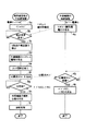
次に、以上のように構成された携帯通信端末の動作を、図3に示すフローチャートを用いて説明する。
なお、ここでは携帯通信端末MSに対し、USBのホスト機能を持つパーソナル・コンピュータPCを接続する場合と、USBのホスト機能を持たないメモリカードESを接続する場合をそれぞれ例にとって説明する。
【0039】
(1)パーソナル・コンピュータPCを接続する場合
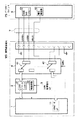
電源をオンした状態で、携帯通信端末MSに対しパーソナル・コンピュータPCを図4に示すようにUSBケーブル7を介して接続したとする。そうするとパーソナル・コンピュータPCは、ステップ4aにおいて、USB電源電圧を発生するために設けられた電圧発生器62によりUSB電源電圧(4.75〜5.25V)を発生する。このUSB電源電圧は、USBケーブル7及びUSB電源ピンP4(VBUS)を介して携帯通信端末MSに供給され、USBインタフェース2内の検出回路22に入力される。検出回路22は、上記電源電圧の入力を検出すると、ホストCPU1に対し割り込み信号を与える。
【0040】
携帯通信端末MSのホストCPU1は、ステップ3aでイニシャライズ処理を行ったのち、ステップ3bで割り込み信号の入力を監視している。この状態で、検出回路22から割り込み信号が入力されると、ホストCPU1はシステムコネクタ5に外部機器が接続されたものと判断し、ステップ3cで上記検出回路22から電圧検出値を入力したのち、この電圧検出値をもとにステップ3dで上記外部機器がUSBのホスト機能を持ったものであるか否かを判定する。
【0041】
例えば、電圧検出値がUSB電源電圧(4.75〜5.25V)だったとすれば、接続された外部機器はUSBのホスト機能を持った機器であると判定する。これに対し、電圧検出値が上記USB電源電圧(4.75〜5.25V)以外の電圧値(例えば2V)だったとすれば、接続された外部機器はUSBのホスト機能を持たない機器であると判定する。
【0042】
さて、そうして外部機器が保有する外部インタフェースの種別が判定されると、ホストCPU1はその判定結果に基づいてステップ3eでスイッチ回路4の切替制御を実行する。例えば、いまはUSBのホスト機能を持ったパーソナル・コンピュータPCを外部機器として接続しているため、ホストCPU1は図4に示すごとく、第1の切替スイッチ41をUSBデバイス・コントローラ21側に切り替えると共に、第2の切替スイッチ42をオフさせて、シリアルデータ・インタフェース11をシステムコネクタ5の製造者オプションピンP8及び予約ピンP9に対し非接続の状態に設定する。
【0043】
続いてホストCPU1は、ステップ3fに移行してここでID要求コマンド生成し、このID要求コマンドを上記USBデバイス・コントローラ21を介してパーソナル・コンピュータPCへ送信する。パーソナル・コンピュータPCは、図3に示すようにステップ4bでID要求コマンドの到来を監視しており、この状態で携帯通信端末MSからID要求コマンドが到来すると、ステップ4cにおいて自装置の種類を表すデバイスID及びメーカIDを生成し、これらのデバイスID及びメーカIDを携帯通信端末MSへ送信する。
【0044】
携帯通信端末MSのホストCPU1は、上記ID要求コマンドの送信後にステップ3gにおいてIDの到来を監視する。そして、この状態でデバイスID及びメーカIDが受信されると、ステップ3hにおいてこれらのデバイスID及びメーカIDをもとに図示しない外部機器データベースをアクセスして、外部機器の種類とその仕様を判定する。そして、この判定結果をもとに、ステップ3iで外部機器は自己の携帯通信端末MSに接続可能なものであるか否かを判定し、接続可能と判定した場合にはシステムコネクタ5と端末本体との間の接続ポートを有効状態に設定する。
【0045】
かくして、携帯通信端末MSとパーソナル・コンピュータPCとの間はUSBインタフェースを介して接続され、以後両デバイス間では上位プロトコルによるデータ転送制御が可能となる。
【0046】
(2)メモリカードESを接続する場合
携帯通信端末MSに対しメモリカードESを、図5に示すようにシステムコネクタ対応のケーブル9を介して接続したとする。そうするとメモリカードESは、ステップ4aにおいて、インタフェース識別用電圧を発生するために設けられた電圧発生器82により、予めUSB電源電圧(4.75〜5.25V)とは異なる値に設定された電源電圧(3V)を発生する。
【0047】
このインタフェース識別用電圧は、ケーブル9及びUSB電源ピンP4(VBUS)を介して携帯通信端末MSに供給され、USBインタフェース2内の検出回路22に入力される。検出回路22は、上記インタフェース識別用電圧の入力を検出すると、ホストCPU1に対し割り込み信号を与える。
【0048】
携帯通信端末MSのホストCPU1は、ステップ3bで割り込みの発生を検出すると、システムコネクタ5に外部機器が接続されたものと判断し、ステップ3cで上記検出回路22から電圧検出値を入力したのち、この電圧検出値をもとにステップ3dで上記外部機器がUSBのホスト機能を持ったものであるか否かを判定する。いまは、USB電源電圧(4.75〜5.25V)以外の電圧値(2V)であるため、接続された外部機器はUSBのホスト機能を持たない機器であると判定する。
【0049】
さて、そうして外部機器が保有する外部インタフェースの種別が判定されると、ホストCPU1はその判定結果に基づいてステップ3eでスイッチ回路4の切替制御を実行する。例えば、いまはUSBのホスト機能を持たないメモリカードESを外部機器として接続しているため、ホストCPU1は図5に示すごとく、第1の切替スイッチ41をシリアル制御信号インタフェース3側に切り替えると共に、第2の切替スイッチ42をオンさせてシリアルデータ・インタフェース11を、システムコネクタ5の製造者オプションピンP8及び予約ピンP9に接続させる。
【0050】
続いてホストCPU1は、ステップ3fに移行してここでID要求コマンド生成し、このID要求コマンドを上記シリアル制御信号インタフェース3を介してメモリカードESへ送信する。メモリカードESは、図3に示すようにステップ4bでID要求コマンドの到来を監視しており、この状態で携帯通信端末MSからID要求コマンドが到来すると、ステップ4cにおいて自装置の種類を表すデバイスID及びメーカIDを生成し、これらのデバイスID及びメーカIDを携帯通信端末MSへ送信する。
【0051】
携帯通信端末MSのホストCPU1は、上記ID要求コマンドの送信後にステップ3gにおいてIDの到来を監視する。そして、この状態でデバイスID及びメーカIDが受信されると、ステップ3hにおいてこれらのデバイスID及びメーカIDをもとに図示しない外部機器データベースをアクセスして、外部機器の種類とその仕様を判定する。そして、この判定結果をもとに、ステップ3iで外部機器は自己の携帯通信端末MSに接続可能なものであるか否かを判定し、接続可能と判定した場合にはシステムコネクタ5と端末本体との間の接続ポートを有効状態に設定する。
【0052】
かくして、携帯通信端末MSとメモリカードESとの間はシリアル制御信号インタフェース3,81及びシリアルデータ・インタフェース11,83を介して接続され、以後両デバイス間では上位プロトコルによるシリアルデータ転送が可能となる。
【0053】
これに対し、上記外部機器の種類とその仕様の判定結果をもとに、外部機器は自己の携帯通信端末MSに接続不可能なものであると判定した場合には、システムコネクタ5と端末本体との間の接続ポートを遮断状態に設定する。したがって、携帯通信端末MSに対し仕様が適合しない外部機器が接続された場合には、この外部機器の接続は遮断され、この結果携帯通信端末MSに対する外部機器による悪影響は未然に防止される。
【0054】
以上述べたようにこの実施形態では、携帯通信端末MSにおいて、USBデバイス・コントローラ21を持つUSBインタフェース2に加え、シリアル制御信号インタフェース3及びシリアルデータ・インタフェース11を設けると共に、これらのインタフェースを選択的にシステムコネクタ5に接続するスイッチ回路4を設けている。そして、システムコネクタ5に外部機器が接続されたとき、この外部機器から供給されるインタフェース識別用電圧をもとに、外部機器がUSBのホスト機能を有する外部インタフェースを持っているか否かを判定し、この判定結果をもとにスイッチ回路4を切替制御して適当な外部インタフェースを選択するようにしている。
【0055】
したがって、接続された外部機器がUSBのホスト機能を持っているパーソナル・コンピュータPCの場合にはUSBインタフェース2が選択されて、USBインタフェースを使用したデータ転送が行われ、一方外部機器がUSBのホスト機能を持っていないメモリカードES等のスレーブ・デバイスの場合にはシリアル制御信号インタフェース3及びシリアルデータ・インタフェース11が選択されて、汎用のシリアルインタフェースを使用したデータ転送が行われる。
【0056】
すなわち、携帯通信端末MSにUSBのホスト機能を持たせなくても、外部インタフェースの異なる複数種の外部機器を選択的に接続してデータ転送を行うことができ、これにより携帯通信端末MSを低消費電力及び低価格に維持することができる。
【0057】
またこの実施形態では、1個のシリアルコネクタ5に対し、USBインタフェースとシリアルインタフェースとを選択的に接続するようにしている。すなわち、1個のシリアルコネクタ5をUSBインタフェースとシリアルインタフェースとで共用している。このため、新たにシリアルインタフェース用のコネクタを設ける必要がなく、この結果携帯通信端末の大型化を防止することができる。
【0058】
さらにこの実施形態では、接続された外部機器との間で認証手順を実行して外部機器のデバイス種別とメーカ名、つまり仕様を判定し、この判定結果をもとに当該外部機器が自端末に接続可能な機器であるか否かを判定する。そして、接続不可能な機器であると判定された場合には、外部機器を非接続状態に設定するようにしている。
したがって、仕様が異なる外部機器が接続されても、この外部機器によって携帯通信端末が誤動作や故障を起こす不具合は未然に防止される。
【0059】
この効果は、外部機器として例えば充電器を接続した場合に特に有効である。
すなわち、接続された充電器の電圧/電流の定格値が携帯通信端末の規格値と異なると、場合によっては発熱や発火を起こすことがありきわめて好ましくない。そこでこの実施形態では、外部機器としての充電器が接続されたときに、認証手順により取得した充電器のデバイスID及びメーカIDをもとにその仕様を判定し、この判定の結果当該充電器が接続不可能と判定された場合には、充電用電源入力ピンP5,P6と携帯通信端末内の電源回路との間を遮断して充電が行われないようにしている。したがって、規格の異なる充電器が接続されたとしても、発熱や発火を起こす不具合は確実に防止される。
【0060】
なお、この発明は上記実施形態に限定されるものではない。例えば、前記実施形態ではUSBのスレーブ機能を持ったUSBインタフェースと、汎用のシリアルインタフェースとを備え、接続された外部機器が持つ外部インタフェースの種類に応じてこれらの外部インタフェースを選択する構成とした。しかし、必ずしもこれに限定されるものではなく、RS232CやSPI、I2BUS、IEEE1394等のその他の外部インタフェースを複数種備え、これらの外部インタフェースを外部機器が持つ外部インタフェースの種類に応じて選択するように構成してもよい。
【0061】
また、前記実施形態では、携帯通信端末MSにUSBスレーブ機能を有するUSBインタフェースを備えた場合を例にとって説明したが、例えばパーソナル・コンピュータ等の処理能力の高い外部機器に備えられるUSBホスト機能よりも処理付加が小さくなるように構成したUSBの簡易ホスト機能を携帯通信端末MSに設けるように構成してもよい。
このようにすることで、携帯通信端末MSのメモリ容量及びCPUの処理能力をそれほど高めずに、USBスレーブ機能しか持たない大半の外部機器との間でUSBインタフェースを使用したデータ転送を行うことが可能となる。
【0062】
さらに、前記実施形態では外部機器が有する外部インタフェースの種別判定を、外部機器が発生するインタフェース識別用電圧をもとに行うようにしたが、インタフェース識別用電圧の代わりに1ビット又は2ビット程度の識別信号を用い、この識別信号を外部機器から携帯通信端末の特定のコネクタピンに供給することにより、外部インタフェースの種別判定を行うように構成してもよい。
【0063】
その他、第1及び第2の判定手段の構成や判定内容、インタフェース選択手段の構成、接続制御手段の構成、外部機器の種類や外部インタフェースの種類等についても、この発明の要旨を逸脱しない範囲で種々変形して実施できる。
【0064】
【発明の効果】
以上詳述したようにこの発明では、USBのホスト機能と、シリアル制御信号インタフェース機能及びシリアルデータ・インタフェース機能とのうち少なくとも一方を有する外部インタフェースを備えた外部機器に対し接続される携帯通信端末にあって、USB(Universal Serial Bus)端子と所定の付加端子とを備える1個の外部接続用コネクタと、USBのスレーブ機能を有し外部機器との間で前記外部接続用コネクタを介して信号を授受するUSBスレーブ・インタフェースと、外部機器との間で前記外部接続用コネクタを介してシリアル制御信号を授受するシリアル制御信号インタフェースと、外部機器との間で前記外部接続用コネクタを介してシリアルデータを授受するシリアルデータ・インタフェースと、前記外部接続用コネクタに接続された外部機器が備える外部インタフェースがUSBのホスト機能を有しているか否かを判定する第1の判定手段と、インタフェース選択手段とを備えている。
さらにインタフェース選択手段には、上記USBスレーブ・インタフェース及び上記シリアル制御信号インタフェースを上記外部接続コネクタのUSB端子に対し択一的に接続する第1の切替スイッチと、上記外部接続用コネクタの付加端子に対する上記シリアルデータ・インタフェースの接続をオンオフする第2の切替スイッチと、制御回路とを設け、この制御回路により、上記第1の判定手段により上記外部機器が備える外部インタフェースがUSBのホスト機能を有していると判定された場合には、上記第1の切替スイッチにより上記USBスレーブ・インタフェースを上記外部接続用コネクタに接続させると共に、上記第2の切替スイッチにより上記シリアルデータ・インタフェースを上記外部接続用コネクタから切り離し、一方上記第1の判定手段により上記外部インタフェースがUSBのホスト機能を有していないと判定された場合には、上記第1の切替スイッチにより上記シリアル制御信号インタフェースを上記外部接続用コネクタに接続させると共に、上記第2の切替スイッチにより上記シリアルデータ・インタフェースを上記外部接続用コネクタに接続させるように、上記第1及び第2の切替スイッチを制御するように構成している。
【0065】
したがってこの発明によれば、大容量のメモリや処理能力の高いCPUさらには複数種のコネクタを設けることなく外部機器を接続することができ、これにより消費電力が小さく安価でかつ小型化の容易な携帯通信端末を提供することができる。
【図面の簡単な説明】
【図1】 この発明に係わる携帯通信端末の一実施形態を示す要部構成図。
【図2】 図1に示した携帯通信端末に設けられるシステムコネクタの各ピンの名前と機能を示す図。
【図3】 図1に示した携帯通信端末及びこの携帯通信端末に接続される外部機器の接続制御手順とその内容を示すフローチャート。
【図4】 図1に示す携帯通信端末にUSBのホスト機能を持つパーソナル・コンピュータを外部機器として接続とした場合の接続構成を示す図。
【図5】 図1に示す携帯通信端末にUSBのホスト機能を持たないメモリカードを外部機器として接続とした場合の接続構成を示す図。
【符号の説明】
MS…携帯通信端末
PC…パーソナル・コンピュータ
ES…メモリカード
1…携帯通信端末のホストCPU
1a…第1の判定手段
1b…インタフェース選択制御手段
1c…第2の判定手段
1d…接続制御手段
2…USBインタフェース
3,81…シリアル制御信号インタフェース
4…スイッチ回路
5…システムコネクタ
6…パーソナル・コンピュータのホストCPU
7…USBケーブル
8…メモリカードのホストCPU
11,83…シリアルデータ・インタフェース
21…USBデバイス・コントローラ
22…インタフェース識別用電圧の検出回路
41…第1の切替スイッチ
42…第2の切替スイッチ
61…USBホストコントローラ
62,82…電圧発生器[0001]
BACKGROUND OF THE INVENTION
The present invention relates to a portable communication terminal used in a mobile communication system adopting, for example, a W-CDMA (Wideband-Code Division Multiple Access) system.
[0002]
[Prior art]
The W-CDMA system has been standardized as a system for realizing the next-generation mobile phone system, and various developments of communication devices used in this type of system are currently underway.
[0003]
For example, it is proposed that a portable communication terminal is provided with a connector having a USB (Universal Serial Bus) terminal. Using a USB interface as an external connection interface, you can easily connect a mobile communication terminal to a personal computer, and easily connect external devices such as a BT (Bluetooth) unit, memory card, and keyboard to the mobile communication terminal. can do. Then, management data such as a telephone directory is transferred from the personal computer to the mobile communication terminal and registered in a batch, or the functions of the mobile communication terminal are appropriately selected by selectively using the various external devices as necessary. It becomes possible to expand.
[0004]
However, when signal transfer is performed between a plurality of devices using a USB interface, it is necessary to provide at least one device with a USB host function. Because this USB host function has a heavy processing load, it is usually given to a device with a high processing capacity such as a personal computer. On the other hand, peripheral devices such as keyboards and mice, as well as small devices such as portable communication terminals, have a USB slave function. It is common to have For this reason, even if an external device such as a BT (Bluetooth) unit, a memory card, or a keyboard is connected to the mobile communication terminal, both have only a USB slave function, and therefore a connection using a USB interface may be performed. Can not.
[0005]
In order to solve this, the portable communication terminal may have a USB host function.
However, if this is done, it is necessary to provide the mobile communication terminal with a large-capacity memory and a CPU with a high processing capability, resulting in an increase in power consumption and cost increase of the mobile communication terminal.
[0006]
On the other hand, instead of providing the portable communication terminal with a USB host function, it is conceivable to provide other general-purpose interfaces such as a serial interface. In this way, it is not necessary to provide a large-capacity memory or a CPU with high processing capability in the mobile communication terminal. However, it is necessary to provide a serial interface connector in addition to the connector having the USB terminal, which is a major obstacle to miniaturization of the portable communication terminal.
[0007]
[Problems to be solved by the invention]
As described above, the mobile communication terminal for W-CDMA, which is currently being developed, cannot connect to an external device via USB. In order to realize USB connection, it is necessary to provide a portable communication terminal with a large-capacity memory and a CPU with high processing capacity, or a connector for a serial interface in addition to a connector having a USB terminal. There is a problem that increase in power consumption, cost increase, and enlargement of the terminal cannot be avoided.
[0008]
This invention was made paying attention to the above circumstances, and its purpose is to enable connection of external devices without providing a large-capacity memory, a CPU with high processing capability, and more than one type of connector, Accordingly, an object of the present invention is to provide a portable communication terminal that is low in power consumption, inexpensive, and easy to downsize.
[0009]
[Means for Solving the Problems]
In order to achieve the above object, the present invention provides a USB host function and Serial control signal interface function and Serial data interface function When A portable communication terminal connected to an external device having an external interface having at least one of them, a single external connection connector having a USB (Universal Serial Bus) terminal and a predetermined additional terminal, and a USB USB slave interface that has a slave function and exchanges signals with external devices via the external connection connector, and serial control signals with external devices via the external connection connector A serial control signal interface, a serial data interface for transferring serial data to and from an external device via the external connection connector, and an external interface included in the external device connected to the external connection connector is a USB host A first determination means for determining whether or not a function is present, and an interface selector It is equipped with a door.
Further, the interface selection means includes a first changeover switch for selectively connecting the USB slave interface and the serial control signal interface to the USB terminal of the external connection connector, and an additional terminal of the external connection connector. A second changeover switch for turning on / off the connection of the serial data interface and a control circuit are provided, and the external interface provided in the external device by the first determination means has a USB host function by the control circuit. If it is determined that the USB slave interface is connected to the external connection connector by the first switch, the serial data interface is connected to the external connection by the second switch. Disconnect from connector, up one side When the first determination unit determines that the external interface does not have a USB host function, the first control switch connects the serial control signal interface to the external connection connector, and The first and second changeover switches are controlled so that the serial data interface is connected to the external connector by the second changeover switch.
[0011]
Therefore, according to the present invention, if the external device is a device having a USB host function such as a personal computer, the USB slave interface is selected and the USB connection is performed, while the external device is, for example, a BT unit. In the case of a device that does not have a USB host function, such as a memory card or a keyboard, a general-purpose external interface such as a serial interface is selected and connected. For this reason, it is not necessary to provide a USB host interface in the mobile communication terminal, and as a result, a large-capacity memory and a CPU with high processing capacity are not required, and an increase in power consumption and cost increase of the mobile communication terminal is prevented. The
[0012]
Also, when a USB connection is selected or when another general-purpose external interface is selected, one connector having a USB terminal is used. For this reason, it is not necessary to provide, for example, a serial interface connector separately from the connector having the USB terminal, and thus the size of the portable communication terminal can be maintained.
[0013]
The present invention also executes an authentication procedure with an external device via the interface selected by the interface selection means to determine the type and specification of the external device, and based on the determination result, the external device It is determined whether or not the device is connectable to the own terminal. When it is determined that the external device is a device that can be connected to the own terminal, the connection of the external device to the own terminal is set to a valid state, and the external device is a device that cannot be connected to the own terminal. The method further includes means for blocking the connection of the external device to the terminal if it is determined.
[0015]
Therefore, according to the second aspect of the invention, the connection form of the external device to the own terminal is determined based on the authentication result with the external device. For example, based on the type of external device and its specifications, it is determined whether or not the external device can be connected to the own terminal. For this reason, even if the external interface is compatible, if the specifications of the external device are different, it can be controlled not to allow the connection of this external device, thereby always connecting the external device with high reliability. be able to.
[0016]
The first and second inventions are characterized in that at least one of the determination result by the first determination means and the determination result by the second determination means is displayed on the display means.
[0017]
In this way, the user of the mobile communication terminal can check the type of the external interface of the external device or the connection form of the external device to the own terminal. In the case of equipment, this can be recognized.
[0022]
DETAILED DESCRIPTION OF THE INVENTION
An embodiment of the present invention will be described below with reference to the drawings.
FIG. 1 shows an embodiment of a portable communication terminal according to the present invention. The mobile communication terminal of this embodiment includes a host CPU 1, a USB interface 2, a serial
[0023]
First of all, the system connector 5 is for connecting an external device (not shown) to its own portable communication terminal, and has a total of 11 terminals (pins) P1 to P10 and PRF. FIG. 2 shows the names and functions of these pins P1 to P10 and PRF.
[0024]
Of all 11 pins P1 to P10 and PRF, pins P1 to P4 are used for USB connection. Among these, P2 and P3 are USB data transfer pins USBD + and USBD-, respectively, and bidirectional transfer of data is performed between these pins and an external device (not shown). P4 is a USB power input pin to which a USB power voltage (4.75 to 5.25 V) supplied from an external device is input. P1 is a USB ground pin.
[0025]
Of all the 11 pins P1 to P10 and PRF, pins P5 and P6 are charging power input pins, and charge voltage and current supplied from a charger which is one of external devices are supplied to a battery circuit (not shown). Supply. The pin P7 is a synchronous clock output pin, and outputs synchronous clock (64 kHz) to the external device when performing synchronous communication with the external device. The electrical condition of the synchronous clock output pin P7 is CMOS 2V ± 0.2V, and is set to high impedance (200 kΩ or more) when not in use.
[0026]
Furthermore, the pins P8 and P9 are a manufacturer option pin and a reserved pin, respectively. In this embodiment, serial data is transferred to and from an external device using these pins P8 and P9. The electrical condition of the manufacturer option pin is defined so that the input voltage is 3.6 V or less, and is set to high impedance (200 kΩ or more) when not in use.
[0027]
The USB interface 2 includes a
[0028]
The
[0029]
The serial
[0030]
The host CPU 1 is provided with a
[0031]
By the way, a switch circuit 4 is installed between each of the external interfaces, that is, the USB interface 2, the serial
[0032]
The
[0033]
The host CPU 1 includes a
[0034]
First of all, the first determination means 1a takes in the detected value of the interface identification voltage from the
[0035]
The interface
[0036]
The second determination means 1c is connected to the
[0037]
The
[0038]
Next, the operation of the mobile communication terminal configured as described above will be described using the flowchart shown in FIG.
Here, a case where a personal computer PC having a USB host function and a memory card ES not having a USB host function are connected to the mobile communication terminal MS will be described as examples.
[0039]
(1) When connecting a personal computer PC
Assume that a personal computer PC is connected to the mobile communication terminal MS via the USB cable 7 as shown in FIG. Then, in
[0040]
The host CPU 1 of the mobile communication terminal MS monitors the input of an interrupt signal in
[0041]
For example, if the detected voltage value is a USB power supply voltage (4.75 to 5.25 V), it is determined that the connected external device is a device having a USB host function. On the other hand, if the voltage detection value is a voltage value (for example, 2 V) other than the USB power supply voltage (4.75 to 5.25 V), the connected external device is a device that does not have a USB host function. Is determined.
[0042]
When the type of the external interface held by the external device is determined in this way, the host CPU 1 executes switching control of the switch circuit 4 in
[0043]
Subsequently, the host CPU 1 proceeds to step 3 f to generate an ID request command here, and transmits this ID request command to the personal computer PC via the
[0044]
The host CPU 1 of the mobile communication terminal MS monitors the arrival of the ID in
[0045]
Thus, the portable communication terminal MS and the personal computer PC are connected via the USB interface, and thereafter, data transfer control by the upper protocol is possible between both devices.
[0046]
(2) When connecting a memory card ES
It is assumed that the memory card ES is connected to the mobile communication terminal MS via a
[0047]
The interface identification voltage is supplied to the mobile communication terminal MS via the
[0048]
When the host CPU 1 of the mobile communication terminal MS detects the occurrence of an interrupt in
[0049]
When the type of the external interface held by the external device is determined in this way, the host CPU 1 executes switching control of the switch circuit 4 in
[0050]
Subsequently, the host CPU 1 proceeds to step 3f to generate an ID request command here, and transmits the ID request command to the memory card ES via the serial
[0051]
The host CPU 1 of the mobile communication terminal MS monitors the arrival of the ID in
[0052]
Thus, the mobile communication terminal MS and the memory card ES are connected via the serial
[0053]
On the other hand, if it is determined that the external device cannot be connected to the mobile communication terminal MS based on the determination result of the type of external device and its specification, the system connector 5 and the terminal body Set the connection port between and to the blocked state. Therefore, when an external device that does not conform to the specifications is connected to the mobile communication terminal MS, the connection of the external device is blocked, and as a result, adverse effects of the external device on the mobile communication terminal MS are prevented.
[0054]
As described above, in this embodiment, in the mobile communication terminal MS, in addition to the USB interface 2 having the
[0055]
Therefore, when the connected external device is a personal computer PC having a USB host function, the USB interface 2 is selected and data transfer is performed using the USB interface, while the external device is a USB host. In the case of a slave device such as a memory card ES having no function, the serial
[0056]
That is, even if the portable communication terminal MS is not provided with a USB host function, data can be transferred by selectively connecting a plurality of types of external devices having different external interfaces, thereby reducing the portable communication terminal MS. Power consumption and low price can be maintained.
[0057]
In this embodiment, a USB interface and a serial interface are selectively connected to one serial connector 5. That is, one serial connector 5 is shared by the USB interface and the serial interface. For this reason, it is not necessary to newly provide a connector for a serial interface, and as a result, an increase in the size of the portable communication terminal can be prevented.
[0058]
Further, in this embodiment, the authentication procedure is executed with the connected external device to determine the device type and manufacturer name of the external device, that is, the specification, and based on the determination result, the external device is set as its own terminal. It is determined whether it is a connectable device. When it is determined that the device cannot be connected, the external device is set to a non-connected state.
Therefore, even when an external device having a different specification is connected, a malfunction that causes the mobile communication terminal to malfunction or break down due to the external device can be prevented.
[0059]
This effect is particularly effective when, for example, a charger is connected as an external device.
That is, if the rated value of the voltage / current of the connected charger is different from the standard value of the mobile communication terminal, it may cause heat generation or fire in some cases, which is extremely undesirable. Therefore, in this embodiment, when a charger as an external device is connected, the specification is determined based on the device ID and manufacturer ID of the charger acquired by the authentication procedure. As a result of the determination, the charger is When it is determined that the connection is impossible, the charging power input pins P5 and P6 and the power supply circuit in the portable communication terminal are disconnected to prevent charging. Therefore, even if chargers with different standards are connected, problems that cause heat generation or ignition are reliably prevented.
[0060]
The present invention is not limited to the above embodiment. For example, in the above-described embodiment, a USB interface having a USB slave function and a general-purpose serial interface are provided, and these external interfaces are selected according to the type of external interface of the connected external device. However, the present invention is not necessarily limited to this. A plurality of other external interfaces such as RS232C, SPI, I2BUS, IEEE1394, etc. are provided, and these external interfaces are selected according to the type of external interface possessed by the external device. It may be configured.
[0061]
In the embodiment, the case where the mobile communication terminal MS is provided with a USB interface having a USB slave function has been described as an example. However, for example, the portable communication terminal MS is more than a USB host function provided in an external device having a high processing capability such as a personal computer. A USB simple host function configured to reduce processing addition may be provided in the mobile communication terminal MS.
In this way, data transfer using the USB interface can be performed with most external devices having only a USB slave function without significantly increasing the memory capacity of the mobile communication terminal MS and the processing capacity of the CPU. It becomes possible.
[0062]
Furthermore, in the embodiment, the type of the external interface included in the external device is determined based on the interface identification voltage generated by the external device. However, instead of the interface identification voltage, about 1 bit or 2 bits are used. The identification signal may be used, and the identification signal may be supplied from an external device to a specific connector pin of the mobile communication terminal to determine the type of the external interface.
[0063]
In addition, the configurations and determination contents of the first and second determination units, the configuration of the interface selection unit, the configuration of the connection control unit, the types of external devices, the types of external interfaces, and the like are within the scope of the present invention. Various modifications can be made.
[0064]
【The invention's effect】
As described above in detail, in the present invention, the USB host function and Serial control signal interface function and Serial data interface function When A portable communication terminal connected to an external device having an external interface having at least one of them, a single external connection connector having a USB (Universal Serial Bus) terminal and a predetermined additional terminal, and a USB USB slave interface that has a slave function and exchanges signals with external devices via the external connection connector, and serial control signals with external devices via the external connection connector A serial control signal interface, a serial data interface for transferring serial data to and from an external device via the external connection connector, and an external interface included in the external device connected to the external connection connector is a USB host A first determination means for determining whether or not a function is present, and an interface selector It is equipped with a door.
Further, the interface selection means includes a first changeover switch for selectively connecting the USB slave interface and the serial control signal interface to the USB terminal of the external connection connector, and an additional terminal of the external connection connector. A second changeover switch for turning on / off the connection of the serial data interface and a control circuit are provided, and the external interface provided in the external device by the first determination means has a USB host function by the control circuit. If it is determined that the USB slave interface is connected to the external connection connector by the first switch, the serial data interface is connected to the external connection by the second switch. Disconnect from connector, up one side When the first determination unit determines that the external interface does not have a USB host function, the first changeover switch connects the serial control signal interface to the external connection connector, The first and second selector switches are controlled so that the serial data interface is connected to the external connector by the second selector switch.
[0065]
Therefore, according to the present invention, an external device can be connected without providing a large-capacity memory, a CPU with high processing capability, and a plurality of types of connectors. A mobile communication terminal can be provided.
[Brief description of the drawings]
FIG. 1 is a main part configuration diagram showing an embodiment of a mobile communication terminal according to the present invention.
FIG. 2 is a view showing names and functions of pins of a system connector provided in the mobile communication terminal shown in FIG. 1;
FIG. 3 is a flowchart showing a connection control procedure and contents of the mobile communication terminal shown in FIG. 1 and an external device connected to the mobile communication terminal.
4 is a diagram showing a connection configuration when a personal computer having a USB host function is connected as an external device to the mobile communication terminal shown in FIG. 1;
FIG. 5 is a diagram showing a connection configuration when a memory card not having a USB host function is connected as an external device to the mobile communication terminal shown in FIG. 1;
[Explanation of symbols]
MS ... Mobile communication terminal
PC ... Personal computer
ES ... Memory card
1 ... Host CPU of portable communication terminal
1a: First determining means
1b: Interface selection control means
1c ... Second determination means
1d: Connection control means
2 ... USB interface
3, 81 ... Serial control signal interface
4 ... Switch circuit
5 ... System connector
6 ... Host CPU of personal computer
7 ... USB cable
8 ... Host CPU of memory card
11, 83 ... Serial data interface
21 ... USB device controller
22 ... Voltage detection circuit for interface identification
41 ... 1st changeover switch
42 ... Second changeover switch
61 ... USB host controller
62, 82 ... Voltage generator
Claims (4)
USB(Universal Serial Bus)端子と所定の付加端子とを備える1個の外部接続用コネクタと、
USBのスレーブ機能を有し外部機器との間で前記外部接続用コネクタを介して信号を授受するUSBスレーブ・インタフェースと、
外部機器との間で前記外部接続用コネクタを介してシリアル制御信号を授受するシリアル制御信号インタフェースと、
外部機器との間で前記外部接続用コネクタを介してシリアルデータを授受するシリアルデータ・インタフェースと、
前記外部接続用コネクタに接続された外部機器が備える外部インタフェースがUSBのホスト機能を有しているか否かを判定する第1の判定手段と、
インタフェース選択手段と
を具備し、
前記インタフェース選択手段は、
前記USBスレーブ・インタフェース及び前記シリアル制御信号インタフェースを前記外部接続コネクタのUSB端子に対し択一的に接続する第1の切替スイッチと、
前記外部接続用コネクタの付加端子に対する前記シリアルデータ・インタフェースの接続をオンオフする第2の切替スイッチと、
前記第1の判定手段により前記外部機器が備える外部インタフェースがUSBのホスト機能を有していると判定された場合には、前記第1の切替スイッチにより前記USBスレーブ・インタフェースを前記外部接続用コネクタに接続させると共に、前記第2の切替スイッチにより前記シリアルデータ・インタフェースを前記外部接続用コネクタから切り離し、前記第1の判定手段により前記外部インタフェースがUSBのホスト機能を有していないと判定された場合には、前記第1の切替スイッチにより前記シリアル制御信号インタフェースを前記外部接続用コネクタに接続させると共に、前記第2の切替スイッチにより前記シリアルデータ・インタフェースを前記外部接続用コネクタに接続させるように、前記第1及び第2の切替スイッチを制御する制御手段と
を備えることを特徴とする携帯通信端末。A portable communication terminal connected to an external device having an external interface having at least one of a USB host function, a serial control signal interface function, and a serial data interface function,
One external connection connector having a USB (Universal Serial Bus) terminal and a predetermined additional terminal;
A USB slave interface which has a USB slave function and exchanges signals with external devices via the external connection connector;
A serial control signal interface that exchanges serial control signals with external devices via the external connection connector;
A serial data interface that exchanges serial data with an external device via the external connection connector;
First determination means for determining whether or not an external interface included in an external device connected to the external connection connector has a USB host function;
Interface selection means,
The interface selection means includes
A first changeover switch for selectively connecting the USB slave interface and the serial control signal interface to a USB terminal of the external connector;
A second changeover switch for turning on / off the connection of the serial data interface to the additional terminal of the external connection connector;
When it is determined by the first determination means that the external interface provided in the external device has a USB host function, the USB slave interface is connected to the external connection connector by the first changeover switch. And the second changeover switch disconnects the serial data interface from the external connector, and the first determination means determines that the external interface does not have a USB host function. In this case, the serial control signal interface is connected to the external connection connector by the first changeover switch, and the serial data interface is connected to the external connection connector by the second changeover switch. The first and second changeover switches Mobile communication terminal; and a control means for controlling.
この第2の判定手段により、前記外部機器が自端末に対し接続可能な機器であると判定された場合に、前記外部接続用コネクタと前記携帯通信端末本体との間の接続を維持し、一方前記外部機器が自端末に対し接続不可能な機器であると判定された場合には、前記外部接続用コネクタと前記携帯通信端末本体との間の接続を電気的に切り離す手段と
を、さらに具備したことを特徴とする請求項1記載の携帯通信端末。Subsequent to the connection processing operation by the interface selection unit, device identification information and manufacturer identification information indicating the type of the external device from the external device via the USB slave interface or serial control signal interface selected by the interface selection unit Based on the received device identification information and manufacturer identification information, the external device database provided in advance is accessed to determine the type of external device and its specifications, and the type of external device and its Second determination means for determining whether the external device is a device connectable to the own terminal or a non-connectable device based on a determination result of the specification ;
When the second determination means determines that the external device is a device connectable to the terminal, the connection between the external connection connector and the mobile communication terminal body is maintained. Means for electrically disconnecting the connection between the external connection connector and the mobile communication terminal main body when it is determined that the external device is a device that cannot be connected to the terminal; The mobile communication terminal according to claim 1, wherein
USB(Universal Serial Bus)端子と所定の付加端子とを備える1個の外部接続用コネクタと、
USBのスレーブ機能を有し外部機器との間で前記外部接続用コネクタを介して信号を授受するUSBスレーブ・インタフェースと、
外部機器との間で前記外部接続用コネクタを介してシリアル制御信号を授受するシリアル制御信号インタフェースと、
外部機器との間で前記外部接続用コネクタを介してシリアルデータを授受するシリアルデータ・インタフェースと、
前記外部接続用コネクタに接続された外部機器が備える外部インタフェースがUSBのホスト機能を有しているか否かを判定する第1の判定手段と、
前記第1の判定手段により前記外部機器が備える外部インタフェースがUSBのホスト機能を有していると判定された場合には前記USBスレーブ・インタフェースを選択して前記外部接続用コネクタのUSB端子に接続すると共に前記シリアルデータ・インタフェースを前記外部接続用コネクタの付加端子から切り離し、前記外部インタフェースがUSBのホスト機能を有していないと判定された場合には前記シリアル制御信号インタフェースを前記外部接続用コネクタのUSB端子に接続すると共に前記シリアルデータ・インタフェースを前記外部接続用コネクタの付加端子に接続するインタフェース選択手段と
を具備したことを特徴とする携帯通信端末。 A portable communication terminal connected to an external device having an external interface having at least one of a USB host function, a serial control signal interface function, and a serial data interface function,
One external connection connector having a USB (Universal Serial Bus) terminal and a predetermined additional terminal;
A USB slave interface which has a USB slave function and exchanges signals with external devices via the external connection connector;
A serial control signal interface that exchanges serial control signals with external devices via the external connection connector;
A serial data interface that exchanges serial data with an external device via the external connection connector;
First determination means for determining whether or not an external interface included in an external device connected to the external connection connector has a USB host function;
When the first determination unit determines that the external interface included in the external device has a USB host function, the USB slave interface is selected and connected to the USB terminal of the external connection connector When the serial data interface is disconnected from the additional terminal of the external connection connector and it is determined that the external interface does not have a USB host function, the serial control signal interface is connected to the external connection connector. And an interface selection means for connecting the serial data interface to the additional terminal of the external connection connector.
Priority Applications (4)
| Application Number | Priority Date | Filing Date | Title |
|---|---|---|---|
| JP2000124493A JP4659175B2 (en) | 2000-04-25 | 2000-04-25 | Mobile communication terminal |
| US09/810,658 US6836814B2 (en) | 2000-04-25 | 2001-03-19 | Mobile communication terminal device |
| EP01106938A EP1150525B1 (en) | 2000-04-25 | 2001-03-20 | Mobile communication terminal device |
| DE60137165T DE60137165D1 (en) | 2000-04-25 | 2001-03-20 | Mobile communication terminal |
Applications Claiming Priority (1)
| Application Number | Priority Date | Filing Date | Title |
|---|---|---|---|
| JP2000124493A JP4659175B2 (en) | 2000-04-25 | 2000-04-25 | Mobile communication terminal |
Related Child Applications (1)
| Application Number | Title | Priority Date | Filing Date |
|---|---|---|---|
| JP2008155525A Division JP2008276794A (en) | 2008-06-13 | 2008-06-13 | Portable communication terminal |
Publications (3)
| Publication Number | Publication Date |
|---|---|
| JP2001306495A JP2001306495A (en) | 2001-11-02 |
| JP2001306495A5 JP2001306495A5 (en) | 2007-02-08 |
| JP4659175B2 true JP4659175B2 (en) | 2011-03-30 |
Family
ID=18634623
Family Applications (1)
| Application Number | Title | Priority Date | Filing Date |
|---|---|---|---|
| JP2000124493A Expired - Fee Related JP4659175B2 (en) | 2000-04-25 | 2000-04-25 | Mobile communication terminal |
Country Status (4)
| Country | Link |
|---|---|
| US (1) | US6836814B2 (en) |
| EP (1) | EP1150525B1 (en) |
| JP (1) | JP4659175B2 (en) |
| DE (1) | DE60137165D1 (en) |
Families Citing this family (75)
| Publication number | Priority date | Publication date | Assignee | Title |
|---|---|---|---|---|
| US6601124B1 (en) * | 2000-02-14 | 2003-07-29 | International Business Machines Corporation | Universal interface for selectively coupling to a computer port type and method therefor |
| JP3497834B2 (en) * | 2001-03-30 | 2004-02-16 | 株式会社東芝 | Route repeater, USB communication system, USB communication control method |
| GB2375273B (en) * | 2001-04-30 | 2004-07-07 | Nokia Mobile Phones Ltd | Communication interface for an electronic device |
| JP2003008683A (en) * | 2001-06-18 | 2003-01-10 | Nec Corp | Cellular phone apparatus with usb reconnection function, and communication recovery method of the device |
| JP2003158561A (en) * | 2001-11-21 | 2003-05-30 | Nec Corp | Mobile phone |
| JP3734448B2 (en) * | 2002-01-18 | 2006-01-11 | パイオニア株式会社 | charging cable |
| KR20040016595A (en) * | 2002-08-19 | 2004-02-25 | 에스케이텔레텍주식회사 | Mobile phone for cable data communication |
| JP2004102331A (en) * | 2002-09-04 | 2004-04-02 | Renesas Technology Corp | Semiconductor device |
| US20040063464A1 (en) * | 2002-09-30 | 2004-04-01 | Tahir Akram | High-speed data and power source interface cable for mobile devices |
| GB2394080A (en) * | 2002-10-10 | 2004-04-14 | Nokia Corp | USB host device which relinquishes host status upon detection of elevated bus voltage |
| KR100516296B1 (en) | 2003-01-21 | 2005-09-21 | 주식회사 팬택앤큐리텔 | Usb interface device by using function of switch |
| US20040143693A1 (en) * | 2003-01-21 | 2004-07-22 | Denny Hwang | Data storage apparatus of multiple serial interfaces |
| DE20312002U1 (en) * | 2003-08-02 | 2003-10-30 | Power 7 Technology Corp | Digital data transmission device |
| JP2005079722A (en) * | 2003-08-28 | 2005-03-24 | Kyocera Corp | Information equipment apparatus |
| KR100979110B1 (en) | 2003-09-23 | 2010-08-31 | 엘지전자 주식회사 | Apparatus and method for controlling USB device interface in personal digital assistant |
| US7032052B2 (en) * | 2004-01-15 | 2006-04-18 | Dell Products L.P. | Information handling system capable of operating with multiple types of expansion cards in a common industry standard connector |
| US20090024757A1 (en) * | 2004-07-30 | 2009-01-22 | Proctor David W | Automatic Protocol Determination For Portable Devices Supporting Multiple Protocols |
| TWI244607B (en) * | 2004-08-27 | 2005-12-01 | Incomm Technologies Co Ltd | Multi-interface auto-switching circuit and memory device having the same |
| EP1825381A1 (en) * | 2004-12-15 | 2007-08-29 | Viamichelin | Interface device |
| US7823214B2 (en) * | 2005-01-07 | 2010-10-26 | Apple Inc. | Accessory authentication for electronic devices |
| KR100686877B1 (en) | 2005-01-31 | 2007-02-23 | 엘지전자 주식회사 | USB system providing function of USB host and device |
| US8913634B2 (en) * | 2005-04-01 | 2014-12-16 | Freescale Semiconductor, Inc. | Method and apparatus facilitating multi mode interfaces |
| EP1717910B1 (en) | 2005-04-27 | 2011-12-14 | LG Electronics Inc. | Mobile communications terminal using multi-functional socket and method thereof |
| ES2377222T3 (en) * | 2005-04-27 | 2012-03-23 | Lg Electronics Inc. | Mobile communications terminal with multifunctional connection socket and corresponding method |
| JP2006343815A (en) * | 2005-06-07 | 2006-12-21 | Matsushita Electric Ind Co Ltd | Communication device, communication method, and communication system |
| KR100770856B1 (en) | 2005-06-16 | 2007-10-26 | 삼성전자주식회사 | Device and method for performing multi- functions using unique port in wireless terminal |
| FR2888365B1 (en) * | 2005-07-06 | 2007-10-05 | Ingenico Sa | CONTROL AND COMMUNICATION UNIT BETWEEN A TERMINAL AND A MICROCIRCUIT CARD |
| JP2007068333A (en) * | 2005-08-31 | 2007-03-15 | Sony Corp | Power supply-dedicated device, terminal, power supply system, and power supply method |
| US7589536B2 (en) * | 2007-01-05 | 2009-09-15 | Apple Inc. | Systems and methods for determining the configuration of electronic connections |
| JP2007124090A (en) * | 2005-10-26 | 2007-05-17 | Renesas Technology Corp | Information apparatus |
| US7743187B2 (en) * | 2006-01-05 | 2010-06-22 | Telechips, Inc. | Audio system, and USB/UART common communication system for the same |
| KR100758565B1 (en) | 2006-02-16 | 2007-09-13 | 주식회사 텔레칩스 | Telecommunication system for common using USB and UART |
| US20070164704A1 (en) * | 2006-01-13 | 2007-07-19 | Horizon Technologies, Inc. | Plug with supplemental memory |
| EP1826709A3 (en) * | 2006-02-24 | 2012-04-25 | LG Electronics Inc. | Method and apparatus for contactless interface on ICC supporting high speed interface |
| US20070204089A1 (en) * | 2006-02-27 | 2007-08-30 | Microsoft Corporation | Multi-protocol removable storage device |
| US7630184B2 (en) * | 2006-09-25 | 2009-12-08 | Agere Systems Inc. | Method and apparatus for an over-voltage detection circuit |
| JP4969196B2 (en) * | 2006-10-04 | 2012-07-04 | 京セラ株式会社 | Portable electronic device and method for controlling portable electronic device |
| JP2008192106A (en) * | 2007-02-08 | 2008-08-21 | Ricoh Co Ltd | Interface circuit |
| KR101435876B1 (en) * | 2007-07-06 | 2014-09-01 | 삼성전자주식회사 | Method and apparatus for interfacing in mobile terminal |
| KR101481513B1 (en) | 2007-09-10 | 2015-01-21 | 엘지전자 주식회사 | A mobile telecommunication device and a method of interfacing with a extra device using the same |
| JP4999738B2 (en) * | 2008-03-14 | 2012-08-15 | 株式会社リコー | Electronic device, program and recording medium |
| JP2008276794A (en) * | 2008-06-13 | 2008-11-13 | Toshiba Corp | Portable communication terminal |
| US8176214B2 (en) * | 2008-10-31 | 2012-05-08 | Silicon Image, Inc. | Transmission of alternative content over standard device connectors |
| US8335087B2 (en) | 2008-12-22 | 2012-12-18 | Huawei Device Co., Ltd. | Method and apparatus for improving radio performance of wireless data terminal device |
| CN201323599Y (en) * | 2008-12-22 | 2009-10-07 | 深圳华为通信技术有限公司 | Radio data terminal device |
| CN101782883B (en) * | 2009-01-16 | 2013-03-20 | 鸿富锦精密工业(深圳)有限公司 | Serial advanced technology attachment (SATA) control circuit and method |
| JP2010251859A (en) * | 2009-04-10 | 2010-11-04 | Toshiba Corp | Mobile terminal |
| JP4944213B2 (en) * | 2010-01-04 | 2012-05-30 | 株式会社バッファロー | Main device, external device, and communication system |
| EP2390969A1 (en) * | 2010-05-26 | 2011-11-30 | Samsung Electronics Co., Ltd. | Connector and interface device |
| US8998632B2 (en) | 2010-05-28 | 2015-04-07 | Apple Inc. | Dual orientation connector with external contacts |
| KR20120014268A (en) * | 2010-08-09 | 2012-02-17 | 삼성전자주식회사 | Computer integrated display and control method of the same |
| US8650543B1 (en) * | 2011-03-23 | 2014-02-11 | Intuit Inc. | Software compatibility checking |
| JP5742406B2 (en) * | 2011-04-08 | 2015-07-01 | 富士通株式会社 | Information processing apparatus, connection method, and program |
| JP5797949B2 (en) * | 2011-06-28 | 2015-10-21 | 富士通コンポーネント株式会社 | Communication device |
| CN102331943B (en) * | 2011-09-08 | 2014-09-17 | 威盛电子股份有限公司 | System and method for updating storage on line |
| US8494585B2 (en) * | 2011-10-13 | 2013-07-23 | The Boeing Company | Portable communication devices with accessory functions and related methods |
| US9293876B2 (en) | 2011-11-07 | 2016-03-22 | Apple Inc. | Techniques for configuring contacts of a connector |
| US8799527B2 (en) | 2012-09-07 | 2014-08-05 | Apple Inc. | Data structures for facilitating communication between a host device and an accessory |
| US8891216B2 (en) | 2012-04-25 | 2014-11-18 | Apple Inc. | Techniques for detecting removal of a connector |
| US8724281B2 (en) | 2012-04-25 | 2014-05-13 | Apple Inc. | Techniques for detecting removal of a connector |
| CN103425236B (en) * | 2012-05-15 | 2016-06-08 | 联发科技股份有限公司 | Possesses the device of multifunctional ports |
| US9166434B2 (en) | 2012-06-29 | 2015-10-20 | Intel Corporation | Universal charger |
| JP5661702B2 (en) * | 2012-08-23 | 2015-01-28 | キヤノン株式会社 | Electronic system and communication control method |
| CN103036276B (en) * | 2012-11-23 | 2015-03-11 | 小米科技有限责任公司 | Charger, terminal, controller, system and charger recognition method |
| JP6135116B2 (en) * | 2012-12-17 | 2017-05-31 | 富士通株式会社 | Electronic device and connection detection method |
| US9287702B2 (en) * | 2012-12-27 | 2016-03-15 | Intel Corporation | Universal power interface |
| US9281699B2 (en) | 2012-12-27 | 2016-03-08 | Intel Corporation | Electronic device to be powered by alternative power source |
| US9184627B2 (en) | 2012-12-28 | 2015-11-10 | Intel Corporation | Charging system for electronic device |
| US9307312B2 (en) | 2013-03-15 | 2016-04-05 | Apple Inc. | Audio accessory with internal clock |
| US9892087B2 (en) | 2013-09-12 | 2018-02-13 | The Boeing Company | Mobile computing device and method of transmitting data therefrom |
| CN105068954B (en) * | 2015-08-25 | 2018-05-08 | 广东欧珀移动通信有限公司 | The communication means and device of terminal interface |
| CN105404600B (en) * | 2015-10-23 | 2018-05-25 | 广东欧珀移动通信有限公司 | Take into account the method and device of USB eye patterns performance and OTG functions |
| CN105868132B (en) * | 2016-04-29 | 2019-01-11 | 优利德科技(中国)股份有限公司 | A kind of Digital Oscillograph Module functions expanding method and system based on usb communication |
| JP6681292B2 (en) * | 2016-07-20 | 2020-04-15 | キヤノン株式会社 | Electronic device and electronic device control method |
| CN111428839A (en) * | 2018-12-20 | 2020-07-17 | 华为技术有限公司 | Memory card, connector and functional card identification method |
Family Cites Families (4)
| Publication number | Priority date | Publication date | Assignee | Title |
|---|---|---|---|---|
| US5333177A (en) | 1991-10-19 | 1994-07-26 | Cell Port Labs, Inc. | Universal connection for cellular telephone interface |
| US6141719A (en) * | 1998-12-10 | 2000-10-31 | Network Technologies, Inc. | USB selector switch |
| JP2000316006A (en) * | 1999-04-28 | 2000-11-14 | Nec Corp | Node having provision for bus manager function automatic changeover, mobile terminal and mobile terminal system |
| DE19939862A1 (en) * | 1999-08-23 | 2001-03-08 | Siemens Ag | Mobile terminal |
-
2000
- 2000-04-25 JP JP2000124493A patent/JP4659175B2/en not_active Expired - Fee Related
-
2001
- 2001-03-19 US US09/810,658 patent/US6836814B2/en not_active Expired - Fee Related
- 2001-03-20 EP EP01106938A patent/EP1150525B1/en not_active Expired - Lifetime
- 2001-03-20 DE DE60137165T patent/DE60137165D1/en not_active Expired - Lifetime
Also Published As
| Publication number | Publication date |
|---|---|
| EP1150525A3 (en) | 2001-11-28 |
| US20010034807A1 (en) | 2001-10-25 |
| US6836814B2 (en) | 2004-12-28 |
| DE60137165D1 (en) | 2009-02-12 |
| JP2001306495A (en) | 2001-11-02 |
| EP1150525A2 (en) | 2001-10-31 |
| EP1150525B1 (en) | 2008-12-31 |
Similar Documents
| Publication | Publication Date | Title |
|---|---|---|
| JP4659175B2 (en) | Mobile communication terminal | |
| CN101601001B (en) | Multiple connections to a single serial interface | |
| US7489974B2 (en) | Information processing apparatus and method for controlling power supply of the apparatus | |
| US20120200265A1 (en) | Electronic equipment and charging controlling method | |
| EP2643785B1 (en) | Peripheral authentication | |
| EP1615135B1 (en) | Sharing single host controller with multiple functional devices | |
| JP5034466B2 (en) | Device equipment, host equipment and interface system | |
| US20020005707A1 (en) | Battery charging | |
| CN101534349A (en) | Method and apparatus for determining external connection device in mobile terminal | |
| CN104917016A (en) | Charging type concentrator | |
| CN107453428A (en) | A kind of method of automatic identification apple and Android device | |
| CN104158251A (en) | Terminal, charger and charging method | |
| US20190372375A1 (en) | Controller, control method and control program | |
| CN109918327A (en) | OTG reversely charging electric current improvement method and OTG mobile phone | |
| WO2014006619A1 (en) | Method and system of charging a mobile device | |
| CN114041249A (en) | Connector and method for controlling charging by using connector | |
| KR102315230B1 (en) | ELECTRONIC DEVICE WITH USB Type-C CONNECTOR | |
| CN112269086A (en) | Charging cable identification method and device, charging cable and readable storage medium | |
| JP2001339850A (en) | Information terminal apparatus | |
| JP2008276794A (en) | Portable communication terminal | |
| JP2002116853A (en) | Usb mounted electronic equipment and use cable to be used therefor | |
| US20120072753A1 (en) | Electronic system with router and charger functions, and method for operating the same | |
| US20110131426A1 (en) | Information processing apparatus and control method of the information processing apparatus | |
| CN218242499U (en) | Connecting device and electronic equipment | |
| CN219268916U (en) | Interface circuit of mobile electronic device, mobile electronic device and device system |
Legal Events
| Date | Code | Title | Description |
|---|---|---|---|
| A521 | Request for written amendment filed |
Free format text: JAPANESE INTERMEDIATE CODE: A523 Effective date: 20061215 |
|
| A621 | Written request for application examination |
Free format text: JAPANESE INTERMEDIATE CODE: A621 Effective date: 20061215 |
|
| A871 | Explanation of circumstances concerning accelerated examination |
Free format text: JAPANESE INTERMEDIATE CODE: A871 Effective date: 20070402 |
|
| A975 | Report on accelerated examination |
Free format text: JAPANESE INTERMEDIATE CODE: A971005 Effective date: 20070501 |
|
| A131 | Notification of reasons for refusal |
Free format text: JAPANESE INTERMEDIATE CODE: A131 Effective date: 20070703 |
|
| A521 | Request for written amendment filed |
Free format text: JAPANESE INTERMEDIATE CODE: A523 Effective date: 20070831 |
|
| A131 | Notification of reasons for refusal |
Free format text: JAPANESE INTERMEDIATE CODE: A131 Effective date: 20071127 |
|
| A521 | Request for written amendment filed |
Free format text: JAPANESE INTERMEDIATE CODE: A523 Effective date: 20080124 |
|
| A02 | Decision of refusal |
Free format text: JAPANESE INTERMEDIATE CODE: A02 Effective date: 20080415 |
|
| A521 | Request for written amendment filed |
Free format text: JAPANESE INTERMEDIATE CODE: A523 Effective date: 20080613 |
|
| A911 | Transfer to examiner for re-examination before appeal (zenchi) |
Free format text: JAPANESE INTERMEDIATE CODE: A911 Effective date: 20080620 |
|
| A912 | Re-examination (zenchi) completed and case transferred to appeal board |
Free format text: JAPANESE INTERMEDIATE CODE: A912 Effective date: 20090306 |
|
| A711 | Notification of change in applicant |
Free format text: JAPANESE INTERMEDIATE CODE: A711 Effective date: 20101028 |
|
| A01 | Written decision to grant a patent or to grant a registration (utility model) |
Free format text: JAPANESE INTERMEDIATE CODE: A01 |
|
| A61 | First payment of annual fees (during grant procedure) |
Free format text: JAPANESE INTERMEDIATE CODE: A61 Effective date: 20101227 |
|
| FPAY | Renewal fee payment (event date is renewal date of database) |
Free format text: PAYMENT UNTIL: 20140107 Year of fee payment: 3 |
|
| R150 | Certificate of patent or registration of utility model |
Free format text: JAPANESE INTERMEDIATE CODE: R150 |
|
| LAPS | Cancellation because of no payment of annual fees |