RU2540761C2 - Downhole rotor drilling assembly with elements contacting rocks and with control system - Google Patents
Downhole rotor drilling assembly with elements contacting rocks and with control system Download PDFInfo
- Publication number
- RU2540761C2 RU2540761C2 RU2013111959/03A RU2013111959A RU2540761C2 RU 2540761 C2 RU2540761 C2 RU 2540761C2 RU 2013111959/03 A RU2013111959/03 A RU 2013111959/03A RU 2013111959 A RU2013111959 A RU 2013111959A RU 2540761 C2 RU2540761 C2 RU 2540761C2
- Authority
- RU
- Russia
- Prior art keywords
- fluid
- component
- control section
- central
- piston
- Prior art date
Links
Images


Classifications
-
- E—FIXED CONSTRUCTIONS
- E21—EARTH DRILLING; MINING
- E21B—EARTH DRILLING, e.g. DEEP DRILLING; OBTAINING OIL, GAS, WATER, SOLUBLE OR MELTABLE MATERIALS OR A SLURRY OF MINERALS FROM WELLS
- E21B17/00—Drilling rods or pipes; Flexible drill strings; Kellies; Drill collars; Sucker rods; Cables; Casings; Tubings
- E21B17/10—Wear protectors; Centralising devices, e.g. stabilisers
- E21B17/1014—Flexible or expansible centering means, e.g. with pistons pressing against the wall of the well
-
- E—FIXED CONSTRUCTIONS
- E21—EARTH DRILLING; MINING
- E21B—EARTH DRILLING, e.g. DEEP DRILLING; OBTAINING OIL, GAS, WATER, SOLUBLE OR MELTABLE MATERIALS OR A SLURRY OF MINERALS FROM WELLS
- E21B7/00—Special methods or apparatus for drilling
- E21B7/04—Directional drilling
- E21B7/06—Deflecting the direction of boreholes
Abstract
Description
ОБЛАСТЬ ИЗОБРЕТЕНИЯFIELD OF THE INVENTION
Настоящее изобретение относится в целом к системам и устройству для направленного бурения стволов скважин, в частности нефтяных и газовых скважин.The present invention relates generally to systems and apparatus for directional drilling of wellbores, in particular oil and gas wells.
УРОВЕНЬ ТЕХНИКИBACKGROUND
В роторных управляемых системах (РУС), в настоящее время используемых в бурении нефтяных и газовых скважин внутри подземных пород, обычно используются инструменты, которые работают выше бурового долота как полностью независимые инструменты, контролируемые с поверхности. Эти инструменты используются для направления буровой колонны в желаемом направлении от вертикали или другой желаемой ориентации ствола скважины, например, посредством управляющих накладок или реактивных элементов, которые прикладывают поперечные усилия к стенке ствола скважины для отклонения бурового долота относительно осевой линии ствола скважины. Большинство из этих стандартных систем являются сложными и дорогостоящими и имеют ограниченное время работы ввиду ограничений батареи и электроники. Они также требуют транспортировки всего инструмента с буровой площадки на предприятие, занимающееся ремонтом и техническим обслуживанием, когда части инструмента выходят из строя. Большинство используемых в настоящее время конструкций требуют больших перепадов давления на инструменте для хорошей работы инструментов. В настоящее время не существует легко разделяемого соединения между системами контроля РУС и реактивными элементами, входящими в контакт с породой, которые позволяют осуществлять контроль направления непосредственно на долоте.Rotary Guided Systems (RUS), currently used in drilling oil and gas wells inside underground rocks, typically use tools that operate above the drill bit as completely independent surface-controlled tools. These tools are used to direct the drill string in the desired direction from the vertical or other desired orientation of the wellbore, for example, by means of control plates or reactive elements that exert lateral forces on the wall of the wellbore to deflect the drill bit relative to the axial line of the wellbore. Most of these standard systems are complex and expensive and have a limited runtime due to battery and electronics limitations. They also require transportation of the entire tool from the rig site to a repair and maintenance company when parts of the tool fail. Most of the currently used designs require large pressure drops on the tool for good tool performance. At present, there is no easily shared connection between RUS control systems and reactive elements that come into contact with the rock, which allow direction control directly on the bit.
Имеется две основные категории роторных управляемых буровых систем, используемых для направленного бурения. В буровых системах с направлением долота ориентацию бурового долота варьируют относительно осевой линии буровой колонны для достижения желаемого отклонения ствола скважины. В системах с отклонением долота поперечное или боковое усилие прикладывают к буровой колонне (обычно в точке, находящейся в нескольких футах выше бурового долота), тем самым отклоняя долото от местной оси ствола скважины для достижения желаемого отклонения.There are two main categories of rotary guided drilling systems used for directional drilling. In drilling systems with a direction of the bit, the orientation of the drill bit varies relative to the centerline of the drill string to achieve the desired deviation of the wellbore. In bit deviation systems, lateral or lateral force is applied to the drill string (usually at a point a few feet above the drill bit), thereby deflecting the bit from the local axis of the wellbore to achieve the desired deviation.
Роторные управляемые системы (РУС), в настоящее время используемые для направленного бурения, сфокусированы на инструментах, которые сидят выше бурового долота и либо отклоняют долото с помощью постоянного усилия, прикладываемого несколькими футами выше долота, либо изменяют ориентацию долота, с тем чтобы направить долото в желаемом направлении. Системы с отклонением долота являются более простыми и более прочными, но имеют ограничения ввиду приложения бокового усилия в нескольких футах от долота, что требует приложения сравнительно больших усилий для отклонения долота. С точки зрения основ физики, боковое усилие, необходимое для вызывания заданного отклонения долота (и, следовательно, заданного изменения в направлении долота), увеличивается по мере увеличения расстояния между местом приложения бокового усилия и долотом.Rotary Guided Systems (RUS), currently used for directional drilling, focus on tools that sit above the drill bit and either deflect the bit with a constant force applied a few feet above the bit or change the bit orientation in order to direct the bit into desired direction. Bit deviation systems are simpler and more robust, but have limitations due to the application of lateral force several feet from the bit, which requires a relatively large force to deviate the bit. From the point of view of the fundamentals of physics, the lateral force required to cause a given deviation of the bit (and therefore a predetermined change in the direction of the bit) increases as the distance between the point of application of lateral force and the bit increases.
Примеры РУС уровня техники могут быть найдены в патентах США №4690229 (Раней); 5265682 (Рассел и др.); 5513713 (Глоувс); 5520255 (Барр и др.); 5553678 (Барр и др.); 5582260 (Мюрер и др.); 5706905 (Барр); 5778992 (Фуллер); 5803185 (Барр и др.); 5971085 (Коулбрук); 6279670 (Эддисон и др.); 6439318 (Эддисон и др.); 7413034 (Киркхоуп и др.); 7287605 (Ван Стинвик и др.); 7306060 (Крюгер и др.); 7810585 (Даунтон) и 7931098 (Аронстам и др.) и в международной заявке № PCT/US 2008/068100 (Даунтон), опубликованной под номером международной публикации WO 2009/002996 A1.Examples of prior art RUS can be found in US Pat. Nos. 4,690,229 (Ranei); 5,265,682 (Russell et al.); 5513713 (Gloves); 5,520,255 (Barr et al.); 5,553,678 (Barr et al.); 5,582,260 (Muhrer et al.); 5,706,905 (Barr); 5778992 (Fuller); 5,803,185 (Barr et al.); 5,971,085 (Colebrook); 6,279,670 (Addison et al.); 6,439,318 (Addison et al.); 7413034 (Kirkhope et al.); 7287605 (Van Steenwick et al.); 7306060 (Kruger and others); 7810585 (Downton) and 7931098 (Aronstam et al.) And in international application No. PCT / US 2008/068100 (Downton), published under the number of international publication WO 2009/002996 A1.
Используемые в настоящее время конструкции РУС обычно требуют больших перепадов давления на долоте, тем самым ограничивая гидравлические возможности в данной скважине ввиду увеличенной требуемой мощности накачки для циркуляции буровых текучих сред через устройство. Системы с направлением долота могут иметь эксплуатационные преимущества перед системами с отклонением долота, но они требуют сложных и дорогостоящих конструкций бурового долота; более того, они могут быть подвержены проблемам стабильности долота в стволе скважины, что делает их менее подходящими и более трудноуправляемыми, особенно при бурении сквозь мягкие породы.Currently used designs of RUS usually require large pressure drops on the bit, thereby limiting the hydraulic capabilities in this well due to the increased required pump power for circulating drilling fluids through the device. Bit directional systems can have operational advantages over bit deviation systems, but they require complex and expensive drill bit designs; moreover, they may be susceptible to problems of stability of the bit in the wellbore, which makes them less suitable and more difficult to manage, especially when drilling through soft rock.
Система с отклонением долота обычно требует использования фильтрующего подузла выше инструмента для удержания выбуренной породы за пределами важных областей устройства. Если крупные куски выбуренной породы (например, куски горной породы) или большие количества закупоривающего материала (например, буровой текучей среды) получают возможность войти в клапанные механизмы в современных конструкциях инструмента с отклонением долота, результатом обычно является выход клапана из строя. Однако фильтры тоже подвержены проблемам; если закупоривающая добавка или куски горной породы входят в фильтр и закупоривают фильтр, может быть необходимо выполнять извлечение (или подъем и спуск) буровой колонны и долота из ствола скважины для очистки фильтра.A bit deviation system typically requires the use of a filter unit above the tool to hold the cuttings outside important areas of the device. If large pieces of cuttings (e.g., pieces of rock) or large amounts of plugging material (e.g., drilling fluid) are able to enter valve mechanisms in modern tool designs with bit deviations, the result is usually a valve failure. However, filters are also prone to problems; if a plugging agent or rock pieces enters the filter and plugs the filter, it may be necessary to extract (or raise and lower) the drill string and bit from the wellbore to clean the filter.
По названным выше причинам имеется необходимость в роторных управляемых буровых системах и устройствах с отклонением долота, которые могут смещать буровое долото до желаемой степени, прикладывая меньшие боковые усилия к буровой колонне, чем в стандартных системах с отклонением долота, в то же время производя меньший перепад давления на инструменте, чем имеет место при использовании известных систем. Имеется также необходимость в роторных управляемых буровых системах и устройствах с отклонением долота, которые могут работать надежно без необходимости их использования совместно с фильтрующими подсистемами.For the above reasons, there is a need for rotary guided drilling systems and bit deviation devices that can offset the drill bit to the desired degree by applying lower lateral forces to the drill string than standard systems with bit deviation, while at the same time producing a lower pressure drop on the instrument than is the case when using known systems. There is also a need for rotary guided drilling systems and bit deviation devices that can operate reliably without the need for their use with filtering subsystems.
Конструкции РУС с отклонением долота, используемые в настоящее время, обычно включают интегрированную систему контроля или интегрированное устройство контроля РУС для контроля работы РУС-инструмента. Таким образом, необходимо отделять все РУС-устройство от буровой колонны и заменять его новым РУС-устройством всякий раз, когда требуется изменить размеры долота. Это приводит к увеличенным издержкам и потере времени, связанным с заменами долота. Соответственно, также имеется необходимость в конструкциях РУС с отклонением долота, в которых устройство контроля РУС выполнено с возможностью его легкого отделения от управляющего механизма и может быть использовано с различными размерами бурового долота.Chisel deviation RUS designs currently in use typically include an integrated monitoring system or an integrated RUS monitoring device to monitor the operation of the RUS tool. Thus, it is necessary to separate the entire RUS device from the drill string and replace it with a new RUS device whenever it is necessary to change the size of the bit. This leads to increased costs and time loss associated with bit changes. Accordingly, there is also a need for RUS designs with a bit deviation, in which the RUS control device is made with the possibility of its easy separation from the control mechanism and can be used with various sizes of the drill bit.
Имеется также необходимость в системах и устройствах РУС с отклонением долота, которые могут выборочно работать либо в первом режиме для направленного бурения, либо во втором режиме, в котором управляющий механизм отключен в целях прямого неотклоняющегося бурения. Такая возможность выбора рабочего режима увеличит срок службы устройства, а также время между заменами инструмента на месте эксплуатации. Кроме того, имеется необходимость в таких системах и устройствах, которые используют модульную конструкцию с возможностью обслуживания на месте эксплуатации, что позволяет заменять систему контроля и компоненты отклоняющей системы на месте эксплуатации, тем самым обеспечивая увеличенные надежность и гибкость для оператора, работающего на месте эксплуатации, и более низкую стоимость.There is also a need for RUS systems and devices with bit deviation that can selectively operate either in the first mode for directional drilling or in the second mode in which the control mechanism is turned off for direct non-deviating drilling. Such an opportunity to choose the operating mode will increase the service life of the device, as well as the time between replacing the tool on site. In addition, there is a need for such systems and devices that use a modular design with the possibility of on-site service, which allows you to replace the control system and components of the deflecting system at the site of operation, thereby providing increased reliability and flexibility for the operator working on site and lower cost.
СУЩНОСТЬ ИЗОБРЕТЕНИЯSUMMARY OF THE INVENTION
В целом, настоящее раскрытие описывает варианты реализации роторного управляемого бурового устройства с отклонением долота (также называемого РУС-инструментом), содержащего буровое долото, имеющееIn general, the present disclosure describes embodiments of a rotary guided drilling device with a bit deviation (also called an RUS tool) comprising a drill bit having
- режущую конструкцию,- cutting design
- отклоняющий механизм (или управляющую секцию) для поперечного отклонения режущей конструкции путем приложения бокового усилия к буровому долоту, иa deflecting mechanism (or control section) for laterally deflecting the cutting structure by applying lateral force to the drill bit, and
- узел контроля для приведения в действие отклоняющего долото механизма. В настоящем патентном документе термин «буровое долото» следует понимать как включающий и режущую конструкцию, и управляющую секцию, причем режущая конструкция присоединена к нижнему концу управляющей секции. Режущая конструкция может быть присоединена к управляющей секции или интегрирована с управляющей секцией без возможности отделения либо может иметь возможность отделения от управляющей секции.- a control unit for actuating the deflecting bit of the mechanism. In the present patent document, the term “drill bit” is to be understood as including both the cutting structure and the control section, the cutting structure being attached to the lower end of the control section. The cutting structure may be attached to the control section or integrated with the control section without the possibility of separation or may be able to separate from the control section.
Управляющая секция бурового долота вмещает по меньшей мере один поршень, каждый из которых имеет радиальный ход. Поршни обычно (но не обязательно) расположены с равными интервалами вокруг периферии долота и адаптированы для выдвижения радиально наружу от основного тела управляющей секции. В некоторых вариантах реализации поршни адаптированы для прямого контакта со стенкой ствола скважины, пробуренного внутри подземной породы. В других вариантах реализации реактивный элемент (также называемый реактивной накладкой) может быть обеспечен для каждого поршня, при этом наружные поверхности реактивных элементов лежат в круговом расположении, в целом соответствующем диаметру (т.е. размеру) ствола скважины и режущей конструкции бурового долота. Каждый реактивный элемент установлен на управляющей секции так, чтобы проходить над по меньшей мере частью наружной поверхности соответствующего поршня, так что, когда данный поршень выдвинут, он давит на внутреннюю поверхность его реактивного элемента. Наружная поверхность реактивного элемента, в свою очередь, давит на стенку ствола скважины, так что боковое усилие, вызываемое выдвижением поршня, отклоняет или смещает режущую конструкцию в направлении от выдвинутого поршня к противоположной стороне ствола скважины. Реактивные элементы установлены на управляющей секции нежестким, или упругим, способом, с тем чтобы иметь возможность смещаться наружу относительно управляющей секции, с тем чтобы вызывать поперечное смещение режущей конструкции относительно ствола скважины, когда данный поршень приведен в действие. Поршни могут быть смещены к отведенным позициям внутрь управляющей секции, например, посредством смещающих пружин.The control section of the drill bit accommodates at least one piston, each of which has a radial stroke. Pistons are usually (but not necessarily) spaced at equal intervals around the periphery of the bit and are adapted to extend radially outward from the main body of the control section. In some embodiments, the pistons are adapted for direct contact with the wall of the wellbore drilled inside the subterranean rock. In other embodiments, a reactive element (also called a reaction pad) may be provided for each piston, with the outer surfaces of the reactive elements lying in a circular arrangement generally corresponding to the diameter (i.e., size) of the wellbore and the cutting design of the drill bit. Each reactive element is mounted on the control section so as to pass over at least part of the outer surface of the corresponding piston, so that when this piston is extended, it presses on the inner surface of its reactive element. The outer surface of the reactive element, in turn, presses against the wall of the wellbore, so that the lateral force caused by the extension of the piston deflects or biases the cutting structure in the direction from the extended piston to the opposite side of the wellbore. The reactive elements are mounted on the control section in a non-rigid, or elastic, manner so as to be able to move outward relative to the control section so as to cause lateral displacement of the cutting structure relative to the wellbore when the piston is actuated. Pistons can be displaced to designated positions inside the control section, for example by means of biasing springs.
Управляющая секция сформирована с по меньшей мере одним каналом для текучей среды, причем количество этих каналов соответствует количеству поршней, и каждый из них проходит между радиально внутренним концом соответствующего поршня и впускным отверстием для текучей среды у верхнего конца управляющей секции, так что текучая среда (такая как буровой раствор), приводящая поршень в действие, может входить в любой данный канал для текучей среды для приведения в действие соответствующего поршня. Каналы для текучей среды обычно продолжаются вниз после поршней для обеспечения возможности для текучей среды выходить внутрь ствола скважины через концевые сопла долота.The control section is formed with at least one fluid channel, the number of these channels corresponding to the number of pistons, and each of them extends between the radially inner end of the corresponding piston and the fluid inlet at the upper end of the control section, so that a fluid (such as a drilling fluid), driving the piston, can enter any given fluid channel to drive the corresponding piston. Fluid channels typically extend downstream of the pistons to allow fluid to exit into the wellbore through the end nozzles of the bit.
Узел контроля РУС-инструмента расположен внутри корпуса, нижний конец которого присоединен к верхнему концу управляющей секции. Текучая среда, приводящая поршень в действие, такая как буровой раствор, течет вниз через корпус и вокруг управляющей секции. Нижний конец узла контроля взаимодействует с дозирующим текучую среду узлом и приводит в действие дозирующий текучую среду узел для направления текучей среды, приводящей поршень в действие, к (по меньшей мере) одному из поршней через соответствующие каналы для текучей среды в управляющей секции.The control unit of the RUS-tool is located inside the housing, the lower end of which is attached to the upper end of the control section. Fluid driving the piston, such as drilling fluid, flows down through the housing and around the control section. The lower end of the control assembly interacts with the fluid metering assembly and drives the fluid metering assembly to direct the fluid driving the piston to (at least) one of the pistons through respective fluid channels in the control section.
В одном варианте реализации РУС-инструмента дозирующий текучую среду узел содержит в целом цилиндрический верхний втулочный элемент, имеющий верхний выступ и дозирующий текучую среду паз или дозирующее текучую среду отверстие во втулке ниже выступа. Дозирующий текучую среду узел также содержит нижнюю втулку, имеющую центральное отверстие и определяющую требуемое количество впускных отверстий для текучей среды, при этом каждое впускное отверстие для текучей среды открыто в центральное отверстие через соответствующее углубление в верхней области нижней втулки. Нижняя втулка установлена на верхний конец управляющей секции или выполнена за одно целое с верхним концом управляющей секции. Верхняя втулка выполнена с возможностью размещения внутри отверстия нижней втулки, при этом паз в верхней втулке находится в целом на той же высоте, что и углубления в нижней втулке. Узел контроля адаптирован для взаимодействия с верхней втулкой и вращения верхней втулки внутри нижней втулки, так что текучая среда, приводящая поршень в действие, течет из корпуса внутрь верхней втулки, а затем направляется через паз в верхней втулке внутрь углубления, с которым паз выровнен, и, следовательно, внутрь соответствующего впускного отверстия для текучей среды и вниз внутрь соответствующего канала для текучей среды в управляющей секции для приведения в действие (т.е. радиального выдвижения) соответствующего поршня.In one embodiment of the RUS tool, the fluid metering assembly comprises a generally cylindrical upper sleeve member having an upper protrusion and a fluid metering dispenser or fluid dispensing hole in the sleeve below the protrusion. The fluid metering unit also comprises a lower sleeve having a central hole and defining a desired number of fluid inlets, each fluid inlet opening into the central hole through a corresponding recess in the upper region of the lower sleeve. The lower sleeve is mounted on the upper end of the control section or is made integrally with the upper end of the control section. The upper sleeve is arranged to fit inside the hole of the lower sleeve, with the groove in the upper sleeve being generally at the same height as the recesses in the lower sleeve. The control unit is adapted to interact with the upper sleeve and rotate the upper sleeve inside the lower sleeve, so that the fluid driving the piston flows from the housing into the upper sleeve, and then flows through the groove in the upper sleeve into the recess with which the groove is aligned, and therefore, inside the corresponding fluid inlet and downward into the corresponding fluid channel in the control section to actuate (i.e. radially extend) the corresponding piston.
Корпус и буровое долото вращаются с буровой колонной, но узел контроля адаптирован для контроля вращения верхней втулки относительно корпуса. Для использования устройства для смещения или отклонения ствола скважины в конкретном направлении узел контроля контролирует вращение верхней втулки для ее удержания в желаемой угловой ориентации относительно ствола скважины независимо от вращения буровой колонны. В этом рабочем режиме дозирующий текучую среду паз в верхней втулке остается ориентированным в выбранном направлении относительно земли, т.е. противоположно направлению, в котором требуется отклонить ствол скважины. Поскольку нижняя втулка вращается ниже и относительно верхней втулки, текучая среда, приводящая поршень в действие, направляется последовательно внутрь каждого из впускных отверстий для текучей среды, тем самым приводя в действие каждый поршень для приложения усилия к стенке ствола скважины, тем самым отклоняя и смещая режущую конструкцию долота в противоположном направлении относительно ствола скважины. С каждым кратковременным выравниванием дозирующего текучую среду паза верхней втулки с одним из впускных отверстий для текучей среды текучая среда течет внутрь этого впускного отверстия для текучей среды и приводит в действие соответствующий поршень для смещения режущей конструкции в желаемом поперечном направлении (т.е. к стороне ствола скважины, противоположной приведенному в действие поршню). Соответственно, с каждым оборотом буровой колонны режущая конструкция подвергается некоторому количеству кратковременных отклонений, которое (количество) соответствует количеству впускных отверстий для текучей среды и поршней.The casing and drill bit rotate with the drill string, but the control unit is adapted to control the rotation of the upper sleeve relative to the casing. To use the device for displacing or deflecting the wellbore in a specific direction, the control unit controls the rotation of the upper sleeve to maintain it in the desired angular orientation relative to the wellbore regardless of the rotation of the drill string. In this operating mode, the fluid-metering groove in the upper sleeve remains oriented in a selected direction relative to the ground, i.e. opposite to the direction in which you want to deviate the wellbore. Since the lower sleeve rotates lower and relative to the upper sleeve, the fluid driving the piston is directed sequentially into each of the fluid inlets, thereby actuating each piston to apply force to the borehole wall, thereby deflecting and displacing the cutting the design of the bit in the opposite direction relative to the wellbore. With each brief alignment of the fluid metering groove of the upper sleeve with one of the fluid inlets, the fluid flows inside this fluid inlet and actuates a corresponding piston to bias the cutting structure in the desired lateral direction (i.e., to the side of the barrel well opposite to the actuated piston). Accordingly, with each revolution of the drill string, the cutting structure is subjected to a certain number of short-term deviations, which (quantity) corresponds to the number of inlets for the fluid and pistons.
В одном варианте реализации верхняя и нижняя втулки адаптированы и пропорционированы, так что верхняя втулка имеет возможность осевого перемещения относительно нижней втулки из верхней позиции, позволяющей текучей среде течь внутрь всех впускных отверстий для текучей среды одновременно, к промежуточной позиции, позволяющей текучей среде течь внутрь лишь одного впускного отверстия для текучей среды в каждый момент времени, и к нижней позиции, предотвращающей протекание текучей среды внутрь всех впускных отверстий для текучей среды (в этом случае вся текучая среда просто продолжает течь вниз к режущей конструкции через центральное отверстие, или центральный канал, в управляющей секции).In one embodiment, the upper and lower sleeves are adapted and proportional, so that the upper sleeve is able to axially move relative to the lower sleeve from an upper position that allows fluid to flow inside all fluid inlets at the same time, to an intermediate position that allows fluid to flow in only one fluid inlet at a time, and to a lower position that prevents fluid from flowing inside all fluid inlets (in if all of the fluid continues to flow just down to the cutting structure through the central opening or central channel, in the control section).
В еще одном варианте реализации РУС-инструмента дозирующий текучую среду узел содержит верхнюю пластину, которая выполнена с возможностью соосного вращения (посредством узла контроля) выше зафиксированной нижней пластины, включенной в верхний конец управляющей секции, при этом зафиксированная нижняя пластина определяет требуемое количество впускных отверстий для текучей среды, которые имеют круговое расположение, концентричное с продольной осью (т.е. осевой линией) управляющей секции, и выровнены с соответствующими каналами для текучей среды в управляющей секции. Верхняя и нижняя пластины, предпочтительно, выполнены из карбида вольфрама или другого износоустойчивого материала. Верхняя пластина имеет одно дозирующее текучую среду отверстие, проходящее сквозь нее, смещенное на некоторое радиальное расстояние, в целом соответствующее радиусу впускных отверстий для текучей среды в зафиксированной нижней пластине. Когда корпус инструмента и буровое долото вращаются с буровой колонной, узел контроля контролирует вращение верхней пластины для ее удержания в желаемой угловой ориентации относительно ствола скважины независимо от вращения буровой колонны.In yet another embodiment of the RUS tool, the fluid metering unit comprises an upper plate that is able to coaxially rotate (by means of a control unit) above a fixed lower plate included in the upper end of the control section, while the fixed lower plate determines the required number of inlets for fluids that have a circular arrangement concentric with the longitudinal axis (i.e., the axial line) of the control section, and aligned with the corresponding channels for flow her environment control section. The upper and lower plates are preferably made of tungsten carbide or other wear-resistant material. The upper plate has one fluid metering hole extending through it, offset by a certain radial distance, generally corresponding to the radius of the fluid inlets in the fixed lower plate. When the tool body and the drill bit rotate with the drill string, the control unit controls the rotation of the upper plate to keep it in the desired angular orientation relative to the wellbore regardless of the rotation of the drill string.
Вращающаяся верхняя пластина пролегает непосредственно над зафиксированной нижней пластиной и параллельна зафиксированной нижней пластине, так что, когда дозирующее текучую среду отверстие в верхней пластине выровнено с данным одним из впускных отверстий для текучей среды в зафиксированной нижней пластине, текучая среда, приводящая поршень в действие, может течь через дозирующее текучую среду отверстие в верхней пластине и выровненное впускное отверстие для текучей среды в зафиксированной нижней пластине внутрь соответствующего канала для текучей среды в управляющей секции. Этот поток текучей среды вынуждает соответствующий поршень выдвинуться радиально наружу из управляющей секции, так что он давит на его реактивный элемент (или давит непосредственно на ствол скважины), тем самым отклоняя и смещая режущую конструкцию долота в противоположном направлении.The rotating upper plate lies directly above the fixed lower plate and is parallel to the fixed lower plate, so that when the fluid metering hole in the upper plate is aligned with this one of the fluid inlets in the fixed lower plate, the fluid driving the piston can flow through the metering fluid opening in the upper plate and the aligned fluid inlet in the fixed lower plate into the corresponding chamber fluid bed in the control section. This fluid flow forces the corresponding piston to extend radially outward from the control section, so that it presses on its reactive element (or presses directly on the wellbore), thereby deflecting and displacing the cutting design of the bit in the opposite direction.
Предпочтительно, управляющая секция бурового долота выполнена с возможностью отделения от узла контроля (например, посредством стандартного резьбового соединения концов труб без помощи муфт), при этом вращающаяся верхняя пластина включена в узел контроля. Это обеспечивает возможность сборки компонентов на месте эксплуатации для завершения РУС-инструмента на буровой площадке и обеспечивает возможность быстрых замен бурового долота на буровой площадке - либо для использования другой режущей конструкции, либо для обслуживания управляющей секции - без необходимости извлечения узла контроля из буровой колонны.Preferably, the control section of the drill bit is configured to separate from the control unit (for example, by means of a standard threaded connection of the pipe ends without the aid of couplings), while the rotating upper plate is included in the control unit. This makes it possible to assemble components at the operating site to complete the RUS tool at the drilling site and provides the ability to quickly replace the drill bit at the drilling site - either to use a different cutting structure or to service the control section - without having to remove the control unit from the drill string.
Для отклонения режущей конструкции в желаемом направлении относительно ствола скважины узел контроля настраивают на удержание дозирующего текучую среду отверстия ориентированным в направлении, противоположном желаемому направлению отклонения (т.е. направлению смещения). Буровое долото вращается внутри ствола скважины, в то время как верхняя пластина не вращается относительно ствола скважины. С каждым оборотом бурового долота дозирующее текучую среду отверстие в верхней пластине проходит над каждым из впускных отверстий для текучей среды в зафиксированной нижней пластине и кратковременно выравнивается с каждым из этих впускных отверстий. Соответственно, когда приводящая в действие текучая среда введена внутрь внутренней части корпуса инструмента выше верхней пластины, текучая среда течет внутрь каждого канала для текучей среды по очереди во время каждого оборота буровой колонны.To deflect the cutting structure in the desired direction relative to the wellbore, the control assembly is configured to hold the fluid-dispensing hole oriented in the opposite direction to the desired deflection direction (i.e., the direction of displacement). The drill bit rotates inside the wellbore, while the top plate does not rotate relative to the wellbore. With each revolution of the drill bit, a fluid metering hole in the upper plate extends above each of the fluid inlets in the fixed lower plate and aligns briefly with each of these inlets. Accordingly, when the actuating fluid is introduced into the interior of the tool body above the upper plate, the fluid flows into the interior of each fluid passage in turn during each revolution of the drill string.
При каждом кратковременном выравнивании дозирующего текучую среду отверстия верхней пластины с одним из впускных отверстий для текучей среды текучая среда течет внутрь этого впускного отверстия для текучей среды и приводит в действие соответствующий поршень для отклонения (т.е. смещения) режущей конструкции в желаемом поперечном направлении (т.е. к стороне ствола скважины, противоположной приведенному в действие поршню). Соответственно, при каждом обороте бурового долота режущая конструкция подвергается некоторому количеству кратковременных отклонений, которое (количество) соответствует количеству впускных отверстий для текучей среды и поршней.With each brief alignment of the fluid metering orifice of the top plate with one of the fluid inlets, the fluid flows inside this fluid inlet and actuates a corresponding piston to deflect (i.e. displace) the cutting structure in the desired transverse direction ( i.e. to the side of the wellbore opposite to the actuated piston). Accordingly, with each revolution of the drill bit, the cutting structure is subjected to a certain number of short-term deviations, which (the number) corresponds to the number of fluid inlets and pistons.
Посредством узла контроля направление, в котором режущая конструкция отклоняется, может быть изменено путем вращения верхней пластины для придания ей другой зафиксированной ориентации относительно ствола скважины. Однако, если необходимо использовать инструмент для прямого (т.е. неотклоняющегося) бурения, инструмент может быть переведен в режим прямого бурения (как дополнительно описано ниже в настоящем документе).By means of the control unit, the direction in which the cutting structure deviates can be changed by rotating the upper plate to give it another fixed orientation relative to the wellbore. However, if it is necessary to use the tool for direct (i.e. non-deviating) drilling, the tool can be put into direct drilling mode (as further described later in this document).
Благодаря приложению бокового усилия непосредственно к буровому долоту, близко к режущей конструкции, а не на значительном расстоянии выше долота, как в стандартных системах с отклонением долота, возможность управления долотом повышена, а усилие, необходимое для отклонения долота, уменьшено. Более низкое приложение боковых усилий к долоту, когда долото удерживается на одной линии с остальной частью стабилизированной буровой колонны, расположенной позади, также повышает стабильность и улучшает повторяемость в мягких породах. Термин «повторяемость», используемый в настоящем патентном документе, понимается в области направленного бурения как означающий способность многократно получать постоянный радиус кривизны (или «степень набора») для траектории ствола скважины в данной подземной породе независимо от прочности породы. Чем больше величина усилия, прикладываемого к стенке ствола скважины поршнем в буровой системе с отклонением долота, тем больше тенденция поршня врезаться внутрь более мягких пород и уменьшать кривизну траектории ствола скважины (по сравнению с эффектом таких же усилий в более твердых породах). Соответственно, эта тенденция в более мягких породах будет уменьшаться посредством меньших усилий поршня, требуемых для такой же эффективности, при использовании систем с отклонением долота согласно настоящему раскрытию.Due to the application of lateral force directly to the drill bit, close to the cutting structure, and not at a significant distance above the bit, as in standard systems with a deviation of the bit, the ability to control the bit is increased, and the force required to deviate the bit is reduced. The lower lateral force applied to the bit when the bit is held in line with the rest of the stabilized drill string located behind also improves stability and improves soft rock repeatability. The term "repeatability" as used in this patent document is understood in the field of directional drilling as meaning the ability to repeatedly obtain a constant radius of curvature (or "degree of set") for the trajectory of the wellbore in a given subterranean rock, regardless of rock strength. The greater the amount of force applied to the wall of the borehole by the piston in the drilling system with a deviation of the bit, the greater the tendency of the piston to crash into softer rocks and reduce the curvature of the trajectory of the borehole (compared with the effect of the same forces in harder rocks). Accordingly, this tendency in softer rocks will be reduced by lower piston forces required for the same efficiency when using bit deviation systems according to the present disclosure.
Роторные управляемые буровые системы и устройства с отклонением долота согласно настоящему раскрытию могут иметь модульную конструкцию, так что любой из различных компонентов (например, поршни, реактивные элементы, узел контроля и компоненты узла контроля) может быть заменен на месте эксплуатации во время замен долота. Как было отмечено, еще одним выгодным признаком устройства является то, что вращающаяся верхняя пластина (или втулка) дозирующего текучую среду узла может быть деактивирована, так чтобы инструмент бурил прямо, когда отклонение ствола скважины не требуется, тем самым обеспечивая более долгий срок службы батареи (например, для питающихся от батареи компонентов узла контроля) и, следовательно, увеличивая временной интервал, в течение которого инструмент может работать без замены батарей.Bit deviating rotary guided drilling systems and devices according to the present disclosure may be modular in such a way that any of the various components (e.g. pistons, reactive elements, control unit and control unit components) can be replaced on site during bit change. As noted, another advantageous feature of the device is that the rotating top plate (or sleeve) of the fluid metering unit can be deactivated so that the tool drills directly when deviation of the wellbore is not required, thereby ensuring a longer battery life ( for example, for battery-powered components of the control unit) and, therefore, increasing the time interval during which the tool can operate without replacing the batteries.
Узел контроля для роторного управляемого бурового устройства согласно настоящему раскрытию может быть любого функционально подходящего типа. В качестве неограничивающего примера, узел контроля может быть аналогом или производным узла контроля, приводимого в действие текучей средой и относящегося к типу, используемому в системе вертикального бурения, раскрытой в Международной заявке № PCT/US 2009/040983 (опубликованной как Международная публикация № WO 2009/151786). В других вариантах реализации узел контроля может вращать вращающуюся верхнюю пластину или верхнюю втулку с использованием, например, электродвигателя или турбин противоположного действия.The monitoring unit for a rotary guided drilling device according to the present disclosure may be of any functionally suitable type. By way of non-limiting example, a control assembly may be an analog or derivative of a fluid driven control assembly of the type used in a vertical drilling system disclosed in International Application No. PCT / US 2009/040983 (published as International Publication No. WO 2009 / 151786). In other embodiments, the control assembly may rotate a rotating upper plate or upper sleeve using, for example, an electric motor or opposing turbines.
КРАТКОЕ ОПИСАНИЕ ЧЕРТЕЖЕЙBRIEF DESCRIPTION OF THE DRAWINGS
Варианты реализации согласно настоящему раскрытию будут описаны далее со ссылками на прилагаемые чертежи, на которых одними и теми же позициями обозначены одни и те же части, и из которыхEmbodiments of the present disclosure will be described below with reference to the accompanying drawings, in which the same parts denote the same parts, and of which
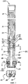
Фиг.1 - изометрический вид первого варианта реализации роторного бурового устройства согласно настоящему раскрытию со смещающими долото поршнями, адаптированными для прямого контакта со стенкой ствола скважины,Figure 1 is an isometric view of a first embodiment of a rotary drilling device according to the present disclosure with biasing bit pistons adapted for direct contact with the wall of the wellbore,
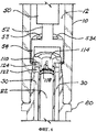
Фиг.2 - вид в продольном разрезе первого варианта реализации роторного бурового устройства, показанного на Фиг.1, в котором дозирующий текучую среду узел содержит вращающуюся верхнюю втулку и зафиксированную нижнюю втулку,FIG. 2 is a longitudinal sectional view of a first embodiment of the rotary drilling device shown in FIG. 1, wherein the fluid metering assembly comprises a rotating upper sleeve and a fixed lower sleeve,
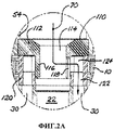
Фиг.2A - увеличенный подробный вид дозирующего текучую среду узла, показанного на Фиг.2,FIG. 2A is an enlarged detailed view of a fluid metering assembly of FIG. 2,
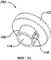
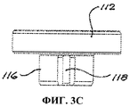
Фиг.3A, 3B и 3C - изометрический вид, вид в разрезе и вид сбоку, соответственно, вращающейся верхней втулки устройства, показанного на Фиг.2,Figa, 3B and 3C is an isometric view, a sectional view and a side view, respectively, of a rotating upper sleeve of the device shown in Fig.2,
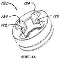
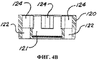
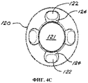
Фиг.4A, 4B и 4C - изометрический вид, вид в разрезе и вид сбоку, соответственно, зафиксированной нижней втулки устройства, показанного на Фиг.2,Figa, 4B and 4C is an isometric view, a sectional view and a side view, respectively, of the fixed lower sleeve of the device shown in Fig.2,
Фиг.5 - вид в поперечном разрезе устройства, показанного на Фиг.2, показывающий дозирующий текучую среду паз во вращающейся верхней втулке, выровненный с впускным отверстием для текучей среды в зафиксированной нижней втулке для обеспечения протекания текучей среды внутрь соответствующего канала для текучей среды в буровом долоте, и показывающий соответствующий поршень выдвинутым,FIG. 5 is a cross-sectional view of the device of FIG. 2, showing a fluid metering groove in a rotating upper sleeve aligned with a fluid inlet in a fixed lower sleeve to allow fluid to flow inside a corresponding fluid channel in a drilling fluid bit, and showing the corresponding piston extended,
Фиг.6 - изометрический местный вид в продольном разрезе средней области устройства, показанного на Фиг.2, показывающий вращающуюся верхнюю втулку, зафиксированную нижнюю втулку с впускными отверстиями для текучей среды и каналы для текучей среды в управляющей секции,6 is a perspective isometric view in longitudinal section of the middle region of the device shown in FIG. 2, showing a rotating upper sleeve, a fixed lower sleeve with fluid inlets and fluid channels in the control section,
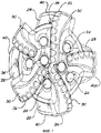
Фиг.7 - вид снизу устройства, показанного на Фиг.2, показывающий буровое долото и корпуса поршней, при этом один смещающий долото поршень выдвинут,Fig.7 is a bottom view of the device shown in Fig.2, showing the drill bit and the piston body, while one biasing bit of the piston is extended,
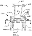
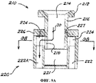
Фиг.8A - вид в разрезе варианта реализации втулочного узла, показанного на Фиг.2-6, с вращающейся верхней втулкой, находящейся в верхней позиции, при которой текучая среда, приводящая поршень в действие, течет внутрь всех каналов для текучей среды,FIG. 8A is a cross-sectional view of an embodiment of the sleeve assembly shown in FIGS. 2-6 with a rotating upper sleeve at an upper position where the fluid driving the piston flows into all fluid channels,
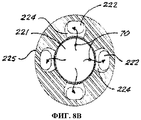
Фиг.8B - вид в поперечном разрезе втулочного узла, показанного на Фиг.8A, иллюстрирующий протекание текучей среды, приводящей поршень в действие, внутрь всех впускных отверстий для текучей среды,FIG. 8B is a cross-sectional view of the sleeve assembly shown in FIG. 8A illustrating the flow of a fluid driving a piston into all fluid inlets;
Фиг.9A - вид в разрезе варианта реализации втулочного узла, показанного на Фиг.8A, с вращающейся верхней втулкой, находящейся в промежуточной позиции, при которой текучая среда, приводящая поршень в действие, течет лишь внутрь одного впускного отверстия для текучей среды,FIG. 9A is a cross-sectional view of an embodiment of the sleeve assembly shown in FIG. 8A with a rotating upper sleeve at an intermediate position where the fluid driving the piston flows only inside one fluid inlet,
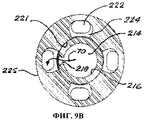
Фиг.9B - вид в поперечном разрезе втулочного узла, показанного на Фиг.9A, иллюстрирующий протекание текучей среды, приводящей поршень в действие, внутрь впускного отверстия для текучей среды, выровненного с пазом во вращающейся верхней втулке,FIG. 9B is a cross-sectional view of the sleeve assembly shown in FIG. 9A illustrating the flow of a fluid driving a piston into a fluid inlet aligned with a groove in a rotating upper sleeve, FIG.
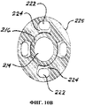
Фиг.10A - вид в разрезе варианта реализации втулочного узла, показанного на Фиг.8A, с вращающейся верхней втулкой, находящейся в нижней позиции, при которой приводящая в действие текучая среда не может течь внутрь всех впускных отверстий для текучей среды,FIG. 10A is a cross-sectional view of an embodiment of the sleeve assembly shown in FIG. 8A with a rotating upper sleeve at a lower position in which the actuating fluid cannot flow into all fluid inlets,
Фиг.10B - вид в поперечном разрезе втулочного узла, показанного на Фиг.10A, иллюстрирующий заблокированное протекание текучей среды во впускные отверстия для текучей среды,Fig. 10B is a cross-sectional view of the sleeve assembly shown in Fig. 10A illustrating a blocked flow of fluid into fluid inlets;
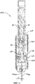
Фиг.11 - вид в продольном разрезе, подобный Фиг.2, показывающий роторное буровое устройство в работе внутри ствола скважины, при этом один поршень радиально выдвинут и прикладывает смещающее долото усилие к одной стороне ствола скважины,11 is a view in longitudinal section, similar to Figure 2, showing the rotary drilling device in operation inside the wellbore, with one piston radially extended and exerts a biasing bit force on one side of the wellbore,
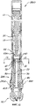
Фиг.12 - вид в продольном разрезе второго варианта реализации роторного бурового устройства, показанного на Фиг.1, с упруго установленным реактивным элементом, относящимся к каждому поршню, и в котором дозирующий текучую среду узел содержит вращающуюся верхнюю пластину и зафиксированную нижнюю пластину,FIG. 12 is a longitudinal sectional view of a second embodiment of the rotary drilling device shown in FIG. 1, with an elastically mounted reactive element associated with each piston, and in which the fluid metering unit comprises a rotating upper plate and a fixed lower plate,
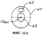
Фиг.12A - вид сверху вращающейся верхней пластины дозирующего текучую среду узла, показанного на Фиг.12,FIG. 12A is a plan view of the rotating top plate of the fluid metering assembly of FIG. 12,
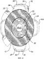
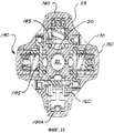
Фиг.12B - вид сверху зафиксированной нижней пластины дозирующего текучую среду узла, показанного на Фиг.12,12B is a plan view of the fixed lower plate of the fluid metering assembly of FIG. 12,
Фиг.13 - вид в поперечном разрезе устройства, показанного на Фиг.12, иллюстрирующий дозирующее текучую среду отверстие во вращающейся верхней пластине, выровненное с впускным отверстием для текучей среды, проходящим сквозь зафиксированную верхнюю пластину внутрь бурового долота, и показывающий соответствующий смещающий долото поршень выдвинутым,FIG. 13 is a cross-sectional view of the device of FIG. 12, illustrating a fluid metering hole in a rotating top plate aligned with a fluid inlet through a fixed top plate inside a drill bit and showing a corresponding biasing bit piston extended ,
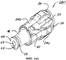
Фиг.14A - изометрический вид управляющей секции устройства, показанного на Фиг.12, с гибким реактивным элементом, установленным на управляющей секции совместно с каждым поршнем,Figa is an isometric view of the control section of the device shown in Fig, with a flexible reactive element mounted on the control section together with each piston,
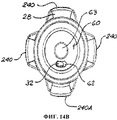
Фиг.14B - вид со стороны верхнего конца устройства, показанного на Фиг.14A, показывающий верхнюю и нижнюю пластины дозирующего текучую среду узла, корпусы поршней и упруго установленные гибкие реактивные элементы,FIG. 14B is a side view of the upper end of the device shown in FIG. 14A showing the upper and lower plates of the fluid metering assembly, piston bodies, and resiliently mounted flexible reactive elements,
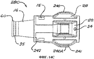
Фиг.14C - вид сбоку устройства, показанного на Фиг.14A, где один поршень приведен в действие и смещает его соответствующий гибкий реактивный элемент,Fig.14C is a side view of the device shown in Fig.14A, where one piston is actuated and biases its corresponding flexible reactive element,
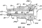
Фиг.14D - вид в продольном разрезе устройства, показанного на Фиг.14A, где один поршень приведен в действие и смещает его соответствующий гибкий реактивный элемент,Fig.14D is a view in longitudinal section of the device shown in Fig.14A, where one piston is actuated and biases its corresponding flexible reactive element,
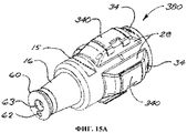
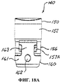
Фиг.15A - изометрический вид управляющей секции устройства, показанного на Фиг.12, с шарнирным реактивным элементом, установленным на управляющей секции совместно с каждым поршнем,Figa is an isometric view of the control section of the device shown in Fig.12, with a hinged reactive element mounted on the control section together with each piston,
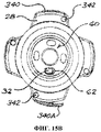
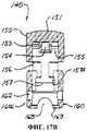
Фиг.15B - вид со стороны верхнего конца устройства, показанного на Фиг.15A, показывающий верхнюю и нижнюю пластины механизма, приводящего поршень в действие, корпусы поршней и шарнирные реактивные элементы,FIG. 15B is a side view of the upper end of the device shown in FIG. 15A showing the upper and lower plates of the piston driving mechanism, piston bodies, and articulated reactive elements,
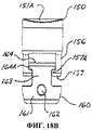
Фиг.15C - вид сбоку устройства, показанного на Фиг.15A, где один поршень приведен в действие и смещает его соответствующий шарнирный реактивный элемент,FIG. 15C is a side view of the device shown in FIG. 15A, where one piston is actuated and biases its corresponding articulated reactive element,
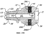
Фиг.15D - вид в продольном разрезе устройства, показанного на Фиг.15A, где один поршень приведен в действие и смещает его соответствующий шарнирный реактивный элемент,Fig.15D is a view in longitudinal section of the device shown in Fig.15A, where one piston is actuated and biases its corresponding articulated reactive element,
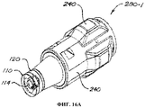
Фиг.16A - изометрический вид варианта реализации управляющей секции устройства, показанного на Фиг.12, с дозирующим текучую среду узлом, включающим втулочный узел, как на Фиг.2-6,FIG. 16A is an isometric view of an embodiment of a control section of the device shown in FIG. 12 with a fluid metering assembly including a sleeve assembly, as in FIGS. 2-6,
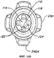
Фиг.16B - вид с верхнего конца устройства, показанного на Фиг.16A, показывающий верхнюю и нижнюю втулки механизма, приводящего поршень в действие, корпусы поршней и упруго установленные гибкие реактивные элементы,Fig.16B is a view from the upper end of the device shown in Fig.16A, showing the upper and lower bushings of the mechanism that drives the piston, the piston bodies and elastically mounted flexible reactive elements,
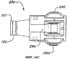
Фиг.16C - вид сбоку устройства, показанного на Фиг.16A, где один поршень приведен в действие и смещает его соответствующий гибкий реактивный элемент,Fig.16C is a side view of the device shown in Fig.16A, where one piston is actuated and biases its corresponding flexible reactive element,
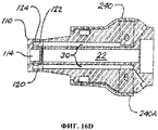
Фиг.16D - вид в продольном разрезе устройства, показанного на Фиг.16A, где один поршень приведен в действие и смещает его соответствующий гибкий реактивный элемент,Fig.16D is a view in longitudinal section of the device shown in Fig.16A, where one piston is actuated and biases its corresponding flexible reactive element,
Фиг.17A - вид в разрезе одного варианта реализации поршневого узла согласно настоящему раскрытию в отведенной позиции,17A is a sectional view of one embodiment of a piston assembly according to the present disclosure in a designated position,
Фиг.17B - вид в разрезе поршневого узла, показанного на Фиг.17A, в выдвинутой позиции (и с не показанной смещающей пружиной для ясности иллюстрации),FIG. 17B is a sectional view of the piston assembly shown in FIG. 17A in an extended position (and with a biasing spring not shown for clarity of illustration),
Фиг.18A - вид сбоку поршневого узла, показанного на Фиг.17A и 17B, в отведенной позиции,Figa is a side view of the piston assembly shown in Fig.17A and 17B, in the designated position,
Фиг.18B - вид сбоку поршневого узла, показанного на Фиг.17A и 17B, в выдвинутой позиции,Figv is a side view of the piston assembly shown in Fig.17A and 17B, in an extended position,
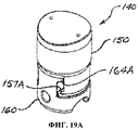
Фиг.19A - изометрический вид поршневого узла, показанного на Фиг.17A-18B, в отведенное позиции,Figa is an isometric view of the piston assembly shown in Fig.17A-18B, in the designated position,
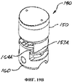
Фиг.19B - изометрический вид поршневого узла, показанного на Фиг.17A-18B, в выдвинутой позиции,Figv is an isometric view of the piston assembly shown in Fig.17A-18B, in the extended position,
Фиг.20A - изометрический вид наружного элемента поршневого узла, показанного на Фиг.17A-19B,Figa - isometric view of the outer element of the piston assembly shown in Fig.17A-19B,
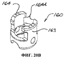
Фиг.20B - изометрический вид внутреннего элемента поршневого узла, показанного на Фиг.17A-19B,Figv is an isometric view of the internal element of the piston assembly shown in Fig.17A-19B,
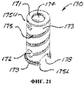
Фиг.21 - изометрический вид смещающей пружины поршневого узла, показанного на Фиг.17A-19B,Fig.21 is an isometric view of the bias spring of the piston assembly shown in Fig.17A-19B,
Фиг.22 - вид в поперечном разрезе управляющей секции бурового устройства, показанного на Фиг.2, включающей поршневые узлы согласно Фиг.17A-21.Fig. 22 is a cross-sectional view of the control section of the drilling device shown in Fig. 2, including the piston assemblies of Figs. 17A-21.
ПОДРОБНОЕ ОПИСАНИЕDETAILED DESCRIPTION
Фиг.1 и 2 иллюстрируют (в изометрическом виде и в продольном разрезе, соответственно) роторное управляемое буровое устройство (или РУС-инструмент) 100 согласно первому варианту реализации. РУС-инструмент 100 содержит цилиндрический корпус 10, который вмещает узел 50 контроля; и буровое долото 20. Кольцевое пространство 12 сформировано вокруг узла 50 контроля внутри корпуса 10, так что буровая текучая среда, текущая внутри корпуса 10, течет вниз через кольцевое пространство 12 к буровому долоту 20. Буровое долото 20 содержит управляющую секцию 80, присоединенную к нижнему концу корпуса 10, и режущую конструкцию 90, присоединенную к нижнему концу управляющей секции 80 так, чтобы иметь возможность вращаться вместе с ней. Управляющая секция 80, предпочтительно, сформирована со средствами для облегчения отделения от корпуса или снабжена этими средствами, такими как пазы 15 для навинчивания и свинчивания долота. Режущая конструкция 90 может быть любого подходящего типа (например, долото с поликристаллическими алмазными вставками или коническое шарошечное долото), и режущая конструкция 90 не формирует часть основных вариантов реализации устройства согласно настоящему раскрытию.Figures 1 and 2 illustrate (in isometric view and in longitudinal section, respectively) of a rotary guided drilling device (or RUS tool) 100 according to the first embodiment. The
Управляющая секция 80 имеет по меньшей мере один канал 30 для текучей среды, проходящий вниз от верхнего конца управляющей секции 80. Как видно на Фиг.2, управляющая секция 80 также имеет центральный осевой канал 22 для перемещения текучей среды к режущей конструкции 90, где буровая текучая среда может выходить под давлением через сопла 24 (для повышения эффективности режущей конструкции 90, когда она вбуривается внутрь материалов подземных пород). Каждый канал 30 для текучей среды ведет к радиально внутреннему концу соответствующего поршня 40, выполненного с возможностью выдвижения радиально наружу из управляющей секции 80 под действием давления приводящей в действие текучей среды, текущей под давлением через канал 30 для текучей среды. Обычно каждый канал 30 для текучей среды проходит на другую сторону его соответствующего поршня 40 к концевому соплу 34 долота, которое обеспечивает возможность слива текучей среды и стравливания давления текучей среды.The
Управляющая секция 80 определяет и включает корпусы 28 поршней, отходящие наружу от управляющей секции 80 (основное тело которой обычно имеет диаметр, равный или близкий к диаметру корпуса 10). Радиальный ход каждого поршня 40, предпочтительно, ограничен любыми подходящими средствами (представленными в качестве примера на Фиг.12 в форме поперечного стержня 41, проходящего через щелевое отверстие 43 в поршне 40 и закрепленного внутри корпуса 28 поршня на каждой стороне поршня 40). Этот конкретный признак приведен лишь в качестве примера, и специалисты в данной области должны понимать, что другие средства для ограничения хода поршня могут быть с легкостью разработаны без выхода за рамки объема настоящего раскрытия. Поршни 40 также, предпочтительно, снабжены подходящими смещающими средствами (такими как, в качестве неограничивающего примера, смещающие пружины), смещающими поршни 40 в отведенную позицию внутри их соответствующих корпусов 28 поршней.The
В типовом случае текучая среда, приводящая поршень в действие, представляет собой часть буровой текучей среды, отделившуюся от текучей среды, текущей через осевой канал 22 к режущей конструкции 90. Однако текучая среда, приводящая поршень в действие, может в других вариантах реализации представлять собой текучую среду, отличную и/или поступающую из другого источника по отношению буровой текучей среде, текущей к режущей конструкции 90.Typically, the fluid driving the piston is a portion of the drilling fluid that is separated from the fluid flowing through the
РУС-инструмент 100 включает дозирующий текучую среду узел, который в варианте реализации, показанном на Фиг.2, содержит верхнюю втулку 110, которая выполнена с возможностью вращения посредством узла 50 контроля внутри и относительно нижней втулки 120, которая, в свою очередь, является зафиксированной на верхнем конце управляющей секции 80 или выполненной за одно целое с верхним концом управляющей секции 80. Как лучше всего видно на Фиг.2A, 3A, 3B и 3C, выполненная с возможностью вращения верхняя втулка 110 имеет отверстие 114, проходящее через цилиндрическую секцию 116, проходящую вниз ниже кольцевого верхнего выступа 112. Цилиндрическая секция 116 имеет дозирующее текучую среду отверстие, показанное в форме вертикального паза 118. Как видно на Фиг.2A, 4A, 4B и 4C, зафиксированная нижняя втулка 120 имеет отверстие 121 и впускные отверстия 122 для текучей среды, геометрически расположенные так, чтобы соответствовать каналам 30 для текучей среды в управляющей секции 80. В изображенных вариантах реализации впускные отверстия 122 для текучей среды имеют круговое расположение, центром которого является продольная осевая линия CLRSS РУС-инструмента 100.The
Углубления 124 сформированы внутри верхней области нижней втулки 120 для обеспечения сообщения текучей средой между каждым впускным отверстием 122 для текучей среды и отверстием 121. Соответственно, и как лучше всего видно на Фиг.2A и 6, когда цилиндрическая секция 116 верхней втулки 110 расположена внутри отверстия 121 нижней втулки 120 с дозирующим текучую среду пазом 118, выровненным с данным углублением 124 в нижней втулке 120, отверстие 114 верхней втулки 110 сообщается через текучую среду с соответствующим каналом 30 для текучей среды в управляющей секции 80 через паз 118, углубление 124 и впускное отверстие 122 для текучей среды. Как можно видеть на Фиг.5, результирующий поток приводящей в действие текучей среды, находящейся под давлением, внутри соответствующего канала 30 для текучей среды вызывает приведение в действие и выдвижение радиально наружу соответствующего поршня (показанного на Фиг.5 позицией 40A, используемой для обозначения приведенного в действие поршня).
Узел и работа дозирующего текучую среду узла, описанные выше, могут быть дополнительно уяснены со ссылкой на Фиг.6. Узел 50 контроля снабжен средствами взаимодействия с дозирующим узлом для вращения верхней втулки 110, и они могут иметь любую функционально эффективную форму. В качестве неограничивающего примера, средства взаимодействия с дозирующим узлом показаны на Фиг.2, 2A и 6 как содержащие вал 52, оперативно присоединенный на его верхнем конце к узлу 50 контроля и присоединенный на его нижнем конце к цилиндрическому держателю 54, имеющему верхнюю концевую пластину 53 по меньшей мере с одним отверстием 53A для текучей среды. Цилиндрический держатель 54 концентрично присоединен на его нижнем конце 54L к выступу 112 верхней втулки 110, так что верхняя втулка 110 вращается относительно нижней втулки 120, когда вал 52 вращается узлом 50 контроля. Текучая среда 70, текущая вниз внутри кольцевого пространства 12, окружающего узел 50 контроля внутри корпуса 10, течет через отверстия 53A для текучей среды в верхней концевой пластине 53 держателя 54, внутрь цилиндрической полости 55 внутри держателя 54, а затем внутрь отверстия 114 верхней втулки 110. Часть текучей среды 70 отделяется через паз 118 в цилиндрической секции 116 верхней втулки 110 внутрь впускного отверстия 120 для текучей среды, выровненного в это время с пазом 118, а затем - внутрь соответствующего канала 30 для текучей среды для приведения в действие соответствующего поршня 40. Остальная часть текучей среды 70 течет внутрь основного осевого канала 22 в управляющей секции 80 для ее доставки к режущей конструкции 90.The assembly and operation of the fluid metering assembly described above can be further clarified with reference to FIG. 6. The
Фиг.7 - вид снизу бурового долота 20, показывающий режущую конструкцию 90 с режущими элементами или зубьями 92, соплами 24 долота, поршнями 40 и корпусами 28 поршней. На Фиг.13 один поршень, обозначенный позицией 40A, показан в его приведенной в действие позиции выдвинутым радиально наружу от его корпуса 28 поршня.7 is a bottom view of the
Фиг.8A иллюстрирует вариант реализации втулочного узла, показанного на Фиг.2 и 6 и соответствующих деталировочных чертежах. Верхняя втулка 210 на Фиг.8A в целом подобна верхней втулке 110, показанной на Фиг.3A-3C, тем, что выступ 212 и отверстие 214 подобны выступу 112 и отверстию 114 в верхней втулке 110, но отличается от втулки 110 тем, что что она имеет цилиндрическую секцию 216, более длинную, чем цилиндрическая секция 116 в верхней втулке 110. Цилиндрическая секция 216 имеет дозирующий текучую среду паз 218, подобный дозирующему текучую среду пазу 118 в цилиндрической секции 116, расположенный в нижней области цилиндрической секции 216. Нижняя втулка 220, показанная на Фиг.8A, в целом подобна нижней втулке 120, показанной на Фиг.4A-4C, тем, что она имеет впускные отверстия 222 для текучей среды ниже соответствующих углублений 224 (подобные впускным отверстиям 122 для текучей среды и углублениям 124 в нижней втулке 120), сформированные в нижнем теле 225, имеющем отверстие 221, аналогичное отверстию 121 в нижней втулке 120, но отличается от нижней втулки 120 тем, что дополнительно имеет покрывающую пластину 226, проходящую через верх нижнего тела 225 и имеющую центральное отверстие для приема цилиндрической секции 216 верхней втулки 210.FIG. 8A illustrates an embodiment of the sleeve assembly shown in FIGS. 2 and 6 and corresponding detail drawings. The
Как можно понять из Фиг.8A и 8B, когда верхняя втулка 210 находится в верхней позиции относительно нижней втулки 220, при этом поднятая цилиндрическая секция 216 по меньшей мере частично открывает углубления 224 в нижней втулке 220, части текучей среды 70, текущей внутри отверстия 214 в верхней втулке 210, и отверстия 221 в нижней втулке 220, отделяются непосредственно внутрь всех углублений 224 и впускных отверстий 222 для текучей среды для приведения в действие всех поршней 40. В этом рабочем режиме приведенные в действие поршни служат для центрирования и стабилизации бурового долота 20 при бурении неотклоняемой секции ствола скважины. Это может быть особенно благоприятным и выгодным при бурении прямой, но не вертикальной секции ствола скважины и/или когда необходимо довести до максимума суммарную площадь потока (СПП) на долоте (СПП определена как суммарная площадь всех форсунок или сопел, через которые текучая среда может вытекать из долота). СПП является наибольшей, когда верхняя втулка 210 находится в ее самой верхней позиции, при которой текучая среда может течь внутрь всех каналов 30 для текучей среды. Это обусловлено тем, что текучая среда при этом способна вытекать из всех концевых сопел 34 долота, соединенных с каналами 30 для текучей среды, в дополнение к вытеканию из всех сопел 24 долота в режущей конструкции 90. И, наоборот, СПП является наименьшей, когда верхняя втулка 210 находится в ее самой нижней позиции (как показано на Фиг.10A и 10B), при которой поток текучей среды внутрь всех каналов 30 для текучей среды заблокирован, и текучая среда может выходить из инструмента лишь через сопла 24 долота.As can be understood from FIGS. 8A and 8B, when the
Стабилизация бурового долота посредством выдвижения всех поршней может также быть желательной во время «прямого» бурения для уменьшения «вибраций долота», которые могут быть результатом низкого качества ствола скважины при бурении сквозь мягкие породы.Stabilization of the drill bit by extending all the pistons may also be desirable during “direct” drilling to reduce “bit vibrations” that may result from poor quality of the wellbore when drilling through soft rock.
Фиг.9A и 9B иллюстрируют ситуацию, когда верхняя втулка 210 находится в промежуточной позиции относительно нижней втулки 220, при этом цилиндрическая секция 216 проходит ниже покрывающей пластины 226 для обеспечения возможности протекания текучей среды из отверстия 214 через дозирующий текучую среду паз 218. В этом рабочем режиме текучая среда 70 отделяется внутрь углубления 224, выровненного с пазом 218, а затем течет внутрь соответствующего впускного отверстия 222 для текучей среды для приведения в действие соответствующего поршня 40; т.е. происходит по существу то же самое, что и в втулочном узле, показанном на Фиг.2A.9A and 9B illustrate a situation where the
Фиг.10A и 10B иллюстрируют ситуацию, когда верхняя втулка 210 находится в нижней позиции относительно нижней втулки 220, при этом паз 218 расположен ниже углублений 224, так что текучая среда не может входить в какое-либо из углублений 224 и впускных отверстий 222 для текучей среды. В этом рабочем режиме вся текучая среда 70 течет непосредственно к режущей конструкции 90 без отделения. Это может быть желательным для прямого бурения через сравнительно стабильные подземные породы при меньшей СПП на долоте.10A and 10B illustrate a situation where the
Для оперирования дозирующим текучую среду узлом, включающим верхнюю и нижнюю втулки 210 и 220, как показано на Фиг.8A-10B, узел 50 контроля включает средства для подъема и опускания верхней втулки 210 или снабжен средствами для подъема и опускания верхней втулки 210 в дополнение к вращению верхней втулки 210. Специалисты в данной области должны понимать, что различные средства для осевого перемещения верхней втулки 210 относительно нижней втулки 220 могут быть разработаны в соответствии с известными технологиями, и настоящее раскрытие не ограничено использованием каких-либо конкретных таких средств.For operating a fluid metering assembly including upper and
Фиг.11 иллюстрирует РУС-инструмент 100, показанный на Фиг.2, во время работы внутри ствола WB скважины. На этом виде часть 70A текучей среды 70 из кольцевого пространства 12 РУС-инструмента 100 отделилась в «активный» канал 30A для текучей среды в управляющей секции 80 через дозирующий текучую среду паз 118 во вращающейся верхней втулке 110 дозирующего текучую среду узла. Поток текучей среды, находящейся под давлением, внутри канала 30A для текучей среды приводит в действие соответствующий поршень 40A, вынуждая приведенный в действие поршень 40A выдвинуться радиально наружу из управляющей секции 80 в реактивный контакт со стенкой ствола WB скважины в контактной области WX, тем самым приложив поперечное усилие к управляющей секции 80, сместив режущую конструкцию 90 в направлении от контактной области WX на расстояние D смещения, которое представляет собой поперечный сдвиг смещенной осевой линии CLRSS РУС-инструмента 100 относительно осевой линии CLWB ствола WB скважины. Контактная область WX для данной фиксированной ориентации верхней втулки 110 и ее дозирующего текучую среду паза 118 относительно ствола WB скважины не является конкретной фиксированной точкой или конкретной фиксированной областью на стенке ствола скважины, а, напротив, перемещается по мере продвижения процесса бурения глубже внутрь грунта. При этом для рабочих режимов, обеспечивающих приведение в действие лишь одного поршня 40 в данный момент времени, контактная область WX всегда соответствует угловому положению дозирующего текучую среду паза 118.11 illustrates the
Когда инструмент 100 продолжает вращение, поток приводящей в действие текучей среды 70A внутрь активного канала 30A для текучей среды блокируется, в результате чего сбрасывается гидравлическое усилие, приводящее в действие поршень 40A, который затем отводится внутрь тела управляющей секции 80. Дальнейшее вращение инструмента 100 вынуждает приводящую в действие текучую среду течь внутрь следующего канала 30 для текучей среды в управляющей секции 80, тем самым приводя в действие и выдвигая следующий поршень 40 последовательно и прикладывая еще одно поперечное усилие в контактной области WX ствола WB скважины.When the
Соответственно, для каждого оборота инструмента 100 поперечное усилие, отклоняющее долото, прикладывается к стволу WB скважины в контактной области WX такое же количество раз, что и количество каналов 30 для текучей среды в управляющей секции 80, тем самым поддерживая эффективно постоянное расстояние D смещения режущей конструкции 90 в постоянном поперечном направлении относительно ствола WB скважины. В результате этого смещения угловая ориентация ствола WB скважины постепенно изменяется, создавая искривленную секцию в стволе WB скважины.Accordingly, for each revolution of the
Когда желаемая степень кривизны или отклонения ствола скважины была достигнута, и требуется бурить неотклоненную секцию ствола скважины, работу узла 50 контроля регулируют для вращения верхней втулки 110 так, чтобы дозирующий текучую среду паз 118 находился в нейтральной позиции между парой соседних углублений 124 в нижней втулке 120, так что текучая среда 70 не может отделяться внутрь какого-либо из впускных отверстий 122 для текучей среды в нижней втулке 120. Узел 50 контроля (или средства взаимодействия с дозирующим узлом) затем либо выводят из взаимодействия с верхней втулкой 110, оставляя верхнюю втулку 110 свободной для вращения с нижней втулкой 120 и управляющей секцией 80, или - в другом варианте реализации - приводят верхнюю втулку 110 во вращение с такой же скоростью, что и инструмент 100, тем самым в любом случае поддерживая паз 118 в нейтральной позиции относительно нижней втулки 120, так что текучая среда не может течь к какому-либо из поршней 40. Буровые операции могут затем быть продолжены без какого-либо поперечного усилия, действующего для смещения режущей конструкции 90.When the desired degree of curvature or deviation of the wellbore has been achieved and a non-deviated section of the wellbore is required to be drilled, the operation of the
В вариантах реализации, в которых дозирующий текучую среду узел включает выполненную с возможностью осевого перемещения верхнюю втулку 210 и нижнюю втулку 220, как показано на Фиг.8A-10B, переход к неотклоняемым буровым операциям выполняют путем перемещения верхней втулки 210 (посредством узла 50 контроля) в ее верхнюю или нижнюю позицию относительно нижней втулки 220, как может быть необходимым или подходящим с операционной точки зрения. Поток текучей среды к каналам 30 для текучей среды тем самым предотвращается независимо от того, продолжает ли верхняя втулка 210 вращаться относительно нижней втулки 220.In embodiments in which the fluid metering assembly includes an axially displaceable
Фиг.12 иллюстрирует РУС-инструмент 200 согласно еще одному варианту реализации, в котором дозирующий текучую среду узел содержит вращающуюся верхнюю пластину 60 и нижнюю пластину 35, зафиксированную на верхнем конце модифицированной управляющей секции 280 или выполненную за одно целое с верхним концом модифицированной управляющей секции 280. Нижняя пластина 35 имеет по меньшей мере одно впускное отверстие 32 для текучей среды, аналогичное впускным отверстиям 122 для текучей среды в нижней втулке 120, показанной на Фиг.2 и 6 (и в других частях настоящего документа). В изображенном варианте реализации и как показано на Фиг.12B, впускные отверстия 32 для текучей среды имеют круговое расположение, центром которого является осевая линия CLRSS РУС-инструмента 200. Верхняя пластина 60 выполнена с возможностью вращения относительно корпуса 10 вокруг оси вращения, совпадающей с осевой линией CLRSS. Как показано на Фиг.12A, верхняя пластина 60 имеет дозирующее текучую среду отверстие 62, смещенное от осевой линии CLRSS на радиус, соответствующий радиусу кругового расположения впускных отверстий 32 для текучей среды, сформированных в зафиксированной нижней пластине 35. Верхняя пластина 60 также имеет центральное отверстие 63 для обеспечения возможности протекания текучей среды вниз внутрь осевого канала 22 управляющей секции 80, и нижняя пластина 35 имеет центральное отверстие 33 для этой же цели.12 illustrates a
Дозирующий текучую среду узел показанный на Фиг.12, 12A и 12B, функционирует по существу таким же способом, что был описан для вариантов реализации РУС-инструмента, имеющих дозирующий текучую среду узел, включающий верхнюю втулку 110 (или 210) и нижнюю втулку 120 (или 220). Верхняя пластина 60 вращается узлом 50 контроля (например, посредством держателя 54, как описано выше), с тем чтобы удерживать дозирующее текучую среду отверстие 62 в фиксированной ориентации относительно ствола WB скважины независимо от вращения корпуса 10 и управляющей секции 80. Когда корпус 10 и управляющая секция 80 вращаются относительно ствола WB скважины, дозирующее текучую среду отверстие 62 в верхней пластине 60 входит в выравнивание с каждым из впускных отверстий 32 для текучей среды в нижней пластине 35 последовательно, тем самым позволяя части текучей среды, текущей из кольцевого пространства 12 через отверстия 53A в верхней концевой пластине 53 держателя 54, отделяться внутрь каждого канала 30 для текучей среды последовательно и вынуждать соответствующие поршни 40 радиально выдвигаться последовательно, тем самым вызывая отклонение в ориентации ствола WB скважины, как описано выше.The fluid metering assembly shown in FIGS. 12, 12A and 12B operates in substantially the same manner as described for embodiments of a RUS tool having a fluid metering assembly including an upper sleeve 110 (or 210) and a lower sleeve 120 ( or 220). The
Фиг.13 - вид в поперечном разрезе корпуса 10 непосредственно над верхней пластиной 60, показывающий смещенное отверстие 62 в верхней пластине 60 и - пунктирными линиями - впускные отверстия 32 для текучей среды (всего четыре в изображенном варианте реализации) в зафиксированной нижней пластине 35, расположенной ниже верхней пластины 60. Кроме того, Фиг.13 иллюстрирует поршни 40 и их соответствующие корпуса 28 поршней (всего четыре, что соответствует количеству впускных отверстий 32 для текучей среды) и расположенную ниже них режущую конструкцию 90 с зубьями 92 бурового долота. Фиг.13 иллюстрирует выравнивание дозирующего текучую среду отверстия 62 верхней пластины 60 с одним из впускных отверстий 32 для текучей среды в нижней пластине 35, обеспечивающее в результате выдвижение радиально наружу соответствующего приведенного в действие поршня 40A.13 is a cross-sectional view of the
Для перевода РУС-инструмента 200 на неотклоняемые буровые операции узел 50 контроля приводят в действие для вращения верхней пластины 60 в нейтральную позицию относительно нижней пластины, так что дозирующее текучую среду отверстие 62 не находится в выравнивании с каким-либо из впускных отверстий 32 для текучей среды в нижней пластине 35, и верхнюю пластину 60 затем вращают с такой же скоростью, что и управляющую секцию 80 для удержания дозирующего текучую среду отверстия 62 в нейтральной позиции относительно нижней пластины 35.To translate the
В еще одном варианте реализации устройства (не показан) верхнюю пластину 60 могут выборочно перемещать в осевом направлении вверх от нижней пластины 35, тем самым обеспечивая возможность протекания текучей среды внутрь всех каналов 30 для текучей среды и вызывая выдвижение наружу всех поршней 40. Это приводит к тому, что одинаковые поперечные усилия приложены вокруг периметра управляющей секции 80 и эффективно вынуждают режущую конструкцию 90 бурить прямо, без отклонения, в то же время также стабилизируя режущую конструкцию 90 внутри ствола WB скважины подобно случаю для описанных выше вариантов реализации, включающих верхнюю и нижнюю втулки 210 и 220, когда верхняя втулка 210 находится в ее верхней позиции относительно нижней втулки 220. Система 50 контроля может быть деактивирована или переведена в режим пониженного энергопотребления, когда верхняя пластина 60 и нижняя пластина 35 не находятся в контакте, чем увеличивается срок службы батареи и уменьшается износ компонентов системы контроля.In yet another embodiment of the device (not shown), the
В одном варианте реализации узел 50 контроля содержит управляемый электроникой объемный двигатель (ОД), который вращает верхнюю пластину 60 (или верхнюю втулку 110 или 210), но узел 50 контроля не ограничен этим или каким-либо другим конкретным типом механизма.In one embodiment, the
Управляемые роторные буровые системы согласно настоящему раскрытию могут быть с легкостью адаптированы для облегчения замены интенсивно циклично используемых поршней во время замен долота. Эта возможность замены поршней независимо от системы контроля - в конструкции, которая обеспечивает соединения с возможностью замены на месте эксплуатации, - делает систему более компактной, простой для обслуживания, более универсальной и более надежной, чем стандартные управляемые системы. РУС-инструменты согласно настоящему раскрытию также обеспечивают возможность использования разных размеров и типов буровых долот и/или поршней совместно с одной и той же системой контроля без необходимости замены чего-либо еще, кроме управляющей системы и/или режущей конструкции. Это означает, например, что система может быть использована для бурения 12-1/4'' (311 мм) ствола скважины, а затем быть использована для бурения 8-3/4'' (222 мм) ствола скважины без изменения размера корпуса системы контроля, тем самым экономя время и требуя меньше оборудования.The controllable rotary drilling systems of the present disclosure can be easily adapted to facilitate the replacement of intensively used pistons during bit changes. This ability to replace pistons regardless of the control system — in a design that provides field-replaceable connections — makes the system more compact, easy to maintain, more versatile, and more reliable than standard controlled systems. RUS tools according to the present disclosure also provide the ability to use different sizes and types of drill bits and / or pistons in conjunction with the same control system without the need to replace anything other than a control system and / or cutting structure. This means, for example, that the system can be used to drill 12-1 / 4 '' (311 mm) of the wellbore, and then be used to drill 8-3 / 4 '' (222 mm) of the wellbore without changing the size of the system’s body control, thereby saving time and requiring less equipment.
Система может также быть адаптирована для обеспечения возможности использования бурового долота отдельно от системы контроля. Дополнительно узел контроля может иметь модульную конструкцию для контроля не только буровых долот, но также других буровых инструментов, которые могут с выгодой использовать вращающуюся верхнюю пластину (или втулку) инструмента для выполнения полезных работ.The system can also be adapted to allow the use of a drill bit separately from the control system. Additionally, the control unit may have a modular design for monitoring not only drill bits, but also other drilling tools that can advantageously use the rotating upper plate (or sleeve) of the tool to perform useful work.
Фиг.14A, 14B, 14C и 14D иллюстрируют управляющую секцию 280 РУС-инструмента согласно варианту реализации, показанному на Фиг.12. Управляющая секция 280 по существу подобна управляющей секции 80, описанной со ссылкой на Фиг.2, и одинаковые позиции использованы для компонентов, общих для обоих вариантов реализации. Управляющая секция 280 показана - в качестве неограничивающего примера - с верхним концом 16 с наружной резьбой для резьбового присоединения к нижнему концу корпуса 10 и с нижним концом 17 с внутренней резьбой для резьбового присоединения к верхнему концу режущей конструкции 90. Управляющая секция 280 отличается от управляющей секции 80, показанной на Фиг.2, наличием гибких реактивных накладок 240, каждая из которых имеет верхний конец, упруго установленный на основное тело управляющей секции, и свободный нижний конец 241, который проходит поверх соответствующего корпуса 28 поршня. В изображенном варианте реализации упругая установка гибких реактивных накладок 240 на тело управляющей секции 280 осуществлена за счет того, что верхние концы реактивных накладок 240 сформированы за одно целое с охватывающим ободом 242, расположенным внутри кольцевой канавки 243, проходящей вокруг периферии управляющей секции 280 в месте ниже конца 16 с наружной резьбой. Однако это лишь пример. Специалисты в данной области должны понимать, что другие способы упругой установки верхних концов реактивных накладок 240 на управляющей секции 280 могут быть с легкостью разработаны, и настоящее раскрытие не ограничено использованием каких-либо конкретных средств или способов установки реактивных накладок 240.FIGS. 14A, 14B, 14C, and 14D illustrate a
Как лучше всего видно на верхней части Фиг.14D, когда данный поршень 40 находится в его отведенной позиции, свободный нижний конец 241 его соответствующей гибкой реактивной накладки 240, предпочтительно, лежит на одном уровне или почти на одном уровне с наружной поверхностью соответствующего корпуса 28 поршня. Однако когда поршень приведен в действие (как изображено приведенным в действие поршнем 40A в нижней части Фиг.14D), он смещает свободный нижний конец 241 соответствующей реактивной накладки (обозначенной позицией 240A на Фиг.14D) радиально наружу. Смещенная гибкая реактивная накладка 240A тем самым отклоняется и прижимается к стенке ствола скважины, в результате чего управляющая секция 280 и режущая конструкция 90 отклоняются в радиально противоположном направлении. Когда приведенный в действие поршень 40A отводится внутрь его корпуса 28 поршня, свободный конец реактивной накладки 240A упруго возвращается в его ненапряженные состояние и позицию.As best seen in the upper part of Fig. 14D, when the
Фиг.15A, 15B, 15C и 15D иллюстрируют управляющую секцию 380 РУС-инструмента согласно еще одному варианту реализации. Управляющая секция 380 по существу подобна управляющей секции 80, описанной со ссылкой на Фиг.2, и одинаковые позиции использованы для компонентов, общих для обоих вариантов реализации. Управляющая секция 380 отличается от управляющей секции 80 наличием шарнирных реактивных накладок 340, каждая из которых проходит поверх соответствующего корпуса 28 поршня, к которому реактивная накладка 340 присоединена по меньшей мере одним шарниром 342, с тем чтобы иметь возможность поворота вокруг оси шарнира, по существу параллельной продольной оси управляющей секции 380. Шарниры 342, предпочтительно, расположены на ведущих краях шарнирных реактивных накладок 340 (термин «ведущий край» относится к направлению вращения инструмента).Figa, 15B, 15C and 15D illustrate the
Как лучше всего видно на верхней части Фиг.15D, когда данный поршень 40 находится в его отведенной позиции, соответствующая шарнирная реактивная накладка 340, предпочтительно, лежит на одном уровне или почти на одном уровне с поверхностью соответствующего корпуса 28 поршня. Однако, когда поршень приведен в действие (как изображено приведенным в действие поршнем 40A в нижней части Фиг.15D), он отклоняет наружу его соответствующую шарнирную реактивную накладку 340A, вынуждая накладку 340A повернуться вокруг ее шарнира(ов), сместиться наружу и прижаться к стенке ствола скважины, как видно на Фиг.15C и 15D. В результате управляющая секция 380 и режущая конструкция 90 отклоняются в радиально противоположном направлении. Когда приведенный в действие поршень 40A отводится внутрь его корпуса 28 поршня, смещенная шарнирная реактивная накладка 340A может быть возвращена в ее исходную позицию при помощи, в зависимости от ситуации, подходящих смещающих средств.As best seen in the upper part of FIG. 15D, when a given
Фиг.16A, 16B, 16C и 16D иллюстрируют вариант 280-1 управляющей секции 280, показанной на Фиг.14A, 14B, 14C и 14D, отличающийся лишь тем, что дозирующий текучую среду узел в управляющей секции 280-1 включает верхнюю и нижнюю втулки 110 и 120, как на Фиг.3A-3C и 4A-4C, а не верхнюю и нижнюю пластины 60 и 35, как в управляющей секции 280. Компоненты и признаки, не имеющие позиций на Фиг.16A, 16B, 16C и 16D, соответствуют таким же компонентам и признакам, показанным на Фиг.14A, 14B, 14C и 14D. Специалисты в данной области должны также понимать, что управляющая секция 380, показанная на Фиг.15A, 15B, 15C и 15D может быть так же модифицирована.Figa, 16B, 16C and 16D illustrate a variant 280-1 of the
РУС-инструменты согласно настоящему раскрытию могут использовать поршни любого функционально подходящего типа и любой функционально подходящей конструкции, и раскрытие не ограничено использованием какого-либо конкретного типа поршня, описанного или изображенного в настоящем документе. Фиг.12, 14D, 15D и 16D, например, показывают цельные, или состоящие из одной части, поршни 40. Фиг.17A-21 иллюстрируют вариант реализации поршневого узла 140, содержащего наружный (или верхний) элемент 150, внутренний (или нижний) элемент 160 и, в предпочтительных вариантах реализации, смещающую пружину 170. В настоящем описании поршневого узла 140 и его составляющих элементов прилагательные «внутренний» и «наружный» использованы по отношению к осевой линии управляющей секции 80, совместно с которой поршень 140 установлен; т.е. внутренний элемент 160 расположен радиально внутри относительно наружного элемента 150, в то время как наружный элемент 150 выполнен с возможностью выдвижения радиально наружу из управляющей секции 80 (и от внутреннего элемента 160). Однако для удобства в описании этих компонентов прилагательные «верхний» и «нижний» могут быть использованы взаимозаменяемо с прилагательными «наружный» и «внутренний», соответственно, в зависимости от графического представления этих элементов на Фиг.17A-21.RUS tools according to the present disclosure may use pistons of any functionally suitable type and any functionally suitable design, and the disclosure is not limited to the use of any particular type of piston described or depicted herein. 12, 14D, 15D, and 16D, for example, show
Как показано в подробностях на Фиг.17A и 17B, наружный элемент 150 поршневого узла 140 имеет цилиндрическую боковую стенку 152 с верхним концом 152U, который закрыт крышечным элементом 151, и открытым нижним концом 152L. Верхняя (или наружная) поверхность 151A крышечного элемента 151 может иметь контур, как на Фиг.17A, 17B или как на Фиг.18A, 18B, чтобы соответствовать эффективному диаметру режущей конструкции 90, установленной на управляющей секции 80, в вариантах реализации, предназначенных для прямого контакта поршня со стенкой ствола скважины без участия реактивных элементов. Вариант реализации наружного элемента 150, показанный на Фиг.17A и 17B, адаптирован для приема верхнего конца смещающей пружины 170 (способом, описанным ниже в настоящем документе) и для этой цели сформирован с цилиндрическим выступом 153, проходящим соосно вниз от крышечного элемента 151 и имеющим открытую снизу и снабженную внутренней резьбой полость 154. Открытое снизу кольцевое пространство 155, таким образом, сформировано между выступом 153 и боковой стенкой 152 наружного элемента 150.As shown in detail in FIGS. 17A and 17B, the
Вниз от цилиндрической боковой стенки 152 проходит пара находящихся на расстоянии искривленных и диаметрально противоположных выступов 156 боковой стенки, каждый из которых имеет нижнюю часть 157, сформированную с проходящим по окружности зацепом или стопорным элементом 157A на каждом окружном конце нижней части 157. Каждый выступ 156 боковой стенки может, таким образом, быть описан как имеющий в целом перевернутую T-образную форму с парой диаметрально противоположных отверстий 156A боковой стенки, сформированных между этими двумя выступами 156 боковой стенки.A pair of spaced apart and diametrically opposite
Внутренний элемент 160 поршневого узла 140 имеет цилиндрическую боковую стенку 161, которая имеет верхний конец 160U и нижний конец 160L и охватывает цилиндрическую полость 165, которая открыта на каждом конце. Пара диаметрально противоположных отверстий 162 для удерживающего пальца сформирована сквозь боковую стенку 161 для приема удерживающего пальца 145 для закрепления внутреннего элемента 160 относительно управляющей секции 80 и внутри управляющей секции 80, так что позиция внутреннего элемента 160 относительно управляющей секции 80 радиально зафиксирована. Пара диаметрально противоположных отверстий 168 для текучей среды (полукруглых или полуовальных в изображенном варианте реализации) сформирована внутри боковой стенки 161 внутреннего элемента 160 так, что эти отверстия прерывают нижний конец 160L внутреннего элемента 160, проходят под прямыми углами к отверстиям 162 для удерживающего пальца и в целом выровнены с соответствующими каналами 30 для текучей среды, когда поршневой узел 140 установлен в управляющую секцию 80, для обеспечения возможности прохождения буровой текучей среды вниз дальше внутреннего элемента 160 внутрь соответствующего сопла 34 долота в управляющей секции 80. Как лучше всего видно на Фиг.17B, и как будет описано ниже в настоящем документе, кольцевая канавка 169 сформирована вокруг полости 165 на нижнем конце 160L внутреннего элемента 160. В изображенном варианте реализации кольцевая канавка 169 является прерывистой и прерывается отверстиями 168 для текучей среды.The
Вверх от цилиндрической боковой стенки 161 проходит пара находящихся на расстоянии, искривленных и диаметрально противоположных выступов 163 боковой стенки, каждый из которых имеет верхнюю часть 164, сформированную так, что она определяет проходящий по окружности зацеп или стопорный элемент 164A на каждом окружном конце верхней части 164. Каждый выступ 163 боковой стенки может, таким образом, быть описан как имеющий в целом T-образную форму с парой диаметрально противоположных отверстий 163A боковой стенки, сформированных между двумя выступами 163 боковой стенки. В сочетании зацепы 157A и 164A, таким образом, служат в качестве ограничивающих ход средств, определяющих максимальный радиальный ход наружного элемента 150 поршневого узла 140.A pair of spaced, curved and diametrically
Как можно лучше всего понять из Фиг.18A, 18B, 19A и 19B, наружный элемент 150 и внутренний элемент 160 могут быть собраны путем поперечного введения верхних частей выступов 163 боковой стенки внутреннего элемента внутрь отверстий 156A боковой стенки наружного элемента 150 так, чтобы наружный элемент 150 и внутренний элемент 160 были в осевом выравнивании. Наружный элемент 150 может перемещаться в осевом направлении относительно внутреннего элемента 160 (т.е. радиально относительно управляющей секции 80), при этом наружное осевое перемещение наружного элемента 150 ограничено примыканием зацепов 157A, расположенных на наружном элементе 150, к зацепам 164A, расположенным на внутреннем элементе 160, как видно на Фиг.17B, 18B и 19B.As best understood from FIGS. 18A, 18B, 19A and 19B, the
Смещающая пружина 170, показанная в изометрическом виде на Фиг.21, содержит цилиндрическую боковую стенку 173, которая имеет верхний конец 173U и нижний конец 173L и определяет цилиндрическую внутреннюю камеру 174. Верхний конец 173U боковой стенки 173 сформирован с или снабжен проходящим внутрь кольцевым выступом 171, а нижний конец 173L боковой стенки 173 сформирован с или снабжен проходящим наружу кольцевым выступом 179. Спиральный паз 175 сформирован сквозь боковую стенку 173, так что боковая стенка 173 имеет форму спиральный пружины, при этом спиральный паз 175 имеет верхний конец вблизи кольцевого выступа 171 и нижний конец вблизи кольцевого выступа 179. Пара диаметрально противоположных отверстий 172 для удерживающего пальца сформирована сквозь боковую стенку 173 для приема удерживающего пальца 145, когда смещающая пружина собрана с внутренним элементом 160 поршневого узла 140 и установлена в управляющую секцию 80 (как будет описано ниже в настоящем документе). В изображенном варианте реализации пружины 170 нижний конец спиральныго паза 175 совпадает с одним из отверстий 172 для удерживающего пальца, но это лишь для удобства, а не по причине какой-либо функциональной важности. Пара диаметрально противоположных отверстий 178 для текучей среды (полукруглых или полуовальных в изображенном варианте реализации) сформирована внутри боковой стенки 173 так, что эти отверстия прерывают нижний конец 173L боковой стенки 173, проходят под прямыми углами к отверстиям 172 для удерживающего пальца и в целом выровнены с отверстиями 168 для текучей среды в боковой стенке 161 внутреннего элемента 160, когда смещающая пружина 170 собрана с внутренним элементом 160.The
Сборка поршневого узла 140 может быть наилучшим образом понята из Фиг.17A, 17B и 22. Первым этапом сборки является введение смещающей пружины 170 вверх внутрь полости 165 внутреннего элемента 160, так что кольцевой выступ 179 на смещающей пружине 170 с удержанием взаимодействует с кольцевой канавкой 169 на нижнем конце 160L внутреннего элемента 160. Следующим этапом является сборка подузла из внутреннего элемента 160 и смещающей пружины 170 с наружным элементом 150 путем введения верхнего конца смещающей пружины 170 внутрь нижнего конца наружного элемента 150 так, чтобы кольцевой выступ 171 смещающей пружины 170 был расположен внутри кольцевого пространства 155 в наружном элементе 150. В целом цилиндрическую фиксирующую втулку 180, имеющую проходящий внутрь кольцевой выступ 180A на ее нижнем конце, затем располагают поверх и вокруг цилиндрического выступа 153, и винт 182 с головкой вводят вверх через отверстие в фиксирующей втулке 180 и ввинчивают внутрь резьбовой полости 154 в выступе 153, тем самым фиксируя фиксирующую втулку 180 и верхний конец смещающей пружины 170 на наружном элементе 150.The assembly of the
Собранный таким образом поршень 140 включает смещающую пружину 170 с ее верхним (наружным) концом, надежно удерживаемым внутри наружного элемента 150, и с ее нижним (внутренним) концом, надежно удерживаемым внутренним элементом 160. Соответственно, когда текучая среда, приводящая поршень в действие, течет внутрь соответствующего канала 30 для текучей среды в управляющей секции 80, эта текучая среда течет внутрь поршня 140 и прикладывает давление к крышечному элементу 151 наружного элемента 150, с тем чтобы преодолеть смещающее усилие смещающей пружины 170 и выдвинуть наружный элемент 150 радиально наружу из управляющей секции 80. Когда давление текучей среды сброшено, смещающая пружина 170 возвращает наружный элемент 150 в его отведенную позицию, как показано на Фиг.17A и 18A. Величина смещающего усилия, обеспечиваемого смещающей пружиной 170, может быть отрегулирована путем регулировки осевой позиции винта 182 с головкой и/или путем использования фиксирующих втулок 180 разных осевых длин.The
Собранный(ые) поршень(поршни) 140 могут затем установить внутрь управляющей секции 80, как показано на Фиг.22. Удерживающие пальцы 145 вводят сквозь поперечные отверстия в управляющей секции 80 и сквозь отверстия 162 и 172 для удерживающего пальца во внутреннем элементе 160 и смещающей пружине 170, соответственно, тем самым фиксируя внутренний элемент 160 и нижний конец смещающей пружины 170 против радиального перемещения относительно управляющей секции 80.The assembled piston (s) 140 may then be installed inside the
Конкретная конфигурация смещающей пружины 170, показанная на фигурах, и конкретные средства, используемые для сборки смещающей пружины 170 с наружным элементом 150 и внутренним элементом 160, приведены лишь в качестве примера. Специалисты в данной области должны понимать, что другие конфигурации и средства сборки могут быть разработаны в соответствии с известными технологиями, и такие другие конфигурации и средства сборки входят в объем настоящего раскрытия.The specific configuration of the
Поршневой узел 140 обеспечивает значительные выгоды и преимущества перед существующими конструкциями поршней. Конструкция поршневого узла 140 способствует длинному ходу поршня внутри сравнительно короткого поршневого узла с большим механическим возвратным усилием, обеспечиваемым интегрированной возвратной пружиной 170. Этот поршневой узел также меньше подвержен действию выбуренной породы, приводящему к застреванию поршней внутри управляющей секции или ограничению хода поршня, при работе в грязных текучих средах. Он также позволяет предварительно нагруженному пружиной поршневому узлу быть собранным и зафиксированным на месте внутри управляющей секции с использованием одного пальца без необходимости предварительного нагружения пружины во время введения внутрь управляющей секции, что облегчает обслуживание и замену поршневого узла.
Специалистам в данной области должно быть понятно, что различные модификации вариантов реализации, представленных настоящим раскрытием, могут быть разработаны без выхода за рамки идеи и объема настоящего раскрытия, включая модификации, которые используют эквивалентные структуры или материалы, которые будут созданы или разработаны в будущем. В частности, необходимо понимать, что настоящее раскрытие не следует ограничивать каким-либо описанным или изображенным вариантом реализации, и что замена варианта заявленного элемента или признака без какого-либо существенного итогового изменения в работе не является выходом за рамки объема настоящего раскрытия. Также необходимо понимать, что различные идеи вариантов реализации, описанных и обсужденных в настоящем документе, могут быть использованы отдельно или в любом подходящем сочетании для производства других вариантов реализации, обеспечивающих желаемые результаты.Those skilled in the art should understand that various modifications of the embodiments presented by this disclosure may be devised without departing from the spirit and scope of the present disclosure, including modifications that use equivalent structures or materials to be created or developed in the future. In particular, it must be understood that the present disclosure should not be limited to any described or depicted embodiment, and that replacing a variant of the claimed element or feature without any significant net change in performance is not beyond the scope of the present disclosure. You must also understand that the various ideas of the implementation options described and discussed herein can be used separately or in any suitable combination to produce other implementation options that provide the desired results.
Специалисты в данной области должны также понимать, что компоненты раскрытых вариантов реализации, которые описаны или изображены в настоящем документе как цельные компоненты, могут также состоять из нескольких подкомпонентов без существенного влияния на функционирование или оперирование, если контекст явным образом не требует, чтобы такие компоненты имели цельную конструкцию. Аналогично, компоненты, описанные или изображенные как являющиеся собранными из нескольких подкомпонентов, могут быть представлены в качестве цельных компонентов, если контекст не требует иного.Those skilled in the art should also understand that the components of the disclosed embodiments, which are described or depicted herein as integral components, can also be composed of several subcomponents without significant impact on the functioning or operation, unless the context explicitly requires that such components have one piece design. Similarly, components described or depicted as being assembled from several subcomponents can be presented as integral components, unless the context requires otherwise.
В настоящем патентном документе любую форму слова «содержать» необходимо понимать в неограничивающем смысле, т.е. так, что изделия, перечисляемые после этого слова, включены, но и изделия, конкретно не упомянутые, тоже не исключены. Упоминание элемента в единственном числе не исключает возможность того, что имеется более одного такого элемента, если контекст явным образом не требует, чтобы имелся один и только один такой элемент.In this patent document, any form of the word “comprise” is to be understood in a non-limiting sense, i.e. so that products listed after this word are included, but products not specifically mentioned are also not excluded. Mention of an element in the singular does not exclude the possibility that there is more than one such element, unless the context explicitly requires that there is one and only one such element.
Любое использование любой формы терминов «соединять», «взаимодействовать», «связывать», «прикреплять» или других терминов, описывающих взаимодействие между элементами, не предназначено для ограничения такого взаимодействия прямым взаимодействием между названными элементами, а может также включать непрямое взаимодействие между элементами, такое как через вспомогательную или промежуточную структуру.Any use of any form of the terms “connect”, “interact”, “connect”, “attach” or other terms describing the interaction between elements is not intended to limit such interaction to direct interaction between the named elements, but may also include indirect interaction between elements, such as through an auxiliary or intermediate structure.
Термины, означающие взаимное расположение, такие как «параллельные», «перпендикулярные», «совпадающие», «пересекающиеся», «равные», «соосные» и «равноудаленные», не предназначены для выражения или требования абсолютной математической или геометрической точности. Соответственно, такие термины следует понимать как выражающие или требующие лишь точности по существу (например, «по существу параллельные»), если контекст явным образом не требует иного.Terms meaning relative positioning, such as “parallel,” “perpendicular,” “coincident,” “intersecting,” “equal,” “coaxial,” and “equidistant,” are not intended to express or require absolute mathematical or geometric accuracy. Accordingly, such terms should be understood as expressing or requiring only accuracy in essence (for example, “essentially parallel”), unless the context explicitly requires otherwise.
В настоящем документе термины «обычный» или «обычно» следует истолковывать в значении «типичное или распространенное использование» либо «типичная или распространенная практика», но не следует понимать в значении непременного требования или инвариантности.In this document, the terms “ordinary” or “usually” should be understood to mean “typical or common use” or “typical or common practice”, but should not be understood to mean indispensable requirement or invariance.
В настоящем патентном документе некоторые компоненты раскрываемых вариантов реализации РУС-инструмента описаны с использованием прилагательных, таких как «верхний» и «нижний». Такие термины использованы для создания удобной системы координат с целью облегчения объяснения и улучшения понимания читателем пространственных соотношений и относительных расположений различных элементов и признаков рассматриваемых компонентов. Использование таких терминов не следует истолковывать так, что они являются технически применимыми во всех практических воплощениях и использованиях РУС-инструментов согласно настоящему раскрытию, или что такие подинструменты должны быть использованы в пространственных ориентациях, которые точно соответствуют прилагательным, названным выше. Например, РУС-инструменты согласно настоящему раскрытию могут быть использованы в бурении горизонтальных или ориентированных под углом стволов скважин. Для большей точности, таким образом, прилагательные «верхний» и «нижний», когда они использованы применительно к РУС-инструменту, следует понимать в значении «к верхнему (или нижнему) концу буровой колонны» независимо от того, в какой действительной пространственной ориентации РУС-инструмент и буровая колонна могут находиться в данном практическом использовании. Надлежащая и предполагаемая интерпретация прилагательных «внутренний», «наружный»; «верхний» и «нижний» для конкретных изображенных поршневых узлов и их компонентов должна быть понятна из соответствующих частей подробного описания.In this patent document, some components of the disclosed embodiments of the RUS tool are described using adjectives, such as “upper” and “lower”. Such terms are used to create a convenient coordinate system in order to facilitate explanation and improve the reader's understanding of spatial relationships and relative locations of various elements and features of the components under consideration. The use of such terms should not be interpreted so that they are technically applicable in all practical embodiments and uses of the RUS tools according to the present disclosure, or that such sub-tools should be used in spatial orientations that exactly correspond to the adjectives mentioned above. For example, RUS tools according to the present disclosure may be used in drilling horizontal or angled wellbores. For greater accuracy, thus, the adjectives “upper” and “lower”, when used with respect to the RUS tool, should be understood in the meaning “to the upper (or lower) end of the drill string” regardless of the actual spatial orientation of the RUS The tool and drill string may be in this practical use. The proper and intended interpretation of the adjectives is “internal”, “external”; The “upper” and “lower” for the specific depicted piston assemblies and their components should be understood from the corresponding parts of the detailed description.
Claims (42)
узел контроля, расположенный внутри цилиндрического корпуса;
управляющую секцию, имеющую центральную ось, первый конец, присоединенный к корпусу, второй конец, центральный канал и по меньшей мере один канал для текучей среды, находящийся на радиальном расстоянии от центрального канала;
по меньшей мере один выполненный с возможностью радиального выдвижения поршень, размещенный в управляющей секции;
причем центральный канал проходит в осевом направлении от первого конца и выполнен с возможностью обеспечения протекания буровой текучей среды через управляющую секцию;
причем каждый из каналов для текучей среды проходит к одному из поршней и выполнен с возможностью обеспечения протекания буровой текучей среды к соответствующему поршню; и
дозирующий текучую среду узел, выполненный с возможностью выборочного дозирования протекания буровой текучей среды внутрь по меньшей мере одного из каналов для текучей среды управляющей секции;
причем дозирующий текучую среду узел включает первый компонент, присоединенный к узлу контроля, и второй компонент, присоединенный к управляющей секции;
причем второй компонент включает центральное сквозное отверстие и по меньшей мере одно впускное отверстие для текучей среды, при этом впускные отверстия для текучей среды расположены вокруг центрального сквозного отверстия, причем центральное сквозное отверстие второго компонента сообщается через текучую среду с центральным каналом управляющей секции;
причем каждое впускное отверстие для текучей среды второго компонента сообщается через текучую среду по меньшей мере с одним каналом для текучей среды управляющей секции;
причем узел контроля сконфигурирован для перемещения первого компонента относительно второго компонента для контроля протекания буровой текучей среды по меньшей мере в одно из впускных отверстий для текучей среды второго компонента.1. Rotary guided drilling device containing
control unit located inside the cylindrical body;
a control section having a central axis, a first end attached to the housing, a second end, a central channel and at least one fluid channel located at a radial distance from the central channel;
at least one piston radially extendable located in the control section;
moreover, the Central channel extends axially from the first end and is configured to allow the flow of drilling fluid through the control section;
moreover, each of the channels for the fluid passes to one of the pistons and is configured to allow the flow of drilling fluid to the corresponding piston; and
a fluid metering unit configured to selectively meter the flow of drilling fluid into at least one of the fluid channels of the control section;
moreover, the fluid metering unit includes a first component connected to a control unit and a second component connected to a control section;
moreover, the second component includes a Central through hole and at least one fluid inlet, wherein the fluid inlets are located around the Central through hole, and the Central through hole of the second component is in fluid communication with the Central channel of the control section;
wherein each fluid inlet of the second component is in fluid communication with at least one fluid channel of the control section;
moreover, the control unit is configured to move the first component relative to the second component to control the flow of drilling fluid into at least one of the fluid inlets of the second component.
в котором первый компонент расположен в осевом направлении выше второго компонента.2. The rotary guided drilling device according to claim 1, in which the first end of the control section is attached to the lower end of the housing and
in which the first component is located in the axial direction above the second component.
причем втулка проходит внутрь центрального сквозного отверстия второго компонента и взаимодействует с возможностью скольжения с нижним компонентом.4. The rotary guided drilling device according to claim 1, in which the first component comprises a protrusion and a sleeve extending axially from the protrusion;
moreover, the sleeve extends into the central through hole of the second component and interacts with the possibility of sliding with the lower component.
причем центральное сквозное отверстие первого компонента сообщается через текучую среду с центральным сквозным отверстием второго компонента.5. The rotary guided drilling device according to claim 4, wherein the first component comprises a central through hole extending axially through the protrusion and the sleeve, and a fluid dispensing hole extending radially through the sleeve;
moreover, the Central through hole of the first component is in fluid communication with the Central through hole of the second component.
первой позицией, позволяющей буровой текучей среде течь из центрального сквозного отверстия первого компонента внутрь всех впускных отверстий для текучей среды второго компонента одновременно;
второй позицией, позволяющей буровой текучей среде течь из центрального сквозного отверстия первого компонента внутрь по меньшей мере одного из впускных отверстий для текучей среды нижнего компонента в каждый момент времени.7. The rotary guided drilling device according to claim 5, in which the control unit is configured to move the first component in the axial direction relative to the second component between
a first position allowing drilling fluid to flow from a central through hole of the first component into all fluid inlets of the second component at the same time;
a second position allowing the drilling fluid to flow from the central through hole of the first component into at least one of the fluid inlet ports of the lower component at any time.
причем каждый поршень выполнен с возможностью смещения соответствующей реактивной накладки радиально от управляющей секции в ответ на протекание буровой текучей среды через соответствующий канал для текучей среды.11. The rotary guided drilling device according to claim 1, further comprising at least one reactive pad attached to the control section, with one reactive pad for each piston;
moreover, each piston is configured to bias the corresponding reactive linings radially from the control section in response to the flow of the drilling fluid through the corresponding channel for the fluid.
внутренний элемент, присоединенный с возможностью фиксации к управляющей секции; и
наружный элемент, расположенный вблизи внутреннего элемента и выполненный с возможностью радиального перемещения относительно внутреннего элемента и управляющей секции.15. The rotary guided drilling device according to claim 1, in which at least one of the at least one piston is a two-part piston assembly containing
an internal element attached with the possibility of fixation to the control section; and
an outer element located near the inner element and made with the possibility of radial movement relative to the inner element and the control section.
управляющую секцию, имеющую центральную ось, первый конец, второй конец, содержащий режущую конструкцию, центральный канал и расположенные по окружности на расстоянии друг от друга каналы для текучей среды, расположенные вокруг центрального канала;
поршни, размещенные в управляющей секции;
причем центральный канал проходит в осевом направлении от первого конца управляющей секции и выполнен с возможностью обеспечения протекания буровой текучей среды через управляющую секцию к режущей конструкции;
причем каждый из каналов для текучей среды проходит от первого конца управляющей секции по меньшей мере к одному из поршней;
причем каждый поршень выполнен с возможностью перемещения радиально наружу в ответ на подачу буровой текучей среды по меньшей мере одним из каналов для текучей среды;
дозирующий текучую среду узел, включающий нижний компонент, присоединенный с возможностью фиксации к управляющей секции, и верхний компонент, присоединенный к узлу контроля;
причем нижний компонент включает центральное сквозное отверстие и расположенные по окружности на расстоянии друг от друга впускные отверстия для текучей среды, расположенные вокруг центрального сквозного отверстия, причем центральное сквозное отверстие нижнего компонента сообщается через текучую среду с центральным каналом управляющей секции, и выполнен с возможностью обеспечения протекания буровой текучей среды через центральный канал управляющей секции к режущей конструкции, причем каждое впускное отверстие для текучей среды сообщается через текучую среду по меньшей мере с одним каналом для текучей среды управляющей секции;
причем узел контроля выполнен с возможностью перемещения верхнего компонента относительно нижнего компонента для контроля распределения буровой текучей среды между центральным сквозным отверстием нижнего компонента и впускными отверстиями для текучей среды нижнего компонента.19. A rotary guided drilling device comprising
a control section having a central axis, a first end, a second end comprising a cutting structure, a central channel, and fluid channels located circumferentially spaced apart from each other around the central channel;
pistons located in the control section;
moreover, the Central channel extends axially from the first end of the control section and is configured to allow the flow of drilling fluid through the control section to the cutting structure;
moreover, each of the channels for the fluid extends from the first end of the control section to at least one of the pistons;
moreover, each piston is arranged to move radially outward in response to the flow of drilling fluid at least one of the channels for the fluid;
a fluid metering unit, including a lower component fixed to the control section and an upper component connected to a control unit;
moreover, the lower component includes a central through hole and fluid inlets arranged circumferentially spaced apart from each other around the central through hole, the central through hole of the lower component communicating through the fluid with the central channel of the control section, and is arranged to allow leakage drilling fluid through the Central channel of the control section to the cutting structure, with each inlet for the fluid with It communicates via a fluid with at least one fluid channel control section;
moreover, the control unit is configured to move the upper component relative to the lower component to control the distribution of drilling fluid between the Central through hole of the lower component and the inlet for the fluid of the lower component.
причем втулка проходит внутрь центрального сквозного отверстия нижнего компонента и взаимодействует с возможностью скольжения с нижним компонентом.20. The rotary guided drilling device according to claim 19, in which the upper component comprises a protrusion and a sleeve extending axially from the protrusion;
moreover, the sleeve extends into the central through hole of the lower component and interacts with the possibility of sliding with the lower component.
причем центральное сквозное отверстие верхнего компонента сообщается через текучую среду с центральным сквозным отверстием нижнего компонента.21. The rotary guided drilling device of claim 19, wherein the upper component comprises a central through hole extending axially through the protrusion and the sleeve, and a fluid dispensing hole extending radially from the central through hole to the radially outer surface of the sleeve;
wherein the central through hole of the upper component is in fluid communication with the central through hole of the lower component.
верхней позицией, позволяющей буровой текучей среде течь из центрального сквозного отверстия верхнего компонента внутрь всех впускных отверстий для текучей среды нижнего компонента одновременно; и
промежуточной позицией, позволяющей буровой текучей среде течь из центрального сквозного отверстия верхнего компонента внутрь по меньшей мере одного из впускных отверстий для текучей среды нижнего компонента в каждый момент времени.23. The rotary guided drilling device according to item 21, in which the control unit is configured to move the upper component in the axial direction relative to the lower component between
an upper position allowing the drilling fluid to flow from the central through hole of the upper component into all fluid inlets of the lower component at the same time; and
an intermediate position allowing the drilling fluid to flow from the central through hole of the upper component into at least one of the fluid inlets of the lower component at any time.
причем каждый поршень выполнен с возможностью смещения соответствующей реактивной накладки радиально от управляющей секции в ответ на протекание буровой текучей среды через соответствующий канал для текучей среды.28. The rotary guided drilling device according to claim 19, further comprising at least one reactive pad attached to the control section, with one reactive pad for each piston;
moreover, each piston is configured to bias the corresponding reactive linings radially from the control section in response to the flow of the drilling fluid through the corresponding channel for the fluid.
внутренний элемент, присоединенный с возможностью фиксации к управляющей секции; и
наружный элемент, расположенный вблизи внутреннего элемента и выполненный с возможностью перемещения радиально относительно внутреннего элемента и управляющей секции.30. The rotary guided drilling device according to claim 19, in which at least one of the at least one piston is a two-part piston assembly containing
an internal element attached with the possibility of fixation to the control section; and
an outer element located near the inner element and configured to move radially relative to the inner element and the control section.
(a) протекание буровой текучей среды к управляющей секции, имеющей центральную ось, первый конец и второй конец, противоположный первому концу, причем второй конец содержит режущую конструкцию;
(b) выборочное распределение буровой текучей среды, подаваемой к управляющей секции, с помощью дозирующего текучую среду узла, причем дозирующий текучую среду узел содержит первый компонент и второй компонент;
(c) непрерывное протекание буровой текучей среды через первый компонент, второй компонент и управляющую секцию к режущей конструкции;
(d) протекание буровой текучей среды через выпускное отверстие первого компонента, первое впускное отверстие второго компонента и первый канал для текучей среды в управляющей секции к первому поршню, размещенному в управляющей секции, при одновременном протекании буровой текучей среды к режущей конструкции на этапе (с) и
(e) перемещение первого поршня радиально наружу из управляющей секции во время этапа (d).32. A method of drilling a wellbore using a drill bit having a cutting structure, including
(a) the flow of the drilling fluid to a control section having a central axis, a first end and a second end opposite the first end, the second end comprising a cutting structure;
(b) selectively distributing the drilling fluid supplied to the control section using a fluid metering unit, the fluid metering unit comprising a first component and a second component;
(c) the continuous flow of the drilling fluid through the first component, the second component and the control section to the cutting structure;
(d) the flow of drilling fluid through the outlet of the first component, the first inlet of the second component and the first channel for the fluid in the control section to the first piston located in the control section, while the drilling fluid flows to the cutting structure in step (c) and
(e) moving the first piston radially outward from the control section during step (d).
(f) протекание буровой текучей среды через выпускное отверстие первого компонента, второе впускное отверстие второго компонента и второй канал для текучей среды в управляющей секции ко второму поршню, размещенному в управляющей секции, после этапа (d) и одновременно с протеканием буровой текучей среды к режущей конструкции на этапе (с);
(g) перемещение второго поршня радиально наружу из управляющей секции во время этапа (f).33. The method according to p, further comprising
(f) the flow of the drilling fluid through the outlet of the first component, the second inlet of the second component and the second channel for the fluid in the control section to the second piston located in the control section, after step (d) and simultaneously with the flow of the drilling fluid to the cutting designs in step (c);
(g) moving the second piston radially outward from the control section during step (f).
(h) протекание буровой текучей среды через первый компонент внутрь как первого впускного отверстия, так и второго впускного отверстия одновременно.40. The method according to clause 33, further comprising
(h) the flow of the drilling fluid through the first component into both the first inlet and the second inlet at the same time.
протекание буровой текучей среды через первый компонент и второй компонент при предотвращении протекания буровой текучей среды внутрь первого впускного отверстия и второго впускного отверстия. 42. The method of claim 40, further comprising
the drilling fluid flowing through the first component and the second component while preventing the drilling fluid from flowing into the first inlet and the second inlet.
Applications Claiming Priority (5)
| Application Number | Priority Date | Filing Date | Title |
|---|---|---|---|
| US38124310P | 2010-09-09 | 2010-09-09 | |
| US61/381,243 | 2010-09-09 | ||
| US41009910P | 2010-11-04 | 2010-11-04 | |
| US61/410,099 | 2010-11-04 | ||
| PCT/CA2011/001006 WO2012031353A1 (en) | 2010-09-09 | 2011-09-09 | Downhole rotary drilling apparatus with formation-interfacing members and control system |
Publications (2)
| Publication Number | Publication Date |
|---|---|
| RU2013111959A RU2013111959A (en) | 2014-10-20 |
| RU2540761C2 true RU2540761C2 (en) | 2015-02-10 |
Family
ID=45805563
Family Applications (1)
| Application Number | Title | Priority Date | Filing Date |
|---|---|---|---|
| RU2013111959/03A RU2540761C2 (en) | 2010-09-09 | 2011-09-09 | Downhole rotor drilling assembly with elements contacting rocks and with control system |
Country Status (11)
| Country | Link |
|---|---|
| US (1) | US9016400B2 (en) |
| EP (1) | EP2614209B1 (en) |
| CN (1) | CN103221626B (en) |
| AU (1) | AU2011301169B2 (en) |
| BR (1) | BR112013005716B1 (en) |
| CA (1) | CA2810266C (en) |
| ES (1) | ES2623911T3 (en) |
| MX (1) | MX2013002663A (en) |
| PL (1) | PL2614209T3 (en) |
| RU (1) | RU2540761C2 (en) |
| WO (1) | WO2012031353A1 (en) |
Families Citing this family (29)
| Publication number | Priority date | Publication date | Assignee | Title |
|---|---|---|---|---|
| ES2623911T3 (en) | 2010-09-09 | 2017-07-12 | National Oilwell Varco, L.P. | Rotary drilling device for well bottom with members of training interface and control system |
| US8869916B2 (en) | 2010-09-09 | 2014-10-28 | National Oilwell Varco, L.P. | Rotary steerable push-the-bit drilling apparatus with self-cleaning fluid filter |
| US9085941B2 (en) * | 2012-02-10 | 2015-07-21 | David R. Hall | Downhole tool piston assembly |
| CA2886441C (en) | 2012-10-26 | 2017-10-10 | Saudi Arabian Oil Company | A multi-lateral re-entry guide and method of use |
| KR20140055439A (en) * | 2012-10-31 | 2014-05-09 | 현대자동차주식회사 | Multifunctional cylinder and method for controlling cylinder |
| EP2920399B1 (en) * | 2012-12-21 | 2018-11-21 | Halliburton Energy Services, Inc. | Directional control of a rotary steerable drilling assembly using a variable flow fluid pathway |
| US9631432B2 (en) * | 2013-10-18 | 2017-04-25 | Schlumberger Technology Corporation | Mud actuated drilling system |
| US9822633B2 (en) | 2013-10-22 | 2017-11-21 | Schlumberger Technology Corporation | Rotational downlinking to rotary steerable system |
| US9869140B2 (en) | 2014-07-07 | 2018-01-16 | Schlumberger Technology Corporation | Steering system for drill string |
| EP3209847A1 (en) * | 2014-12-29 | 2017-08-30 | Halliburton Energy Services, Inc. | Mitigating stick-slip effects in rotary steerable tools |
| US9845648B2 (en) | 2015-05-07 | 2017-12-19 | National Oilwell Varco, L.P. | Drill bits with variable flow bore and methods relating thereto |
| US10626674B2 (en) | 2016-02-16 | 2020-04-21 | Xr Lateral Llc | Drilling apparatus with extensible pad |
| US9624727B1 (en) * | 2016-02-18 | 2017-04-18 | D-Tech (Uk) Ltd. | Rotary bit pushing system |
| BR112019005562B1 (en) * | 2016-09-23 | 2023-03-07 | Baker Hughes, A Ge Company, Llc | DRILLING SET FOR WELL DRILLING AND WELL DRILLING METHOD |
| US10890030B2 (en) | 2016-12-28 | 2021-01-12 | Xr Lateral Llc | Method, apparatus by method, and apparatus of guidance positioning members for directional drilling |
| US11255136B2 (en) | 2016-12-28 | 2022-02-22 | Xr Lateral Llc | Bottom hole assemblies for directional drilling |
| WO2018212754A1 (en) | 2017-05-15 | 2018-11-22 | Halliburton Energy Services, Inc. | Mud Operated Rotary Steerable System with Rolling Housing |
| US11506018B2 (en) * | 2017-07-06 | 2022-11-22 | Halliburton Energy Services, Inc. | Steering assembly control valve |
| WO2019014142A1 (en) | 2017-07-12 | 2019-01-17 | Extreme Rock Destruction, LLC | Laterally oriented cutting structures |
| US11566481B2 (en) * | 2017-07-17 | 2023-01-31 | Halliburton Energy Services, Inc. | Rotary valve with valve seat engagement compensation |
| CN107780836A (en) * | 2017-10-26 | 2018-03-09 | 中国石油天然气集团公司 | reamer |
| AU2018371301A1 (en) * | 2017-11-27 | 2020-07-09 | Gray, Ian Dr | Simple rotary steerable drilling system |
| CN108167259A (en) * | 2018-01-03 | 2018-06-15 | 中国石油集团西部钻探工程有限公司 | Actuation module and downhole tool hydraulic module |
| WO2019160562A1 (en) * | 2018-02-19 | 2019-08-22 | Halliburton Energy Services, Inc. | Rotary steerable tool with independent actuators |
| US20200208472A1 (en) * | 2018-12-31 | 2020-07-02 | China Petroleum & Chemical Corporation | Steerable downhole drilling tool |
| CA3136759A1 (en) * | 2019-04-15 | 2020-10-22 | Sparrow Downhole Tools Ltd. | Rotary steerable drilling system |
| CN110566119A (en) * | 2019-09-10 | 2019-12-13 | 中国石油集团工程技术研究院有限公司 | Drilling device |
| US11952894B2 (en) | 2021-03-02 | 2024-04-09 | Ontarget Drilling, Llc | Dual piston rotary steerable system |
| WO2024030153A1 (en) * | 2022-08-02 | 2024-02-08 | Halliburton Energy Services, Inc. | Steering valve for deactivating a steering pad of a rotary steerable system |
Citations (4)
| Publication number | Priority date | Publication date | Assignee | Title |
|---|---|---|---|---|
| SU1779088A1 (en) * | 1990-04-09 | 1994-04-15 | Башкирский государственный научно-исследовательский и проектный институт нефтяной промышленности | Deflecting device |
| US5706905A (en) * | 1995-02-25 | 1998-01-13 | Camco Drilling Group Limited, Of Hycalog | Steerable rotary drilling systems |
| RU2239042C2 (en) * | 1999-12-10 | 2004-10-27 | Шлюмбергер Холдингз Лимитед | Method for drilling a well and concurrently directing drilling crown actively controlled by rotating drill system and actively controlled rotating directed system |
| UA28665U (en) * | 2007-02-26 | 2007-12-25 | Volodymyr Hnatiuk Ternopil Nat | Cleaning conveyer of root-harvesting machine |
Family Cites Families (182)
| Publication number | Priority date | Publication date | Assignee | Title |
|---|---|---|---|---|
| BE488198A (en) | 1948-04-02 | |||
| US3030930A (en) | 1956-03-27 | 1962-04-24 | Gratzmuller Jean Louis | Hydraulic device for interlocking two hydraulic piston-cylinder units |
| US2942578A (en) | 1957-04-24 | 1960-06-28 | Gardner Denver Co | Rock drill |
| US3089551A (en) | 1960-02-11 | 1963-05-14 | Charles H Greene | Drill pipe float |
| US3092188A (en) | 1961-07-31 | 1963-06-04 | Whipstock Inc | Directional drilling tool |
| US3195660A (en) | 1962-04-05 | 1965-07-20 | George M Mckown | Drilling bit |
| US3298449A (en) | 1963-10-24 | 1967-01-17 | Drilco Oil Tools Inc | Well bore apparatus |
| US3424256A (en) | 1967-01-10 | 1969-01-28 | Whipstock Inc | Apparatus for controlling directional deviations of a well bore as it is being drilled |
| US3488765A (en) | 1967-12-21 | 1970-01-06 | Edwin A Anderson | Method and arrangement for selectively controlling fluid discharge from a drill bit on the lower end of a drill string |
| US3502002A (en) | 1968-04-02 | 1970-03-24 | Whiteman Mfg Co | Means for synchronizing a pair of hydraulic power cylinder actuators |
| US3780622A (en) | 1971-06-09 | 1973-12-25 | A Vogel | Hydraulic oscillator and systems actuated thereby |
| US3913488A (en) | 1973-09-17 | 1975-10-21 | Us Army | Ballistic disc |
| US3880051A (en) | 1974-07-22 | 1975-04-29 | Thomas & Betts Corp | Pneumatic system including auxiliary output |
| US3997008A (en) | 1974-09-13 | 1976-12-14 | Smith International, Inc. | Drill director |
| US3973472A (en) | 1975-01-13 | 1976-08-10 | Russell Jr Wayne B | Throttle control mechanism for an engine |
| US4040494A (en) | 1975-06-09 | 1977-08-09 | Smith International, Inc. | Drill director |
| US4096911A (en) | 1977-07-05 | 1978-06-27 | Uop Inc. | Channel base well screen |
| FI782653A (en) | 1977-08-31 | 1979-03-01 | Coles Cranes Ltd | SYNCHRONOUS HYDRAULIC REGLERINGSVENTIL |
| US4532853A (en) | 1979-10-24 | 1985-08-06 | The Secretary Of State For Defence In Her Britannic Majesty's Government Of The United Kingdom Of Great Britain And Northern Ireland | Fluid-powered actuators |
| US4281723A (en) | 1980-02-22 | 1981-08-04 | Conoco, Inc. | Control system for a drilling apparatus |
| US4394881A (en) | 1980-06-12 | 1983-07-26 | Shirley Kirk R | Drill steering apparatus |
| US4336850A (en) | 1980-09-12 | 1982-06-29 | Christensen, Inc. | Internal fluid screen to prevent nozzle and port plugging |
| US4460324A (en) | 1981-04-23 | 1984-07-17 | Prince Corporation | Shot cylinder controller for die casting machines and the like |
| CA1217759A (en) | 1983-07-08 | 1987-02-10 | Intech Oil Tools Ltd. | Drilling equipment |
| US4610318A (en) | 1984-02-15 | 1986-09-09 | Goodfellow Robert D | Rotary cutter assembly |
| US4721172A (en) | 1985-11-22 | 1988-01-26 | Amoco Corporation | Apparatus for controlling the force applied to a drill bit while drilling |
| US4635736A (en) | 1985-11-22 | 1987-01-13 | Shirley Kirk R | Drill steering apparatus |
| US4690229A (en) | 1986-01-22 | 1987-09-01 | Raney Richard C | Radially stabilized drill bit |
| GB8806465D0 (en) | 1988-03-18 | 1988-04-20 | Intech Oil Tools Ltd | Flow pulsing apparatus for down-hole drilling equipment |
| CN2039734U (en) * | 1988-08-25 | 1989-06-21 | 地矿部探矿工艺研究所 | Stator and rotor positioning device for continuous boring deflecting apparatus |
| GB2230288A (en) | 1989-03-13 | 1990-10-17 | Transbor | Device for steering a drill bit |
| US5181576A (en) | 1991-02-01 | 1993-01-26 | Anadrill, Inc. | Downhole adjustable stabilizer |
| US5265682A (en) | 1991-06-25 | 1993-11-30 | Camco Drilling Group Limited | Steerable rotary drilling systems |
| US5553678A (en) | 1991-08-30 | 1996-09-10 | Camco International Inc. | Modulated bias units for steerable rotary drilling systems |
| US5265684A (en) | 1991-11-27 | 1993-11-30 | Baroid Technology, Inc. | Downhole adjustable stabilizer and method |
| GB9125778D0 (en) | 1991-12-04 | 1992-02-05 | Anderson Charles A | Downhole stabiliser |
| US5311953A (en) | 1992-08-07 | 1994-05-17 | Baroid Technology, Inc. | Drill bit steering |
| BE1006434A3 (en) | 1992-12-04 | 1994-08-23 | Baroid Technology Inc | Order of two arms stabilization in a drill core drilling or. |
| DE69314289T2 (en) | 1992-12-07 | 1998-01-29 | Akishima Lab Mitsui Zosen Inc | System for measurements during drilling with pressure pulse valve for data transmission |
| US5334062A (en) | 1993-02-16 | 1994-08-02 | Fred Lurbiecki | Self-synchronizing hydraulic control systems for marine engine transmissions |
| US5467678A (en) | 1993-08-25 | 1995-11-21 | Stollenwerk; Josef A. | Apparatus for automatically applying equalized pressure to a rotary cutting die |
| US5379852A (en) | 1994-01-10 | 1995-01-10 | Strange, Jr.; William S. | Core drill bit |
| US5513713A (en) | 1994-01-25 | 1996-05-07 | The United States Of America As Represented By The Secretary Of The Navy | Steerable drillhead |
| US5423389A (en) * | 1994-03-25 | 1995-06-13 | Amoco Corporation | Curved drilling apparatus |
| GB9411228D0 (en) | 1994-06-04 | 1994-07-27 | Camco Drilling Group Ltd | A modulated bias unit for rotary drilling |
| US5421420A (en) | 1994-06-07 | 1995-06-06 | Schlumberger Technology Corporation | Downhole weight-on-bit control for directional drilling |
| US5467834A (en) | 1994-08-08 | 1995-11-21 | Maverick Tool Company | Method and apparatus for short radius drilling of curved boreholes |
| US5520256A (en) | 1994-11-01 | 1996-05-28 | Schlumberger Technology Corporation | Articulated directional drilling motor assembly |
| US5542482A (en) | 1994-11-01 | 1996-08-06 | Schlumberger Technology Corporation | Articulated directional drilling motor assembly |
| GB9503827D0 (en) | 1995-02-25 | 1995-04-19 | Camco Drilling Group Ltd | "Improvements in or relating to steerable rotary drilling systems |
| GB9521972D0 (en) | 1995-10-26 | 1996-01-03 | Camco Drilling Group Ltd | A drilling assembly for drilling holes in subsurface formations |
| US6254275B1 (en) | 1995-12-19 | 2001-07-03 | Smith International, Inc. | Sealed bearing drill bit with dual-seal configuration and fluid-cleaning capability |
| US6196339B1 (en) | 1995-12-19 | 2001-03-06 | Smith International, Inc. | Dual-seal drill bit pressure communication system |
| AU2904697A (en) | 1996-05-18 | 1997-12-09 | Andergauge Limited | Downhole apparatus |
| US5743331A (en) | 1996-09-18 | 1998-04-28 | Weatherford/Lamb, Inc. | Wellbore milling system |
| US5775443A (en) | 1996-10-15 | 1998-07-07 | Nozzle Technology, Inc. | Jet pump drilling apparatus and method |
| GB2322651B (en) | 1996-11-06 | 2000-09-20 | Camco Drilling Group Ltd | A downhole unit for use in boreholes in a subsurface formation |
| US6609579B2 (en) | 1997-01-30 | 2003-08-26 | Baker Hughes Incorporated | Drilling assembly with a steering device for coiled-tubing operations |
| CA2279338C (en) * | 1997-01-30 | 2007-08-07 | Baker Hughes Incorporated | Drilling assembly with a steering device for coiled-tubing operations |
| GB9708294D0 (en) | 1997-04-24 | 1997-06-18 | Anderson Charles A | Downhole apparatus |
| CA2254741C (en) | 1997-12-01 | 2007-07-31 | Smith International, Inc. | Dual-seal drill bit pressure communication system |
| US6092610A (en) | 1998-02-05 | 2000-07-25 | Schlumberger Technology Corporation | Actively controlled rotary steerable system and method for drilling wells |
| US6390192B2 (en) | 1998-03-31 | 2002-05-21 | Well, Well, Well, Inc. | Integral well filter and screen and method for making and using same |
| CA2234495C (en) | 1998-04-09 | 2004-02-17 | Dresser Industries, Inc. | Adjustable gauge downhole drilling assembly |
| JP2002525456A (en) | 1998-08-21 | 2002-08-13 | テヒモ・エントビツクルングス−ウント・フエルトリーブス・ゲー・エム・ベー・ハー | Device for drilling and draining soil or rock material |
| NO308552B1 (en) | 1998-12-09 | 2000-09-25 | Devico As | Device for non-conforming drills |
| US6158529A (en) | 1998-12-11 | 2000-12-12 | Schlumberger Technology Corporation | Rotary steerable well drilling system utilizing sliding sleeve |
| US6318481B1 (en) | 1998-12-18 | 2001-11-20 | Quantum Drilling Motors, Inc. | Drill string deflector sub |
| US7188687B2 (en) | 1998-12-22 | 2007-03-13 | Weatherford/Lamb, Inc. | Downhole filter |
| GB9902023D0 (en) | 1999-01-30 | 1999-03-17 | Pacitti Paolo | Directionally-controlled eccentric |
| US7004266B2 (en) | 1999-03-05 | 2006-02-28 | Mark Alexander Russell | Adjustable downhole tool |
| US6109372A (en) | 1999-03-15 | 2000-08-29 | Schlumberger Technology Corporation | Rotary steerable well drilling system utilizing hydraulic servo-loop |
| US6390212B1 (en) | 1999-07-01 | 2002-05-21 | Roy W. Wood | Drill bit (b) |
| US6315063B1 (en) | 1999-11-02 | 2001-11-13 | Leo A. Martini | Reciprocating rotary drilling motor |
| US6598678B1 (en) | 1999-12-22 | 2003-07-29 | Weatherford/Lamb, Inc. | Apparatus and methods for separating and joining tubulars in a wellbore |
| US6695063B2 (en) | 1999-12-22 | 2004-02-24 | Weatherford/Lamb, Inc. | Expansion assembly for a tubular expander tool, and method of tubular expansion |
| SE521934C2 (en) | 2000-04-14 | 2003-12-23 | Sandvik Ab | Drill bit and check valve for a drill bit |
| US7100690B2 (en) | 2000-07-13 | 2006-09-05 | Halliburton Energy Services, Inc. | Gravel packing apparatus having an integrated sensor and method for use of same |
| US6408957B1 (en) | 2000-08-23 | 2002-06-25 | Smith International, Inc. | Sealed bearing roller cone bit having anti-plugging device |
| US6325118B1 (en) | 2000-10-10 | 2001-12-04 | Askisek Corporation | Wood splitter |
| US6520271B1 (en) | 2000-10-24 | 2003-02-18 | Leo A. Martini | Fluid powered rotary drilling assembly |
| US6520254B2 (en) | 2000-12-22 | 2003-02-18 | Schlumberger Technology Corporation | Apparatus and method providing alternate fluid flowpath for gravel pack completion |
| US6789624B2 (en) | 2002-05-31 | 2004-09-14 | Halliburton Energy Services, Inc. | Apparatus and method for gravel packing an interval of a wellbore |
| US6962214B2 (en) | 2001-04-02 | 2005-11-08 | Schlumberger Wcp Ltd. | Rotary seal for directional drilling tools |
| GB0108539D0 (en) | 2001-04-05 | 2001-05-23 | Hamdeen Ltd | Apparatus and method for collecting debris in a well bore |
| US6840336B2 (en) | 2001-06-05 | 2005-01-11 | Schlumberger Technology Corporation | Drilling tool with non-rotating sleeve |
| US7004263B2 (en) | 2001-05-09 | 2006-02-28 | Schlumberger Technology Corporation | Directional casing drilling |
| US6571888B2 (en) | 2001-05-14 | 2003-06-03 | Precision Drilling Technology Services Group, Inc. | Apparatus and method for directional drilling with coiled tubing |
| US20030015352A1 (en) | 2001-07-17 | 2003-01-23 | Robin Lawrence E. | Flow retarder for bearing assembly of downhole drilling motor |
| WO2003021080A1 (en) | 2001-09-05 | 2003-03-13 | Weatherford/Lamb, Inc. | High pressure high temperature packer system and expansion assembly |
| US6470977B1 (en) | 2001-09-18 | 2002-10-29 | Halliburton Energy Services, Inc. | Steerable underreaming bottom hole assembly and method |
| US6715570B1 (en) | 2002-09-17 | 2004-04-06 | Schumberger Technology Corporation | Two stage downhole drilling fluid filter |
| US6843319B2 (en) | 2002-12-12 | 2005-01-18 | Weatherford/Lamb, Inc. | Expansion assembly for a tubular expander tool, and method of tubular expansion |
| US7090033B2 (en) | 2002-12-17 | 2006-08-15 | Vetco Gray Inc. | Drill string shutoff valve |
| US20040118571A1 (en) | 2002-12-19 | 2004-06-24 | Lauritzen J. Eric | Expansion assembly for a tubular expander tool, and method of tubular expansion |
| NO317433B1 (en) | 2003-01-13 | 2004-10-25 | Norse Cutting & Abandonment As | Method and apparatus for drilling inside tubes located within each other |
| US7048061B2 (en) | 2003-02-21 | 2006-05-23 | Weatherford/Lamb, Inc. | Screen assembly with flow through connectors |
| US6997272B2 (en) | 2003-04-02 | 2006-02-14 | Halliburton Energy Services, Inc. | Method and apparatus for increasing drilling capacity and removing cuttings when drilling with coiled tubing |
| AU2003902106A0 (en) | 2003-05-02 | 2003-05-22 | Drilling Solutions Pty Ltd | Flushing device |
| EP1923534B1 (en) | 2003-09-15 | 2010-11-10 | Baker Hughes Incorporated | Steerable bit assembly and methods |
| US7287604B2 (en) | 2003-09-15 | 2007-10-30 | Baker Hughes Incorporated | Steerable bit assembly and methods |
| CA2483174C (en) | 2003-10-02 | 2012-04-24 | Abb Vetco Gray Inc. | Drill string shutoff valve |
| US7308944B2 (en) | 2003-10-07 | 2007-12-18 | Weatherford/Lamb, Inc. | Expander tool for use in a wellbore |
| US20090126936A1 (en) | 2003-11-05 | 2009-05-21 | Drilling Solutions Pty Ltd | Actuating mechanism |
| GB2408526B (en) | 2003-11-26 | 2007-10-17 | Schlumberger Holdings | Steerable drilling system |
| US7243740B2 (en) | 2003-12-05 | 2007-07-17 | Pathfinder Energy Services, Inc. | Filter assembly having a bypass passageway and method |
| US7275605B2 (en) | 2004-03-12 | 2007-10-02 | Conocophillips Company | Rotatable drill shoe |
| GB0417731D0 (en) | 2004-08-10 | 2004-09-08 | Andergauge Ltd | Flow diverter |
| US7287605B2 (en) | 2004-11-02 | 2007-10-30 | Scientific Drilling International | Steerable drilling apparatus having a differential displacement side-force exerting mechanism |
| US20060130643A1 (en) | 2004-12-22 | 2006-06-22 | Lucas Frank | Hydraulic actuator with internal channels and quick connections |
| GB2422388B (en) | 2005-01-20 | 2010-05-12 | Schlumberger Holdings | Bi-directional rotary steerable system actuator assembly and method |
| GB0503742D0 (en) * | 2005-02-11 | 2005-03-30 | Hutton Richard | Rotary steerable directional drilling tool for drilling boreholes |
| GB2424232B (en) * | 2005-03-18 | 2010-03-31 | Schlumberger Holdings | Steerable drilling system |
| US7389830B2 (en) | 2005-04-29 | 2008-06-24 | Aps Technology, Inc. | Rotary steerable motor system for underground drilling |
| US7360609B1 (en) | 2005-05-05 | 2008-04-22 | Falgout Sr Thomas E | Directional drilling apparatus |
| US8528664B2 (en) | 2005-11-21 | 2013-09-10 | Schlumberger Technology Corporation | Downhole mechanism |
| US7503405B2 (en) | 2005-11-21 | 2009-03-17 | Hall David R | Rotary valve for steering a drill string |
| US7730972B2 (en) | 2005-11-21 | 2010-06-08 | Schlumberger Technology Corporation | Downhole turbine |
| GB0524998D0 (en) | 2005-12-08 | 2006-01-18 | Schlumberger Holdings | Steerable drilling system |
| NO324703B1 (en) | 2006-01-20 | 2007-12-03 | Peak Well Solutions As | Cement valve assembly |
| NL1031072C2 (en) | 2006-02-03 | 2007-08-06 | Actuant Corp | Hydraulic control device. |
| US7413034B2 (en) | 2006-04-07 | 2008-08-19 | Halliburton Energy Services, Inc. | Steering tool |
| US8590636B2 (en) | 2006-04-28 | 2013-11-26 | Schlumberger Technology Corporation | Rotary steerable drilling system |
| GB0615883D0 (en) | 2006-08-10 | 2006-09-20 | Meciria Ltd | Steerable rotary directional drilling tool for drilling boreholes |
| WO2008047218A2 (en) | 2006-10-21 | 2008-04-24 | Paul Bernard Lee | Activating device for a downhole tool |
| US7942214B2 (en) | 2006-11-16 | 2011-05-17 | Schlumberger Technology Corporation | Steerable drilling system |
| US20110240369A1 (en) | 2010-04-01 | 2011-10-06 | Hall David R | Downhole Steerable Hammer Element |
| GB2450498A (en) | 2007-06-26 | 2008-12-31 | Schlumberger Holdings | Battery powered rotary steerable drilling system |
| AR062973A1 (en) | 2007-09-25 | 2008-12-17 | Carro Gustavo Ignacio | RECOVERY PACKAGE FOR OPERATIONS IN PITCHED WELLS |
| US7832476B2 (en) | 2007-10-04 | 2010-11-16 | Schlumberger Technology Corporation | Downhole release of friction reducers in gravel packing operations |
| US7757781B2 (en) | 2007-10-12 | 2010-07-20 | Halliburton Energy Services, Inc. | Downhole motor assembly and method for torque regulation |
| US20090133931A1 (en) | 2007-11-27 | 2009-05-28 | Schlumberger Technology Corporation | Method and apparatus for hydraulic steering of downhole rotary drilling systems |
| US7878272B2 (en) | 2008-03-04 | 2011-02-01 | Smith International, Inc. | Forced balanced system |
| US7681665B2 (en) | 2008-03-04 | 2010-03-23 | Smith International, Inc. | Downhole hydraulic control system |
| GB2458909B (en) | 2008-04-01 | 2013-03-06 | Antech Ltd | Directional well drilling |
| US8360172B2 (en) | 2008-04-16 | 2013-01-29 | Baker Hughes Incorporated | Steering device for downhole tools |
| EP2279327B1 (en) | 2008-04-18 | 2013-10-23 | Dreco Energy Services Ltd. | Method and apparatus for controlling downhole rotational rate of a drilling tool |
| US8960329B2 (en) | 2008-07-11 | 2015-02-24 | Schlumberger Technology Corporation | Steerable piloted drill bit, drill system, and method of drilling curved boreholes |
| US8205686B2 (en) * | 2008-09-25 | 2012-06-26 | Baker Hughes Incorporated | Drill bit with adjustable axial pad for controlling torsional fluctuations |
| US7971662B2 (en) | 2008-09-25 | 2011-07-05 | Baker Hughes Incorporated | Drill bit with adjustable steering pads |
| US20100101864A1 (en) | 2008-10-27 | 2010-04-29 | Olivier Sindt | Anti-whirl drill bits, wellsite systems, and methods of using the same |
| US7878267B2 (en) | 2008-11-10 | 2011-02-01 | Southard Drilling Technologies, L.P. | Rotary directional drilling apparatus and method of use |
| US20100163307A1 (en) | 2008-12-31 | 2010-07-01 | Baker Hughes Incorporated | Drill Bits With a Fluid Cushion For Reduced Friction and Methods of Making and Using Same |
| US7954555B2 (en) | 2009-04-23 | 2011-06-07 | Baker Hughes Incorporated | Full function downhole valve and method of operating the valve |
| US8100199B2 (en) | 2009-06-01 | 2012-01-24 | Tiw Corporation | Continuous fluid circulation valve for well drilling |
| US8672042B2 (en) | 2009-06-01 | 2014-03-18 | Tiw Corporation | Continuous fluid circulation valve for well drilling |
| US8020637B2 (en) | 2009-06-30 | 2011-09-20 | Schlumberger Technology Corporation | Downhole lubrication system |
| US8087479B2 (en) | 2009-08-04 | 2012-01-03 | Baker Hughes Incorporated | Drill bit with an adjustable steering device |
| US9109423B2 (en) | 2009-08-18 | 2015-08-18 | Halliburton Energy Services, Inc. | Apparatus for autonomous downhole fluid selection with pathway dependent resistance system |
| GB2472848A (en) | 2009-08-21 | 2011-02-23 | Paul Bernard Lee | Downhole reamer apparatus |
| WO2011031528A2 (en) | 2009-08-27 | 2011-03-17 | Baker Hughes Incorporated | Methods and apparatus for manipulating and driving casing |
| US8181719B2 (en) | 2009-09-30 | 2012-05-22 | Larry Raymond Bunney | Flow pulsing device for a drilling motor |
| CA2680895C (en) | 2009-09-30 | 2017-05-16 | Tartan Controls Inc. | Flow pulsing device for a drilling motor |
| US8905159B2 (en) | 2009-12-15 | 2014-12-09 | Schlumberger Technology Corporation | Eccentric steering device and methods of directional drilling |
| US8448722B2 (en) | 2010-05-04 | 2013-05-28 | Arrival Oil Tools, Inc. | Drilling stabilizer |
| US8297358B2 (en) | 2010-07-16 | 2012-10-30 | Baker Hughes Incorporated | Auto-production frac tool |
| ES2623911T3 (en) | 2010-09-09 | 2017-07-12 | National Oilwell Varco, L.P. | Rotary drilling device for well bottom with members of training interface and control system |
| US8869916B2 (en) | 2010-09-09 | 2014-10-28 | National Oilwell Varco, L.P. | Rotary steerable push-the-bit drilling apparatus with self-cleaning fluid filter |
| US8739862B2 (en) | 2010-09-21 | 2014-06-03 | Schlumberger Technology Corporation | System for controlling flow of an actuating fluid |
| US8820440B2 (en) | 2010-10-01 | 2014-09-02 | David R. Hall | Drill bit steering assembly |
| US8333254B2 (en) | 2010-10-01 | 2012-12-18 | Hall David R | Steering mechanism with a ring disposed about an outer diameter of a drill bit and method for drilling |
| US8365820B2 (en) | 2010-10-29 | 2013-02-05 | Hall David R | System for a downhole string with a downhole valve |
| US8528649B2 (en) | 2010-11-30 | 2013-09-10 | Tempress Technologies, Inc. | Hydraulic pulse valve with improved pulse control |
| EP2466058A1 (en) | 2010-12-17 | 2012-06-20 | Welltec A/S | An inflow assembly |
| US8376067B2 (en) | 2010-12-23 | 2013-02-19 | Schlumberger Technology Corporation | System and method employing a rotational valve to control steering in a rotary steerable system |
| US8708064B2 (en) | 2010-12-23 | 2014-04-29 | Schlumberger Technology Corporation | System and method to control steering and additional functionality in a rotary steerable system |
| US8672056B2 (en) | 2010-12-23 | 2014-03-18 | Schlumberger Technology Corporation | System and method for controlling steering in a rotary steerable system |
| US9249639B2 (en) | 2011-01-07 | 2016-02-02 | Rite Increaser, LLC | Drilling fluid diverting sub |
| GB201101033D0 (en) | 2011-01-21 | 2011-03-09 | Nov Downhole Eurasia Ltd | Downhole tool |
| RU2549647C1 (en) | 2011-04-08 | 2015-04-27 | НЭШНЛ ОЙЛВЕЛЛ ВАРКО, Эл.Пи. | Valve of drill motor and its application method |
| US8833487B2 (en) | 2011-04-14 | 2014-09-16 | Wwt North America Holdings, Inc. | Mechanical specific energy drilling system |
| US8672036B2 (en) | 2011-07-11 | 2014-03-18 | Resource Well Completion Technologies Inc. | Wellbore circulation tool and method |
| US9422771B2 (en) | 2011-10-17 | 2016-08-23 | Atlas Copco Secoroc Llc | Reverse circulation bit assembly |
| EP2607616A1 (en) | 2011-12-23 | 2013-06-26 | Welltec A/S | Production system for producing hydrocarbons from a well |
| US9140073B2 (en) | 2011-12-23 | 2015-09-22 | Saudi Arabian Oil Company | Drill bit for use in boring a wellbore and subterranean fracturing |
| US20130206401A1 (en) | 2012-02-13 | 2013-08-15 | Smith International, Inc. | Actuation system and method for a downhole tool |
| US20130213646A1 (en) | 2012-02-21 | 2013-08-22 | Kobold Services Inc. | Apparatus and methods for wellbore completion |
| US9080401B2 (en) | 2012-04-25 | 2015-07-14 | Baker Hughes Incorporated | Fluid driven pump for removing debris from a wellbore and methods of using same |
| US9068407B2 (en) | 2012-05-03 | 2015-06-30 | Baker Hughes Incorporated | Drilling assemblies including expandable reamers and expandable stabilizers, and related methods |
| IN2014DN10389A (en) | 2012-06-12 | 2015-08-14 | Halliburton Energy Services Inc | |
| US9328576B2 (en) | 2012-06-25 | 2016-05-03 | General Downhole Technologies Ltd. | System, method and apparatus for controlling fluid flow through drill string |
| US9121223B2 (en) | 2012-07-11 | 2015-09-01 | Schlumberger Technology Corporation | Drilling system with flow control valve |
-
2011
- 2011-09-09 ES ES11822954.1T patent/ES2623911T3/en active Active
- 2011-09-09 MX MX2013002663A patent/MX2013002663A/en unknown
- 2011-09-09 EP EP11822954.1A patent/EP2614209B1/en active Active
- 2011-09-09 CN CN201180051342.0A patent/CN103221626B/en active Active
- 2011-09-09 US US13/229,643 patent/US9016400B2/en not_active Expired - Fee Related
- 2011-09-09 RU RU2013111959/03A patent/RU2540761C2/en active
- 2011-09-09 WO PCT/CA2011/001006 patent/WO2012031353A1/en active Application Filing
- 2011-09-09 PL PL11822954T patent/PL2614209T3/en unknown
- 2011-09-09 AU AU2011301169A patent/AU2011301169B2/en active Active
- 2011-09-09 BR BR112013005716-5A patent/BR112013005716B1/en active IP Right Grant
- 2011-09-09 CA CA2810266A patent/CA2810266C/en active Active
Patent Citations (4)
| Publication number | Priority date | Publication date | Assignee | Title |
|---|---|---|---|---|
| SU1779088A1 (en) * | 1990-04-09 | 1994-04-15 | Башкирский государственный научно-исследовательский и проектный институт нефтяной промышленности | Deflecting device |
| US5706905A (en) * | 1995-02-25 | 1998-01-13 | Camco Drilling Group Limited, Of Hycalog | Steerable rotary drilling systems |
| RU2239042C2 (en) * | 1999-12-10 | 2004-10-27 | Шлюмбергер Холдингз Лимитед | Method for drilling a well and concurrently directing drilling crown actively controlled by rotating drill system and actively controlled rotating directed system |
| UA28665U (en) * | 2007-02-26 | 2007-12-25 | Volodymyr Hnatiuk Ternopil Nat | Cleaning conveyer of root-harvesting machine |
Also Published As
| Publication number | Publication date |
|---|---|
| CN103221626A (en) | 2013-07-24 |
| CN103221626B (en) | 2015-07-15 |
| WO2012031353A1 (en) | 2012-03-15 |
| MX2013002663A (en) | 2013-09-06 |
| BR112013005716A2 (en) | 2016-05-03 |
| EP2614209A4 (en) | 2014-11-26 |
| EP2614209B1 (en) | 2017-03-15 |
| BR112013005716B1 (en) | 2020-07-07 |
| CA2810266C (en) | 2016-05-03 |
| AU2011301169A2 (en) | 2013-08-01 |
| AU2011301169A1 (en) | 2013-03-28 |
| US9016400B2 (en) | 2015-04-28 |
| CA2810266A1 (en) | 2012-03-15 |
| US20120061148A1 (en) | 2012-03-15 |
| PL2614209T3 (en) | 2017-07-31 |
| AU2011301169B2 (en) | 2016-11-10 |
| RU2013111959A (en) | 2014-10-20 |
| EP2614209A1 (en) | 2013-07-17 |
| ES2623911T3 (en) | 2017-07-12 |
Similar Documents
| Publication | Publication Date | Title |
|---|---|---|
| RU2540761C2 (en) | Downhole rotor drilling assembly with elements contacting rocks and with control system | |
| US9476263B2 (en) | Rotary steerable push-the-bit drilling apparatus with self-cleaning fluid filter | |
| DK2925950T3 (en) | Device for generating borehole pulses which allow operations through the bore | |
| US7152702B1 (en) | Modular system for a back reamer and method | |
| EA008754B1 (en) | Drilling apparatus | |
| WO2003087526A1 (en) | Stabiliser, jetting and circulating tool | |
| US9810025B2 (en) | Hydraulic activation of mechanically operated bottom hole assembly tool | |
| RU2712890C2 (en) | Drilling bit with self-guiding nozzle and method for application thereof | |
| US11506018B2 (en) | Steering assembly control valve | |
| US20190040697A1 (en) | Drilling motor interior valve | |
| EP1402146A1 (en) | Earth drilling device | |
| US10316598B2 (en) | Valve system for distributing actuating fluid | |
| US20150337598A1 (en) | Pressure Booster for Rotary Steerable System Tool | |
| US10487584B2 (en) | Displacement assembly with a displacement mechanism defining an exhaust path therethrough | |
| WO2014107232A2 (en) | Rotary steerable push-the-bit drilling apparatus with self-cleaning fluid filter | |
| RU2766968C1 (en) | Hydraulic circulation valve |