US11255136B2 - Bottom hole assemblies for directional drilling - Google Patents
Bottom hole assemblies for directional drilling Download PDFInfo
- Publication number
- US11255136B2 US11255136B2 US15/808,798 US201715808798A US11255136B2 US 11255136 B2 US11255136 B2 US 11255136B2 US 201715808798 A US201715808798 A US 201715808798A US 11255136 B2 US11255136 B2 US 11255136B2
- Authority
- US
- United States
- Prior art keywords
- distal
- positioning element
- fixed
- radius
- bend
- Prior art date
- Legal status (The legal status is an assumption and is not a legal conclusion. Google has not performed a legal analysis and makes no representation as to the accuracy of the status listed.)
- Active, expires
Links
Images


Classifications
-
- E—FIXED CONSTRUCTIONS
- E21—EARTH OR ROCK DRILLING; MINING
- E21B—EARTH OR ROCK DRILLING; OBTAINING OIL, GAS, WATER, SOLUBLE OR MELTABLE MATERIALS OR A SLURRY OF MINERALS FROM WELLS
- E21B17/00—Drilling rods or pipes; Flexible drill strings; Kellies; Drill collars; Sucker rods; Cables; Casings; Tubings
- E21B17/10—Wear protectors; Centralising devices, e.g. stabilisers
- E21B17/1078—Stabilisers or centralisers for casing, tubing or drill pipes
-
- E—FIXED CONSTRUCTIONS
- E21—EARTH OR ROCK DRILLING; MINING
- E21B—EARTH OR ROCK DRILLING; OBTAINING OIL, GAS, WATER, SOLUBLE OR MELTABLE MATERIALS OR A SLURRY OF MINERALS FROM WELLS
- E21B7/00—Special methods or apparatus for drilling
- E21B7/04—Directional drilling
- E21B7/06—Deflecting the direction of boreholes
- E21B7/067—Deflecting the direction of boreholes with means for locking sections of a pipe or of a guide for a shaft in angular relation, e.g. adjustable bent sub
Definitions
- the technology of the present application relates to improved bottom hole assemblies for directional drilling.
- bent housing PDM The popularity of the bent housing PDM arises from its relatively low cost, general availability, familiarity to drillers, and known level of reliability.
- the bent housing PDM has a number of drawbacks, some of which are further described below.
- a typical bent housing PDM assembly generally is made up from four primary sections. At the top is a hydraulic bypass valve called a dump sub. Frequently, the dump sub is augmented by a rotor catch mechanism designed to allow the components of the PDM to be retrieved if the outer housing fails and parts below the rotor catch.
- the power section which is a housing containing a stator section with a lobed and spiraled central passage. A lobed and spiraled rotor shaft is deployed through the center of the power section and, in use, is caused to rotate as a result of the pressure exerted by drilling fluid pushed down through the power section.
- the PDM is fitted with a transmission and a transmission housing that incorporates a prescribed bend angle, typically 0.5 to 4.0 degrees, tilted off of the centerline of the assemblies above.
- the side opposite the bend angle is typically marked with a scribe and is referred to as the scribe side of the tool. It is this bend angle that primarily defines the amount of theoretical course alteration capability of the PDM steerable system.
- the course alteration capability of a given assembly is referred to as its “build rate” and is typically measured in calculated degrees of course change per 100 feet of drilled hole.
- the resulting curve of the borehole is sometimes referred to as Dog Leg Severity (DLS).
- DLS Dog Leg Severity
- the bearing assembly incorporating, among other things, thrust bearings, radial bearings, and a mandrel.
- the bearing assembly supports both axial and radial loads from above and from the bit which is typically threaded into a connection on the distal end of the bearing assembly. It should be noted that the traditional API connection of the bit to the bearing assembly comprises a considerable length which is generally deemed problematic to achieving targeted build rate.
- the outer diameter of the bearing assembly is frequently mounted with a near bit stabilizer to keep the lower part of the assembly centered in the hole.
- a pad typically referred to as a wear pad or kick pad, is frequently deployed at or near the outer side of the bend angle of the transmission housing.
- an additional stabilizer is mounted at or near the proximate end of the power section.
- the stabilizer or stabilizers are typically 1 ⁇ 8′′ to 1 ⁇ 2′′ undersized in diameter compared to the nominal drill bit diameter and are typically concentric with the outer diameter of the component to which they are mounted.
- the stabilizers are undersized, in large part, to mitigate the risk of getting stuck in the hole which would be more likely with a stabilizer at full gauge, that is, as large in diameter as the drill bit.
- the theoretical build rate of a bent housing motor assembly in slide mode is traditionally determined by a “three point curvature” calculation where nominally the centerline of the bit face is the first point, the centerline of the tool at the bend/kick pad, or the midpoint of the near bit stabilizer is the second point, and the centerline of the motor top or the midpoint of the motor top stabilizer is the third point. These points work in unison to provide the fulcrum to drive the bit in the desired direction.
- the distance from the bit face/gauge intersection to the bend/kick pad is an aspect of the calculation. A goal of directional PDM design has been to reduce this distance because doing so theoretically enables the system to build angle at a higher rate for a given bend angle.
- typical prior art PDM directional assembly types fall into three general categories.
- First is the slick assembly, which includes a kick/wear pad adjacent to the bend, and may include a stabilizer at the proximal end of the power section housing or on the dump sub/rotor catch assembly.
- the second type is the near bit stabilizer assembly which employs an under gauge stabilizer on the distal region of the bearing assembly, along with a kick/wear pad adjacent to the bend.
- this second type of assembly may additionally carry a stabilizer at the proximal end of the motor housing or on the dump sub/rotor catch assembly.
- the third type is referred to as a “packed hole” assembly and includes, in addition to a near bit stabilizer, an additional under gauge stabilizer typically at the proximal end of the transmission housing.
- an optional, additional under gauge stabilizer may be mounted on the proximal end of the motor housing or on the dump sub/rotor catch assembly.
- the directional driller employing a bent housing PDM directs the rig to rotate the drill string including the bottom hole assembly when he feels, based on surveys or measurement information while drilling, that the well trajectory is on plan. This is called rotary mode. It produces a relatively “straight” wellbore section. It should be noted that throughout this application, where a rotary drilled section is referred to as generally straight, that the description includes sections that are not absolutely straight, because rotary drilled sections may, for example, build, drop, dip, or walk. The rotary drilled wellbore sections are generally straight in relation to the curved sections made in slide mode drilling.
- the directional driller makes a correction run. He has the assembly lifted off bottom and then slowly rotated until an alignment mark at surface indicates to him that the bend angle has the bit aimed correctly for the correction run. The rotary table is then locked so that the drill string remains in a position where the bend angle (tool face) is aimed in the direction needed to correct the trajectory of the well path. As drilling fluid is pumped through the drill string, the rotor of the power section turns and rotates the drill bit. The weight on the bottom hole assembly pushes the drill bit forward along the directed path. The drill string slides along behind the bit. This is called “sliding” mode and is the steering component of the well drilling process. Once the directional driller calculates that an adequate course change has been made, he will direct the rig to resume rotating the drill string to drill ahead on the new path.
- the efficiency, predictability, and performance of bent housing PDM assemblies are negatively impacted by a number of factors.
- the components of a steerable PDM can hang-up in the borehole when the change is made from rotary mode to slide drilling. This can happen as the assembly is lifted for orientation and again when the assembly is slid forward in sliding mode with the rotary locked.
- the hang-up can require the application of excess weight to the assembly risking damage when the hang-up is overcome and the assembly strikes the hole bottom.
- the hang-up condition can occur not only at the location of the stabilizing members attached to the PDM, but also at the location of any of the string stabilizers above the motor as they pass through curved sections of wellbore.
- the directional driller When rotation of the drill string is stopped to drill ahead in sliding mode, the directional driller needs to be confident that the bend in the PDM has the bit pointed in the proper direction. This is known as “tool face orientation”. To make an efficient course change, the tool face orientation needs to be known so the assembly can be aimed in the desired direction, otherwise the resultant section of drilling may be significantly off of the desired course.
- the directional driller's ability to know the tool face orientation is negatively impacted by torque and drag that result from over engagement of the drill string, and especially the stabilizers, with the borehole wall during slide mode. It also can be altered by excess weight being applied to push the assembly ahead when it is hung up. When the assembly breaks free, the bit face can be overly engaged with the rock face, over torqueing the system, and altering the tool face orientation.
- IADC/SPE 151248 Directional Drilling Tests in Concrete Blocks Yield Precise Measurements of Borehole Position and Quality”. In these tests, it was found that a PDM assembly with a 1.41° bend produced a 20 mm to 40 mm “lip” on the low side of the hole when transition was made from rotary to slide mode drilling in a pure build (0° scribe) section. A comparable disconformity was created on the high side of the hole in the transition from rotary to slide mode drilling with the assembly oriented in slide down. These lips can account for some of the “hang-up” experienced in these transitions. IADC/SPE 151248 is incorporated by reference in its entirety.
- the bottom hole assembly technologies of the present application can also be mounted on adjustable diameter mechanisms such as are used on Adjustable Gauge Stabilizers, as are known in the art.
- adjustable diameter mechanisms such as are used on Adjustable Gauge Stabilizers, as are known in the art.
- a non-limiting example is U.S. Pat. No. 4,848,490 to Anderson which is incorporated by reference in its entirety.
- the technology of the present application discloses new bent housing PDM directional drilling assemblies operating in and interacting with curved and generally straight hole wellbores. Employing these technologies allows for the creation of novel assembly positioning elements that can replace or modify traditional near bit stabilizer and upper stabilizer components on a directional PDM assembly.
- the technology of the present application is based on the newly modeled observation that traditional 3 point calculations and BHA modeling fail to take into account the complete set of geometries of a steerable system operating in a curved well bore.
- These novel assemblies provide the needed support for the steering fulcrum effect while minimizing the production of torque, drag, and hang-up such as is attendant in the prior art.
- the technology of the present application consistently employs a positioning element proximal of the bend generally on the upper (proximal) end of the transmission housing.
- This positioning element incorporates a primary outer positioning surface or surfaces on the scribe side of the tool and may include raised secondary surfaces on the bend side of the tool. Both the primary outer positioning surface or surfaces and the secondary surfaces, if any share the centerline of the tool, are circumferentially deployed.
- the most extended primary outer positioning surfaces are radially distanced from the tool centerline by a factor greater than or equal to 0.91 and less than or equal to 1.05 of the nominal bit radius of the assembly.
- the outer surfaces of the secondary surfaces are radially distanced from the tool centerline by a factor of less than or equal to 0.90 of the nominal bit radius of the assembly, but no less than the radius of the tool housing.
- the outer surfaces of the primary positioning zone would lie on an arc distanced from the centerline of the tool by a value of between 3.981 inch and 4.593 inch.
- the outer surface or surfaces of the secondary zone would lie on an arc distanced from the centerline of the tool by a value of between 3.500 (no blade extension, just the housing outer surface) and 3.937 inch.
- the technology of the present application also includes a near bit positioning element
- said element would typically be sleeve mounted distal of the bend typically on the bearing housing.
- the outer primary surfaces of the positioning element are on the bend side of the directional drilling assembly and the secondary surfaces, if any, are on the scribe side of the assembly.
- the radial values for the primary outer surfaces are in the same range as previously noted, between 3.981 inch and 4.593 inch.
- the sleeve body diameter is 7.500 inch yielding a secondary zone value between 3.75 inch radius (no blade extension) and 3.937 inch (0.90 of nominal bit radius).
- cutters may be deployed in any orientation as is known in the art, to cut in shear in rotary mode, or to plow in sliding mode.
- the purpose of these cutters is to better enable the assembly elements to address transiting the transition lips identified in IADC/SPE 151248 referenced above.
- PDC or tungsten carbide cutters have been noted here, any suitable cutting element known in the art may be deployed for this purpose.
- the system designer can choose the number of flutes, if any, and method of wear protection of the assembly elements.
- the system designer can choose whether to use straight or spiraled blades on his positioning assemblies.
- the system designer may produce computer machining files needed to machine or fabricate by subtractive or additive manufacturing techniques the assembly elements that will be deployed on the Bottom Hole Assembly. This description is not meant to limit the manufacturing techniques that may be chosen to create the bottom hole assemblies of the application. Any manufacturing method, including welding, grinding, turning, milling, or casting or any other method known in the art may be used.
- the technology is also applicable to combined RSS Motor systems.
- Using a less aggressive bend angle reduces the amount of hole oversize created in the rotate drilling mode, reducing operational costs.
- Using a less aggressive bend angle reduces the loads and stresses on the outer periphery of drill bits used in directional drilling PDM assemblies, improving the life and performance of the bits.
- Employing the current technology with the Cutter Integrated Mandrel technology referred to above allows for even less aggressive bend angles for a given build rate.
- FIG. 1 shows a side view of a prior art slick assembly steerable PDM directional assembly.
- FIG. 1 a shows a cross section view of the kick/wear pad of the prior art assembly of FIG. 1 .
- FIG. 2 shows a side view of a prior art near bit partially stabilized steerable PDM directional assembly.
- FIG. 2 a shows a cross section view of the kick/wear pad of the prior art assembly of FIG. 2 .
- FIG. 2 b shows a cross section view of the near bit stabilizer of the prior art assembly of FIG. 2 .
- FIG. 3 shows a side view of a prior art fully stabilized steerable PDM directional assembly.
- FIG. 3 a shows a cross section view of the kick/wear pad of the prior art assembly of FIG. 3 .
- FIG. 3 b shows a cross section view of the near bit stabilizer of the prior art assembly of FIG. 3 .
- FIG. 3 c shows a cross section view of the upper stabilizer of the prior art assembly of FIG. 3 .
- FIG. 4 shows a generalized cross section view of aspects of the technology of the steerable PDM directional assembly of this application.
- FIG. 5 shows a side view of an embodiment of a modified steerable PDM directional assembly consistent with the technology of the present application.
- FIG. 5 a shows a cross section view of the near bend kick/wear pad of FIG. 5 .
- FIG. 5 d shows a cross section view of a scribe side above bend enlarged primary structure radius positioning element consistent with the technology of the present application.
- FIG. 6 shows a side view of an alternative embodiment of a modified steerable PDM directional assembly consistent with the technology of the present application.
- FIG. 6 a shows a cross section view of the near bend kick/wear pad of FIG. 6 .
- FIG. 6 e shows a cross section view of an alternative embodiment of a scribe side above bend enlarged primary structure radius positioning element consistent with the technology of the present application.
- FIG. 7 is a side view of a modified steerable PDM directional assembly incorporating both a scribe side above bend enlarged primary structure radius positioning element and a bend side enlarged primary structure radius lower sleeve positioning element consistent with the technology of the present application.
- FIG. 7 a shows a cross section view of the near bend kick/wear pad of FIG. 7 .
- FIG. 7 d shows a cross section view of an embodiment of a scribe side above bend enlarged primary structure radius positioning element consistent with the technology of the present application.
- FIG. 7 f shows a cross section view of a bend side enlarged primary structure radius lower sleeve element consistent with the technology of the present application.
- FIG. 8 shows a side view of a modified steerable PDM directional assembly incorporating both a scribe side above bend enlarged primary structure radius positioning element and a bend side enlarged primary structure radius lower sleeve positioning element consistent with the technology of the present application.
- FIG. 8 a shows a cross section view of the near bend kick/wear pad of FIG. 8 .
- FIG. 8 e shows a cross section view of an alternative embodiment of a scribe side above bend enlarged primary structure radius positioning element consistent with the technology of the present application.
- FIG. 8 g shows a cross section view of an alternative embodiment of a bend side enlarged primary structure radius lower sleeve element consistent with the technology of the present application.
- FIG. 9 i shows a side view of a modified steerable PDM directional assembly incorporating a spiraled blade scribe side above bend primary structure radius positioning element and a bend side primary structure radius lower sleeve positioning element consistent with the technology of the present application.
- FIG. 9 j shows a scribe side view of the modified steerable PDM directional assembly of FIG. 9 i.
- FIG. 9 a shows a cross section view of the near bend kick/wear pad of FIG. 9 i.
- FIG. 9 g shows a cross section view of an alternative embodiment of a bend side enlarged primary structure radius lower sleeve element consistent with the technology of the present application.
- FIG. 9 h shows a cross section view of an alternative embodiment of a spiraled scribe side above bend enlarged primary structure radius positioning element consistent with the technology of the present application.
- FIG. 10 a shows a cross section of an alternative embodiment of a positioning element of the technology.
- FIG. 10 b shows a cross section of an additional alternative embodiment of a positioning element of the technology.
- FIG. 10 c shows a cross section of an additional alternative embodiment of a positioning element of the technology.
- FIG. 11 is a chart of calculated build rates (BUR) for various assembly bend angles of assemblies employing the technology of the present application.
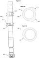
- FIG. 1 shows a side view of a prior art slick assembly steerable PDM directional assembly 100 .
- Assembly 100 includes bend 101 , drill bit 102 , and kick/wear pad 103 .
- FIG. 1 a shows a cross section 104 of kick/wear pad 103 taken across a-a of FIG. 1 .
- FIG. 2 shows a side view of a prior art near bit stabilized steerable PDM directional assembly 200 .
- Assembly 200 includes bend 101 , drill bit 102 , and kick/wear pad 103 . It also includes near bit stabilizer 205 .
- FIG. 2 a shows a cross section 104 of kick/wear pad 103 taken across a-a of FIG. 2 .
- FIG. 2 b shows a cross section 206 of near bit stabilizer 205 taken across b-b of FIG. 2 with symmetric circumferential blades shown at 207 .
- FIG. 3 shows a side view of a prior art fully stabilized steerable PDM directional assembly 300 .
- Assembly 300 includes bend 101 , drill bit 102 , and kick/wear pad 103 . It also includes near bit stabilizer 205 and above bend stabilizer 308 .
- FIG. 3 a shows a cross section 104 of kick/wear pad 103 taken across a-a of FIG. 3 .
- FIG. 3 b shows a cross section 206 of near bit stabilizer 205 taken across b-b of FIG. 3 with symmetric circumferential blades shown at 207 .
- FIG. 3 c shows a cross section 309 of above bend stabilizer 308 taken across c-c of FIG. 3 with symmetric circumferential blades shown at 310 .
- FIG. 4 shows a generalized cross section view 400 of aspects of the technology of the steerable PDM directional assembly of this application.
- FIG. 4 shows center point 490 , nominal bit diameter 491 , housing or sleeve minor diameter 492 , nominal bit radius 493 , and nominal housing or sleeve minor radius 494 .
- FIG. 4 also shows demarcation diameter 495 .
- Radial zone 496 falls inside the demarcation diameter 495 and covers the zone of maximum radial surface of a secondary positioning element structure of a given near bit or above bend positioning element. In the technology of the present application, radial zone 496 is greater than or equal to the housing or sleeve minor diameter 492 and is less than or equal to 0.90 of the nominal bit radius 493 .
- Radial zone 497 falls outside the demarcation diameter 495 and covers the zone of maximum radial surface of a primary positioning element structure of a given near bit or above bend positioning element. In the technology of the present application, radial zone 497 is greater than or equal to 0.91 of the nominal bit radius 493 and less than or equal to 1.05 of the nominal bit radius 493 . From the above description, it can be seen that the demarcation diameter 495 occupies the narrow zone between 0.90 and 0.91 of the nominal bit radius 493 .
- FIG. 5 shows a side view of an assembly 500 consistent with one embodiment of the technology of the present application.
- Assembly 500 includes bend 101 , drill bit 102 , and kick/wear pad 103 . It also shows above bend positioning element 509 .
- FIG. 5 a shows cross section 104 of kick/wear pad 103 taken across a-a of FIG. 5 .
- FIG. 5 d shows cross section 510 of above bend positioning element 509 taken across d-d of FIG. 5 .
- FIG. 5 d also shows primary positioning element structure 511 .
- FIG. 6 shows a side view of an assembly 600 consistent with another embodiment of the technology of the present application.
- Assembly 600 includes bend 101 , drill bit 102 , and kick/wear pad 103 .
- Assembly 600 also shows above bend positioning element 609 .
- FIG. 6 a shows cross section 104 of kick/wear pad 103 taken across a-a of FIG. 6 .
- FIG. 6 e shows cross section 610 of above bend positioning element 609 taken across e-e of FIG. 6 .
- FIG. 6 e also shows primary positioning element structure blades 611 .
- FIG. 7 shows a side view of an assembly 700 consistent with another embodiment of the technology of the present application.
- Assembly 700 includes bend 101 , drill bit 102 , and kick/wear pad 103 .
- Assembly 700 also shows above bend positioning element 509 .
- Assembly 700 also shows near bit positioning element 715 .
- kick/wear pad 103 is optional at designer discretion in the embodiment of FIG. 7 .
- FIG. 7 a shows cross section 104 of kick/wear pad 103 taken across a-a of FIG. 7 . It should be noted that kick/wear pad 103 is optional at designer discretion in the embodiment of FIG. 7 .
- FIG. 7 d shows cross section 510 of above bend positioning element 509 taken across d-d of FIG. 7 .
- FIG. 7 d also shows primary positioning element structure 511 .
- FIG. 7 f shows cross section 716 of near bit positioning element 715 taken across f-f of FIG. 7 .
- FIG. 7 f also shows primary positioning element structure 717 .
- FIG. 8 shows a side view of an assembly 800 consistent with another embodiment of the technology of the present application.
- Assembly 800 includes bend 101 , drill bit 102 , and kick/wear pad 103 .
- Assembly 800 also shows above bend positioning element 609 .
- Assembly 800 also shows near bit positioning element 817 .
- kick/wear pad 103 is optional at designer discretion in the embodiment of FIG. 8 .
- FIG. 8 a shows cross section 104 of kick/wear pad 103 taken across a-a of FIG. 8 . It should be noted that kick/wear pad 103 is optional at designer discretion in the embodiment of FIG. 8 .
- FIG. 8 e shows cross section 610 of above bend positioning element 609 taken across e-e of FIG. 8 .
- FIG. 8 e also shows primary positioning element structure blades 611 .
- FIG. 8 g shows cross section 818 of near bit positioning element 817 taken across g-g of FIG. 8 .
- FIG. 8 g also shows primary positioning element structure blades 819 .
- FIG. 9 i shows a side view of an assembly 900 consistent with another embodiment of the technology of the present application.
- Assembly 900 includes bend 101 , drill bit 102 , and kick/wear pad 103 .
- Assembly 900 also shows above bend positioning element 919 .
- Assembly 900 also shows near bit positioning element 715 .
- kick/wear pad 103 is optional at designer discretion in the embodiment of FIG. 8 .
- FIG. 9 a shows cross section 104 of kick/wear pad 103 taken across a-a of FIG. 9 i . It should be noted that kick/wear pad 103 is optional at designer discretion in the embodiment of FIG. 9 i.
- FIG. 9 g shows cross section 818 of near bit positioning element 817 taken across g-g of FIG. 9 i .
- FIG. 9 g also shows primary positioning element structure blades 819 .
- FIG. 9 h shows cross section 920 of above bend positioning element 919 .
- FIG. 9 h also shows spiraled primary positioning element structure blades 921 .
- FIG. 9 j shows a scribe side view of assembly 900 .
- FIG. 9 j also shows scribe side of above bend positioning element 919 and scribe mark 922 .
- FIG. 10 a shows a cross section of an assembly 1000 of an alternative embodiment of a positioning element of the technology.
- Assembly 1000 includes two primary positioning element structure surfaces at 1001 and three secondary positioning element structure surfaces at 1002 .
- FIG. 10 b shows a cross section of an assembly 1010 of an additional alternative embodiment of a positioning element of the technology.
- Assembly 1010 includes three primary positioning element structure surfaces at 1011 and two secondary positioning element structure surfaces at 1012 .
- FIG. 10 c shows a cross section of an assembly 1020 of an additional alternative embodiment of a positioning element of the technology.
- Assembly 1010 includes one primary positioning element structure surface at 1021 and five secondary positioning element structure surfaces at 1022 .
- the degrees of arc of the outer surfaces of the primary element structure may cover as little as approximately 25 degrees as in 10 c , or greater amounts of degrees of arc as in 10 a and 10 b .
- the maximum degrees of arc of the outer surfaces of the primary element structure does not exceed 175 degrees.
- FIG. 11 is a chart of geometrically calculated build rates (BUR) for various assembly bend angles of assemblies employing the technology of the present application.
- BUR geometrically calculated build rates
- the designer is free to radius or bevel the edges of the outer surfaces of the positioning element structures. Additionally the designer may choose to bevel, taper or curve the proximal and/or distal ends of the outer surfaces of the positioning element structures to transition or blend them with the tool or sleeve body.
- the designer may taper the proximal portion of the primary outer surfaces of a near bit positioning element structure in order to reduce the stresses encountered in the slide to rotate stress condition referred to previously.
- the designer may choose to not employ traditional kick/wear pad at or near the bend of the assembly. It should be understood that the use of traditional kick/wear pad is at the discretion of the designer.
- a modified bottom hole assembly according to the teachings of this application by selectively grinding or milling some of the outer surfaces of the blades of traditional directional BHA stabilizers to allow them to meet the limits of secondary outer positioning element structures while leaving the remaining blades unground or unmilled, or adding material to the remaining blades such as by welding, so as to cause them or allow them to meet the limits of primary outer positioning element structures.
- flat top or dome top tungsten carbide or PDC inserts can be inserted into sockets formed in the primary outer positioning structure. These inserts can be placed for an exposure above the pad or surface of the positioning element primary structure to allow the structure to meet the limits of the primary outer surfaces of the technology.
Landscapes
- Engineering & Computer Science (AREA)
- Life Sciences & Earth Sciences (AREA)
- Geology (AREA)
- Mining & Mineral Resources (AREA)
- Physics & Mathematics (AREA)
- Environmental & Geological Engineering (AREA)
- Fluid Mechanics (AREA)
- General Life Sciences & Earth Sciences (AREA)
- Geochemistry & Mineralogy (AREA)
- Mechanical Engineering (AREA)
- Earth Drilling (AREA)
Abstract
Description
Claims (11)
Priority Applications (3)
| Application Number | Priority Date | Filing Date | Title |
|---|---|---|---|
| US15/808,798 US11255136B2 (en) | 2016-12-28 | 2017-11-09 | Bottom hole assemblies for directional drilling |
| PCT/US2017/066745 WO2018125616A1 (en) | 2016-12-28 | 2017-12-15 | Bottom hole assemblies for directional drilling |
| CA3048144A CA3048144C (en) | 2016-12-28 | 2017-12-15 | Bottom hole assemblies for directional drilling |
Applications Claiming Priority (3)
| Application Number | Priority Date | Filing Date | Title |
|---|---|---|---|
| US201662439843P | 2016-12-28 | 2016-12-28 | |
| US15/667,704 US10890030B2 (en) | 2016-12-28 | 2017-08-03 | Method, apparatus by method, and apparatus of guidance positioning members for directional drilling |
| US15/808,798 US11255136B2 (en) | 2016-12-28 | 2017-11-09 | Bottom hole assemblies for directional drilling |
Related Parent Applications (1)
| Application Number | Title | Priority Date | Filing Date |
|---|---|---|---|
| US15/667,704 Continuation-In-Part US10890030B2 (en) | 2016-12-28 | 2017-08-03 | Method, apparatus by method, and apparatus of guidance positioning members for directional drilling |
Publications (2)
| Publication Number | Publication Date |
|---|---|
| US20180179831A1 US20180179831A1 (en) | 2018-06-28 |
| US11255136B2 true US11255136B2 (en) | 2022-02-22 |
Family
ID=62625360
Family Applications (1)
| Application Number | Title | Priority Date | Filing Date |
|---|---|---|---|
| US15/808,798 Active 2039-05-21 US11255136B2 (en) | 2016-12-28 | 2017-11-09 | Bottom hole assemblies for directional drilling |
Country Status (2)
| Country | Link |
|---|---|
| US (1) | US11255136B2 (en) |
| WO (1) | WO2018125616A1 (en) |
Families Citing this family (15)
| Publication number | Priority date | Publication date | Assignee | Title |
|---|---|---|---|---|
| US8596385B2 (en) | 2011-12-22 | 2013-12-03 | Hunt Advanced Drilling Technologies, L.L.C. | System and method for determining incremental progression between survey points while drilling |
| US8210283B1 (en) | 2011-12-22 | 2012-07-03 | Hunt Energy Enterprises, L.L.C. | System and method for surface steerable drilling |
| US9297205B2 (en) | 2011-12-22 | 2016-03-29 | Hunt Advanced Drilling Technologies, LLC | System and method for controlling a drilling path based on drift estimates |
| US11085283B2 (en) | 2011-12-22 | 2021-08-10 | Motive Drilling Technologies, Inc. | System and method for surface steerable drilling using tactical tracking |
| US11106185B2 (en) | 2014-06-25 | 2021-08-31 | Motive Drilling Technologies, Inc. | System and method for surface steerable drilling to provide formation mechanical analysis |
| US9428961B2 (en) | 2014-06-25 | 2016-08-30 | Motive Drilling Technologies, Inc. | Surface steerable drilling system for use with rotary steerable system |
| US11933158B2 (en) | 2016-09-02 | 2024-03-19 | Motive Drilling Technologies, Inc. | System and method for mag ranging drilling control |
| WO2018106248A1 (en) * | 2016-12-08 | 2018-06-14 | Halliburton Energy Services, Inc. | Bottomhole assembly (bha) stabilizer or reamer position adjustment methods and systems employing a cost function |
| US10890030B2 (en) | 2016-12-28 | 2021-01-12 | Xr Lateral Llc | Method, apparatus by method, and apparatus of guidance positioning members for directional drilling |
| US10830033B2 (en) | 2017-08-10 | 2020-11-10 | Motive Drilling Technologies, Inc. | Apparatus and methods for uninterrupted drilling |
| AU2018313280B8 (en) | 2017-08-10 | 2023-09-21 | Motive Drilling Technologies, Inc. | Apparatus and methods for automated slide drilling |
| US11111978B2 (en) | 2017-12-14 | 2021-09-07 | Xr Reserve, Llc | Mechanical force breaker |
| US11466556B2 (en) | 2019-05-17 | 2022-10-11 | Helmerich & Payne, Inc. | Stall detection and recovery for mud motors |
| US11613929B2 (en) | 2019-11-08 | 2023-03-28 | Xr Dynamics Llc | Dynamic drilling systems and methods |
| US11885212B2 (en) | 2021-07-16 | 2024-01-30 | Helmerich & Payne Technologies, Llc | Apparatus and methods for controlling drilling |
Citations (167)
| Publication number | Priority date | Publication date | Assignee | Title |
|---|---|---|---|---|
| US356154A (en) | 1887-01-18 | neelands | ||
| US1638337A (en) | 1925-05-25 | 1927-08-09 | Edward S Hutton | Rotary well drill |
| US1667155A (en) | 1927-03-18 | 1928-04-24 | Zalmon B Higdon | Drilling bit |
| US2919897A (en) | 1958-07-07 | 1960-01-05 | Regan Forge & Eng Co | Deflection drilling tool |
| US3061025A (en) | 1959-03-31 | 1962-10-30 | Hughes Tool Co | Unitized drilling bit |
| US3156310A (en) * | 1959-12-07 | 1964-11-10 | Eastman Oil Well Survey Co | Stabilized knuckle joint |
| US3159224A (en) | 1960-12-30 | 1964-12-01 | Atlantic Refining Co | Underdrilling rotary bit |
| US3224513A (en) | 1962-11-07 | 1965-12-21 | Jr Frank G Weeden | Apparatus for downhole drilling |
| US3561549A (en) * | 1968-06-07 | 1971-02-09 | Smith Ind International Inc | Slant drilling tools for oil wells |
| US3880246A (en) | 1972-09-25 | 1975-04-29 | Ralph J Farris | Optionally stabilized drilling tool, and method of use |
| US3882946A (en) | 1974-04-24 | 1975-05-13 | Rolen Arsenievich Ioannesian | Turbodrill |
| US4270619A (en) | 1979-10-03 | 1981-06-02 | Base Jimmy D | Downhole stabilizing tool with actuator assembly and method for using same |
| US4373592A (en) | 1980-11-28 | 1983-02-15 | Mobil Oil Corporation | Rotary drilling drill string stabilizer-cuttings grinder |
| US4385669A (en) | 1981-08-21 | 1983-05-31 | Paul Knutsen | Integral blade cylindrical gauge stabilizer reamer |
| US4407377A (en) | 1982-04-16 | 1983-10-04 | Russell Larry R | Surface controlled blade stabilizer |
| US4456080A (en) | 1980-09-19 | 1984-06-26 | Holbert Don R | Stabilizer method and apparatus for earth-boring operations |
| US4465147A (en) * | 1982-02-02 | 1984-08-14 | Shell Oil Company | Method and means for controlling the course of a bore hole |
| US4485879A (en) | 1982-08-25 | 1984-12-04 | Shell Oil Company | Downhole motor and method for directional drilling of boreholes |
| US4491187A (en) | 1982-06-01 | 1985-01-01 | Russell Larry R | Surface controlled auxiliary blade stabilizer |
| US4492276A (en) | 1982-11-17 | 1985-01-08 | Shell Oil Company | Down-hole drilling motor and method for directional drilling of boreholes |
| US4523652A (en) | 1983-07-01 | 1985-06-18 | Atlantic Richfield Company | Drainhole drilling assembly and method |
| US4577701A (en) | 1984-08-08 | 1986-03-25 | Mobil Oil Corporation | System of drilling deviated wellbores |
| US4618010A (en) | 1986-02-18 | 1986-10-21 | Team Engineering And Manufacturing, Inc. | Hole opener |
| US4623026A (en) * | 1982-06-03 | 1986-11-18 | Kemp Billy W | Method and apparatus of a self-aligning sleeve for the correction of the direction of deviated boreholes |
| US4667751A (en) | 1985-10-11 | 1987-05-26 | Smith International, Inc. | System and method for controlled directional drilling |
| US4690229A (en) | 1986-01-22 | 1987-09-01 | Raney Richard C | Radially stabilized drill bit |
| US4697651A (en) | 1986-12-22 | 1987-10-06 | Mobil Oil Corporation | Method of drilling deviated wellbores |
| US4715453A (en) | 1986-10-30 | 1987-12-29 | Team Construction And Fabrication, Inc. | Drilling deviation control tool |
| US4729438A (en) | 1986-07-03 | 1988-03-08 | Eastman Christensen Co, | Stabilizer for navigational drilling |
| US4739843A (en) * | 1986-05-12 | 1988-04-26 | Sidewinder Tool Joint Venture | Apparatus for lateral drilling in oil and gas wells |
| US4775017A (en) | 1986-04-11 | 1988-10-04 | Drilex Uk Limited | Drilling using downhole drilling tools |
| US4807708A (en) * | 1985-12-02 | 1989-02-28 | Drilex Uk Limited And Eastman Christensen Company | Directional drilling of a drill string |
| US4842083A (en) | 1986-01-22 | 1989-06-27 | Raney Richard C | Drill bit stabilizer |
| US4848490A (en) | 1986-07-03 | 1989-07-18 | Anderson Charles A | Downhole stabilizers |
| US4862974A (en) | 1988-12-07 | 1989-09-05 | Amoco Corporation | Downhole drilling assembly, apparatus and method utilizing drilling motor and stabilizer |
| US4877092A (en) | 1988-04-15 | 1989-10-31 | Teleco Oilfield Services Inc. | Near bit offset stabilizer |
| US5010789A (en) | 1989-02-21 | 1991-04-30 | Amoco Corporation | Method of making imbalanced compensated drill bit |
| US5042596A (en) | 1989-02-21 | 1991-08-27 | Amoco Corporation | Imbalance compensated drill bit |
| US5050692A (en) * | 1987-08-07 | 1991-09-24 | Baker Hughes Incorporated | Method for directional drilling of subterranean wells |
| US5099929A (en) | 1990-05-04 | 1992-03-31 | Dresser Industries, Inc. | Unbalanced PDC drill bit with right hand walk tendencies, and method of drilling right hand bore holes |
| US5099931A (en) * | 1988-02-02 | 1992-03-31 | Eastman Christensen Company | Method and apparatus for optional straight hole drilling or directional drilling in earth formations |
| US5115872A (en) | 1990-10-19 | 1992-05-26 | Anglo Suisse, Inc. | Directional drilling system and method for drilling precise offset wellbores from a main wellbore |
| US5131479A (en) * | 1990-03-07 | 1992-07-21 | Institut Francais Du Petrole | Rotary drilling device comprising means for adjusting the azimuth angle of the path of the drilling tool and corresponding drilling process |
| US5139094A (en) | 1991-02-01 | 1992-08-18 | Anadrill, Inc. | Directional drilling methods and apparatus |
| US5159577A (en) | 1990-10-09 | 1992-10-27 | Baroid Technology, Inc. | Technique for reducing whirling of a drill string |
| US5181576A (en) | 1991-02-01 | 1993-01-26 | Anadrill, Inc. | Downhole adjustable stabilizer |
| US5318137A (en) * | 1992-10-23 | 1994-06-07 | Halliburton Company | Method and apparatus for adjusting the position of stabilizer blades |
| US5320179A (en) | 1992-08-06 | 1994-06-14 | Slimdril International Inc. | Steering sub for flexible drilling |
| US5333699A (en) | 1992-12-23 | 1994-08-02 | Baroid Technology, Inc. | Drill bit having polycrystalline diamond compact cutter with spherical first end opposite cutting end |
| US5343967A (en) * | 1984-05-12 | 1994-09-06 | Baker Hughes Incorporated | Apparatus for optional straight or directional drilling underground formations |
| US5361859A (en) | 1993-02-12 | 1994-11-08 | Baker Hughes Incorporated | Expandable gage bit for drilling and method of drilling |
| US5458208A (en) | 1994-07-05 | 1995-10-17 | Clarke; Ralph L. | Directional drilling using a rotating slide sub |
| EP0530045B1 (en) | 1991-08-30 | 1997-04-23 | Camco Drilling Group Limited | Modulated bias units for steerable rotary drilling systems |
| US5673763A (en) | 1994-06-04 | 1997-10-07 | Camco Drilling Group Ltd. Of Hycalog | Modulated bias unit for rotary drilling |
| US5812068A (en) * | 1994-12-12 | 1998-09-22 | Baker Hughes Incorporated | Drilling system with downhole apparatus for determining parameters of interest and for adjusting drilling direction in response thereto |
| US5857531A (en) | 1997-04-10 | 1999-01-12 | Halliburton Energy Services, Inc. | Bottom hole assembly for directional drilling |
| US5904213A (en) | 1995-10-10 | 1999-05-18 | Camco International (Uk) Limited | Rotary drill bits |
| US5931239A (en) | 1995-05-19 | 1999-08-03 | Telejet Technologies, Inc. | Adjustable stabilizer for directional drilling |
| US5937958A (en) | 1997-02-19 | 1999-08-17 | Smith International, Inc. | Drill bits with predictable walk tendencies |
| US5957223A (en) | 1997-03-05 | 1999-09-28 | Baker Hughes Incorporated | Bi-center drill bit with enhanced stabilizing features |
| US5971085A (en) | 1996-11-06 | 1999-10-26 | Camco International (Uk) Limited | Downhole unit for use in boreholes in a subsurface formation |
| US5979570A (en) | 1995-04-05 | 1999-11-09 | Mcloughlin; Stephen John | Surface controlled wellbore directional steering tool |
| CA2291922A1 (en) | 1998-12-11 | 2000-06-11 | Schlumberger Canada Limited | Rotary steerable well drilling system utilizing sliding sleeve |
| US6073707A (en) | 1998-03-11 | 2000-06-13 | Canadian Downhole Drill Systems Inc. | Downhole sub with kick pad for directional drilling |
| US6109372A (en) | 1999-03-15 | 2000-08-29 | Schlumberger Technology Corporation | Rotary steerable well drilling system utilizing hydraulic servo-loop |
| US6116356A (en) * | 1996-10-09 | 2000-09-12 | Baker Hughes Incorporated | Reaming apparatus and method with enhanced stability and transition from pilot hole to enlarged bore diameter |
| US6158533A (en) | 1998-04-09 | 2000-12-12 | Halliburton Energy Services, Inc. | Adjustable gauge downhole drilling assembly |
| US6186251B1 (en) | 1998-07-27 | 2001-02-13 | Baker Hughes Incorporated | Method of altering a balance characteristic and moment configuration of a drill bit and drill bit |
| US6213226B1 (en) * | 1997-12-04 | 2001-04-10 | Halliburton Energy Services, Inc. | Directional drilling assembly and method |
| US6257356B1 (en) | 1999-10-06 | 2001-07-10 | Aps Technology, Inc. | Magnetorheological fluid apparatus, especially adapted for use in a steerable drill string, and a method of using same |
| US6325162B1 (en) * | 1997-12-04 | 2001-12-04 | Halliburton Energy Services, Inc. | Bit connector |
| US6349780B1 (en) | 2000-08-11 | 2002-02-26 | Baker Hughes Incorporated | Drill bit with selectively-aggressive gage pads |
| US20020056574A1 (en) * | 2000-03-22 | 2002-05-16 | Harvey Peter R. | Stabilizer for use in a drill string |
| US20020070021A1 (en) | 1998-05-13 | 2002-06-13 | Van Drentham-Susman Hector F.A. | Guide device |
| US6427792B1 (en) | 2000-07-06 | 2002-08-06 | Camco International (Uk) Limited | Active gauge cutting structure for earth boring drill bits |
| US20020112892A1 (en) * | 2001-02-16 | 2002-08-22 | Taylor Kyle Lamar | Rotary steering tool system for directional drilling |
| US20020175006A1 (en) | 1999-01-25 | 2002-11-28 | Findley Sidney L. | Drill bits and other articles of manufacture including a layer-manufactured shell integrally secured to a cast structure and methods and molds for fabricating same |
| US20030010534A1 (en) | 1998-12-21 | 2003-01-16 | Chen Chen-Kang D. | Steerable drilling system and method |
| US20030024742A1 (en) | 2001-06-12 | 2003-02-06 | George Swietlik | Steerable downhole tools |
| US6523623B1 (en) | 2001-05-30 | 2003-02-25 | Validus International Company, Llc | Method and apparatus for determining drilling paths to directional targets |
| US6722453B1 (en) | 1998-12-14 | 2004-04-20 | Jay C. A. Crooks | Stabilized downhole drilling motor |
| US6742605B2 (en) | 2002-06-12 | 2004-06-01 | Leo A. Martini | Percussion tool for generic downhole fluid motors |
| US20040216921A1 (en) * | 1998-11-10 | 2004-11-04 | Baker Hughes Incorporated | Self-controlled directional drilling systems and methods |
| US20050096847A1 (en) | 2000-10-11 | 2005-05-05 | Smith International, Inc. | Methods for modeling, designing, and optimizing the performance of drilling tool assemblies |
| US20050150692A1 (en) * | 2003-11-05 | 2005-07-14 | Baker Hughes Incorporated | Directional cased hole side track method applying rotary closed loop system and casing mill |
| US20050236187A1 (en) | 2002-12-16 | 2005-10-27 | Chen Chen-Kang D | Drilling with casing |
| US6991046B2 (en) | 2003-11-03 | 2006-01-31 | Reedhycalog, L.P. | Expandable eccentric reamer and method of use in drilling |
| US20060196697A1 (en) | 2002-04-30 | 2006-09-07 | Raney Richard C | Stabilizing system and methods for a drill bit |
| US20070007000A1 (en) | 2005-07-06 | 2007-01-11 | Smith International, Inc. | Method of drilling an enlarged sidetracked well bore |
| US7207398B2 (en) | 2001-07-16 | 2007-04-24 | Shell Oil Company | Steerable rotary drill bit assembly with pilot bit |
| US20070163810A1 (en) | 2006-01-18 | 2007-07-19 | Smith International, Inc. | Flexible directional drilling apparatus and method |
| US20070205024A1 (en) | 2005-11-30 | 2007-09-06 | Graham Mensa-Wilmot | Steerable fixed cutter drill bit |
| US20070235227A1 (en) | 2006-04-07 | 2007-10-11 | Halliburton Energy Services, Inc. | Steering tool |
| US20070272445A1 (en) | 2006-05-26 | 2007-11-29 | Smith International, Inc. | Drill bit with assymetric gage pad configuration |
| US20080000693A1 (en) | 2005-02-11 | 2008-01-03 | Richard Hutton | Steerable rotary directional drilling tool for drilling boreholes |
| US20080047754A1 (en) | 2006-08-25 | 2008-02-28 | Smith International, Inc. | Passive vertical drilling motor stabilization |
| US20080053707A1 (en) | 2006-06-02 | 2008-03-06 | Schlumberger Technology Corporation | System and method for reducing the borehole gap for downhole formation testing sensors |
| US20080075618A1 (en) | 2006-09-19 | 2008-03-27 | Schlumberger Technology Corporation | Metal Powder Layered Apparatus for Downhole Use |
| US20080115974A1 (en) | 2006-11-16 | 2008-05-22 | Ashley Johnson | Steerable drilling system |
| US20080190665A1 (en) | 2004-01-28 | 2008-08-14 | Halliburton Energy Services, Inc. | Rotary Vector Gear for Use in Rotary Steerable Tools |
| US20080271923A1 (en) | 2007-05-03 | 2008-11-06 | David John Kusko | Flow hydraulic amplification for a pulsing, fracturing, and drilling (PFD) device |
| US20090000823A1 (en) | 2007-06-29 | 2009-01-01 | Schlumberger Technology Corporation | Method of Automatically controlling the Trajectory of a Drilled Well |
| US20090044981A1 (en) | 2007-08-15 | 2009-02-19 | Schlumberger Technology Corporation | Method and system for steering a directional drilling system |
| US20090044980A1 (en) | 2007-08-15 | 2009-02-19 | Schlumberger Technology Corporation | System and method for directional drilling a borehole with a rotary drilling system |
| US20090065262A1 (en) | 2007-09-11 | 2009-03-12 | Downton Geoffrey C | Drill bit |
| US20090107722A1 (en) | 2007-10-24 | 2009-04-30 | Schlumberger Technology Corporation | Morphible bit |
| US7562725B1 (en) | 2003-07-10 | 2009-07-21 | Broussard Edwin J | Downhole pilot bit and reamer with maximized mud motor dimensions |
| US20090188720A1 (en) | 2007-08-15 | 2009-07-30 | Schlumberger Technology Corporation | System and method for drilling |
| US20100006341A1 (en) | 2008-07-11 | 2010-01-14 | Schlumberger Technology Corporation | Steerable piloted drill bit, drill system, and method of drilling curved boreholes |
| US7831419B2 (en) | 2005-01-24 | 2010-11-09 | Smith International, Inc. | PDC drill bit with cutter design optimized with dynamic centerline analysis having an angular separation in imbalance forces of 180 degrees for maximum time |
| US20100307837A1 (en) | 2009-06-05 | 2010-12-09 | Varel International, Ind., L.P. | Casing bit and casing reamer designs |
| US20110031025A1 (en) | 2009-08-04 | 2011-02-10 | Baker Hughes Incorporated | Drill Bit With An Adjustable Steering Device |
| US20110247816A1 (en) | 2008-12-10 | 2011-10-13 | Carter Jr Ernest E | Method and Apparatus for Increasing Well Productivity |
| US20120055713A1 (en) | 2010-08-31 | 2012-03-08 | Baker Hughes Incorporated | Drill Bit with Adjustable Side Force |
| US8162081B2 (en) | 2008-08-28 | 2012-04-24 | Varel International Ind., L.P. | Force balanced asymmetric drilling reamer and methods for force balancing |
| US8176999B2 (en) * | 2004-06-22 | 2012-05-15 | Smart Stabilizer Systems Limited | Steerable drill bit arrangement |
| US8201642B2 (en) | 2009-01-21 | 2012-06-19 | Baker Hughes Incorporated | Drilling assemblies including one of a counter rotating drill bit and a counter rotating reamer, methods of drilling, and methods of forming drilling assemblies |
| US8210283B1 (en) | 2011-12-22 | 2012-07-03 | Hunt Energy Enterprises, L.L.C. | System and method for surface steerable drilling |
| US20120234610A1 (en) | 2011-02-10 | 2012-09-20 | Smith International, Inc. | Cutting structures for fixed cutter drill bit and other downhole cutting tools |
| US8316968B2 (en) | 2009-05-01 | 2012-11-27 | Smith International, Inc. | Rolling cone drill bit having sharp cutting elements in a zone of interest |
| US20130043076A1 (en) * | 2011-08-19 | 2013-02-21 | Precision Energy Services, Inc. | Rotary Steerable Assembly Inhibiting Counterclockwise Whirl During Directional Drilling |
| US8448722B2 (en) | 2010-05-04 | 2013-05-28 | Arrival Oil Tools, Inc. | Drilling stabilizer |
| US8448721B2 (en) | 2007-12-19 | 2013-05-28 | Schlumberger Technology Corporation | Directional drilling system |
| US20130180782A1 (en) | 2012-01-12 | 2013-07-18 | Baker Hughes Incorporated | Turbine Driven Reaming Bit with Blades and Cutting Structure Extending into Concave Nose |
| US8550190B2 (en) | 2010-04-01 | 2013-10-08 | David R. Hall | Inner bit disposed within an outer bit |
| US20140097026A1 (en) | 2012-09-24 | 2014-04-10 | Schlumberger Technology Corporation | Positive Displacement Motor (PDM) Rotary Steerable System (RSS) And Apparatus |
| US20140110178A1 (en) | 2012-06-12 | 2014-04-24 | Halliburton Energy Services, Inc. | Modular rotary steerable actuators, steering tools, and rotary steerable drilling systems with modular actuators |
| US8757298B2 (en) | 2011-04-26 | 2014-06-24 | Edwin J. Broussard, JR. | Method and apparatus for dual speed, dual torque drilling |
| US8763726B2 (en) | 2007-08-15 | 2014-07-01 | Schlumberger Technology Corporation | Drill bit gauge pad control |
| USD710176S1 (en) | 2013-08-15 | 2014-08-05 | Black & Decker Inc. | Sleeve for screwdriving bit |
| USD710175S1 (en) | 2013-08-15 | 2014-08-05 | Black & Decker Inc. | Sleeve for screwdriving bit |
| USD710174S1 (en) | 2013-08-15 | 2014-08-05 | Black & Decker Inc. | Sleeve for screwdriving bit |
| US20140246209A1 (en) | 2011-10-11 | 2014-09-04 | Packers Plus Energy Services Inc. | Wellbore actuators, treatment strings and methods |
| US20140246234A1 (en) | 2013-03-04 | 2014-09-04 | Drilformance Technologies, Llc | Drilling apparatus and method |
| USD713706S1 (en) | 2012-03-05 | 2014-09-23 | Robert Bosch Gmbh | Tool holder portion of an impact driver |
| US20140311801A1 (en) | 2013-04-17 | 2014-10-23 | Baker Hughes Incorporated | Drill Bit with Self-Adjusting Pads |
| USD717626S1 (en) | 2013-03-02 | 2014-11-18 | Ronald W. Dickrede | Adaptor for holding a tap threading device |
| US8905159B2 (en) | 2009-12-15 | 2014-12-09 | Schlumberger Technology Corporation | Eccentric steering device and methods of directional drilling |
| US20140379133A1 (en) | 2013-06-21 | 2014-12-25 | Directional Control Systems International (DCSI) Inc. | Methods and systems for monitoring directional drilling |
| US20150101864A1 (en) | 2013-10-12 | 2015-04-16 | Mark May | Intelligent reamer for rotary/sliding drilling system and method |
| US9016400B2 (en) | 2010-09-09 | 2015-04-28 | National Oilwell Varco, L.P. | Downhole rotary drilling apparatus with formation-interfacing members and control system |
| US20150122551A1 (en) | 2012-05-30 | 2015-05-07 | Halliburton Energy Services, Inc. | Rotary drill bit and method for designing a rotary drill bit for directional and horizontal drilling |
| US20150152723A1 (en) | 2012-07-05 | 2015-06-04 | Halliburton Energy Services, Inc. | Displaceable components in drilling operations |
| USD731277S1 (en) | 2013-08-16 | 2015-06-09 | Magna-Sonic Stress Testers, Inc. | Barrel for pipe end refacing tool |
| USD732364S1 (en) | 2014-07-02 | 2015-06-23 | Mcginley Engineered Solutions, Llc | Removable chuck |
| US9163460B2 (en) | 2011-10-03 | 2015-10-20 | Extreme Technologies, Llc | Wellbore conditioning system |
| US20150322781A1 (en) | 2012-08-31 | 2015-11-12 | Halliburton Energy Services, Inc. | System and method for analyzing cuttings using an opto-analytical device |
| US20160024846A1 (en) | 2014-07-24 | 2016-01-28 | Schlumberger Technology Corporation | Inverted Wellbore Drilling Motor |
| US20160024848A1 (en) | 2013-03-15 | 2016-01-28 | Tercel Ip Ltd. | Downhole directional drilling assembly |
| US20160115779A1 (en) | 2014-10-17 | 2016-04-28 | Applied Technologies Associates, Inc. | Active Magnetic Azimuthal Toolface for Vertical Borehole Kickoff in Magnetically Perturbed Environments |
| US20160230465A1 (en) * | 2014-04-17 | 2016-08-11 | Halliburton Energy Services, Inc. | Bottom Hole Assembly With Wearable Stabilizer Pad for Directional Steering |
| US20160265287A1 (en) | 2015-03-13 | 2016-09-15 | European Drilling Projects B.V. | Blade stabiliser tool for drill string |
| US20160326863A1 (en) | 2014-10-22 | 2016-11-10 | Halliburton Energy Services, Inc. | Bend angle sensing assembly and method of use |
| US9556683B2 (en) | 2012-12-03 | 2017-01-31 | Ulterra Drilling Technologies, L.P. | Earth boring tool with improved arrangement of cutter side rakes |
| US20170044833A1 (en) * | 2015-08-06 | 2017-02-16 | Cathedral Energy Services Ltd. | Directional drilling motor |
| US9605482B2 (en) | 2015-03-05 | 2017-03-28 | Halliburton Energy Services, Inc. | Directional drilling with adjustable bent housings |
| US20170130533A1 (en) | 2014-07-31 | 2017-05-11 | Halliburton Energy Services, Inc. | Force self-balanced drill bit |
| USD786645S1 (en) | 2015-11-03 | 2017-05-16 | Z Drilling Holdings, Inc. | Reamer |
| USD793831S1 (en) | 2016-02-03 | 2017-08-08 | Mcginley Engineered Solutions, Llc | Removable chuck |
| USD793833S1 (en) | 2016-02-03 | 2017-08-08 | Mcginley Engineered Solutions, Llc | Removable chuck |
| USD793832S1 (en) | 2016-02-03 | 2017-08-08 | Mcginley Engineered Solutions, Llc | Removable chuck |
| US20170234071A1 (en) | 2016-02-16 | 2017-08-17 | Extreme Rock Destruction LLC | Drilling machine |
| US20170241207A1 (en) * | 2011-04-08 | 2017-08-24 | Extreme Technologies, Llc | Method and apparatus for steering a drill string and reaming well bore surfaces nearer the center of drift |
| US20170342778A1 (en) | 2014-12-30 | 2017-11-30 | Halliburton Energy Services, Inc. | Downhole tool surfaces configured to reduce drag forces and erosion during exposure to fluid flow |
| US20180073301A1 (en) | 2016-09-12 | 2018-03-15 | Hypersciences, Inc. | Augmented drilling system |
| USD813003S1 (en) | 2016-11-15 | 2018-03-20 | Wintek Tools Co., Ltd. | Tool adapter |
| US20190055810A1 (en) | 2015-12-29 | 2019-02-21 | Halliburton Energy Services, Inc. | Wellbore isolation devices with slip bands and wear bands having modified surfaces |
-
2017
- 2017-11-09 US US15/808,798 patent/US11255136B2/en active Active
- 2017-12-15 WO PCT/US2017/066745 patent/WO2018125616A1/en not_active Ceased
Patent Citations (174)
| Publication number | Priority date | Publication date | Assignee | Title |
|---|---|---|---|---|
| US356154A (en) | 1887-01-18 | neelands | ||
| US1638337A (en) | 1925-05-25 | 1927-08-09 | Edward S Hutton | Rotary well drill |
| US1667155A (en) | 1927-03-18 | 1928-04-24 | Zalmon B Higdon | Drilling bit |
| US2919897A (en) | 1958-07-07 | 1960-01-05 | Regan Forge & Eng Co | Deflection drilling tool |
| US3061025A (en) | 1959-03-31 | 1962-10-30 | Hughes Tool Co | Unitized drilling bit |
| US3156310A (en) * | 1959-12-07 | 1964-11-10 | Eastman Oil Well Survey Co | Stabilized knuckle joint |
| US3159224A (en) | 1960-12-30 | 1964-12-01 | Atlantic Refining Co | Underdrilling rotary bit |
| US3224513A (en) | 1962-11-07 | 1965-12-21 | Jr Frank G Weeden | Apparatus for downhole drilling |
| US3561549A (en) * | 1968-06-07 | 1971-02-09 | Smith Ind International Inc | Slant drilling tools for oil wells |
| US3880246A (en) | 1972-09-25 | 1975-04-29 | Ralph J Farris | Optionally stabilized drilling tool, and method of use |
| US3882946A (en) | 1974-04-24 | 1975-05-13 | Rolen Arsenievich Ioannesian | Turbodrill |
| US4270619A (en) | 1979-10-03 | 1981-06-02 | Base Jimmy D | Downhole stabilizing tool with actuator assembly and method for using same |
| US4456080A (en) | 1980-09-19 | 1984-06-26 | Holbert Don R | Stabilizer method and apparatus for earth-boring operations |
| US4373592A (en) | 1980-11-28 | 1983-02-15 | Mobil Oil Corporation | Rotary drilling drill string stabilizer-cuttings grinder |
| US4385669A (en) | 1981-08-21 | 1983-05-31 | Paul Knutsen | Integral blade cylindrical gauge stabilizer reamer |
| US4465147A (en) * | 1982-02-02 | 1984-08-14 | Shell Oil Company | Method and means for controlling the course of a bore hole |
| US4407377A (en) | 1982-04-16 | 1983-10-04 | Russell Larry R | Surface controlled blade stabilizer |
| US4491187A (en) | 1982-06-01 | 1985-01-01 | Russell Larry R | Surface controlled auxiliary blade stabilizer |
| US4623026A (en) * | 1982-06-03 | 1986-11-18 | Kemp Billy W | Method and apparatus of a self-aligning sleeve for the correction of the direction of deviated boreholes |
| US4485879A (en) | 1982-08-25 | 1984-12-04 | Shell Oil Company | Downhole motor and method for directional drilling of boreholes |
| US4492276B1 (en) | 1982-11-17 | 1991-07-30 | Shell Oil Co | |
| US4492276A (en) | 1982-11-17 | 1985-01-08 | Shell Oil Company | Down-hole drilling motor and method for directional drilling of boreholes |
| US4523652A (en) | 1983-07-01 | 1985-06-18 | Atlantic Richfield Company | Drainhole drilling assembly and method |
| US5343967A (en) * | 1984-05-12 | 1994-09-06 | Baker Hughes Incorporated | Apparatus for optional straight or directional drilling underground formations |
| US4577701A (en) | 1984-08-08 | 1986-03-25 | Mobil Oil Corporation | System of drilling deviated wellbores |
| US4667751A (en) | 1985-10-11 | 1987-05-26 | Smith International, Inc. | System and method for controlled directional drilling |
| US4807708A (en) * | 1985-12-02 | 1989-02-28 | Drilex Uk Limited And Eastman Christensen Company | Directional drilling of a drill string |
| US4690229A (en) | 1986-01-22 | 1987-09-01 | Raney Richard C | Radially stabilized drill bit |
| US4842083A (en) | 1986-01-22 | 1989-06-27 | Raney Richard C | Drill bit stabilizer |
| US4618010A (en) | 1986-02-18 | 1986-10-21 | Team Engineering And Manufacturing, Inc. | Hole opener |
| US4775017A (en) | 1986-04-11 | 1988-10-04 | Drilex Uk Limited | Drilling using downhole drilling tools |
| US4739843A (en) * | 1986-05-12 | 1988-04-26 | Sidewinder Tool Joint Venture | Apparatus for lateral drilling in oil and gas wells |
| US4729438A (en) | 1986-07-03 | 1988-03-08 | Eastman Christensen Co, | Stabilizer for navigational drilling |
| US4848490A (en) | 1986-07-03 | 1989-07-18 | Anderson Charles A | Downhole stabilizers |
| US4715453A (en) | 1986-10-30 | 1987-12-29 | Team Construction And Fabrication, Inc. | Drilling deviation control tool |
| US4697651A (en) | 1986-12-22 | 1987-10-06 | Mobil Oil Corporation | Method of drilling deviated wellbores |
| US5050692A (en) * | 1987-08-07 | 1991-09-24 | Baker Hughes Incorporated | Method for directional drilling of subterranean wells |
| US5099931A (en) * | 1988-02-02 | 1992-03-31 | Eastman Christensen Company | Method and apparatus for optional straight hole drilling or directional drilling in earth formations |
| US4877092A (en) | 1988-04-15 | 1989-10-31 | Teleco Oilfield Services Inc. | Near bit offset stabilizer |
| US4862974A (en) | 1988-12-07 | 1989-09-05 | Amoco Corporation | Downhole drilling assembly, apparatus and method utilizing drilling motor and stabilizer |
| US5010789A (en) | 1989-02-21 | 1991-04-30 | Amoco Corporation | Method of making imbalanced compensated drill bit |
| US5042596A (en) | 1989-02-21 | 1991-08-27 | Amoco Corporation | Imbalance compensated drill bit |
| US5131479A (en) * | 1990-03-07 | 1992-07-21 | Institut Francais Du Petrole | Rotary drilling device comprising means for adjusting the azimuth angle of the path of the drilling tool and corresponding drilling process |
| US5099929A (en) | 1990-05-04 | 1992-03-31 | Dresser Industries, Inc. | Unbalanced PDC drill bit with right hand walk tendencies, and method of drilling right hand bore holes |
| US5159577A (en) | 1990-10-09 | 1992-10-27 | Baroid Technology, Inc. | Technique for reducing whirling of a drill string |
| US5115872A (en) | 1990-10-19 | 1992-05-26 | Anglo Suisse, Inc. | Directional drilling system and method for drilling precise offset wellbores from a main wellbore |
| US5139094A (en) | 1991-02-01 | 1992-08-18 | Anadrill, Inc. | Directional drilling methods and apparatus |
| US5181576A (en) | 1991-02-01 | 1993-01-26 | Anadrill, Inc. | Downhole adjustable stabilizer |
| EP0530045B1 (en) | 1991-08-30 | 1997-04-23 | Camco Drilling Group Limited | Modulated bias units for steerable rotary drilling systems |
| US5320179A (en) | 1992-08-06 | 1994-06-14 | Slimdril International Inc. | Steering sub for flexible drilling |
| US5318137A (en) * | 1992-10-23 | 1994-06-07 | Halliburton Company | Method and apparatus for adjusting the position of stabilizer blades |
| US5333699A (en) | 1992-12-23 | 1994-08-02 | Baroid Technology, Inc. | Drill bit having polycrystalline diamond compact cutter with spherical first end opposite cutting end |
| US5361859A (en) | 1993-02-12 | 1994-11-08 | Baker Hughes Incorporated | Expandable gage bit for drilling and method of drilling |
| US5673763A (en) | 1994-06-04 | 1997-10-07 | Camco Drilling Group Ltd. Of Hycalog | Modulated bias unit for rotary drilling |
| US5458208A (en) | 1994-07-05 | 1995-10-17 | Clarke; Ralph L. | Directional drilling using a rotating slide sub |
| US5812068A (en) * | 1994-12-12 | 1998-09-22 | Baker Hughes Incorporated | Drilling system with downhole apparatus for determining parameters of interest and for adjusting drilling direction in response thereto |
| US5979570A (en) | 1995-04-05 | 1999-11-09 | Mcloughlin; Stephen John | Surface controlled wellbore directional steering tool |
| US5931239A (en) | 1995-05-19 | 1999-08-03 | Telejet Technologies, Inc. | Adjustable stabilizer for directional drilling |
| US5904213A (en) | 1995-10-10 | 1999-05-18 | Camco International (Uk) Limited | Rotary drill bits |
| US6092613A (en) | 1995-10-10 | 2000-07-25 | Camco International (Uk) Limited | Rotary drill bits |
| US5967246A (en) | 1995-10-10 | 1999-10-19 | Camco International (Uk) Limited | Rotary drill bits |
| US5992547A (en) | 1995-10-10 | 1999-11-30 | Camco International (Uk) Limited | Rotary drill bits |
| US6116356A (en) * | 1996-10-09 | 2000-09-12 | Baker Hughes Incorporated | Reaming apparatus and method with enhanced stability and transition from pilot hole to enlarged bore diameter |
| US5971085A (en) | 1996-11-06 | 1999-10-26 | Camco International (Uk) Limited | Downhole unit for use in boreholes in a subsurface formation |
| US5937958A (en) | 1997-02-19 | 1999-08-17 | Smith International, Inc. | Drill bits with predictable walk tendencies |
| US5957223A (en) | 1997-03-05 | 1999-09-28 | Baker Hughes Incorporated | Bi-center drill bit with enhanced stabilizing features |
| US5857531A (en) | 1997-04-10 | 1999-01-12 | Halliburton Energy Services, Inc. | Bottom hole assembly for directional drilling |
| US6325162B1 (en) * | 1997-12-04 | 2001-12-04 | Halliburton Energy Services, Inc. | Bit connector |
| US6213226B1 (en) * | 1997-12-04 | 2001-04-10 | Halliburton Energy Services, Inc. | Directional drilling assembly and method |
| US6073707A (en) | 1998-03-11 | 2000-06-13 | Canadian Downhole Drill Systems Inc. | Downhole sub with kick pad for directional drilling |
| US6158533A (en) | 1998-04-09 | 2000-12-12 | Halliburton Energy Services, Inc. | Adjustable gauge downhole drilling assembly |
| US20020070021A1 (en) | 1998-05-13 | 2002-06-13 | Van Drentham-Susman Hector F.A. | Guide device |
| US6186251B1 (en) | 1998-07-27 | 2001-02-13 | Baker Hughes Incorporated | Method of altering a balance characteristic and moment configuration of a drill bit and drill bit |
| US20040216921A1 (en) * | 1998-11-10 | 2004-11-04 | Baker Hughes Incorporated | Self-controlled directional drilling systems and methods |
| CA2291922A1 (en) | 1998-12-11 | 2000-06-11 | Schlumberger Canada Limited | Rotary steerable well drilling system utilizing sliding sleeve |
| US6722453B1 (en) | 1998-12-14 | 2004-04-20 | Jay C. A. Crooks | Stabilized downhole drilling motor |
| US20030010534A1 (en) | 1998-12-21 | 2003-01-16 | Chen Chen-Kang D. | Steerable drilling system and method |
| US20020175006A1 (en) | 1999-01-25 | 2002-11-28 | Findley Sidney L. | Drill bits and other articles of manufacture including a layer-manufactured shell integrally secured to a cast structure and methods and molds for fabricating same |
| US6109372A (en) | 1999-03-15 | 2000-08-29 | Schlumberger Technology Corporation | Rotary steerable well drilling system utilizing hydraulic servo-loop |
| US6257356B1 (en) | 1999-10-06 | 2001-07-10 | Aps Technology, Inc. | Magnetorheological fluid apparatus, especially adapted for use in a steerable drill string, and a method of using same |
| US20020056574A1 (en) * | 2000-03-22 | 2002-05-16 | Harvey Peter R. | Stabilizer for use in a drill string |
| US6427792B1 (en) | 2000-07-06 | 2002-08-06 | Camco International (Uk) Limited | Active gauge cutting structure for earth boring drill bits |
| US6349780B1 (en) | 2000-08-11 | 2002-02-26 | Baker Hughes Incorporated | Drill bit with selectively-aggressive gage pads |
| US20050096847A1 (en) | 2000-10-11 | 2005-05-05 | Smith International, Inc. | Methods for modeling, designing, and optimizing the performance of drilling tool assemblies |
| US20020112892A1 (en) * | 2001-02-16 | 2002-08-22 | Taylor Kyle Lamar | Rotary steering tool system for directional drilling |
| US6523623B1 (en) | 2001-05-30 | 2003-02-25 | Validus International Company, Llc | Method and apparatus for determining drilling paths to directional targets |
| US20030024742A1 (en) | 2001-06-12 | 2003-02-06 | George Swietlik | Steerable downhole tools |
| US7207398B2 (en) | 2001-07-16 | 2007-04-24 | Shell Oil Company | Steerable rotary drill bit assembly with pilot bit |
| US20060196697A1 (en) | 2002-04-30 | 2006-09-07 | Raney Richard C | Stabilizing system and methods for a drill bit |
| US6742605B2 (en) | 2002-06-12 | 2004-06-01 | Leo A. Martini | Percussion tool for generic downhole fluid motors |
| US20050236187A1 (en) | 2002-12-16 | 2005-10-27 | Chen Chen-Kang D | Drilling with casing |
| US7562725B1 (en) | 2003-07-10 | 2009-07-21 | Broussard Edwin J | Downhole pilot bit and reamer with maximized mud motor dimensions |
| US6991046B2 (en) | 2003-11-03 | 2006-01-31 | Reedhycalog, L.P. | Expandable eccentric reamer and method of use in drilling |
| US20050150692A1 (en) * | 2003-11-05 | 2005-07-14 | Baker Hughes Incorporated | Directional cased hole side track method applying rotary closed loop system and casing mill |
| US20080190665A1 (en) | 2004-01-28 | 2008-08-14 | Halliburton Energy Services, Inc. | Rotary Vector Gear for Use in Rotary Steerable Tools |
| US8176999B2 (en) * | 2004-06-22 | 2012-05-15 | Smart Stabilizer Systems Limited | Steerable drill bit arrangement |
| US7831419B2 (en) | 2005-01-24 | 2010-11-09 | Smith International, Inc. | PDC drill bit with cutter design optimized with dynamic centerline analysis having an angular separation in imbalance forces of 180 degrees for maximum time |
| US20080000693A1 (en) | 2005-02-11 | 2008-01-03 | Richard Hutton | Steerable rotary directional drilling tool for drilling boreholes |
| US20070007000A1 (en) | 2005-07-06 | 2007-01-11 | Smith International, Inc. | Method of drilling an enlarged sidetracked well bore |
| US20070205024A1 (en) | 2005-11-30 | 2007-09-06 | Graham Mensa-Wilmot | Steerable fixed cutter drill bit |
| US20070163810A1 (en) | 2006-01-18 | 2007-07-19 | Smith International, Inc. | Flexible directional drilling apparatus and method |
| US20070235227A1 (en) | 2006-04-07 | 2007-10-11 | Halliburton Energy Services, Inc. | Steering tool |
| US8061453B2 (en) | 2006-05-26 | 2011-11-22 | Smith International, Inc. | Drill bit with asymmetric gage pad configuration |
| US20070272445A1 (en) | 2006-05-26 | 2007-11-29 | Smith International, Inc. | Drill bit with assymetric gage pad configuration |
| US20080053707A1 (en) | 2006-06-02 | 2008-03-06 | Schlumberger Technology Corporation | System and method for reducing the borehole gap for downhole formation testing sensors |
| US20080047754A1 (en) | 2006-08-25 | 2008-02-28 | Smith International, Inc. | Passive vertical drilling motor stabilization |
| US20080075618A1 (en) | 2006-09-19 | 2008-03-27 | Schlumberger Technology Corporation | Metal Powder Layered Apparatus for Downhole Use |
| US20080115974A1 (en) | 2006-11-16 | 2008-05-22 | Ashley Johnson | Steerable drilling system |
| US20080271923A1 (en) | 2007-05-03 | 2008-11-06 | David John Kusko | Flow hydraulic amplification for a pulsing, fracturing, and drilling (PFD) device |
| US20090000823A1 (en) | 2007-06-29 | 2009-01-01 | Schlumberger Technology Corporation | Method of Automatically controlling the Trajectory of a Drilled Well |
| US20090044981A1 (en) | 2007-08-15 | 2009-02-19 | Schlumberger Technology Corporation | Method and system for steering a directional drilling system |
| US20090044980A1 (en) | 2007-08-15 | 2009-02-19 | Schlumberger Technology Corporation | System and method for directional drilling a borehole with a rotary drilling system |
| US20090188720A1 (en) | 2007-08-15 | 2009-07-30 | Schlumberger Technology Corporation | System and method for drilling |
| US8763726B2 (en) | 2007-08-15 | 2014-07-01 | Schlumberger Technology Corporation | Drill bit gauge pad control |
| US20090065262A1 (en) | 2007-09-11 | 2009-03-12 | Downton Geoffrey C | Drill bit |
| US20090107722A1 (en) | 2007-10-24 | 2009-04-30 | Schlumberger Technology Corporation | Morphible bit |
| US8448721B2 (en) | 2007-12-19 | 2013-05-28 | Schlumberger Technology Corporation | Directional drilling system |
| US20100006341A1 (en) | 2008-07-11 | 2010-01-14 | Schlumberger Technology Corporation | Steerable piloted drill bit, drill system, and method of drilling curved boreholes |
| US8162081B2 (en) | 2008-08-28 | 2012-04-24 | Varel International Ind., L.P. | Force balanced asymmetric drilling reamer and methods for force balancing |
| US20110247816A1 (en) | 2008-12-10 | 2011-10-13 | Carter Jr Ernest E | Method and Apparatus for Increasing Well Productivity |
| US8201642B2 (en) | 2009-01-21 | 2012-06-19 | Baker Hughes Incorporated | Drilling assemblies including one of a counter rotating drill bit and a counter rotating reamer, methods of drilling, and methods of forming drilling assemblies |
| US8316968B2 (en) | 2009-05-01 | 2012-11-27 | Smith International, Inc. | Rolling cone drill bit having sharp cutting elements in a zone of interest |
| US20100307837A1 (en) | 2009-06-05 | 2010-12-09 | Varel International, Ind., L.P. | Casing bit and casing reamer designs |
| US20110031025A1 (en) | 2009-08-04 | 2011-02-10 | Baker Hughes Incorporated | Drill Bit With An Adjustable Steering Device |
| US8240399B2 (en) | 2009-08-04 | 2012-08-14 | Baker Hughes Incorporated | Drill bit with an adjustable steering device |
| US8905159B2 (en) | 2009-12-15 | 2014-12-09 | Schlumberger Technology Corporation | Eccentric steering device and methods of directional drilling |
| US8550190B2 (en) | 2010-04-01 | 2013-10-08 | David R. Hall | Inner bit disposed within an outer bit |
| US8448722B2 (en) | 2010-05-04 | 2013-05-28 | Arrival Oil Tools, Inc. | Drilling stabilizer |
| US20120055713A1 (en) | 2010-08-31 | 2012-03-08 | Baker Hughes Incorporated | Drill Bit with Adjustable Side Force |
| US9016400B2 (en) | 2010-09-09 | 2015-04-28 | National Oilwell Varco, L.P. | Downhole rotary drilling apparatus with formation-interfacing members and control system |
| US20120234610A1 (en) | 2011-02-10 | 2012-09-20 | Smith International, Inc. | Cutting structures for fixed cutter drill bit and other downhole cutting tools |
| US20170241207A1 (en) * | 2011-04-08 | 2017-08-24 | Extreme Technologies, Llc | Method and apparatus for steering a drill string and reaming well bore surfaces nearer the center of drift |
| US8757298B2 (en) | 2011-04-26 | 2014-06-24 | Edwin J. Broussard, JR. | Method and apparatus for dual speed, dual torque drilling |
| US20130043076A1 (en) * | 2011-08-19 | 2013-02-21 | Precision Energy Services, Inc. | Rotary Steerable Assembly Inhibiting Counterclockwise Whirl During Directional Drilling |
| US9163460B2 (en) | 2011-10-03 | 2015-10-20 | Extreme Technologies, Llc | Wellbore conditioning system |
| US20140246209A1 (en) | 2011-10-11 | 2014-09-04 | Packers Plus Energy Services Inc. | Wellbore actuators, treatment strings and methods |
| US8210283B1 (en) | 2011-12-22 | 2012-07-03 | Hunt Energy Enterprises, L.L.C. | System and method for surface steerable drilling |
| US20130180782A1 (en) | 2012-01-12 | 2013-07-18 | Baker Hughes Incorporated | Turbine Driven Reaming Bit with Blades and Cutting Structure Extending into Concave Nose |
| USD713706S1 (en) | 2012-03-05 | 2014-09-23 | Robert Bosch Gmbh | Tool holder portion of an impact driver |
| US20150122551A1 (en) | 2012-05-30 | 2015-05-07 | Halliburton Energy Services, Inc. | Rotary drill bit and method for designing a rotary drill bit for directional and horizontal drilling |
| US20140110178A1 (en) | 2012-06-12 | 2014-04-24 | Halliburton Energy Services, Inc. | Modular rotary steerable actuators, steering tools, and rotary steerable drilling systems with modular actuators |
| US20150152723A1 (en) | 2012-07-05 | 2015-06-04 | Halliburton Energy Services, Inc. | Displaceable components in drilling operations |
| US20150322781A1 (en) | 2012-08-31 | 2015-11-12 | Halliburton Energy Services, Inc. | System and method for analyzing cuttings using an opto-analytical device |
| US20140097026A1 (en) | 2012-09-24 | 2014-04-10 | Schlumberger Technology Corporation | Positive Displacement Motor (PDM) Rotary Steerable System (RSS) And Apparatus |
| US9556683B2 (en) | 2012-12-03 | 2017-01-31 | Ulterra Drilling Technologies, L.P. | Earth boring tool with improved arrangement of cutter side rakes |
| USD717626S1 (en) | 2013-03-02 | 2014-11-18 | Ronald W. Dickrede | Adaptor for holding a tap threading device |
| US20140246234A1 (en) | 2013-03-04 | 2014-09-04 | Drilformance Technologies, Llc | Drilling apparatus and method |
| US20160024848A1 (en) | 2013-03-15 | 2016-01-28 | Tercel Ip Ltd. | Downhole directional drilling assembly |
| US20140311801A1 (en) | 2013-04-17 | 2014-10-23 | Baker Hughes Incorporated | Drill Bit with Self-Adjusting Pads |
| US20140379133A1 (en) | 2013-06-21 | 2014-12-25 | Directional Control Systems International (DCSI) Inc. | Methods and systems for monitoring directional drilling |
| USD710176S1 (en) | 2013-08-15 | 2014-08-05 | Black & Decker Inc. | Sleeve for screwdriving bit |
| USD710174S1 (en) | 2013-08-15 | 2014-08-05 | Black & Decker Inc. | Sleeve for screwdriving bit |
| USD710175S1 (en) | 2013-08-15 | 2014-08-05 | Black & Decker Inc. | Sleeve for screwdriving bit |
| USD731277S1 (en) | 2013-08-16 | 2015-06-09 | Magna-Sonic Stress Testers, Inc. | Barrel for pipe end refacing tool |
| US20150101864A1 (en) | 2013-10-12 | 2015-04-16 | Mark May | Intelligent reamer for rotary/sliding drilling system and method |
| US20160230465A1 (en) * | 2014-04-17 | 2016-08-11 | Halliburton Energy Services, Inc. | Bottom Hole Assembly With Wearable Stabilizer Pad for Directional Steering |
| USD732364S1 (en) | 2014-07-02 | 2015-06-23 | Mcginley Engineered Solutions, Llc | Removable chuck |
| US20160024846A1 (en) | 2014-07-24 | 2016-01-28 | Schlumberger Technology Corporation | Inverted Wellbore Drilling Motor |
| US20170130533A1 (en) | 2014-07-31 | 2017-05-11 | Halliburton Energy Services, Inc. | Force self-balanced drill bit |
| US20160115779A1 (en) | 2014-10-17 | 2016-04-28 | Applied Technologies Associates, Inc. | Active Magnetic Azimuthal Toolface for Vertical Borehole Kickoff in Magnetically Perturbed Environments |
| US20160326863A1 (en) | 2014-10-22 | 2016-11-10 | Halliburton Energy Services, Inc. | Bend angle sensing assembly and method of use |
| US20170342778A1 (en) | 2014-12-30 | 2017-11-30 | Halliburton Energy Services, Inc. | Downhole tool surfaces configured to reduce drag forces and erosion during exposure to fluid flow |
| US9605482B2 (en) | 2015-03-05 | 2017-03-28 | Halliburton Energy Services, Inc. | Directional drilling with adjustable bent housings |
| US20160265287A1 (en) | 2015-03-13 | 2016-09-15 | European Drilling Projects B.V. | Blade stabiliser tool for drill string |
| US20170044833A1 (en) * | 2015-08-06 | 2017-02-16 | Cathedral Energy Services Ltd. | Directional drilling motor |
| US9963938B2 (en) | 2015-08-06 | 2018-05-08 | Cathedral Energy Services Ltd. | Directional drilling motor |
| USD786645S1 (en) | 2015-11-03 | 2017-05-16 | Z Drilling Holdings, Inc. | Reamer |
| US20190055810A1 (en) | 2015-12-29 | 2019-02-21 | Halliburton Energy Services, Inc. | Wellbore isolation devices with slip bands and wear bands having modified surfaces |
| USD793831S1 (en) | 2016-02-03 | 2017-08-08 | Mcginley Engineered Solutions, Llc | Removable chuck |
| USD793833S1 (en) | 2016-02-03 | 2017-08-08 | Mcginley Engineered Solutions, Llc | Removable chuck |
| USD793832S1 (en) | 2016-02-03 | 2017-08-08 | Mcginley Engineered Solutions, Llc | Removable chuck |
| US20170234071A1 (en) | 2016-02-16 | 2017-08-17 | Extreme Rock Destruction LLC | Drilling machine |
| US20180073301A1 (en) | 2016-09-12 | 2018-03-15 | Hypersciences, Inc. | Augmented drilling system |
| USD813003S1 (en) | 2016-11-15 | 2018-03-20 | Wintek Tools Co., Ltd. | Tool adapter |
Non-Patent Citations (11)
| Title |
|---|
| APS Technology, "Rotary Steerable Motor for Directional Drilling." downloaded Nov. 13, 2017 from http://www.aps-tech.com/products/drilling-systems/rotary-steerable-motor, 4 pages. |
| Felczak, et al., "The Best of Both Worlds—A Hybrid Rotary Steerable System", Oilfield Review; vol. 23, No. 4, Winter 2011, pp. 36-44. |
| International Search Report and the Written Opinion in PCT Application No. PCT/US2017/017515, dated Apr. 28, 2017, 8 pages. |
| International Search Report and Written Opinion in PCT Application No. PCT/US18/41316, dated Sep. 25, 2018, 14 pages. |
| International Searching Authority, International Search Report and Written Opinion, PCT Patent Application PCT/US2017/066707, dated Apr. 6, 2018, 13 pages. |
| International Searching Authority, International Search Report and Written Opinion, PCT Patent Application PCT/US2017/066745, dated Feb. 15, 2018, 9 pages. |
| Kim et al. ("A Novel Steering Sections of Hybrid Rotary Steerable System for Directional Drilling", ICCAS 2014, pp. 1617-1619) (Year: 2014). |
| Matheus et al. ("Hybrid Approach to Closed-loop Directional Drilling Control using Rotary Steerable Systems", IFAC Workshop, 2012, pp. 84-89) (Year: 2012). |
| PetroWiki, "Direction deviation tools," downloaded Nov. 13, 2017 from http://petrowiki.org/Directional_deviation_tools, 5 pages. |
| Warren et al. ("Casing Directional Drilling", AADE 2005 National Technical Conference and Exhibition, 2005, pp. 1-10) (Year: 2005). |
| Warren, et al., "Casing Directional Drilling", AADE-05-NTCE-48; American Association of Drilling Engineers (AADE) 2005 National Technical Conference and Exhibition, Houston, Texas, Apr. 5-7, 2005, pp. 1-10. |
Also Published As
| Publication number | Publication date |
|---|---|
| WO2018125616A1 (en) | 2018-07-05 |
| CA3048144A1 (en) | 2018-07-05 |
| US20180179831A1 (en) | 2018-06-28 |
Similar Documents
| Publication | Publication Date | Title |
|---|---|---|
| US11255136B2 (en) | Bottom hole assemblies for directional drilling | |
| US11933172B2 (en) | Method, apparatus by method, and apparatus of guidance positioning members for directional drilling | |
| US6883623B2 (en) | Earth boring apparatus and method offering improved gage trimmer protection | |
| US7861802B2 (en) | Flexible directional drilling apparatus and method | |
| US5495899A (en) | Reamer wing with balanced cutting loads | |
| US11879334B2 (en) | Rotary steerable system with cutters | |
| US20030173114A1 (en) | Enhanced offset stabilization for eccentric reamers | |
| US20160090805A1 (en) | Balancing load on milling cutting elements | |
| US20110100714A1 (en) | Backup cutting elements on non-concentric earth-boring tools and related methods | |
| CN110671044B (en) | Directional drilling system and method | |
| US11988045B2 (en) | Eccentric reaming tool | |
| CA2588504A1 (en) | Drill bit with plural set and single set blade configuration | |
| US9890597B2 (en) | Drill bits and tools for subterranean drilling including rubbing zones and related methods | |
| US8973685B2 (en) | Turbine driven reaming bit with stability and cutting efficiency features | |
| US8978787B2 (en) | Turbine driven reaming bit with blades and cutting structure extending into concave nose | |
| US9080390B2 (en) | Turbine driven reaming bit with profile limiting torque fluctuation | |
| CA3048144C (en) | Bottom hole assemblies for directional drilling | |
| US20240410231A1 (en) | Multi-layer drill bit apparatus and systems | |
| RU2773910C2 (en) | Controlled rotary system with cutters |
Legal Events
| Date | Code | Title | Description |
|---|---|---|---|
| FEPP | Fee payment procedure |
Free format text: ENTITY STATUS SET TO UNDISCOUNTED (ORIGINAL EVENT CODE: BIG.); ENTITY STATUS OF PATENT OWNER: SMALL ENTITY |
|
| FEPP | Fee payment procedure |
Free format text: ENTITY STATUS SET TO SMALL (ORIGINAL EVENT CODE: SMAL); ENTITY STATUS OF PATENT OWNER: SMALL ENTITY |
|
| STPP | Information on status: patent application and granting procedure in general |
Free format text: DOCKETED NEW CASE - READY FOR EXAMINATION |
|
| AS | Assignment |
Owner name: XR LATERAL LLC, TEXAS Free format text: ASSIGNMENT OF ASSIGNORS INTEREST;ASSIGNORS:SPATZ, EDWARD;REESE, MICHAEL;MIESS, DAVID;AND OTHERS;SIGNING DATES FROM 20190102 TO 20190103;REEL/FRAME:049254/0793 |
|
| STPP | Information on status: patent application and granting procedure in general |
Free format text: NON FINAL ACTION MAILED |
|
| STPP | Information on status: patent application and granting procedure in general |
Free format text: NON FINAL ACTION MAILED |
|
| STPP | Information on status: patent application and granting procedure in general |
Free format text: FINAL REJECTION MAILED |
|
| STPP | Information on status: patent application and granting procedure in general |
Free format text: RESPONSE AFTER FINAL ACTION FORWARDED TO EXAMINER |
|
| STPP | Information on status: patent application and granting procedure in general |
Free format text: ADVISORY ACTION MAILED |
|
| STPP | Information on status: patent application and granting procedure in general |
Free format text: DOCKETED NEW CASE - READY FOR EXAMINATION |
|
| STPP | Information on status: patent application and granting procedure in general |
Free format text: NON FINAL ACTION MAILED |
|
| STPP | Information on status: patent application and granting procedure in general |
Free format text: RESPONSE TO NON-FINAL OFFICE ACTION ENTERED AND FORWARDED TO EXAMINER |
|
| STPP | Information on status: patent application and granting procedure in general |
Free format text: NOTICE OF ALLOWANCE MAILED -- APPLICATION RECEIVED IN OFFICE OF PUBLICATIONS |
|
| STCF | Information on status: patent grant |
Free format text: PATENTED CASE |
|
| MAFP | Maintenance fee payment |
Free format text: PAYMENT OF MAINTENANCE FEE, 4TH YR, SMALL ENTITY (ORIGINAL EVENT CODE: M2551); ENTITY STATUS OF PATENT OWNER: SMALL ENTITY Year of fee payment: 4 |