RU2503540C2 - Method of welding tube to coupling made of thermoplastic material and welded joint thus made - Google Patents
Method of welding tube to coupling made of thermoplastic material and welded joint thus made Download PDFInfo
- Publication number
- RU2503540C2 RU2503540C2 RU2012103236/02A RU2012103236A RU2503540C2 RU 2503540 C2 RU2503540 C2 RU 2503540C2 RU 2012103236/02 A RU2012103236/02 A RU 2012103236/02A RU 2012103236 A RU2012103236 A RU 2012103236A RU 2503540 C2 RU2503540 C2 RU 2503540C2
- Authority
- RU
- Russia
- Prior art keywords
- pipe
- coupling element
- sleeve
- thermoplastic material
- welding
- Prior art date
Links
- 230000008878 coupling Effects 0.000 title claims abstract description 85
- 238000010168 coupling process Methods 0.000 title claims abstract description 85
- 238000005859 coupling reaction Methods 0.000 title claims abstract description 85
- 238000003466 welding Methods 0.000 title claims abstract description 57
- 239000012815 thermoplastic material Substances 0.000 title claims abstract description 42
- 238000000034 method Methods 0.000 title claims description 26
- 230000015572 biosynthetic process Effects 0.000 claims abstract description 8
- 238000010438 heat treatment Methods 0.000 claims abstract description 8
- 238000002844 melting Methods 0.000 claims abstract description 6
- 230000008018 melting Effects 0.000 claims abstract description 6
- -1 polyethylene Polymers 0.000 claims description 39
- 239000000463 material Substances 0.000 claims description 29
- 239000004698 Polyethylene Substances 0.000 claims description 24
- 229920000573 polyethylene Polymers 0.000 claims description 24
- 239000004743 Polypropylene Substances 0.000 claims description 15
- 229920001155 polypropylene Polymers 0.000 claims description 15
- 229910000838 Al alloy Inorganic materials 0.000 claims description 13
- IKZZIQXKLWDPCD-UHFFFAOYSA-N but-1-en-2-ol Chemical compound CCC(O)=C IKZZIQXKLWDPCD-UHFFFAOYSA-N 0.000 claims description 7
- 229920001577 copolymer Polymers 0.000 claims description 7
- 238000009434 installation Methods 0.000 claims description 7
- 229910000881 Cu alloy Inorganic materials 0.000 claims description 5
- 229910000831 Steel Inorganic materials 0.000 claims description 5
- 229920002492 poly(sulfone) Polymers 0.000 claims description 5
- 239000010959 steel Substances 0.000 claims description 5
- 229920000642 polymer Polymers 0.000 claims description 4
- 238000003780 insertion Methods 0.000 claims description 2
- 230000037431 insertion Effects 0.000 claims description 2
- XLYOFNOQVPJJNP-UHFFFAOYSA-N water Substances O XLYOFNOQVPJJNP-UHFFFAOYSA-N 0.000 abstract description 3
- 238000004378 air conditioning Methods 0.000 abstract description 2
- 230000008602 contraction Effects 0.000 abstract 1
- 238000010327 methods by industry Methods 0.000 abstract 1
- 239000000126 substance Substances 0.000 abstract 1
- 229920003020 cross-linked polyethylene Polymers 0.000 description 4
- 239000004703 cross-linked polyethylene Substances 0.000 description 4
- 229920001169 thermoplastic Polymers 0.000 description 4
- 239000004416 thermosoftening plastic Substances 0.000 description 4
- 230000021615 conjugation Effects 0.000 description 3
- 238000010276 construction Methods 0.000 description 3
- 238000005516 engineering process Methods 0.000 description 3
- 239000000155 melt Substances 0.000 description 3
- 238000007789 sealing Methods 0.000 description 3
- 229910001369 Brass Inorganic materials 0.000 description 1
- 101150096674 C20L gene Proteins 0.000 description 1
- 229920000219 Ethylene vinyl alcohol Polymers 0.000 description 1
- 239000004695 Polyether sulfone Substances 0.000 description 1
- 102220543923 Protocadherin-10_F16L_mutation Human genes 0.000 description 1
- 101100445889 Vaccinia virus (strain Copenhagen) F16L gene Proteins 0.000 description 1
- 101100445891 Vaccinia virus (strain Western Reserve) VACWR055 gene Proteins 0.000 description 1
- 230000000712 assembly Effects 0.000 description 1
- 238000000429 assembly Methods 0.000 description 1
- 239000011324 bead Substances 0.000 description 1
- 239000010951 brass Substances 0.000 description 1
- 230000007547 defect Effects 0.000 description 1
- 230000032798 delamination Effects 0.000 description 1
- 238000005304 joining Methods 0.000 description 1
- 238000004519 manufacturing process Methods 0.000 description 1
- 230000013011 mating Effects 0.000 description 1
- 229910052751 metal Inorganic materials 0.000 description 1
- 239000002184 metal Substances 0.000 description 1
- 229920001281 polyalkylene Polymers 0.000 description 1
- 229920000412 polyarylene Polymers 0.000 description 1
- 229920006393 polyether sulfone Polymers 0.000 description 1
- 239000010865 sewage Substances 0.000 description 1
- 150000003457 sulfones Chemical class 0.000 description 1
Images
Classifications
-
- B—PERFORMING OPERATIONS; TRANSPORTING
- B29—WORKING OF PLASTICS; WORKING OF SUBSTANCES IN A PLASTIC STATE IN GENERAL
- B29C—SHAPING OR JOINING OF PLASTICS; SHAPING OF MATERIAL IN A PLASTIC STATE, NOT OTHERWISE PROVIDED FOR; AFTER-TREATMENT OF THE SHAPED PRODUCTS, e.g. REPAIRING
- B29C65/00—Joining or sealing of preformed parts, e.g. welding of plastics materials; Apparatus therefor
- B29C65/02—Joining or sealing of preformed parts, e.g. welding of plastics materials; Apparatus therefor by heating, with or without pressure
- B29C65/18—Joining or sealing of preformed parts, e.g. welding of plastics materials; Apparatus therefor by heating, with or without pressure using heated tools
- B29C65/20—Joining or sealing of preformed parts, e.g. welding of plastics materials; Apparatus therefor by heating, with or without pressure using heated tools with direct contact, e.g. using "mirror"
-
- B—PERFORMING OPERATIONS; TRANSPORTING
- B29—WORKING OF PLASTICS; WORKING OF SUBSTANCES IN A PLASTIC STATE IN GENERAL
- B29C—SHAPING OR JOINING OF PLASTICS; SHAPING OF MATERIAL IN A PLASTIC STATE, NOT OTHERWISE PROVIDED FOR; AFTER-TREATMENT OF THE SHAPED PRODUCTS, e.g. REPAIRING
- B29C66/00—General aspects of processes or apparatus for joining preformed parts
- B29C66/01—General aspects dealing with the joint area or with the area to be joined
- B29C66/05—Particular design of joint configurations
- B29C66/10—Particular design of joint configurations particular design of the joint cross-sections
- B29C66/12—Joint cross-sections combining only two joint-segments; Tongue and groove joints; Tenon and mortise joints; Stepped joint cross-sections
- B29C66/122—Joint cross-sections combining only two joint-segments, i.e. one of the parts to be joined comprising only two joint-segments in the joint cross-section
- B29C66/1222—Joint cross-sections combining only two joint-segments, i.e. one of the parts to be joined comprising only two joint-segments in the joint cross-section comprising at least a lapped joint-segment
-
- B—PERFORMING OPERATIONS; TRANSPORTING
- B29—WORKING OF PLASTICS; WORKING OF SUBSTANCES IN A PLASTIC STATE IN GENERAL
- B29C—SHAPING OR JOINING OF PLASTICS; SHAPING OF MATERIAL IN A PLASTIC STATE, NOT OTHERWISE PROVIDED FOR; AFTER-TREATMENT OF THE SHAPED PRODUCTS, e.g. REPAIRING
- B29C66/00—General aspects of processes or apparatus for joining preformed parts
- B29C66/01—General aspects dealing with the joint area or with the area to be joined
- B29C66/05—Particular design of joint configurations
- B29C66/10—Particular design of joint configurations particular design of the joint cross-sections
- B29C66/12—Joint cross-sections combining only two joint-segments; Tongue and groove joints; Tenon and mortise joints; Stepped joint cross-sections
- B29C66/122—Joint cross-sections combining only two joint-segments, i.e. one of the parts to be joined comprising only two joint-segments in the joint cross-section
- B29C66/1224—Joint cross-sections combining only two joint-segments, i.e. one of the parts to be joined comprising only two joint-segments in the joint cross-section comprising at least a butt joint-segment
-
- B—PERFORMING OPERATIONS; TRANSPORTING
- B29—WORKING OF PLASTICS; WORKING OF SUBSTANCES IN A PLASTIC STATE IN GENERAL
- B29C—SHAPING OR JOINING OF PLASTICS; SHAPING OF MATERIAL IN A PLASTIC STATE, NOT OTHERWISE PROVIDED FOR; AFTER-TREATMENT OF THE SHAPED PRODUCTS, e.g. REPAIRING
- B29C66/00—General aspects of processes or apparatus for joining preformed parts
- B29C66/50—General aspects of joining tubular articles; General aspects of joining long products, i.e. bars or profiled elements; General aspects of joining single elements to tubular articles, hollow articles or bars; General aspects of joining several hollow-preforms to form hollow or tubular articles
- B29C66/51—Joining tubular articles, profiled elements or bars; Joining single elements to tubular articles, hollow articles or bars; Joining several hollow-preforms to form hollow or tubular articles
- B29C66/52—Joining tubular articles, bars or profiled elements
- B29C66/522—Joining tubular articles
- B29C66/5221—Joining tubular articles for forming coaxial connections, i.e. the tubular articles to be joined forming a zero angle relative to each other
-
- B—PERFORMING OPERATIONS; TRANSPORTING
- B29—WORKING OF PLASTICS; WORKING OF SUBSTANCES IN A PLASTIC STATE IN GENERAL
- B29C—SHAPING OR JOINING OF PLASTICS; SHAPING OF MATERIAL IN A PLASTIC STATE, NOT OTHERWISE PROVIDED FOR; AFTER-TREATMENT OF THE SHAPED PRODUCTS, e.g. REPAIRING
- B29C66/00—General aspects of processes or apparatus for joining preformed parts
- B29C66/50—General aspects of joining tubular articles; General aspects of joining long products, i.e. bars or profiled elements; General aspects of joining single elements to tubular articles, hollow articles or bars; General aspects of joining several hollow-preforms to form hollow or tubular articles
- B29C66/51—Joining tubular articles, profiled elements or bars; Joining single elements to tubular articles, hollow articles or bars; Joining several hollow-preforms to form hollow or tubular articles
- B29C66/52—Joining tubular articles, bars or profiled elements
- B29C66/522—Joining tubular articles
- B29C66/5229—Joining tubular articles involving the use of a socket
- B29C66/52291—Joining tubular articles involving the use of a socket said socket comprising a stop
- B29C66/52292—Joining tubular articles involving the use of a socket said socket comprising a stop said stop being internal
-
- B—PERFORMING OPERATIONS; TRANSPORTING
- B29—WORKING OF PLASTICS; WORKING OF SUBSTANCES IN A PLASTIC STATE IN GENERAL
- B29C—SHAPING OR JOINING OF PLASTICS; SHAPING OF MATERIAL IN A PLASTIC STATE, NOT OTHERWISE PROVIDED FOR; AFTER-TREATMENT OF THE SHAPED PRODUCTS, e.g. REPAIRING
- B29C66/00—General aspects of processes or apparatus for joining preformed parts
- B29C66/50—General aspects of joining tubular articles; General aspects of joining long products, i.e. bars or profiled elements; General aspects of joining single elements to tubular articles, hollow articles or bars; General aspects of joining several hollow-preforms to form hollow or tubular articles
- B29C66/51—Joining tubular articles, profiled elements or bars; Joining single elements to tubular articles, hollow articles or bars; Joining several hollow-preforms to form hollow or tubular articles
- B29C66/53—Joining single elements to tubular articles, hollow articles or bars
- B29C66/534—Joining single elements to open ends of tubular or hollow articles or to the ends of bars
- B29C66/5344—Joining single elements to open ends of tubular or hollow articles or to the ends of bars said single elements being substantially annular, i.e. of finite length, e.g. joining flanges to tube ends
-
- B—PERFORMING OPERATIONS; TRANSPORTING
- B29—WORKING OF PLASTICS; WORKING OF SUBSTANCES IN A PLASTIC STATE IN GENERAL
- B29C—SHAPING OR JOINING OF PLASTICS; SHAPING OF MATERIAL IN A PLASTIC STATE, NOT OTHERWISE PROVIDED FOR; AFTER-TREATMENT OF THE SHAPED PRODUCTS, e.g. REPAIRING
- B29C66/00—General aspects of processes or apparatus for joining preformed parts
- B29C66/50—General aspects of joining tubular articles; General aspects of joining long products, i.e. bars or profiled elements; General aspects of joining single elements to tubular articles, hollow articles or bars; General aspects of joining several hollow-preforms to form hollow or tubular articles
- B29C66/61—Joining from or joining on the inside
- B29C66/612—Making circumferential joints
-
- B—PERFORMING OPERATIONS; TRANSPORTING
- B29—WORKING OF PLASTICS; WORKING OF SUBSTANCES IN A PLASTIC STATE IN GENERAL
- B29C—SHAPING OR JOINING OF PLASTICS; SHAPING OF MATERIAL IN A PLASTIC STATE, NOT OTHERWISE PROVIDED FOR; AFTER-TREATMENT OF THE SHAPED PRODUCTS, e.g. REPAIRING
- B29C66/00—General aspects of processes or apparatus for joining preformed parts
- B29C66/50—General aspects of joining tubular articles; General aspects of joining long products, i.e. bars or profiled elements; General aspects of joining single elements to tubular articles, hollow articles or bars; General aspects of joining several hollow-preforms to form hollow or tubular articles
- B29C66/63—Internally supporting the article during joining
- B29C66/636—Internally supporting the article during joining using a support which remains in the joined object
-
- B—PERFORMING OPERATIONS; TRANSPORTING
- B29—WORKING OF PLASTICS; WORKING OF SUBSTANCES IN A PLASTIC STATE IN GENERAL
- B29C—SHAPING OR JOINING OF PLASTICS; SHAPING OF MATERIAL IN A PLASTIC STATE, NOT OTHERWISE PROVIDED FOR; AFTER-TREATMENT OF THE SHAPED PRODUCTS, e.g. REPAIRING
- B29C66/00—General aspects of processes or apparatus for joining preformed parts
- B29C66/70—General aspects of processes or apparatus for joining preformed parts characterised by the composition, physical properties or the structure of the material of the parts to be joined; Joining with non-plastics material
- B29C66/73—General aspects of processes or apparatus for joining preformed parts characterised by the composition, physical properties or the structure of the material of the parts to be joined; Joining with non-plastics material characterised by the intensive physical properties of the material of the parts to be joined, by the optical properties of the material of the parts to be joined, by the extensive physical properties of the parts to be joined, by the state of the material of the parts to be joined or by the material of the parts to be joined being a thermoplastic or a thermoset
- B29C66/739—General aspects of processes or apparatus for joining preformed parts characterised by the composition, physical properties or the structure of the material of the parts to be joined; Joining with non-plastics material characterised by the intensive physical properties of the material of the parts to be joined, by the optical properties of the material of the parts to be joined, by the extensive physical properties of the parts to be joined, by the state of the material of the parts to be joined or by the material of the parts to be joined being a thermoplastic or a thermoset characterised by the material of the parts to be joined being a thermoplastic or a thermoset
- B29C66/7392—General aspects of processes or apparatus for joining preformed parts characterised by the composition, physical properties or the structure of the material of the parts to be joined; Joining with non-plastics material characterised by the intensive physical properties of the material of the parts to be joined, by the optical properties of the material of the parts to be joined, by the extensive physical properties of the parts to be joined, by the state of the material of the parts to be joined or by the material of the parts to be joined being a thermoplastic or a thermoset characterised by the material of the parts to be joined being a thermoplastic or a thermoset characterised by the material of at least one of the parts being a thermoplastic
- B29C66/73921—General aspects of processes or apparatus for joining preformed parts characterised by the composition, physical properties or the structure of the material of the parts to be joined; Joining with non-plastics material characterised by the intensive physical properties of the material of the parts to be joined, by the optical properties of the material of the parts to be joined, by the extensive physical properties of the parts to be joined, by the state of the material of the parts to be joined or by the material of the parts to be joined being a thermoplastic or a thermoset characterised by the material of the parts to be joined being a thermoplastic or a thermoset characterised by the material of at least one of the parts being a thermoplastic characterised by the materials of both parts being thermoplastics
-
- F—MECHANICAL ENGINEERING; LIGHTING; HEATING; WEAPONS; BLASTING
- F16—ENGINEERING ELEMENTS AND UNITS; GENERAL MEASURES FOR PRODUCING AND MAINTAINING EFFECTIVE FUNCTIONING OF MACHINES OR INSTALLATIONS; THERMAL INSULATION IN GENERAL
- F16L—PIPES; JOINTS OR FITTINGS FOR PIPES; SUPPORTS FOR PIPES, CABLES OR PROTECTIVE TUBING; MEANS FOR THERMAL INSULATION IN GENERAL
- F16L47/00—Connecting arrangements or other fittings specially adapted to be made of plastics or to be used with pipes made of plastics
- F16L47/02—Welded joints; Adhesive joints
-
- B—PERFORMING OPERATIONS; TRANSPORTING
- B29—WORKING OF PLASTICS; WORKING OF SUBSTANCES IN A PLASTIC STATE IN GENERAL
- B29C—SHAPING OR JOINING OF PLASTICS; SHAPING OF MATERIAL IN A PLASTIC STATE, NOT OTHERWISE PROVIDED FOR; AFTER-TREATMENT OF THE SHAPED PRODUCTS, e.g. REPAIRING
- B29C66/00—General aspects of processes or apparatus for joining preformed parts
- B29C66/50—General aspects of joining tubular articles; General aspects of joining long products, i.e. bars or profiled elements; General aspects of joining single elements to tubular articles, hollow articles or bars; General aspects of joining several hollow-preforms to form hollow or tubular articles
- B29C66/51—Joining tubular articles, profiled elements or bars; Joining single elements to tubular articles, hollow articles or bars; Joining several hollow-preforms to form hollow or tubular articles
- B29C66/55—Joining tubular articles, profiled elements or bars; Joining single elements to tubular articles, hollow articles or bars; Joining several hollow-preforms to form hollow or tubular articles sealing elements being incorporated into the joints, e.g. gaskets
-
- B—PERFORMING OPERATIONS; TRANSPORTING
- B29—WORKING OF PLASTICS; WORKING OF SUBSTANCES IN A PLASTIC STATE IN GENERAL
- B29C—SHAPING OR JOINING OF PLASTICS; SHAPING OF MATERIAL IN A PLASTIC STATE, NOT OTHERWISE PROVIDED FOR; AFTER-TREATMENT OF THE SHAPED PRODUCTS, e.g. REPAIRING
- B29C66/00—General aspects of processes or apparatus for joining preformed parts
- B29C66/70—General aspects of processes or apparatus for joining preformed parts characterised by the composition, physical properties or the structure of the material of the parts to be joined; Joining with non-plastics material
- B29C66/71—General aspects of processes or apparatus for joining preformed parts characterised by the composition, physical properties or the structure of the material of the parts to be joined; Joining with non-plastics material characterised by the composition of the plastics material of the parts to be joined
-
- B—PERFORMING OPERATIONS; TRANSPORTING
- B29—WORKING OF PLASTICS; WORKING OF SUBSTANCES IN A PLASTIC STATE IN GENERAL
- B29C—SHAPING OR JOINING OF PLASTICS; SHAPING OF MATERIAL IN A PLASTIC STATE, NOT OTHERWISE PROVIDED FOR; AFTER-TREATMENT OF THE SHAPED PRODUCTS, e.g. REPAIRING
- B29C66/00—General aspects of processes or apparatus for joining preformed parts
- B29C66/70—General aspects of processes or apparatus for joining preformed parts characterised by the composition, physical properties or the structure of the material of the parts to be joined; Joining with non-plastics material
- B29C66/73—General aspects of processes or apparatus for joining preformed parts characterised by the composition, physical properties or the structure of the material of the parts to be joined; Joining with non-plastics material characterised by the intensive physical properties of the material of the parts to be joined, by the optical properties of the material of the parts to be joined, by the extensive physical properties of the parts to be joined, by the state of the material of the parts to be joined or by the material of the parts to be joined being a thermoplastic or a thermoset
- B29C66/731—General aspects of processes or apparatus for joining preformed parts characterised by the composition, physical properties or the structure of the material of the parts to be joined; Joining with non-plastics material characterised by the intensive physical properties of the material of the parts to be joined, by the optical properties of the material of the parts to be joined, by the extensive physical properties of the parts to be joined, by the state of the material of the parts to be joined or by the material of the parts to be joined being a thermoplastic or a thermoset characterised by the intensive physical properties of the material of the parts to be joined
- B29C66/7311—Thermal properties
-
- B—PERFORMING OPERATIONS; TRANSPORTING
- B29—WORKING OF PLASTICS; WORKING OF SUBSTANCES IN A PLASTIC STATE IN GENERAL
- B29C—SHAPING OR JOINING OF PLASTICS; SHAPING OF MATERIAL IN A PLASTIC STATE, NOT OTHERWISE PROVIDED FOR; AFTER-TREATMENT OF THE SHAPED PRODUCTS, e.g. REPAIRING
- B29C66/00—General aspects of processes or apparatus for joining preformed parts
- B29C66/80—General aspects of machine operations or constructions and parts thereof
- B29C66/81—General aspects of the pressing elements, i.e. the elements applying pressure on the parts to be joined in the area to be joined, e.g. the welding jaws or clamps
- B29C66/816—General aspects of the pressing elements, i.e. the elements applying pressure on the parts to be joined in the area to be joined, e.g. the welding jaws or clamps characterised by the mounting of the pressing elements, e.g. of the welding jaws or clamps
- B29C66/8167—Quick change joining tools or surfaces
Landscapes
- Engineering & Computer Science (AREA)
- Mechanical Engineering (AREA)
- General Engineering & Computer Science (AREA)
- Lining Or Joining Of Plastics Or The Like (AREA)
- Shaping Of Tube Ends By Bending Or Straightening (AREA)
Abstract
Description
Изобретение относится к используемым в строительстве методам и средствам для сооружения систем водоснабжения, кондиционирования и отопления, в том числе для сооружения теплого пола, канализации, различных трубопроводных систем специального назначения, а конкретно к способу соединения сваркой трубы, как правило, тонкостенной, с муфтовым элементом, изготовленных из термопластичного материала, а также к узлу сварного соединения трубы и муфтового элемента, полученному этим способом.The invention relates to methods and means used in construction for the construction of water supply, air conditioning and heating systems, including for the construction of a heat-insulated floor, sewage system, various special-purpose pipeline systems, and more particularly, to a method of welding a pipe, usually a thin-walled pipe, with a coupling element made of thermoplastic material, as well as to the welded joint of the pipe and coupling element obtained in this way.
Под муфтовым элементом в смысле настоящего изобретения понимается участок элемента трубопроводной арматуры или соединительной детали, который имеет внутреннюю цилиндрическую поверхность, в зоне сопряжения с которой наружной поверхности конца подсоединяемой трубы, при сопряжении этих поверхностей с предварительным подплавлением на них термопластичного материала, образуется зона сварки трубы и муфтового элемента. Такой муфтовый элемент могут иметь различные фитинги, в том числе соединительные муфты, угольники, тройники, а также вентили, краны, клапаны, фильтры, регуляторы различного назначения и тому подобное. Перечисленные детали и узлы могут быть изготовлены полностью из термопластичного материала или частично. Подключаемые трубы также могут быть изготовлены из сплошного термопластичного материала, либо трубы могут иметь один или несколько промежуточных слоев, в частности включать промежуточный слой из алюминиевого сплава или из сополимера этилвинилового спирта.Under the coupling element, in the sense of the present invention, is meant a portion of a pipe fitting element or a connecting part that has an inner cylindrical surface, in the mating zone with which the outer surface of the end of the connected pipe, when these surfaces are coupled with the thermoplastic material being pre-melted onto them, a pipe welding zone is formed and coupling element. Such a coupling element may have various fittings, including couplings, elbows, tees, as well as valves, taps, valves, filters, regulators for various purposes and the like. The listed parts and assemblies can be made entirely of thermoplastic material or partially. The connected pipes can also be made of a continuous thermoplastic material, or the pipes can have one or more intermediate layers, in particular, include an intermediate layer of aluminum alloy or of a copolymer of ethyl vinyl alcohol.
Сварка изготовленных из термопластичного материала трубы и муфтового элемента предусматривает проведение следующих операций:Welding of pipes made of thermoplastic material and a coupling element involves the following operations:
-одновременный нагрев участка наружной поверхности трубы и участка внутренней поверхности муфтового элемента с использованием закрепленных на нагревателе сварочных насадок до расплавления термпопластичного материала на поверхностях указанных участков;- simultaneous heating of the outer surface of the pipe and the inner surface of the coupling element using welding nozzles fixed to the heater until the thermoplastic material melts on the surfaces of these sections;
- снятие конца трубы и муфтового элемента со сварочных насадок и их сопряжение друг с другом упомянутыми участками с расплавленным на поверхностях термопластичным материалом путем вставки конца трубы внутрь полости муфтового элемента;- removal of the end of the pipe and the coupling element from the welding nozzles and their conjugation with each other by said sections with thermoplastic material molten on the surfaces by inserting the end of the pipe into the cavity of the coupling element;
- заключительную выдержку соединенных конца трубы и муфтового элемента до отверждения расплавленного термпопластичного материала с образованием зоны сварки муфтового элемента с концом трубы (ЕА 014398 В1, МПК В29С 65/18, 2010).- final exposure of the connected end of the pipe and the coupling element to the curing of the molten thermoplastic material with the formation of a welding zone of the coupling element with the end of the pipe (EA 014398 V1, IPC V29C 65/18, 2010).
Этим методом легко сваривают изготовленные из различного вида полипропилена муфтовые элементы и трубы, в том числе трубы с промежуточными слоями из алюминиевого сплава или из сополимера этилвинилового спирта, иные многослойные трубы и муфтовые элементы, изготовленные на основе иных термопластичных полимерных материалов, которые могут свариваться описанным выше методом.Coupling elements and pipes made of various types of polypropylene can be easily welded using this method, including pipes with intermediate layers of aluminum alloy or of ethylene vinyl alcohol copolymer, other multilayer pipes and coupling elements made on the basis of other thermoplastic polymeric materials that can be welded as described above method.
Для сплошных труб используют муфтовые элементы, имеющие отверстие с внутренним радиальным выступом, который при сварке также оплавляется и в него упирается оплавленный торец привариваемой трубы. Для многослойных труб могут применяться муфтовые элементы, имеющие внутри отверстия сложный выступ, образующий обращенную наружу кольцевую канавку (RU 2380603 С1, МПК F16L 13/00, 2010). В этом случае используются для сварки нагревающие насадки, позволяющие оплавить конец трубы снаружи, внутри и на торце, а фитинг - по внутренней поверхности и все поверхности указанной кольцевой канавки, в которую затем вводится торец трубы. Использование муфтовых элементов такой конструкции существенно снижает проходное сечение трубопровода, поэтому их использование не целесообразно.For continuous pipes, coupling elements are used that have a hole with an internal radial protrusion, which is also melted during welding and the melted end of the welded pipe abuts against it. For multilayer pipes, coupling elements can be used that have a complex protrusion inside the hole, forming an outward annular groove (RU 2380603 C1, IPC F16L 13/00, 2010). In this case, heating nozzles are used for welding, allowing to melt the end of the pipe outside, inside and at the end, and the fitting on the inner surface and all surfaces of the specified annular groove, into which the pipe end is then inserted. The use of coupling elements of this design significantly reduces the flow cross section of the pipeline, so their use is not advisable.
Наряду с трубами на основе полипропилена широко используются трубы, которые полностью изготовлены из сшитого полиэтилена (РЕХ), либо из этого материала изготавливается лишь внутренний слой. Трубы из сшитого полиэтилена отличают высокие эксплуатационные свойства (срок службы, гибкость, прочность, термостойкость), однако соединение таких труб осуществляется с использованием механических фитингов, зажимающих механически конец такой трубы, поскольку сварка труб из сшитого полиэтилена невозможна.Along with polypropylene-based pipes, pipes that are completely made of cross-linked polyethylene (PEX) are widely used, or only the inner layer is made from this material. Cross-linked polyethylene pipes are distinguished by high operational properties (service life, flexibility, strength, heat resistance), however, the connection of such pipes is carried out using mechanical fittings that clamp the end of such a pipe mechanically, since cross-linked polyethylene pipes cannot be welded.
В настоящее время нашла использование иная разновидность полиэтилена повышенной термостойкости (материал имеет обозначение: PE-RT Polyethylene of Raised Temperature resistance) для труб, соединителей и трубопроводной арматуры систем горячего и холодно водоснабжения и отопления. Этот полиэтилен повышенной термостойкости является фактически классическим термопластом, который легко сваривается. Изготавливаемые из этого полиэтилена трубы может отличать малая толщина стенки. Использование для сварки таких труб из полиэтилена повышенной термостойкости с муфтовыми элементами сварочных насадок, применяющихся для сварки трубопроводов из материалов на основе полипропилена и значительно распространенных, обладает недостатком.At present, another type of polyethylene of increased heat resistance has been used (the material is designated: PE-RT Polyethylene of Raised Temperature resistance) for pipes, connectors and pipe fittings of hot and cold water supply and heating systems. This high temperature resistant polyethylene is actually a classic thermoplastic that is easy to weld. Pipes made from this polyethylene can be distinguished by a small wall thickness. The use of such heat-resistant polyethylene pipes for welding with coupling elements of welding nozzles used for welding pipelines from materials based on polypropylene and widely distributed has a drawback.
При осуществлении сварки происходит деформация трубы в зоне сварки (сварочного пояска) и изменение геометрии проходного сечения. Возникает дефект сварки, приводящий либо к полному или частичному перекрытию проходного канала трубы, либо к недостаточно прочному сварному соединению трубы и муфтового элемента. Аналогичным недостатком обладает сварка тонкостенных труб из полиэтилена низкого давления или из полипропилена.During welding, the pipe is deformed in the welding zone (welding belt) and the geometry of the bore is changed. A welding defect arises, leading either to a complete or partial overlap of the pipe passage channel, or to an insufficiently strong welded joint of the pipe and coupling element. A similar disadvantage is the welding of thin-walled pipes made of low-pressure polyethylene or polypropylene.
Известен метод сварки труб, устраняющий эту проблему, при котором концы двух соединяемых труб одеваются на металлическую тонкостенную гильзу. На гильзу может одеваться конец трубы и фитинг. Затем поверх стыка формируется охватывающая муфта, в том числе из термопластичного материала, соответствующего материалу соединяемых труб (GB 794833 А, МПК В29С 65/00, 1956). Этот известный метод не может быть использован в силу того, что он не соответствует используемым в настоящее время конструктивным особенностям труб, особенно многослойных, муфтовых элементов, не является преемственным для использования инструментов, широко применяющихся для сварки труб и муфтовых элементов, изготовленных из термопластов на основе полипропилена. Следует также отметить его сложность и недостаточную технологичность.A known method of pipe welding that eliminates this problem, in which the ends of two connected pipes are worn on a thin-walled metal sleeve. The end of the pipe and fitting can be put on the sleeve. Then, a female sleeve is formed over the joint, including from a thermoplastic material corresponding to the material of the pipes being joined (GB 794833 A, IPC В29С 65/00, 1956). This well-known method cannot be used due to the fact that it does not correspond to the currently used structural features of pipes, especially multilayer, sleeve elements, is not continuous for the use of tools that are widely used for welding pipes and sleeve elements made of thermoplastics based on polypropylene. It should also be noted its complexity and lack of manufacturability.
Технический результат изобретения заключается в расширении арсенала методов и средств для сварки трубы с муфтовым элементом, изготовленных из термопластичного материала, в частности из полиэтилена повышенной термостойкости, полиэтилена низкого давления или из полипропилена. Эти метод и средства позволяют обеспечить сварку муфтового элемента с тонкостенной трубой, имеющей толщину стенки в пределах 1,5-3,0 мм у труб наиболее распространенных типоразмеров с наружным диаметром 16 или 20 мм, а также стенку большей толщины при соответственно большем наружном диаметре. При этом обеспечивается высокая сплошность и однородность зоны сварки, практически исключается сужение проходного сечения трубопровода в указанной зоне сварки, могут быть использованы инструменты, применяющиеся для сварки трубопроводных изделий, изготовленных из термопластов на основе полипропилена.The technical result of the invention is to expand the arsenal of methods and means for welding pipes with a coupling element made of thermoplastic material, in particular polyethylene with high heat resistance, low pressure polyethylene or polypropylene. These methods and tools allow welding of the coupling element with a thin-walled pipe having a wall thickness in the range of 1.5-3.0 mm for pipes of the most common sizes with an outer diameter of 16 or 20 mm, as well as a wall of greater thickness with a correspondingly larger outer diameter. This ensures high continuity and homogeneity of the welding zone, the narrowing of the pipe bore in the specified welding zone is virtually eliminated, tools used for welding pipe products made of thermoplastics based on polypropylene can be used.
Достижение технического результата изобретения обеспечивает способ соединения сваркой трубы с муфтовым элементом, изготовленных из термопластичного материала, включающий:The achievement of the technical result of the invention provides a method of welding a pipe with a coupling element made of a thermoplastic material, including:
- установку в привариваемый конец трубы гильзы, выполненной тонкостенной в виде отрезка трубы с отогнутым наружу буртиком по одному из торцов, высота которого не превышает толщину трубы, и изготовленную из материала, сохраняющего несущие свойства при температуре, превышающей температуру плавления термопластичного материала трубы и муфтового элемента, до упора буртиком в торец конца трубы;- installation in the welded end of the pipe sleeve, made thin-walled in the form of a pipe segment with a flange bent outward along one of the ends, the height of which does not exceed the thickness of the pipe, and made of a material that retains load-bearing properties at a temperature higher than the melting temperature of the thermoplastic material of the pipe and coupling element , until it stops with a shoulder at the end of the pipe end;
- одновременный нагрев участка наружной поверхности трубы и участка внутренней поверхности муфтового элемента с использованием закрепленных на нагревателе сварочных насадок до расплавления термпопластичного материала на поверхностях указанных участков;- simultaneous heating of the outer surface of the pipe and the inner surface of the coupling element using welding nozzles fixed to the heater until the thermoplastic material melts on the surfaces of these sections;
- последующее снятие конца трубы и муфтового элемента со сварочных насадок и их сопряжение друг с другом упомянутыми участками с расплавленным на поверхностях термопластичным материалом путем установки конца трубы внутрь полости муфтового элемента;- the subsequent removal of the end of the pipe and the coupling element from the welding nozzles and their conjugation with each other by the said sections with the thermoplastic material molten on the surfaces by installing the pipe end inside the cavity of the coupling element;
- заключительную выдержку соединенных конца трубы и муфтового элемента до отверждения расплавленного термпопластичного материала с образованием зоны сварки муфтового элемента с концом трубы.- the final exposure of the connected end of the pipe and the coupling element to the curing of the molten thermoplastic material with the formation of the welding zone of the coupling element with the end of the pipe.
В отличие от известной технологии, описанной выше, способ в соответствии с изобретением предусматривает установку гильзы указанной конструкции в заданное положение.In contrast to the known technology described above, the method in accordance with the invention provides for the installation of a sleeve of the specified design in a predetermined position.
В предпочтительном варианте осуществления изобретения предварительно на трубе делают отметку глубины введения ее конца внутрь муфтового элемента, а установку конца трубы внутрь полости муфтового элемента осуществляют на глубину, соответствующую указанной предварительно сделанной отметке.In a preferred embodiment of the invention, the depth of the insertion of its end inside the coupling element is preliminarily marked on the pipe, and the end of the pipe is inserted inside the cavity of the coupling element to a depth corresponding to the previously made mark.
В наилучшем варианте осуществления изобретения используют гильзу, имеющую большую длину, чем длина зоны сварки муфтового элемента с концом трубы.In the best embodiment of the invention, a sleeve is used having a longer length than the length of the welding zone of the coupling element with the end of the pipe.
Возможен вариант, когда используют гильзу, в средней части боковой поверхности которой снаружи выполнена кольцевая канавка с расположенным в ней уплотнительным кольцом.A variant is possible when a sleeve is used, in the middle part of the side surface of which an annular groove with an o-ring located in it is made on the outside.
Возможен вариант, когда на торец трубы одевают вставку из термопластичного материала в форме кольца, имеющего поперечное Г-образное сечение, с размещением трубы внутри угловой полости вставки.A variant is possible when an insert of a thermoplastic material in the form of a ring having a transverse L-shaped section is worn on the pipe end with the pipe placed inside the corner cavity of the insert.
В соответствии с изобретением с муфтовым элементом можно соединить сваркой трубу, имеющую промежуточный слой из алюминиевого сплава или из сополимера этилвинилового спирта.According to the invention, a pipe having an intermediate layer of aluminum alloy or of a copolymer of ethyl vinyl alcohol can be connected to the coupling element by welding.
Соединяемые труба и муфтовый элемент могут быть изготовлены из материала, выбранного из группы, включающей полиэтилен повышенной термостойкости, полиэтилен низкого давления, полипропилен. Соответственно, труба, муфтовый элемент и вставка, когда она используется, изготовлены из одного и того же термопластичного материала. Толщина соединяемой с муфтовым элементом трубы может лежать в диапазоне 1,5-3 мм.The connected pipe and the coupling element can be made of a material selected from the group including high-temperature resistant polyethylene, low-pressure polyethylene, polypropylene. Accordingly, the pipe, sleeve element and insert, when used, are made of the same thermoplastic material. The thickness of the pipe connected to the coupling element may lie in the range of 1.5-3 mm.
Можно использовать гильзу, которая изготовлена из материала, выбранного из группы, включающей сталь, алюминиевый сплав, медный сплав. Гильза может быть изготовлена из полимерного конструкционного материала на основе полисульфона. Можно использовать гильзу, которая изготовлена с толщиной, лежащей в диапазоне от 0,05 до 3 мм.You can use the sleeve, which is made of a material selected from the group including steel, aluminum alloy, copper alloy. The sleeve can be made of a polysulfone-based polymer structural material. You can use the sleeve, which is made with a thickness lying in the range from 0.05 to 3 mm.
В соответствии с описанным способом узел сварного соединения трубы с муфтовым элементом, изготовленных из термопластичного материала, дополнительно включает гильзу, выполненную в виде отрезка тонкостенной трубы с отогнутым наружу буртиком по одному из торцов, высота которого не превышает толщину трубы, и изготовленную из материала, сохраняющего несущие свойства при температуре, превышающей температуру плавления термопластичного материала трубы и муфтового элемента. Гильза вставлена внутрь конца трубы до упора буртиком в его торец, а конец трубы вставлен внутрь муфтового элемента с образованием на участке сопряжения части внутренней поверхности муфтового элемента с частью наружной поверхности трубы зоны сварки муфтового элемента с концом трубы. При этом длина гильзы больше длины указанной зоны сварки.In accordance with the described method, the welded joint assembly of the pipe with the coupling element made of thermoplastic material further includes a sleeve made in the form of a segment of a thin-walled pipe with a collar bent outward along one of the ends, the height of which does not exceed the thickness of the pipe, and made of a material that preserves load-bearing properties at a temperature exceeding the melting temperature of the thermoplastic material of the pipe and coupling element. The sleeve is inserted into the end of the pipe until it stops with a collar in its end, and the end of the pipe is inserted inside the coupling element to form, at the interface, part of the inner surface of the coupling element with part of the outer pipe surface of the welding zone of the coupling element with the pipe end. The length of the sleeve is greater than the length of the specified welding zone.
В отличие от известного узла соединения, где для соединения деталей из термопластичного материала использована гильза, изобретение характеризуется конструкцией соединяемых элементов, расположением зоны сварки, конструкцией гильзы и особенностями ее установки.In contrast to the known connection unit, where a sleeve is used to connect parts of a thermoplastic material, the invention is characterized by the design of the connected elements, the location of the welding zone, the design of the sleeve and the features of its installation.
Узел соединения в частных случаях осуществления изобретения характеризуется согласно описанному выше способу следующими конструктивными особенностями:The connection node in particular cases of carrying out the invention is characterized according to the method described above with the following design features:
- в средней части боковой поверхности гильзы снаружи может быть выполнена кольцевая канавка, в которой расположено уплотнительное кольцо;- in the middle part of the side surface of the sleeve, an annular groove can be made on the outside, in which the sealing ring is located;
- узел может быть снабжен вставкой из термопластичного материала в форме кольца, установленного между торцом трубы и боковой поверхностью внутреннего радиального выступа муфтового элемента, с поверхностями которых вставка сопряжена с образованием дополнительной зоны сварки;- the node can be equipped with an insert of thermoplastic material in the form of a ring mounted between the end of the pipe and the side surface of the inner radial protrusion of the coupling element, with the surfaces of which the insert is paired with the formation of an additional welding zone;
- труба может иметь промежуточный слой из алюминиевого сплава или из сополимера этилвинилового спирта;- the pipe may have an intermediate layer of aluminum alloy or of a copolymer of ethyl vinyl alcohol;
- труба и муфтовый элемент могут быть изготовлены из материала, выбранного из группы, включающей полиэтилен повышенной термостойкости, полиэтилен низкого давления, полипропилен;- the pipe and the coupling element can be made of a material selected from the group including high temperature resistant polyethylene, low pressure polyethylene, polypropylene;
- труба, муфтовый элемент и вставка могут быть изготовлены из материала, выбранного из группы, включающей полиэтилен повышенной термостойкости, полиэтилен низкого давления, полипропилен;- the pipe, the coupling element and the insert can be made of a material selected from the group including high temperature resistant polyethylene, low pressure polyethylene, polypropylene;
- толщина трубы может лежать в диапазоне 1,5-3,0 мм.- the thickness of the pipe may lie in the range of 1.5-3.0 mm
- гильза может быть изготовлена из материала, выбранного из группы, включающей сталь, алюминиевый сплав, медный сплав;- the sleeve can be made of a material selected from the group comprising steel, aluminum alloy, copper alloy;
- гильза может быть изготовлена из полимерного конструкционного материала на основе полисульфона;- the sleeve can be made of a polysulfone-based polymer structural material;
- толщина гильзы может лежать в диапазоне от 0,05 до 3 мм.- the thickness of the sleeve may lie in the range from 0.05 to 3 mm.
Возможность осуществления изобретение поясняется примером конкретного выполнения, который проиллюстрирован графическими материалами.The possibility of carrying out the invention is illustrated by an example of a specific implementation, which is illustrated in graphic materials.
На фиг.1 показан продольный разрез узла сварного соединения трубы с муфтовым элементом.Figure 1 shows a longitudinal section of the welded joint of the pipe with the coupling element.
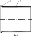
На фиг.2 показан продольный разрез гильзы.Figure 2 shows a longitudinal section of a sleeve.
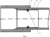
На фиг.3 показан продольный разрез узла сварного соединения трубы с муфтовым элементом, гильза в котором в средней части боковой поверхности снаружи выполнена с кольцевой канавкой, в которой расположено уплотнительное кольцо.Figure 3 shows a longitudinal section of the welded joint of the pipe with the coupling element, the sleeve in which in the middle part of the side surface is made on the outside with an annular groove in which the sealing ring is located.
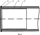
На фиг.4 показан продольный разрез конца трубы, внутрь которой вставлена гильза, при этом на торец трубы одета вставка из термопластичного материала в форме кольца.Figure 4 shows a longitudinal section of the end of the pipe, into which a sleeve is inserted, while an insert of thermoplastic material in the form of a ring is dressed on the end of the pipe.
Узел сварного соединения (фиг.1) трубы 1 с муфтовым элементом 2, являющимся в конкретном частном примере частью соединительной муфты 3 с внутренним радиальным выступом 4, изготовленных из термопластичного материала, дополнительно включает гильзу 5, выполненную тонкостенной в виде отрезка трубы с отогнутым наружу буртиком 6 (фиг.1, 2) по одному из торцов, высота которого не превышает толщину трубы 1, и изготовленную из материала, сохраняющего несущие свойства при температуре, превышающей температуру плавления термопластичного материала трубы 1 и муфтового элемента 2.The welded joint assembly (Fig. 1) of the pipe 1 with the coupling element 2, which in a particular particular example is a part of the coupling 3 with an internal radial protrusion 4 made of thermoplastic material, further includes a
Гильза 5 вставлена внутрь конца трубы 1 до упора буртиком 6 в его торец 7, а труба 1 этим концом вставлена внутрь муфтового элемента 2 с образованием на участке 8 сопряжения части внутренней поверхности муфтового элемента 2 с частью наружной поверхности трубы 1 зоны сварки муфтового элемента 2 с концом трубы 1. Длина гильзы 5 больше длины указанной зоны (8) сварки.The
Как показано на фиг.3 при сварке многослойной трубы 9 (многослойность трубы 9 на фиг.3 не отражена), снаружи в средней части боковой поверхности гильзы 10 выполнена кольцевая канавка 11, в которой расположено уплотнительное кольцо 12. С аналогичной целью, как показано на фиг.4, то есть для предотвращения расслаивания многослойной трубы 13 (многослйность трубы 13 на фиг.4 также не отражена) узел снабжен вставкой 14 из термопластичного материала в форме кольца между торцом трубы 13 и боковой поверхностью внутреннего радиального выступа муфтового элемента (на фиг.1 соответствуют, соответственно, позициям 4, 2), с поверхностями которых вставка 14 сопряжена с образованием дополнительной зоны сварки (на чертежах не показана), которая укрывает буртик 15 гильзы 16.As shown in FIG. 3, when welding a multilayer pipe 9 (the
Как указано выше труба (9, 13) может быть выполнена с промежуточным слоем из алюминиевого сплава или из сополимера этилвинилового спирта. Может быть обеспечена сварка многослойной трубы иной конструкции промежуточных слоев. Сварка обеспечивается, преимущественно, трубы с толщиной в диапазоне 1,5-3 мм и муфтового элемента, изготовленных из полиэтилена повышенной термостойкости. Может быть осуществлена сварка трубы и муфтового элемента, изготовленных из полиэтилена низкого давления или из полипропилена. При использовании вставки 14 она изготавливается из того же материала, что и свариваемые труба и муфтовый элемент. Могут быть сварены труба и муфтовый элемент из иных термопластичных материалов, в том числе в случае, когда подключаемая труба не характеризуется малой толщиной стенки.As indicated above, the pipe (9, 13) can be made with an intermediate layer of aluminum alloy or of a copolymer of ethyl vinyl alcohol. Welding of a multilayer pipe of a different design of intermediate layers can be provided. Welding is mainly provided by pipes with a thickness in the range of 1.5-3 mm and a coupling element made of high temperature resistant polyethylene. Welding can be carried out on pipes and couplings made of low pressure polyethylene or polypropylene. When using the
Гильза (5, 10,16) изготовлена, преимущественно, из латуни, но для ее изготовления могут быть использованы сталь, алюминиевый сплав, иной медный сплав, а также тугоплавкий полимерный конструкционный материал на основе полисульфона (например, полиариленэфир-сульфон, полиалкиленсульфон, полиэфирсульфон). Гильза (5, 10, 16) может, в зависимости от использованного материала, иметь толщину от 0,05 до 1 мм. Может быть использована гильза большей толщины при соответствующем размере свариваемых деталей.The sleeve (5, 10,16) is mainly made of brass, but steel, aluminum alloy, another copper alloy, and also a refractory polysulfone-based structural material (for example, polyarylene ether-sulfone, polyalkylene sulfone, polyethersulfone can be used for its manufacture) ) The sleeve (5, 10, 16) may, depending on the material used, have a thickness of 0.05 to 1 mm. A sleeve of greater thickness can be used with an appropriate size of the parts to be welded.
Технология (способ) соединения сваркой трубы с муфтовым элементом, изготовленных из термопластичного материала, позволяющая получить описанный выше узел соединения, предусматривает проведение следующих операций:The technology (method) of welding a pipe with a coupling element made of a thermoplastic material, which allows to obtain the connection node described above, provides for the following operations:
- установку в привариваемый конец трубы (1, 9, 13) гильзы (5, 10, 16), выполненной как описано выше, до упора буртиком 6 в торец конца трубы (1, 9, 13);- installation in the welded end of the pipe (1, 9, 13) of a sleeve (5, 10, 16), made as described above, until it stops with a
- одновременный нагрев участка наружной поверхности трубы (1, 9, 13) и участка внутренней поверхности муфтового элемента (2) с использованием закрепленных на нагревателе сварочных насадок до расплавления термпопластичного материала на поверхностях указанных участков;- simultaneous heating of the portion of the outer surface of the pipe (1, 9, 13) and the portion of the inner surface of the coupling element (2) using welding nozzles fixed to the heater until the thermoplastic material melts on the surfaces of these sections;
- последующее снятие конца трубы (1, 9, 13) и муфтового элемента (2) со сварочных насадок и их сопряжение друг с другом упомянутыми участками с расплавленным на поверхностях термопластичным материалом путем установки конца трубы (1,9,13) внутрь полости муфтового элемента (2);- the subsequent removal of the pipe end (1, 9, 13) and the coupling element (2) from the welding nozzles and their conjugation with each other by the said sections with thermoplastic material melted on the surfaces by installing the pipe end (1,9,13) inside the cavity of the coupling element (2);
- заключительную выдержку соединенных конца трубы (1, 9, 13) и муфтового элемента (2) до отверждения расплавленного термпопластичного материала с образованием зоны (8) сварки муфтового элемента (2) с концом трубы (1, 9, 13).- final exposure of the connected pipe end (1, 9, 13) and the coupling element (2) until the molten thermoplastic material is solidified with the formation of the welding zone (8) of the coupling element (2) with the pipe end (1, 9, 13).
Перед выполнением этих операций предварительно на трубе (1, 9, 13) может быть сделана отметка глубины введения ее конца внутрь муфтового элемента (2), а при проведении операции установки конца трубы (1, 9, 13) внутрь полости муфтового элемента (2), установку конца трубы (1, 9, 13) осуществляют на глубину, соответствующую указанной предварительно сделанной отметке.Before performing these operations, a depth mark can be made on the pipe (1, 9, 13) before the end of the end is inserted inside the coupling element (2), and during the installation of the pipe end (1, 9, 13) inside the cavity of the coupling element (2) , the installation of the end of the pipe (1, 9, 13) is carried out to a depth corresponding to the indicated previously made mark.
Изобретение не исчерпывается представленным выше примером осуществления. Возможны также иные, лежащие в пределах патентных притязаний, конкретные формы конструктивной реализации изобретения, спроектированные с его использованием и обычных инженерных знаний. Также может быть дополнена дополнительными известными операциями технология соединения сваркой трубы (1, 9, 13) с муфтовым элементом (2).The invention is not limited to the above embodiment. Other, within the scope of patent claims, specific forms of constructive implementation of the invention, designed with its use and ordinary engineering knowledge, are also possible. The technology of joining pipe welding (1, 9, 13) with a coupling element (2) can also be supplemented by additional known operations.
Claims (23)
Priority Applications (4)
| Application Number | Priority Date | Filing Date | Title |
|---|---|---|---|
| RU2012103236/02A RU2503540C2 (en) | 2012-01-31 | 2012-01-31 | Method of welding tube to coupling made of thermoplastic material and welded joint thus made |
| UAA201313749A UA107759C2 (en) | 2012-01-31 | 2012-08-11 | Method and assembly for connecting a pipe to a coupling element |
| PCT/RU2012/000911 WO2013115678A1 (en) | 2012-01-31 | 2012-11-08 | Method and assembly for connecting a pipe to a coupling element |
| EA201301003A EA022823B1 (en) | 2012-01-31 | 2012-11-08 | Method and assembly for connecting a pipe to a coupling element |
Applications Claiming Priority (1)
| Application Number | Priority Date | Filing Date | Title |
|---|---|---|---|
| RU2012103236/02A RU2503540C2 (en) | 2012-01-31 | 2012-01-31 | Method of welding tube to coupling made of thermoplastic material and welded joint thus made |
Publications (2)
| Publication Number | Publication Date |
|---|---|
| RU2012103236A RU2012103236A (en) | 2013-08-10 |
| RU2503540C2 true RU2503540C2 (en) | 2014-01-10 |
Family
ID=48905602
Family Applications (1)
| Application Number | Title | Priority Date | Filing Date |
|---|---|---|---|
| RU2012103236/02A RU2503540C2 (en) | 2012-01-31 | 2012-01-31 | Method of welding tube to coupling made of thermoplastic material and welded joint thus made |
Country Status (4)
| Country | Link |
|---|---|
| EA (1) | EA022823B1 (en) |
| RU (1) | RU2503540C2 (en) |
| UA (1) | UA107759C2 (en) |
| WO (1) | WO2013115678A1 (en) |
Cited By (2)
| Publication number | Priority date | Publication date | Assignee | Title |
|---|---|---|---|---|
| WO2020247168A1 (en) * | 2019-06-07 | 2020-12-10 | Fit-Line, Inc. | Method and apparatus to assemble a high purity liquid distribution system |
| RU2781970C1 (en) * | 2021-12-29 | 2022-10-21 | федеральное государственное автономное образовательное учреждение высшего образования "Казанский (Приволжский) федеральный университет" (ФГАОУ ВО КФУ) | 3d printing plastic bar chemical welding device and method for using it |
Families Citing this family (5)
| Publication number | Priority date | Publication date | Assignee | Title |
|---|---|---|---|---|
| CN105014293B (en) * | 2015-07-17 | 2017-02-01 | 西安航空动力股份有限公司 | Welding lap joint structure and method for thin-wall pipes |
| CN111174004A (en) * | 2020-02-24 | 2020-05-19 | 日丰企业集团有限公司 | Pipe connecting component |
| CN111188953B (en) * | 2020-03-27 | 2024-12-31 | 金品冠科技集团有限公司 | Double-sealed socket-and-spigot compression fitting and assembly method |
| RU2742156C1 (en) * | 2020-04-27 | 2021-02-02 | Общество с ограниченной ответственностью "Геотермал" | Evaporative circuit for ground source heat pump |
| CN112429513B (en) * | 2020-10-26 | 2022-04-22 | 无锡惠玺流体设备科技有限公司 | Adjustable lantern ring device |
Citations (5)
| Publication number | Priority date | Publication date | Assignee | Title |
|---|---|---|---|---|
| GB794833A (en) * | 1955-06-24 | 1958-05-14 | Robert Hudson | Method of and means for jointing tubes |
| DE3422074A1 (en) * | 1984-06-14 | 1986-01-23 | Manfred 6000 Frankfurt Eck | Process for producing non-releasable pipe joints of plastics pipes |
| RU2087785C1 (en) * | 1993-05-12 | 1997-08-20 | Институт проблем транспорта энергоресурсов "ИПТЭР" | Nondetachable pipe joint |
| RU22814U1 (en) * | 2001-07-23 | 2002-04-27 | Закрытое акционерное общество "Полимак" | POLYMER PIPELINE |
| RU2380603C1 (en) * | 2008-09-23 | 2010-01-27 | Общество с ограниченной ответственностью "Дипайп" | Method for connecting multi-layer composite tubes and device for method's implementation |
Family Cites Families (2)
| Publication number | Priority date | Publication date | Assignee | Title |
|---|---|---|---|---|
| WO1997028951A1 (en) * | 1996-02-09 | 1997-08-14 | Heinz Stampfer | Process for the production of weld seams on plastic parts, especially a pipe-welding process, pipeline system with pipe connections produced according to this process as well as the use of an hf generator for the carrying out of this process |
| RU23481U1 (en) * | 2001-09-20 | 2002-06-20 | Закрытое акционерное общество "Полимак" | INTEGRAL CONNECTION OF PIPES FROM REINFORCED THERMOPLAST |
-
2012
- 2012-01-31 RU RU2012103236/02A patent/RU2503540C2/en active IP Right Revival
- 2012-08-11 UA UAA201313749A patent/UA107759C2/en unknown
- 2012-11-08 WO PCT/RU2012/000911 patent/WO2013115678A1/en not_active Ceased
- 2012-11-08 EA EA201301003A patent/EA022823B1/en not_active IP Right Cessation
Patent Citations (5)
| Publication number | Priority date | Publication date | Assignee | Title |
|---|---|---|---|---|
| GB794833A (en) * | 1955-06-24 | 1958-05-14 | Robert Hudson | Method of and means for jointing tubes |
| DE3422074A1 (en) * | 1984-06-14 | 1986-01-23 | Manfred 6000 Frankfurt Eck | Process for producing non-releasable pipe joints of plastics pipes |
| RU2087785C1 (en) * | 1993-05-12 | 1997-08-20 | Институт проблем транспорта энергоресурсов "ИПТЭР" | Nondetachable pipe joint |
| RU22814U1 (en) * | 2001-07-23 | 2002-04-27 | Закрытое акционерное общество "Полимак" | POLYMER PIPELINE |
| RU2380603C1 (en) * | 2008-09-23 | 2010-01-27 | Общество с ограниченной ответственностью "Дипайп" | Method for connecting multi-layer composite tubes and device for method's implementation |
Cited By (7)
| Publication number | Priority date | Publication date | Assignee | Title |
|---|---|---|---|---|
| WO2020247168A1 (en) * | 2019-06-07 | 2020-12-10 | Fit-Line, Inc. | Method and apparatus to assemble a high purity liquid distribution system |
| US11518114B2 (en) | 2019-06-07 | 2022-12-06 | Fit-Line, Inc. | Method and apparatus to assemble a high purity liquid distribution system |
| US12023873B2 (en) | 2019-06-07 | 2024-07-02 | Fit-Line, Inc. | Method and apparatus to assemble a high purity liquid distribution system |
| KR20240172223A (en) * | 2019-06-07 | 2024-12-09 | 피트-라인 인코포레이티드 | Method and apparatus to assemble a high purity liquid distribution system |
| US12337549B2 (en) | 2019-06-07 | 2025-06-24 | Fit-Line, Inc. | Method and apparatus to assemble a high purity liquid distribution system |
| KR102833087B1 (en) | 2019-06-07 | 2025-07-11 | 피트-라인 인코포레이티드 | Method and apparatus to assemble a high purity liquid distribution system |
| RU2781970C1 (en) * | 2021-12-29 | 2022-10-21 | федеральное государственное автономное образовательное учреждение высшего образования "Казанский (Приволжский) федеральный университет" (ФГАОУ ВО КФУ) | 3d printing plastic bar chemical welding device and method for using it |
Also Published As
| Publication number | Publication date |
|---|---|
| EA022823B1 (en) | 2016-03-31 |
| RU2012103236A (en) | 2013-08-10 |
| UA107759C2 (en) | 2015-02-10 |
| WO2013115678A1 (en) | 2013-08-08 |
| EA201301003A1 (en) | 2014-01-30 |
Similar Documents
| Publication | Publication Date | Title |
|---|---|---|
| RU2503540C2 (en) | Method of welding tube to coupling made of thermoplastic material and welded joint thus made | |
| US8398119B2 (en) | Electrofusion fitting | |
| US3701548A (en) | Pipe joint system | |
| US9080702B2 (en) | Method for the highly-thick thermal coating of joints by using electrofusion in pipes used for conducting fluids, made of steel tubes externally coated with polyolefins | |
| US5836621A (en) | Method of and joint for electrofusion coupling of thermoplastic pipes | |
| US5775736A (en) | Plastic pipe fittings | |
| WO1991009247A1 (en) | Fusion pipe joining system and method | |
| JP2013506800A (en) | Pipe joining device | |
| CN103180652B (en) | Couplings for multilayer pipelines, welding devices, joining methods and resulting assemblies thereof | |
| US20130299034A1 (en) | Conveying pipe part of a pneumatic material conveying system and a method for forming a pipe joint | |
| GB2520717A (en) | Techniques for coating pipeline field joints | |
| CN103492779B (en) | modular accessory | |
| RU2380603C1 (en) | Method for connecting multi-layer composite tubes and device for method's implementation | |
| JP2015513653A (en) | Pipe fitting and method for forming a pipe fitting | |
| RU117355U1 (en) | DIFFUSION WELDING CONNECTION ASSEMBLY WITH COUPLING ELEMENT, PRODUCED FROM THERMOPLASTIC MATERIAL, AND A CASE FOR IT | |
| CN103384791B (en) | Pipe joint between two metal tubes and form the method for this pipe joint | |
| WO2023054699A1 (en) | Piping member and method for manufacturing piping member | |
| JPH06341576A (en) | Bayonet joint particularly for metallic pipe for fluid | |
| EP2096347B1 (en) | Method for joining together steel pipes for conveying fluids under pressure | |
| TW201905373A (en) | Resin pipe member, resin pipe member manufacturing method, resin pipe joint, and resin pipe | |
| CN105135133A (en) | Two-dimensional winding wiring unit and wiring method utilizing the same | |
| WO2006027535A1 (en) | Electrofusion coupler | |
| RU85604U1 (en) | DEVICE FOR CONNECTING MULTILAYER COMPOSITE PIPES | |
| CN221592092U (en) | Pipe joint for PSP steel-plastic composite pipe | |
| KR200389186Y1 (en) | Joint for pipe |
Legal Events
| Date | Code | Title | Description |
|---|---|---|---|
| MM4A | The patent is invalid due to non-payment of fees |
Effective date: 20190201 |
|
| PD4A | Correction of name of patent owner | ||
| NF4A | Reinstatement of patent |
Effective date: 20200204 |
|
| MM4A | The patent is invalid due to non-payment of fees |
Effective date: 20210201 |
|
| NF4A | Reinstatement of patent |
Effective date: 20210907 |