RU2502582C2 - Cutter with clamp - Google Patents
Cutter with clamp Download PDFInfo
- Publication number
- RU2502582C2 RU2502582C2 RU2011135731/02A RU2011135731A RU2502582C2 RU 2502582 C2 RU2502582 C2 RU 2502582C2 RU 2011135731/02 A RU2011135731/02 A RU 2011135731/02A RU 2011135731 A RU2011135731 A RU 2011135731A RU 2502582 C2 RU2502582 C2 RU 2502582C2
- Authority
- RU
- Russia
- Prior art keywords
- hole
- protrusion
- locking
- axis
- orifice
- Prior art date
Links
Images


Classifications
-
- B—PERFORMING OPERATIONS; TRANSPORTING
- B23—MACHINE TOOLS; METAL-WORKING NOT OTHERWISE PROVIDED FOR
- B23B—TURNING; BORING
- B23B31/00—Chucks; Expansion mandrels; Adaptations thereof for remote control
- B23B31/02—Chucks
- B23B31/10—Chucks characterised by the retaining or gripping devices or their immediate operating means
- B23B31/113—Retention by bayonet connection
-
- B—PERFORMING OPERATIONS; TRANSPORTING
- B23—MACHINE TOOLS; METAL-WORKING NOT OTHERWISE PROVIDED FOR
- B23B—TURNING; BORING
- B23B27/00—Tools for turning or boring machines; Tools of a similar kind in general; Accessories therefor
- B23B27/14—Cutting tools of which the bits or tips or cutting inserts are of special material
- B23B27/16—Cutting tools of which the bits or tips or cutting inserts are of special material with exchangeable cutting bits or cutting inserts, e.g. able to be clamped
-
- B—PERFORMING OPERATIONS; TRANSPORTING
- B23—MACHINE TOOLS; METAL-WORKING NOT OTHERWISE PROVIDED FOR
- B23B—TURNING; BORING
- B23B31/00—Chucks; Expansion mandrels; Adaptations thereof for remote control
- B23B31/02—Chucks
- B23B31/10—Chucks characterised by the retaining or gripping devices or their immediate operating means
- B23B31/117—Retention by friction only, e.g. using springs, resilient sleeves, tapers
-
- F—MECHANICAL ENGINEERING; LIGHTING; HEATING; WEAPONS; BLASTING
- F16—ENGINEERING ELEMENTS AND UNITS; GENERAL MEASURES FOR PRODUCING AND MAINTAINING EFFECTIVE FUNCTIONING OF MACHINES OR INSTALLATIONS; THERMAL INSULATION IN GENERAL
- F16D—COUPLINGS FOR TRANSMITTING ROTATION; CLUTCHES; BRAKES
- F16D1/00—Couplings for rigidly connecting two coaxial shafts or other movable machine elements
- F16D1/06—Couplings for rigidly connecting two coaxial shafts or other movable machine elements for attachment of a member on a shaft or on a shaft-end
- F16D1/08—Couplings for rigidly connecting two coaxial shafts or other movable machine elements for attachment of a member on a shaft or on a shaft-end with clamping hub; with hub and longitudinal key
- F16D1/0817—Couplings for rigidly connecting two coaxial shafts or other movable machine elements for attachment of a member on a shaft or on a shaft-end with clamping hub; with hub and longitudinal key with radial clamping due to rotation along an eccentric surface, e.g. arcuate wedging elements
-
- B—PERFORMING OPERATIONS; TRANSPORTING
- B23—MACHINE TOOLS; METAL-WORKING NOT OTHERWISE PROVIDED FOR
- B23B—TURNING; BORING
- B23B2231/00—Details of chucks, toolholder shanks or tool shanks
- B23B2231/02—Features of shanks of tools not relating to the operation performed by the tool
- B23B2231/0204—Connection of shanks to working elements of tools
-
- B—PERFORMING OPERATIONS; TRANSPORTING
- B23—MACHINE TOOLS; METAL-WORKING NOT OTHERWISE PROVIDED FOR
- B23B—TURNING; BORING
- B23B2251/00—Details of tools for drilling machines
- B23B2251/02—Connections between shanks and removable cutting heads
-
- B—PERFORMING OPERATIONS; TRANSPORTING
- B23—MACHINE TOOLS; METAL-WORKING NOT OTHERWISE PROVIDED FOR
- B23B—TURNING; BORING
- B23B2270/00—Details of turning, boring or drilling machines, processes or tools not otherwise provided for
- B23B2270/06—Use of elastic deformation
-
- Y—GENERAL TAGGING OF NEW TECHNOLOGICAL DEVELOPMENTS; GENERAL TAGGING OF CROSS-SECTIONAL TECHNOLOGIES SPANNING OVER SEVERAL SECTIONS OF THE IPC; TECHNICAL SUBJECTS COVERED BY FORMER USPC CROSS-REFERENCE ART COLLECTIONS [XRACs] AND DIGESTS
- Y10—TECHNICAL SUBJECTS COVERED BY FORMER USPC
- Y10T—TECHNICAL SUBJECTS COVERED BY FORMER US CLASSIFICATION
- Y10T407/00—Cutters, for shaping
- Y10T407/19—Rotary cutting tool
- Y10T407/1906—Rotary cutting tool including holder [i.e., head] having seat for inserted tool
- Y10T407/1908—Face or end mill
- Y10T407/1912—Tool adjustable relative to holder
-
- Y—GENERAL TAGGING OF NEW TECHNOLOGICAL DEVELOPMENTS; GENERAL TAGGING OF CROSS-SECTIONAL TECHNOLOGIES SPANNING OVER SEVERAL SECTIONS OF THE IPC; TECHNICAL SUBJECTS COVERED BY FORMER USPC CROSS-REFERENCE ART COLLECTIONS [XRACs] AND DIGESTS
- Y10—TECHNICAL SUBJECTS COVERED BY FORMER USPC
- Y10T—TECHNICAL SUBJECTS COVERED BY FORMER US CLASSIFICATION
- Y10T407/00—Cutters, for shaping
- Y10T407/22—Cutters, for shaping including holder having seat for inserted tool
- Y10T407/227—Cutters, for shaping including holder having seat for inserted tool with separate means to fasten tool seat to holder
-
- Y—GENERAL TAGGING OF NEW TECHNOLOGICAL DEVELOPMENTS; GENERAL TAGGING OF CROSS-SECTIONAL TECHNOLOGIES SPANNING OVER SEVERAL SECTIONS OF THE IPC; TECHNICAL SUBJECTS COVERED BY FORMER USPC CROSS-REFERENCE ART COLLECTIONS [XRACs] AND DIGESTS
- Y10—TECHNICAL SUBJECTS COVERED BY FORMER USPC
- Y10T—TECHNICAL SUBJECTS COVERED BY FORMER US CLASSIFICATION
- Y10T407/00—Cutters, for shaping
- Y10T407/28—Miscellaneous
Landscapes
- Engineering & Computer Science (AREA)
- Mechanical Engineering (AREA)
- General Engineering & Computer Science (AREA)
- Cutting Tools, Boring Holders, And Turrets (AREA)
- Clamps And Clips (AREA)
- Connection Of Plates (AREA)
Abstract
Description
Область техники, к которой относится изобретениеFIELD OF THE INVENTION
Изобретение относится к области режущих инструментов, имеющих зажимные механизмы, а именно зажимные механизмы между державкой и хвостовиком.The invention relates to the field of cutting tools having clamping mechanisms, namely, clamping mechanisms between the holder and the shank.
Уровень техникиState of the art
Использование зажимных механизмов широко распространено в отрасли режущих инструментов. Существует множество типов зажимных механизмов для широкого круга применений.The use of clamping mechanisms is widespread in the cutting tool industry. There are many types of clamping mechanisms for a wide range of applications.
В некоторых режущих инструментах режущая пластина, обычно выполненная из твердого сплава или другого твердого материала, удерживается в державке для режущих пластин, обычно выполненной из стали. При большом вылете, когда отношение длины к диаметру режущего инструмента относительно велико, предпочтительно использовать твердосплавный хвостовик, для того чтобы увеличить общую жесткость режущего инструмента. Такое использование твердосплавного хвостовика, однако, также предпочтительно в режущих инструментах, имеющих более короткий вылет. В таком типе режущих инструментов режущая пластина или множество режущих пластин удерживаются внутри державки для режущих пластин, выполненной из стали, а державка для режущих пластин удерживается твердосплавным хвостовиком.In some cutting tools, a cutting insert, usually made of a hard alloy or other hard material, is held in a holder for cutting inserts, usually made of steel. For large overhangs, when the ratio of length to diameter of the cutting tool is relatively large, it is preferable to use a carbide shank in order to increase the overall rigidity of the cutting tool. Such use of a carbide shank, however, is also preferred in cutting tools having a shorter overhang. In this type of cutting tool, a cutting insert or a plurality of cutting inserts are held inside a steel tool holder, and a tool holder is held by a carbide shank.
Существует несколько типов механизмов для прикрепления державки для режущих пластин к твердосплавному хвостовику. В некоторых механизмах, державка для режущих пластин отводится назад посредством зажимного болта, который продолжается вдоль сквозного отверстия в хвостовике. Зажатие державки для режущих пластин к хвостовику происходит затягиванием зажимного болта с задней стороны хвостовика. Недостатком такого зажатия является то, что для того чтобы заменить державку для режущих пластин, необходимо убрать хвостовик из его положения в станке, для того чтобы иметь возможность ослабить зажимной болт. Такая задача, конечно, трудоемка и требует много времени.There are several types of mechanisms for attaching a toolholder for inserts to a carbide shank. In some mechanisms, the insert holder is retracted by a clamp bolt that extends along the through hole in the shank. Clamping the holder for the cutting inserts to the shank occurs by tightening the clamping bolt on the rear side of the shank. The disadvantage of this clamping is that in order to replace the holder for the cutting inserts, it is necessary to remove the shank from its position in the machine in order to be able to loosen the clamping bolt. Such a task, of course, is laborious and time consuming.
В других механизмах затягивание державки для режущих пластин выполняется зажимным болтом, который проходит через переднюю сторону или боковую сторону державки для режущих пластин. Зажимной болт может зацепляться с державкой для режущих пластин или хвостовиком. Такое зажатие требует выполнения дополнительных резьб, что является относительно затратным в твердосплавном хвостовике. Более того, дополнительные отверстия в державке для режущих пластин снижают способность плавного отведения стружек, которые образуются во время обработки.In other mechanisms, the insert holder is tightened by a clamping bolt that extends through the front or side of the insert holder. The clamping bolt may engage with the holder for the inserts or the shank. Such clamping requires additional threads, which is relatively expensive in a carbide shank. Moreover, additional holes in the holder for cutting inserts reduce the ability to smoothly remove chips that form during processing.
В других режущих инструментах задний конец стальной державки для режущих пластин припаян к переднему концу твердосплавного хвостовика. Недостатком такого соединения является относительно большое расстояние между твердосплавным хвостовиком и точкой прикладывания усилия к режущей пластине во время обработки. Когда усилия, приложенные к режущей пластине, в основном радиальные, такое относительно большое расстояние снижает преимущество наличия жесткого хвостовика и обеспечивает развитие деформации и вибрации в державке для режущих пластин.In other cutting tools, the rear end of the steel toolholder for the cutting inserts is soldered to the front end of the carbide shank. The disadvantage of this connection is the relatively large distance between the carbide shank and the point of application of force to the cutting insert during processing. When the forces applied to the cutting insert are substantially radial, such a relatively large distance reduces the advantage of having a rigid shank and allows deformation and vibration to develop in the holder for the cutting inserts.
В патенте США № 6394465, выданном Guy, описано зажимное устройство (1, 25, 35) для съемного зажатия вставляемого элемента (9, 27, 38) хвостовиком. Зажимное устройство содержит зажимной элемент, имеющий установочное отверстие (11, 26, 40), образованное объединением участка (19A, 31A, 41A) входного отверстия и участка (19В, 31В, 41В) захватывающего отверстия, для свободного скользящего введения в хвостовик и извлечения из него в отношении участка входного отверстия и его зажатия зажимной поверхностью участка захватывающего отверстия при его принудительном смещении в него из участка входного отверстия. Причем участки входного и захватывающего отверстий имеют продольные оси (20A, 20В; 32А, 32В; 43А, 43B), отстоящие по меньшей мере вдоль их участка.US Pat. No. 6,394,465 to Guy describes a clamping device (1, 25, 35) for releasably clamping an insert member (9, 27, 38) with a shank. The clamping device comprises a clamping element having a mounting hole (11, 26, 40) formed by combining the portion of the inlet opening (19A, 31A, 41A) and the gripping hole section (19B, 31B, 41B) for free sliding insertion into the shank and extraction from him in relation to the plot of the inlet and its clamping the clamping surface of the plot of the exciting hole when it is forced to shift into it from the plot of the inlet. Moreover, the sections of the inlet and the capture holes have longitudinal axes (20A, 20B; 32A, 32B; 43A, 43B) spaced at least along their section.
Зажимное устройство согласно указанному патенту обеспечивает надежное зажатие хвостовика участком захватывающего отверстия. Однако надежное зажатие поддерживается посредством внешнего усилия, прикладываемого дополнительным устройством, таким как гильза, зажимной винт или гаечный ключ (17, 29, 35). Внешнее усилие обеспечивает то, что хвостовик остается прижатым к участку захватывающего отверстия. Без дополнительного устройства, зажимное устройство согласно указанному патенту не может работать само по себе, поскольку, любое внешнее усилие, приложенное на захваченный хвостовик, в направлении, перпендикулярном продольному направлению хвостовика, вытянет хвостовик из участка захватывающего отверстия.The clamping device according to the aforementioned patent provides reliable clamping of the shank by a portion of the gripping hole. However, reliable clamping is maintained by external force exerted by an additional device, such as a sleeve, a clamping screw or a wrench (17, 29, 35). An external force ensures that the shank remains pressed against a portion of the pick hole. Without an additional device, the clamping device according to the aforementioned patent cannot work on its own, because any external force applied to the gripped shank in the direction perpendicular to the longitudinal direction of the shank will pull the shank out of the area of the gripping hole.
Задачей настоящего изобретения является создание зажимного механизма, который значительно ослабляет или устраняет вышеуказанные недостатки.An object of the present invention is to provide a clamping mechanism that significantly reduces or eliminates the above disadvantages.
Дополнительной задачей настоящего изобретения является создание зажимного механизма, который остается надежно зафиксированным без необходимости в каком-либо дополнительном устройстве.An additional objective of the present invention is to provide a clamping mechanism that remains securely locked without the need for any additional device.
Еще одной задачей настоящего изобретения является создание легкого и простого в использовании зажимного механизма.Another objective of the present invention is to provide an easy and easy to use clamping mechanism.
Еще одной дополнительной задачей настоящего изобретения является создание зажимного механизма с удлиненной опорой охватывающей части охватываемой частью, а, в частности, твердосплавным хвостовиком.Another additional objective of the present invention is to provide a clamping mechanism with an elongated support of the female part of the male part, and, in particular, carbide shank.
Еще одной дополнительной задачей настоящего изобретения является создание режущего инструмента, имеющего зажимной механизм, который остается надежно зафиксированным без необходимости в каком-либо дополнительном устройстве. Такой режущий инструмент обеспечивает легкий и простой в использовании зажимной механизм и преимущество наличия дополнительной опоры режущей головке удлиненной опорой хвостовика. Эти преимущества особенно применимы при использовании твердосплавного хвостовика, который поддерживает стальную державку для режущих пластин.Another additional objective of the present invention is to provide a cutting tool having a clamping mechanism, which remains securely fixed without the need for any additional device. Such a cutting tool provides an easy and easy to use clamping mechanism and the advantage of having additional support for the cutting head with an elongated shaft support. These advantages are especially applicable when using a carbide shank that supports a steel holder for cutting inserts.
Раскрытие изобретенияDisclosure of invention
Согласно настоящему изобретению предлагается зажимной механизм, содержащий охватываемую часть и охватывающую часть;The present invention provides a clamping mechanism comprising a male part and a female part;
причем охватываемая часть содержит:moreover, the covered part contains:
корпус, имеющий переднюю поверхность хвостовика в его передней части;a housing having a front surface of the shank in its front part;
фиксирующий выступ, продолжающийся вперед от передней поверхности хвостовика, причем фиксирующий выступ имеет вращательную симметрию относительно оси фиксирующего выступа, диаметр фиксирующего выступа и радиус фиксирующего выступа в заданном первом сечении, перпендикулярном оси фиксирующего выступа, и переднюю поверхность фиксирующего выступа в его передней части; иa locking protrusion extending forward from the front surface of the shank, the locking protrusion having rotational symmetry about the axis of the locking protrusion, the diameter of the locking protrusion and the radius of the locking protrusion in a predetermined first section perpendicular to the axis of the locking protrusion, and the front surface of the locking protrusion in its front part; and
выравнивающий выступ, продолжающийся вперед относительно передней поверхности фиксирующего выступа, причем выравнивающий выступ имеет вращательную симметрию относительно оси выравнивающего выступа и диаметр выравнивающего выступа в заданном втором сечении;a leveling protrusion extending forward relative to the front surface of the locking protrusion, the leveling protrusion having rotational symmetry about the axis of the leveling protrusion and the diameter of the leveling protrusion in a predetermined second section;
причем охватывающая часть содержит:moreover, the covering part contains:
охватывающий корпус, имеющий заднюю поверхность державки в его задней части;enclosing a housing having a rear surface of the holder in its rear part;
фиксирующее отверстие, имеющее передний конец фиксирующего отверстия в его передней части, продолжающийся вперед от задней поверхности державки, причем фиксирующее отверстие содержит:a locking hole having a front end of the locking hole in its front portion extending forward from the rear surface of the holder, the locking hole comprising:
участок установочного отверстия, имеющий радиус установочного отверстия в заданном третьем сечении и ось установочного отверстия, иa mounting hole portion having a mounting hole radius in a predetermined third section and a mounting hole axis, and
участок захватывающего отверстия, имеющий радиус захватывающего отверстия в заданном третьем сечении и ось захватывающего отверстия, причем ось захватывающего отверстия отстоит от оси установочного отверстия на ненулевое первое расстояние; иa picking hole portion having a picking hole radius in a predetermined third section and an picking hole axis, wherein the picking hole axis is non-zero first distance from the axis of the mounting hole; and
выравнивающее отверстие, продолжающееся вперед относительно переднего конца фиксирующего отверстия, причем выравнивающее отверстие имеет ось выравнивающего отверстия, которая отстоит на второе расстояние от оси захватывающего отверстия, и диаметр выравнивающего отверстия в заданном четвертом сечении; при этом:a leveling hole extending forward relative to the front end of the fixing hole, wherein the leveling hole has an axis of the leveling hole that is a second distance from the axis of the picking hole, and a diameter of the leveling hole in a predetermined fourth section; wherein:
в незажатом положении зажимного механизма радиус захватывающего отверстия меньше радиуса фиксирующего выступа;in the unclamped position of the clamping mechanism, the radius of the gripping hole is less than the radius of the locking protrusion;
осевое расположение заданного первого сечения совпадает с осевым расположением заданного третьего сечения в зажатом положении зажимного механизма; иthe axial location of the specified first section coincides with the axial location of the specified third section in the clamped position of the clamping mechanism; and
осевое расположение заданного второго сечения совпадает с осевым расположением заданного четвертого сечения в зажатом положении зажимного механизма.the axial location of the specified second section coincides with the axial location of the specified fourth section in the clamped position of the clamping mechanism.
Предпочтительно, в зажатом положении зажимного механизма фиксирующий выступ примыкает к участку захватывающего отверстия по его захватывающей поверхности вдоль захватывающего углового продолжения, которое составляет более 180°, а выравнивающий выступ примыкает к участку выравнивающего отверстия.Preferably, in the clamped position of the clamping mechanism, the locking protrusion is adjacent to the portion of the gripping hole along its gripping surface along the gripping angular extension, which is more than 180 °, and the leveling protrusion is adjacent to the portion of the leveling hole.
Обычно захватывающее угловое продолжение составляет более 180° и менее 190°.Typically, a spectacular angular extension of more than 180 ° and less than 190 °.
При сборке зажимного механизма на первом сборочном этапе охватывающий элемент подводится в осевом направлении к охватываемому элементу, так что выравнивающее отверстие свободно направляется в осевом направлении над выравнивающим выступом, и участок установочного отверстия свободно направляется в осевом направлении над фиксирующим выступом;When assembling the clamping mechanism in the first assembly step, the female member is axially guided to the male member so that the alignment hole is freely axially directed above the leveling protrusion and the mounting hole portion is axially freely guided by the locking protrusion;
на втором сборочном этапе участок установочного отверстия поворачивается относительно оси выравнивающего отверстия, так что участок захватывающего отверстия принудительно располагается на фиксирующем выступе.in the second assembly step, the mounting hole portion is rotated relative to the axis of the leveling hole, so that the gripping hole portion is forcibly located on the locking protrusion.
Предпочтительно, участок захватывающего отверстия охватывающей части остается зафиксированным на фиксирующем выступе охватываемой части без необходимости в каком-либо дополнительном устройстве.Preferably, the portion of the gripping hole of the female part remains fixed on the locking protrusion of the male part without the need for any additional device.
При необходимости в зажатом положении задняя поверхность державки примыкает к передней поверхности хвостовика.If necessary, in the clamped position, the back surface of the holder adjoins the front surface of the shank.
В одном варианте осуществления фиксирующий выступ сужается назад под первым углом выступа относительно оси фиксирующего выступа;In one embodiment, the locking protrusion tapers backward at a first angle of the protrusion with respect to the axis of the locking protrusion;
фиксирующее отверстие сужается назад под первым углом отверстия относительно оси захватывающего отверстия; иthe fixing hole tapers backward at a first angle of the hole relative to the axis of the picking hole; and
первый угол отверстия может быть аналогичен первому углу выступа или быть немного больше него.the first corner of the hole may be similar to the first corner of the protrusion or be slightly larger.
Обычно первый угол выступа составляет от 1° до 20°.Usually the first angle of the protrusion is from 1 ° to 20 °.
При необходимости в зажатом положении задняя поверхность державки примыкает к передней поверхности хвостовика.If necessary, in the clamped position, the back surface of the holder adjoins the front surface of the shank.
В одном варианте осуществления выравнивающий выступ сужается вперед под вторым углом выступа;In one embodiment, the alignment protrusion tapers forward at a second angle of the protrusion;
выравнивающее отверстие сужается вперед под вторым углом отверстия; иthe leveling hole tapers forward at a second angle of the hole; and
второй угол отверстия может быть аналогичен второму углу выступа или немного больше него.the second corner of the hole may be similar to the second corner of the protrusion or slightly larger.
Обычно, второй угол выступа составляет от 2° до 30°.Typically, the second protrusion angle is from 2 ° to 30 °.
В одном варианте выполнения в зажатом положении задняя поверхность державки не примыкает к передней поверхности хвостовика.In one embodiment, in the clamped position, the back surface of the holder does not abut against the front surface of the shank.
Обычно, первое расстояние составляет от 0,2 мм до 2 мм.Usually, the first distance is from 0.2 mm to 2 mm.
Также обычно, фиксирующий выступ имеет длину фиксирующего выступа;Also typically, the locking protrusion has a length of the locking protrusion;
выравнивающий выступ имеет длину выравнивающего выступа; иthe alignment protrusion has a length of the alignment protrusion; and
длина выравнивающего выступа больше длины фиксирующего выступа.the length of the leveling protrusion is greater than the length of the locking protrusion.
В другом варианте настоящее изобретение относится к режущему инструменту, имеющему зажимной механизм, содержащий охватываемый элемент и охватывающий элемент, которые образуют два компонента. Режущий инструмент может дополнительно содержать режущую пластину, и выравнивающий выступ может продолжаться вперед до точки, которая находится в общем радиально внутри относительно режущей пластины.In another embodiment, the present invention relates to a cutting tool having a clamping mechanism comprising a male member and a female member that form two components. The cutting tool may further comprise a cutting insert, and the alignment protrusion may extend forward to a point that is generally radially inward with respect to the cutting insert.
Краткое описание чертежейBrief Description of the Drawings
Чтобы лучше понять настоящее изобретение и показать, как оно может быть осуществлено на практике, будет сделана ссылка на сопроводительные чертежи, на которых:In order to better understand the present invention and show how it can be put into practice, reference will be made to the accompanying drawings, in which:
фиг.1 - вид в перспективе режущего инструмента, зажатого зажимным механизмом согласно настоящему изобретению;figure 1 is a perspective view of a cutting tool clamped by a clamping mechanism according to the present invention;
фиг.2 - вид в перспективе с пространственным разнесением элементов режущего инструмента по фиг.1;figure 2 is a perspective view with a spatial exploded elements of the cutting tool of figure 1;
фиг.3 - вид сзади в перспективе с пространственным разнесением элементов режущего инструмента по фиг.1;figure 3 is a rear view in perspective with a spatial exploded elements of the cutting tool of figure 1;
фиг.4 - вид спереди хвостовика;4 is a front view of the shank;
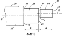
фиг.5 - местный вид сверху хвостовика;5 is a local top view of the shank;
фиг.6 - вид сзади державки для режущих пластин;6 is a rear view of the holder for cutting inserts;
фиг.7 - вид сбоку державки для режущих пластин в сечении вдоль линии VII-VII на фиг.6;Fig.7 is a side view of a holder for cutting inserts in section along the line VII-VII in Fig.6;
фиг.8 - вид державки для режущих пластин в сечении вдоль линии VIII-VIII на фиг.7;Fig.8 is a view of the holder for the cutting inserts in section along the line VIII-VIII in Fig.7;
фиг.9 - продольный вид собранного хвостовика и державки для режущих пластин в сечении по линии IX-IX на фиг.10;Fig.9 is a longitudinal view of the assembled shank and holder for cutting inserts in section along the line IX-IX in figure 10;
фиг.10 - вид собранного хвостовика и державки для режущих пластин в сечении по линии X-X на фиг.9;figure 10 is a view of the assembled shank and holder for cutting inserts in section along the line X-X in figure 9;
фиг.11 - продольный вид в сечении собранного хвостовика и державки для режущих пластин согласно другому варианту осуществления настоящего изобретения; и11 is a longitudinal sectional view of an assembled shank and holder for cutting inserts according to another embodiment of the present invention; and
фиг.12 - продольный вид в сечении собранного хвостовика и державки для режущих пластин согласно другому варианту выполнения настоящего изобретения.12 is a longitudinal sectional view of an assembled shank and holder for cutting inserts according to another embodiment of the present invention.
Подробное описание изобретенияDETAILED DESCRIPTION OF THE INVENTION
Со ссылкой сначала на фиг.1-5. На фиг.1-3 показан режущий инструмент 10, зажатый зажимным механизмом 12 согласно настоящему изобретению. Режущий инструмент 10 имеет ось A режущего инструмента и содержит хвостовик 14 и державку 16 для режущих пластин, которая разъемно присоединена к хвостовику 14. В описании описана охватываемая часть зажимного механизма в виде хвостовика 14 и охватывающая часть зажимного механизма в виде державки 16 для режущих пластин. Однако следует понимать, что в общем, охватываемая часть является просто первым компонентом, а охватывающая часть является вторым компонентом.Referring first to FIGS. 1-5. 1-3 show a
Хвостовик 14 согласно настоящему изобретению выполнен из твердого сплава. Однако настоящее изобретение не ограничено только хвостовиками, выполненными из твердого сплава, и могут быть в равной степени использованы другие материалы хвостовиков, такие как закаленная сталь, инструментальная сталь или т.п.The
Державка 16 для режущих пластин согласно настоящему изобретению выполнена из инструментальной стали. Однако настоящее изобретение не ограничено только державками для режущих пластин, выполненными из инструментальной стали, и могут быть в равной степени использованы другие материалы, тем не менее, предпочтительно, чтобы материал державки для режущих пластин был мягче материала хвостовика.The
Державка 16 для режущих пластин снабжена вторым корпусным элементом 17 и гнездом 18 под режущую пластину в переднем участке 20 державки 16 для режущих пластин. Режущая пластина 22 надежно удерживается в гнезде 18 под режущую пластину посредством зажимного винта 24. Углубление 26 для стружки продолжается назад от режущей пластины 22, для того чтобы достаточно удалять стружки, образуемые во время обработки. Охлаждающее отверстие 27 державки для режущих пластин выполнено в стружковой впадине 26, для того чтобы подавать охлаждающую жидкость к режущей пластине 22 во время обработки.The cutting
Гнездо 18 под режущую пластину, а также тип фиксации режущей пластины 22 в гнезде 18 под режущую пластину не являются существенными признаками настоящего изобретения и, следовательно, не будут описаны ниже. Более того, отсутствует необходимость в фиксировании режущей пластины 22 в державке 16 для режущих пластин посредством зажимного винта 24, и могут быть в равной степени использованы другие способы фиксации. Например, режущая пластина 22 может быть зафиксирована посредством зажима. В качестве альтернативы, режущая пластина может быть припаяна к гнезду под режущую пластину или может быть выполнена заодно целое с державкой для режущих пластин, чтобы иметь единую цельную конструкцию. В таком случае вся державка фактически является сменной вставкой.The
Как видно из фиг.2, хвостовик 14, имеющий ось B хвостовика, имеет удлиненный корпус 28 хвостовика, имеющий диаметр D1 корпуса хвостовика. Во время обработки корпус 28 хвостовика фиксируется посредством переходника или непосредственно режущего станка (не показан). Согласно одному варианту осуществления настоящего изобретения, корпус 28 хвостовика является цилиндрическим. В таком случае корпус 28 хвостовика может быть выполнен с выемкой 30 хвостовика, для того чтобы облегчить прикрепление корпуса 28 хвостовика к режущему станку. Следует понимать, что возможны другие формы корпуса 28 хвостовика. Например, корпус 28 хвостовика может быть коническим, квадратным, шестиугольным или любой другой требуемой формы.As can be seen from FIG. 2, a
Передний участок 32 корпуса 28 хвостовика выполнен с кольцевой передней поверхностью 34 хвостовика. Передняя поверхность 34 хвостовика может быть плоской и перпендикулярной оси B хвостовика.The
Фиксирующий выступ 36 продолжается вперед от передней поверхности 34 хвостовика. Фиксирующий выступ 36 является цилиндрическим, имеющим диаметр D2 фиксирующего выступа, и имеет ось C фиксирующего выступа, которая совпадает с осью B хвостовика. Диаметр D2 фиксирующего выступа, имеющего радиус r2 фиксирующего выступа, меньше диаметра D1 корпуса хвостовика. Фиксирующий выступ 36 продолжается вперед от передней поверхности 34 хвостовика на длину L1 фиксирующего выступа и заканчивается передней поверхностью 38 фиксирующего выступа. Передняя поверхность 38 фиксирующего выступа может быть плоской и перпендикулярной оси C фиксирующего выступа.The locking
Выравнивающий выступ 40 продолжается вперед от передней поверхности 38 фиксирующего выступа. Выравнивающий выступ 40 является цилиндрическим, имеющим диаметр D3 выравнивающего выступа, и имеет ось E выравнивающего выступа. Как видно из фиг.4 и 5, диаметр D3 выравнивающего выступа намного меньше диаметра D2 фиксирующего выступа.The leveling
Ось E выравнивающего выступа может быть параллельна оси C фиксирующего выступа. Однако ось E выравнивающего выступа не совпадает с осью C фиксирующего выступа и отстоит от нее на расстояние L. Выравнивающий выступ 40 продолжается вперед от передней поверхности 38 фиксирующего выступа на длину L2 выравнивающего выступа и заканчивается передней поверхностью 42 выравнивающего выступа. В одном варианте осуществления, как показано на фиг.5, длина L2 выравнивающего выступа больше длины L1 фиксирующего выступа. Однако в других вариантах осуществления длина L2 выравнивающего выступа может быть равна или меньше длины L1 фиксирующего выступа.The axis E of the alignment protrusion may be parallel to the axis C of the locking protrusion. However, the axis E of the alignment protrusion does not coincide with the axis C of the locking protrusion and is spaced apart by a distance L. The
В одном варианте осуществления выравнивающий выступ 40 имеет армированный участок 44, смежный передней поверхности 38 фиксирующего выступа. Аналогично фиксирующий выступ 36 может быть выполнен со вторым армированным участком 46, смежным передней поверхности 34 хвостовика. В некоторых вариантах осуществления хвостовик 14 дополнительно выполнен с охлаждающим отверстием 48 хвостовика, которое продолжается от задней поверхности 50 хвостовика 14 к передней поверхности 38 фиксирующего выступа.In one embodiment, the leveling
Далее будет сделана ссылка на фиг.6-8, на которых показана державка 16 для режущих пластин. Как показано, державка 16 для режущих пластин содержит фиксирующее отверстие 52, которое открывается к заднему концу державки 16 для режущих пластин. Задний конец державки имеет заднюю поверхность 54 державки, которая может быть плоской и перпендикулярна оси G державки.Next, reference will be made to Fig.6-8, which shows the
Фиксирующее отверстие 52 содержит два участка отверстия, а именно, участок 56 захватывающего отверстия и участок 58 установочного отверстия. Как лучшим образом видно на фиг.6, участок 56 захватывающего отверстия соединен с участком 58 установочного отверстия. Участок 56 захватывающего отверстия имеет ось H захватывающего отверстия, которая совпадает с осью G державки, и радиус R1 захватывающего отверстия. Периферийная поверхность участка 56 захватывающего отверстия является захватывающей поверхностью 60. Фиксирующее отверстие 52 продолжается вперед от задней поверхности 54 державки на длину L3 фиксирующего отверстия и заканчивается на переднем конце 62 фиксирующего отверстия. Передний конец 62 фиксирующего отверстия может быть плоским и перпендикулярным оси G державки.The locking
Радиус R1 захватывающего отверстия немного меньше радиуса r2 фиксирующего выступа, то есть R1<r2. Обычно, радиус R1 захватывающего отверстия меньше радиуса r2 фиксирующего выступа на от около 0,001 мм до 0,05 мм. Согласно одному варианту осуществления, радиус R1 установочного отверстия больше радиуса r2 фиксирующего выступа на 0,005 мм.The radius R1 of the gripping hole is slightly smaller than the radius r2 of the locking protrusion, that is, R1 <r2. Typically, the radius R1 of the capture hole is less than the radius r2 of the locking protrusion by about 0.001 mm to 0.05 mm. According to one embodiment, the radius R1 of the mounting hole is greater than the radius r2 of the locking protrusion by 0.005 mm.
Участок 56 захватывающего отверстия имеет захватывающее угловое продолжение α, которое составляет более 180°. Обычно, захватывающее угловое продолжение α составляет более 180° и менее 190°. Согласно одному варианту осуществления, захватывающее угловое продолжение α составляет 184° с отклонением в ±0,5°.The capturing
Участок 58 установочного отверстия имеет ось K установочного отверстия, которая может быть параллельна оси G державки, и, радиус R2 установочного отверстия. Радиус R2 установочного отверстия больше радиуса r2 фиксирующего выступа и больше радиуса R1 захватывающего отверстия, то есть R2>r2>R1. Обычно, радиус R2 установочного отверстия больше радиуса r2 фиксирующего выступа на от 0,01 мм до 1 мм. Согласно одному варианту осуществления, радиус R2 установочного отверстия больше радиуса r2 фиксирующего выступа на 0,1 мм.The mounting
Как видно на фиг.6, ось K установочного отверстия отстоит на ненулевое первое расстояние M от оси H захватывающего отверстия. Линия, соединяющая ось K установочного отверстия и ось H захватывающего отверстия, может образовывать биссектрису захватывающего углового продолжения α, если смотреть на державку 16 для режущих пластин сзади. Первое расстояние M обычно составляет от 0,2 мм до 2 мм. Однако, большая или меньшая величина первого расстояния M может быть выбрана в зависимости от размера режущего инструмента 10. Согласно одному варианту осуществления, первое расстояние M составляет около 0,9 мм.As can be seen in FIG. 6, the axis K of the mounting hole is spaced a nonzero first distance M from the axis H of the picking hole. The line connecting the axis K of the mounting hole and the axis H of the gripping hole can form a bisector of the gripping angular extension α when looking at the
Выравнивающее отверстие 64 продолжается вперед от фиксирующего отверстия 52 на длину L4 выравнивающего отверстия и заканчивается передним концом 66 выравнивающего отверстия. Как видно на фиг.7, длина L4 выравнивающего отверстия больше длины L3 фиксирующего отверстия. Однако в других вариантах осуществления длина L4 выравнивающего отверстия может быть равна или меньше длины L3 фиксирующего отверстия.The
Выравнивающее отверстие 64 имеет ось N выравнивающего отверстия и диаметр D4 выравнивающего отверстия, имеющего радиус R3 выравнивающего отверстия. Диаметр D4 выравнивающего отверстия немного больше диаметра D3 выравнивающего выступа, для того чтобы обеспечить свободную установку выравнивающего выступа 40 в выравнивающее отверстие 64. В некоторых вариантах осуществления диаметр D4 выравнивающего отверстия больше диаметра D3 выравнивающего выступа на от 0,005 мм до 0,5 мм.The leveling
Ось N выравнивающего отверстия может быть параллельна оси H захватывающего отверстия. Как показано на фиг.6, ось N выравнивающего отверстия не совпадает с осью H захватывающего отверстия и отстоит от нее на второе расстояние Q.The N axis of the alignment hole may be parallel to the H axis of the pick hole. As shown in FIG. 6, the N axis of the alignment hole does not coincide with the H axis of the capture hole and is spaced a second distance Q from it.
В одном варианте осуществления выравнивающее отверстие 64, в его задней части, выполнено с расширением 68 отверстия. Расширение 68 отверстия служит для двух целей. Первая: оно облегчает установку выравнивающего выступа 40 в выравнивающее отверстие 64. Вторая: оно зацепляется с армированным участком 44 между фиксирующим выступом 36 и выравнивающим выступом 40.In one embodiment, the
Обычно державка 16 для режущих пластин может быть выполнена с по меньшей мере одной выемкой 70 державки, для того чтобы облегчить использование гаечного ключа (не показан) для окончательного затягивания державки 16 для режущих пластин на хвостовике 14.Typically, the
Способ использования зажимного механизма 12, а именно установка державки 16 для режущих пластин на хвостовик 14, будет описан ниже.A method of using the
Сначала державку 16 для режущих пластин выравнивают в осевом направлении с хвостовиком 14, так что выравнивающий выступ 40 вставляется в выравнивающее отверстие 64, и ось E выравнивающего выступа по существу совпадает с осью N выравнивающего отверстия. Термин «по существу совпадает» означает то, что ось E выравнивающего выступа может совпадать с осью N выравнивающего отверстия в пределах производственных допусков между выравнивающим выступом 40 и выравнивающим отверстием 64.First, the cutting
Затем фиксирующий выступ 36 выравнивают в осевом направлении с участком 58 установочного отверстия.Then, the locking
На следующем этапе державку 16 для режущих пластин перемещают прямолинейно в осевом направлении к хвостовику 14 до тех пор, пока задняя поверхность 54 державки не упрется в переднюю поверхность 34 хвостовика. Следует понимать, что до этого этапа - отсутствует напряжение между державкой 16 для режущих пластин и хвостовиком 14.In the next step, the cutting
Затем державку 16 для режущих пластин эксцентрично поворачивают относительно хвостовика 14, вокруг оси E выравнивающего выступа, в фиксирующем направлении державки 16 для режущих пластин, так что выравнивающее отверстие 64 удерживает выравнивающий выступ 40 в качестве оси, опираясь на его часть, и фиксирующий выступ 36 принудительно вставляется в участок 56 захватывающего отверстия. Поскольку радиус R1 захватывающего отверстия немного меньше радиуса r2 фиксирующего выступа, державка 16 для режущих пластин должна принудительно поворачиваться, например, гаечным ключом, зацепленным с выемкой 70 державки, так что участок 56 захватывающего отверстия немного увеличивается вследствие упругости державки 16 для режущих пластин. Державку 16 для режущих пластин эксцентрично поворачивают до тех пор, пока фиксирующий выступ 36 полностью не упрется в захватывающую поверхность 60 участка 56 захватывающего отверстия, таким образом, образуя периферийную посадку с натягом, в которой периферийная внешняя поверхность 36 фиксирующего выступа примыкает к периферийной внутренней поверхности участка 56 захватывающего отверстия.Then, the cutting
На данном этапе относительное вращение между державкой 16 для режущих пластин и хвостовиком 14 прекращается, и затягивающий снаружи гаечный ключ может быть убран, поскольку выравнивающий выступ упирается в участок выравнивающего отверстия, и фиксирующий выступ 36 независимо и надежно удерживается участком 56 захватывающего отверстия, поскольку захватывающее угловое продолжение α участка 56 захватывающего отверстия составляет более 180°.At this stage, the relative rotation between the
Таким образом, режущий инструмент 10 обеспечивает зажимной механизм 12, который остается надежно зафиксированным без необходимости в каком-либо дополнительном устройстве, и, таким образом, два элемента 14, 16 прикреплены друг к другу без удерживающего винта или другого механизма, прикрепляющего державку 16 для режущих пластин к фиксирующему выступу 36 или выравнивающему выступу 40. Более того, как легко понятно специалисту в данной области техники, зажимной механизм 12 легко и просто использовать, поскольку требуется только очень малое относительное перемещение, чтобы обеспечить периферийную посадку с натягом, обычно около 2°, между державкой 16 для режущих пластин и хвостовиком 14, чтобы перейти из расфиксированного положения в зафиксированное положение и обратно.Thus, the cutting
Как показано на фиг.3 и 6, на которых показан вид державки 16 для режущих пластин сзади, для того чтобы перевести державку 16 для режущих пластин в зафиксированное положение относительно хвостовика 14, державку 16 для режущих пластин эксцентрично поворачивают в направлении против часовой стрелки, как показано фиксирующим направлением 72. Соответственно, для того чтобы перевести державку 16 для режущих пластин в расфиксированное положение относительно хвостовика 14, державку 16 для режущих пластин эксцентрично поворачивают в направлении часовой стрелки, как показано расфиксирующим направлением 74.As shown in FIGS. 3 and 6, a rear view of the cutting
Когда режущий инструмент 10 используется в процессе резания, тангенциальные усилия FT, действующие на режущую пластину 22 во время обработки, стремятся удерживать державку 16 для режущих пластин прижатой к хвостовику 14, таким образом, способствуя усилению затягивания зажимного механизма 12. Специалисту в данной области техники понятно, что также радиальные усилия FR и осевые усилия FA, которые действуют на режущую пластину 22 во время обработки, стремятся удерживать державку 16 для режущих пластин прижатой к хвостовику 14.When the
Простое и легкое зажатие режущей головки 16 с хвостовиком 14 обеспечивает легкую замену державки 16 для режущих пластин, при этом хвостовик 14 остается зажатым в режущем станке. Таким образом, могут быть сэкономлены время и силы во время замены державки 16 для режущих пластин.Simple and easy clamping of the cutting
Для того чтобы извлечь державку 16 для режущих пластин из хвостовика 14, последний просто эксцентрично поворачивают, посредством гаечного ключа, относительно хвостовика 14 в расфиксирующем направлении 74. Это вызывает вращение выравнивающего выступа 40, который служит в качестве оси, внутри выравнивающего отверстия 64, и вызывает расцепление фиксирующего выступа 36 с участком 56 захватывающего отверстия и свободную остановку внутри участка 58 установочного отверстия. На данном этапе отсутствует напряжение между державкой 16 для режущих пластин и хвостовиком 14, и державка 16 для режущих пластин может быть свободно вытянута прямолинейно вперед и извлечена из хвостовика 14.In order to remove the
Более того, поскольку в зафиксированном положении фиксирующий выступ 36 надежно примыкает внутри участка 56 захватывающего отверстия, а выравнивающий выступ примыкает к участку выравнивающего отверстия, положение державки 16 для режущих пластин, и, таким образом, положение активной режущей кромки режущей пластины 22 хорошо определено в пределах допусков. Следовательно, когда хвостовик 14 остается зажатым в режущем станке и заменяется только державка 16 для режущих пластин, новая державка 16 для режущих пластин будет зажата на хвостовике 14 с тем же расположением и направлением ориентации режущей пластины 22, и обеспечивается хорошая стабильность позиционирования. Таким образом, достигается быстрая и экономичная замена державки 16 для режущих пластин, а длительное регулирование режущего края новой режущей пластины 22 предпочтительно исключается.Moreover, since in the locked position, the locking
Поскольку только малое угловое перемещение требуется, для того чтобы перевести державку 16 для режущих пластин из расфиксированного положения в зафиксированное положение, режущий инструмент 10, использующий зажимной механизм 12 согласно настоящему изобретению, особенно полезен в труднодоступных местах, в которых пространство, доступное для снятия державки 16 для режущих пластин, в некоторой степени ограничено.Since only a small angular movement is required in order to move the
Поскольку заменить державку 16 для режущих пластин легко, предпочтительно использовать несколько типов державок для режущих пластин при необходимости, то есть после использования данной державки для режущих пластин она может быть легко заменена другой державкой для режущих пластин, которая может иметь другое назначение и удерживать другой тип режущей пластины в ней. Таким образом, может быть экономически выгодным выполнить несколько так называемых «заготовок» державок для режущих пластин, имеющих одинаковый зажимной участок для зацепления с одним хвостовиком 14. Затем передний участок каждого из державок для режущих пластин может быть легко обработан, чтобы соответствовать требованиям определенного назначения.Since it is easy to replace the cutting
Как показано на фиг.7, передний конец 66 выравнивающего отверстия 64 продолжается вперед почти до переднего участка 20 державки 16 для режущих пластин. В некоторых вариантах осуществления, как показано, например на фиг.7 и 9, выравнивающее отверстие 64 открывается к разгрузочному отверстию 76 гнезда под режущую пластину, которое является частью гнезда 18 под режущую пластину. Этот признак в действительности означает, что в зафиксированном положении державки 16 для режущих пластин на хвостовике 14 выравнивающий выступ 40 продолжается вперед до точки, или почти до точки, которая находится радиально внутри относительно режущей пластины 22.As shown in FIG. 7, the
Этот признак также относится к вариантам осуществления, показанным на фиг.11 и 12. А именно, даже если выравнивающее отверстие не открывается к разгрузочному отверстию 76 гнезда под режущую пластину, тем не менее, выравнивающий выступ продолжается вперед до точки, или почти до точки, которая находится радиально внутри относительно режущей пластины 22.This feature also applies to the embodiments shown in FIGS. 11 and 12. Namely, even if the alignment hole does not open to the discharge opening 76 of the insert insert, however, the alignment protrusion extends forward to a point, or almost to a point, which is radially inside relative to the
Поскольку материал хвостовика 14 обычно намного тверже материала державки 16 для режущих пластин, например, твердый сплав по сравнению с инструментальной сталью, поддержка выравнивающего отверстия 64 выравнивающим выступом 40 по существу увеличивает общую жесткость державки 16 для режущих пластин. Таким образом, настоящее изобретение обеспечивает зажимной механизм с удлиненной опорой хвостовика. Удлиненная опора хвостовика особенно предпочтительна, когда хвостовик выполнен из твердого сплава.Since the material of the
Таким образом, режущий инструмент 10 имеет преимущество в двух аспектах. Во-первых, конструкция державки 16 для режущих пластин из инструментальной стали делает ее относительно дешевой, легкой в производстве и легкозаменяемой. Во-вторых, удлиненная опора твердосплавного хвостовика обеспечивает режущий инструмент 10 высокой жесткостью, аналогичной жесткости, которую он мог бы иметь, если бы был весь выполнен из твердого сплава. Таким образом, увеличением жесткости режущего инструмента 10 он менее подвержен изгибу и колебаниям и, следовательно, может работать с высокой точностью.Thus, the cutting
На фиг.9 показан продольный вид в сечении собранного хвостовика 14 и державки 16 для режущих пластин, зажатой зажимным механизмом 12 согласно настоящему изобретению. Как показано, в зажатом положении фиксирующий выступ 36 удерживается внутри фиксирующего отверстия 52, выравнивающий выступ 40 удерживается внутри выравнивающего отверстия 64, а задняя поверхность 54 державки примыкает к передней поверхности 34 хвостовика.Figure 9 shows a longitudinal sectional view of an assembled
На фиг.10 показано сечение фиксирующего выступа 36 и фиксирующего отверстия 52, когда державка 16 для режущих пластин установлена на хвостовик 14.Figure 10 shows a cross section of the locking
Как показано на фиг.10, в зажатом положении фиксирующего выступа 36 он зажат участком 56 захватывающего отверстия и полностью примыкает к захватывающей поверхности 60 вдоль захватывающего углового продолжения α, которое составляет более 180°. В этом положении участок 58 установочного отверстия не примыкает. Как уже отмечалось, выравнивающий выступ примыкает к участку выравнивающего отверстия (не показано на этом чертеже), и державка 16 для режущих пластин остается зажатой в хвостовике 14 без какого-либо дополнительного устройства или усилия. Следовательно, для того чтобы перевести державку 16 для режущих пластин в незажатое положение относительно хвостовика 14, должен быть использован гаечный ключ, для того чтобы эксцентрично повернуть державку 16 для режущих пластин в расфиксирующем направлении 74 относительно хвостовика 14.As shown in FIG. 10, in the clamped position of the locking
На фиг.11 показан продольный вид в сечении собранного хвостовика и державки для режущих пластин, зажатой согласно другому варианту осуществления зажимного механизма согласно настоящему изобретению. В этом варианте осуществления одинаковые ссылочные позиции, которые использовались в отношении варианта осуществления, показанного на фиг.1-10, обозначены аналогичными ссылочными позициями, но увеличенными на 100.11 shows a longitudinal sectional view of an assembled shank and holder for cutting inserts clamped according to another embodiment of a clamping mechanism according to the present invention. In this embodiment, the same reference numerals that were used with respect to the embodiment shown in FIGS. 1-10 are denoted by the same reference numerals, but increased by 100.
В этом варианте осуществления державка 116 для режущих пластин зажата к хвостовику 114. Хвостовик 114 содержит переднюю поверхность 134 хвостовика. Фиксирующий выступ 136 продолжается вперед от передней поверхности 134 хвостовика. Выравнивающий выступ 140 продолжается вперед от фиксирующего выступа 136. Фиксирующий выступ 136 сужается назад и скошен под первым углом β выступа относительно оси B хвостовика. Первый угол β выступа может составлять от 1° до 20°. Согласно конкретному варианту осуществления настоящего изобретения, первый угол β выступа составляет 10°.In this embodiment, the
Державка 116 для режущих пластин имеет заднюю поверхность 154 державки. Фиксирующее отверстие 152 продолжается вперед от задней поверхности 154 державки. Фиксирующее отверстие 152 сужается назад и скошено под первым углом γ отверстия относительно оси G державки. Первый угол γ отверстия может быть равен первому углу β выступа или немного больше его. Выравнивающее отверстие 164 продолжается вперед от фиксирующего отверстия 152.The cutting
Конструкция фиксирующего отверстия 152, за исключением его сужения назад под первым углом γ отверстия, аналогична конструкции фиксирующего отверстия 52, описанной со ссылкой на вариант осуществления, показанный на фиг.1-10. Таким образом, фиксирующее отверстие 152 содержит участок захватывающего отверстия и участок установочного отверстия, который в сечении аналогичен сечению, показанному на фиг.10.The design of the
Фиксация державки 116 для режущих пластин на хвостовике 114 выполняется аналогично тому, как описано со ссылкой на вариант осуществления, показанный на фиг.1-10. Однако, поскольку фиксирующий выступ 136 и фиксирующее отверстие 152 сужаются назад, державка 116 для режущих пластин жестко зафиксирована на хвостовике 116. Таким образом, даже если державка 116 для режущих пластин подвержена большим осевым усилиям, которые стремятся вытянуть державку 116 для режущих пластин из ее гнезда во время обработки, державка 116 для режущих пластин будет сопротивляться отсоединению от хвостовика 114.The fixing of the cutting
На фиг.12 показан продольный вид в сечении собранного хвостовика и державки для режущих пластин, зажатой согласно еще одному варианту осуществления зажимного механизма согласно настоящему изобретению. В этом варианте осуществления одинаковые ссылочные позиции, которые использовались в отношении варианта осуществления, показанного на фиг.1-10, обозначены аналогичными ссылочными позициями, но увеличенными на 200.12 is a longitudinal sectional view of an assembled shank and holder for cutting inserts clamped according to yet another embodiment of a clamping mechanism according to the present invention. In this embodiment, the same reference numerals that were used with respect to the embodiment shown in FIGS. 1-10 are denoted by the same reference numerals, but increased by 200.
В этом варианте осуществления державка 216 для режущих пластин зажата на хвостовике 214. Хвостовик 214 содержит переднюю поверхность 234 хвостовика. Фиксирующий выступ 236 продолжается вперед от передней поверхности 234 хвостовика. Фиксирующий выступ 236 сужается назад и скошен под первым углом β выступа относительно оси B хвостовика, аналогично первому углу β выступа, как описано в отношении фиг.11.In this embodiment, the
Выравнивающий выступ 240 продолжается вперед от фиксирующего выступа 236. Выравнивающий выступ 240 сужается вперед и скошен под вторым углом δ выступа относительно оси E выравнивающего выступа. Второй угол δ выступа может составлять от 2° до 30°. Согласно конкретному варианту осуществления настоящего изобретения, второй угол δ выступа составляет 10°.The leveling
Державка 216 для режущих пластин имеет заднюю поверхность 254 державки. Фиксирующее отверстие 252 продолжается вперед от задней поверхности 254 державки. Фиксирующее отверстие 252 сужается назад и скошено под первым углом γ отверстия относительно оси G державки, аналогично первому углу γ отверстия, как описано в отношении фиг.11. Выравнивающее отверстие 264 продолжается вперед от фиксирующего отверстия 252. Выравнивающее отверстие 264 сужается вперед и скошено под углом вторым φ отверстия. Второй угол φ отверстия может быть равен второму углу δ выступа или может быть немного больше него.The
Конструкция фиксирующего отверстия 252, за исключением его сужения назад под первым углом γ отверстия, аналогична конструкции фиксирующего отверстия 52, описанной ранее со ссылкой на вариант осуществления, показанный на фиг.1-10. Таким образом, фиксирующее отверстие 252 содержит участок захватывающего отверстия и участок установочного отверстия, который в сечении аналогичен сечению, показанному на фиг.10.The design of the locking hole 252, except for narrowing it backward at a first angle γ of the hole, is similar to the design of the locking
Для того чтобы перевести державку 216 для режущих пластин в зажатое положение с хвостовиком 214, державку 216 для режущих пластин выравнивают в осевом направлении с хвостовиком 214. Затем державку 216 для режущих пластин перемещают в осевом направлении к хвостовику 214 до тех пор, пока выравнивающее отверстие 264 не упрется в выравнивающий выступ 240. В этом положении, а также в конечном зажатом положении задняя поверхность 254 державки отстоит от передней поверхности 234 хвостовика.In order to move the
Фиксация державки 216 для режущих пластин на хвостовике 214 выполняется аналогично тому, как описано со ссылкой на вариант осуществления, показанный на фиг.1-10. Однако, поскольку фиксирующий выступ 236 и фиксирующее отверстие 252 сужаются назад, державка 216 для режущих пластин жестко зафиксирована на хвостовике 216. Таким образом, даже если державка 216 для режущих пластин подвержена большим осевым усилиям, которые стремятся вытянуть державку 216 для режущих пластин из ее гнезда во время обработки, расцепление державки 216 для режущих пластин будет предотвращено. Более того, поскольку выравнивающее отверстие 264 надежно упирается в выравнивающий выступ 240 вследствие их взаимного сужения вперед, дополнительная поддержка будет приложена к режущей пластине во время обработки, поскольку даже небольшой зазор между выравнивающим выступом 240 и выравнивающим отверстием 264 исключен.The fixing of the
Хотя настоящее изобретение было описано с некоторой степенью конкретности, следует понимать, что могут быть выполнены различные изменения и дополнения, не выходящие за рамки сущности или объема изобретения, как ниже заявлено.Although the present invention has been described with some degree of specificity, it should be understood that various changes and additions can be made without departing from the essence or scope of the invention, as stated below.
Например, фиксирующее направление 72 и расфиксирующее направление 74 необязательно должны быть такими, как показано на чертежах, и они могут быть противоположно ориентированы для противоположно направленной фиксации державки для режущих пластин относительно хвостовика.For example, the locking
Зажимной механизм 12 необязательно должен использоваться только для зажатия державки для режущих пластин, составляющей охватывающую часть, на хвостовике, составляющем охватываемую часть. Таким образом, зажимной механизм 12 может быть использован для зажатия вместе двух охватываемой и охватывающей частей переходника, продолжающихся стержней и подобного, причем охватываемая и охватывающая части содержат ответные компоненты.The
Как показано, фиксирующий выступ, а также фиксирующее отверстие могут быть в общем цилиндрическими или коническими. Аналогично, выравнивающий выступ, а также выравнивающее отверстие могут быть в общем цилиндрическими или коническими. То есть они все имеют вращательную симметрию относительно заданной продольной оси.As shown, the locking protrusion as well as the locking hole may be generally cylindrical or conical. Likewise, the alignment protrusion as well as the alignment hole may be generally cylindrical or conical. That is, they all have rotational symmetry about a given longitudinal axis.
Следовательно, для того чтобы описать диаметральную взаимосвязь между соответствующим выступом хвостовика и соответствующим ему отверстием державки в случае, когда они являются коническими, взаимосвязь измеряется относительно заданного сечения, которое перпендикулярно соответствующей продольной оси, и заданное сечение выступа хвостовика совпадает с соответствующим сечением отверстия державки в зажатом положении зажимного механизма.Therefore, in order to describe the diametrical relationship between the corresponding protrusion of the shank and the corresponding hole of the holder in the case when they are conical, the relationship is measured relative to a given section that is perpendicular to the longitudinal axis, and a given section of the protrusion of the shank coincides with the corresponding section of the hole of the holder position of the clamping mechanism.
Claims (18)
при этом охватываемая часть содержит:
первый корпусной компонент (28), имеющий ось (B) первого компонента, определяющую направление спереди назад, и переднюю поверхность (34) первого компонента,
фиксирующий выступ (36, 136, 236), продолжающийся вперед относительно передней поверхности (34) первого компонента, причем фиксирующий выступ имеет радиус (r2) фиксирующего выступа, ось (C) фиксирующего выступа и переднюю поверхность (38) фиксирующего выступа, и
выравнивающий выступ (40, 140, 240), продолжающийся вперед относительно передней поверхности (38) фиксирующего выступа, причем выравнивающий выступ имеет ось (E) выравнивающего выступа, которая отстоит от оси (C) фиксирующего выступа на ненулевое расстояние, и переднюю поверхность (42) выравнивающего выступа,
при этом охватывающая часть содержит:
второй корпусной компонент (17), имеющий ось (G) второго компонента, определяющую направление спереди назад, и заднюю поверхность (54, 154, 254) второго компонента,
фиксирующее отверстие (52, 152, 252), продолжающееся вперед относительно задней поверхности (54, 154, 254) второго компонента и имеющее передний конец (62) фиксирующего отверстия, причем фиксирующее отверстие содержит:
участок (58) установочного отверстия, имеющий радиус (R2) установочного отверстия и ось (K) установочного отверстия,
участок (56)захватывающего отверстия, имеющий радиус (R1) захватывающего отверстия и ось (H) захватывающего отверстия, которая отстоит от оси (K) установочного отверстия на ненулевое первое расстояние (M), причем участок захватывающего отверстия соединен с участком установочного отверстия, и
выравнивающее отверстие (64, 164, 264), продолжающееся вперед относительно переднего конца (62) фиксирующего отверстия, причем выравнивающее отверстие имеет ось (N) выравнивающего отверстия, которая отстоит от оси (H) захватывающего отверстия на ненулевое второе расстояние (Q),
при этом в незажатом положении:
выравнивающий выступ занимает выравнивающее отверстие,
фиксирующий выступ занимает участок установочного отверстия фиксирующего отверстия,
не образуется посадка с натягом между фиксирующим выступом и фиксирующим отверстием, и
охватываемая часть может быть извлечена из охватывающей части, а в зажатом положении:
выравнивающий выступ примыкает к участку выравнивающего отверстия, фиксирующий выступ занимает участок захватывающего отверстия фиксирующего отверстия,
фиксирующий выступ примыкает к захватывающей поверхности (60) участка захватывающего отверстия,
образуется посадка с натягом между фиксирующим выступом и фиксирующим отверстием, а
участок (56) захватывающего отверстия без использования дополнительного средства остается зафиксированным на фиксирующем выступе (36).1. The clamping mechanism (12) containing the male part (14, 114, 214) and the female part (16, 116, 216), made with the possibility of regulation between the unclamped position and the clamped position relative to each other,
while the covered part contains:
a first housing component (28) having an axis (B) of the first component defining a front to back direction and a front surface (34) of the first component,
a locking protrusion (36, 136, 236) extending forward relative to the front surface (34) of the first component, the locking protrusion having a radius (r2) of the locking protrusion, the axis (C) of the locking protrusion and the front surface (38) of the locking protrusion, and
the alignment protrusion (40, 140, 240) extending forward relative to the front surface (38) of the fixation protrusion, the alignment protrusion has an axis (E) of the alignment protrusion, which is non-zero from the axis (C) of the fixation protrusion, and the front surface (42 ) leveling protrusion,
while the covering part contains:
a second housing component (17) having an axis (G) of a second component defining a front to back direction and a rear surface (54, 154, 254) of the second component,
a fixing hole (52, 152, 252) extending forward relative to the rear surface (54, 154, 254) of the second component and having a front end (62) of the fixing hole, the fixing hole comprising:
a mounting hole portion (58) having a mounting hole radius (R2) and a mounting hole axis (K),
a gripping hole portion (56) having a gripping hole radius (R1) and a gripping hole axis (H) that is non-zero a first distance (M) from the mounting hole axis (K), wherein the gripping hole portion is connected to the mounting hole portion, and
a leveling hole (64, 164, 264) extending forward relative to the front end (62) of the fixing hole, the leveling hole having an axis (N) of the leveling hole which is non-zero second distance (Q) from the axis of the pickup hole (Q),
while in the unclamped position:
the leveling protrusion occupies the leveling hole,
the locking protrusion occupies a portion of the mounting hole of the fixing hole,
an interference fit is not formed between the locking protrusion and the locking hole, and
the male part can be removed from the female part, and in the clamped position:
the alignment protrusion is adjacent to the portion of the alignment hole, the fixation protrusion occupies the portion of the capture hole of the fixation hole,
the locking protrusion adjoins the gripping surface (60) of the gripping hole portion,
an interference fit is formed between the locking protrusion and the locking hole, and
the portion (56) of the capture hole without using additional means remains fixed on the locking protrusion (36).
фиксирующее отверстие (152, 252) сужается назад под первым углом (γ) отверстия, и
первый угол (γ) отверстия равен первому углу (β) выступа.6. The mechanism according to claim 1, in which the locking protrusion (136, 236) tapers back at a first angle (β) of the protrusion,
the fixing hole (152, 252) tapers back at the first angle (γ) of the hole, and
the first angle (γ) of the hole is equal to the first angle (β) of the protrusion.
выравнивающее отверстие (264) сужается вперед под вторым углом (φ) отверстия, и
второй угол (φ) отверстия равен второму углу (δ) выступа.9. The mechanism of claim 8, in which the alignment protrusion (240) tapers forward at a second angle (δ) of the protrusion,
the alignment hole (264) tapers forward at a second angle (φ) of the hole, and
the second angle (φ) of the hole is equal to the second angle (δ) of the protrusion.
выравнивающий выступ (40) имеет длину (L2) выравнивающего выступа; и
длина (L2) выравнивающего выступа больше длины (L1) фиксирующего выступа.13. The mechanism according to claim 1, in which the locking protrusion (36) has a length (L1) of the locking protrusion,
the alignment protrusion (40) has a length (L2) of the alignment protrusion; and
the length (L2) of the alignment protrusion is greater than the length (L1) of the locking protrusion.
Applications Claiming Priority (3)
| Application Number | Priority Date | Filing Date | Title |
|---|---|---|---|
| IL196764A IL196764A (en) | 2009-01-28 | 2009-01-28 | Clamping mechanism |
| IL196764 | 2009-01-28 | ||
| PCT/IL2010/000029 WO2010086846A1 (en) | 2009-01-28 | 2010-01-13 | Cutting tool having a clamping mechanism |
Publications (2)
| Publication Number | Publication Date |
|---|---|
| RU2011135731A RU2011135731A (en) | 2013-03-10 |
| RU2502582C2 true RU2502582C2 (en) | 2013-12-27 |
Family
ID=42113441
Family Applications (1)
| Application Number | Title | Priority Date | Filing Date |
|---|---|---|---|
| RU2011135731/02A RU2502582C2 (en) | 2009-01-28 | 2010-01-13 | Cutter with clamp |
Country Status (13)
| Country | Link |
|---|---|
| US (1) | US8434973B2 (en) |
| EP (1) | EP2391471B1 (en) |
| JP (1) | JP5555259B2 (en) |
| KR (1) | KR101343221B1 (en) |
| CN (1) | CN102300659B (en) |
| BR (1) | BRPI1007548A2 (en) |
| CA (1) | CA2752432C (en) |
| ES (1) | ES2402888T3 (en) |
| IL (1) | IL196764A (en) |
| PL (1) | PL2391471T3 (en) |
| PT (1) | PT2391471E (en) |
| RU (1) | RU2502582C2 (en) |
| WO (1) | WO2010086846A1 (en) |
Families Citing this family (10)
| Publication number | Priority date | Publication date | Assignee | Title |
|---|---|---|---|---|
| ES2390171T3 (en) | 2008-07-21 | 2012-11-07 | Becton, Dickinson And Company | Density phase separation device |
| US9333445B2 (en) | 2008-07-21 | 2016-05-10 | Becton, Dickinson And Company | Density phase separation device |
| IL210893A (en) * | 2011-01-26 | 2015-01-29 | Iscar Ltd | Cutting tool |
| CN103702788B (en) * | 2011-08-02 | 2016-11-16 | 伊斯卡有限公司 | Cutting element and for cutting tip being remained to clamping device thereon |
| JP2014524357A (en) * | 2011-08-02 | 2014-09-22 | イスカーリミテッド | Modular cutting tool holder and its clamping mechanism |
| JP5825358B2 (en) * | 2011-12-15 | 2015-12-02 | 株式会社タンガロイ | Cutting insert clamping mechanism, cutting tool, cutting insert and clamp member |
| CN102794361A (en) * | 2012-08-03 | 2012-11-28 | 芜湖长胜机械制造有限公司 | Side molding knife block of forming die of automobile parts |
| JP7102283B2 (en) * | 2018-08-22 | 2022-07-19 | 京セラ株式会社 | Manufacturing method for holders, cutting tools and cutting products |
| DE102020114431A1 (en) * | 2020-05-29 | 2021-03-18 | Schaeffler Technologies AG & Co. KG | Tool holder and method for turning a workpiece |
| CN113953565B (en) * | 2021-11-11 | 2023-06-27 | 株洲钻石切削刀具股份有限公司 | Drilling tool |
Citations (4)
| Publication number | Priority date | Publication date | Assignee | Title |
|---|---|---|---|---|
| SU1085689A1 (en) * | 1979-07-25 | 1984-04-15 | Sharapov Vladimir | Adapter |
| RU2007636C1 (en) * | 1991-05-05 | 1994-02-15 | Сибирский металлургический институт им.Серго Орджоникидзе | Detachable joint |
| RU2053053C1 (en) * | 1992-01-27 | 1996-01-27 | Сибирский металлургический институт | Cutting tool |
| US6394465B1 (en) * | 1997-08-28 | 2002-05-28 | E.T.M. Precision Tools Manufacturing, Ltd. | Clamping device |
Family Cites Families (15)
| Publication number | Priority date | Publication date | Assignee | Title |
|---|---|---|---|---|
| US22681A (en) * | 1859-01-18 | stkwakt | ||
| US1824509A (en) * | 1929-08-30 | 1931-09-22 | Ira J Snader | Rotary tool coupling |
| US2473351A (en) * | 1947-12-24 | 1949-06-14 | Thompson Luke | Locking device for telescopic connections |
| US2910315A (en) * | 1957-04-22 | 1959-10-27 | Oliver L Stevens | Locking means |
| US3953138A (en) * | 1975-01-06 | 1976-04-27 | Seaway Supply Company | One-way twist lock for telescopic tubes |
| DE3016944A1 (en) * | 1980-05-02 | 1981-11-05 | Robert Bosch Gmbh, 7000 Stuttgart | Positive detachable connection e.g. between shaft and hub - comprises eccentric boss on end of one component fitting in mating recess in other |
| DE3205088A1 (en) * | 1982-02-12 | 1983-08-18 | Keil Werkzeugfabrik, Karl Eischeid GmbH, 5250 Engelskirchen | Drive coupling for tools |
| US4832556A (en) * | 1982-10-12 | 1989-05-23 | Dowling Arthur J | Coupling apparatus |
| US4597699A (en) * | 1984-08-27 | 1986-07-01 | Erickson Tool Company | Quick-connect mechanism |
| SE467449B (en) * | 1988-05-06 | 1992-07-20 | Seco Tools Ab | DEVICE FOR CONNECTING A HANDLE AND A SHEET AND A SCREW UNIT THEREOF, WHICH TENSION ELEMENTS IN THE SHEET COULD COOPERATE WITH A RADIALLY RELEASABLE LOCKER |
| JPH0550306A (en) * | 1991-03-13 | 1993-03-02 | Mitsubishi Materials Corp | Cutting tool |
| JPH079212A (en) * | 1993-06-24 | 1995-01-13 | Daishowa Seiki Co Ltd | Coupling |
| JPH10217042A (en) * | 1997-02-07 | 1998-08-18 | Olympus Optical Co Ltd | Retaining mechanism for metal member and luminous optical element retaining mechanism |
| GB2322593B (en) * | 1997-02-28 | 1999-05-05 | Bosch Gmbh Robert | Clamping mechanism for a power tool |
| JP2000176724A (en) * | 1998-12-09 | 2000-06-27 | Mitsubishi Materials Corp | Fitting type cutting tool |
-
2009
- 2009-01-28 IL IL196764A patent/IL196764A/en not_active IP Right Cessation
-
2010
- 2010-01-13 JP JP2011547052A patent/JP5555259B2/en not_active Expired - Fee Related
- 2010-01-13 RU RU2011135731/02A patent/RU2502582C2/en not_active IP Right Cessation
- 2010-01-13 EP EP10705441A patent/EP2391471B1/en not_active Not-in-force
- 2010-01-13 BR BRPI1007548A patent/BRPI1007548A2/en not_active IP Right Cessation
- 2010-01-13 PL PL10705441T patent/PL2391471T3/en unknown
- 2010-01-13 PT PT107054413T patent/PT2391471E/en unknown
- 2010-01-13 CA CA2752432A patent/CA2752432C/en not_active Expired - Fee Related
- 2010-01-13 CN CN201080005648.8A patent/CN102300659B/en not_active Expired - Fee Related
- 2010-01-13 WO PCT/IL2010/000029 patent/WO2010086846A1/en active Application Filing
- 2010-01-13 ES ES10705441T patent/ES2402888T3/en active Active
- 2010-01-13 KR KR1020117017574A patent/KR101343221B1/en active IP Right Grant
- 2010-01-15 US US12/688,486 patent/US8434973B2/en not_active Expired - Fee Related
Patent Citations (4)
| Publication number | Priority date | Publication date | Assignee | Title |
|---|---|---|---|---|
| SU1085689A1 (en) * | 1979-07-25 | 1984-04-15 | Sharapov Vladimir | Adapter |
| RU2007636C1 (en) * | 1991-05-05 | 1994-02-15 | Сибирский металлургический институт им.Серго Орджоникидзе | Detachable joint |
| RU2053053C1 (en) * | 1992-01-27 | 1996-01-27 | Сибирский металлургический институт | Cutting tool |
| US6394465B1 (en) * | 1997-08-28 | 2002-05-28 | E.T.M. Precision Tools Manufacturing, Ltd. | Clamping device |
Also Published As
| Publication number | Publication date |
|---|---|
| BRPI1007548A2 (en) | 2018-09-11 |
| EP2391471A1 (en) | 2011-12-07 |
| CA2752432A1 (en) | 2010-08-05 |
| CN102300659A (en) | 2011-12-28 |
| CA2752432C (en) | 2014-03-18 |
| PL2391471T3 (en) | 2013-07-31 |
| JP2012516243A (en) | 2012-07-19 |
| WO2010086846A1 (en) | 2010-08-05 |
| EP2391471B1 (en) | 2013-03-06 |
| US8434973B2 (en) | 2013-05-07 |
| KR20110108374A (en) | 2011-10-05 |
| ES2402888T3 (en) | 2013-05-10 |
| RU2011135731A (en) | 2013-03-10 |
| US20100189520A1 (en) | 2010-07-29 |
| CN102300659B (en) | 2015-09-23 |
| PT2391471E (en) | 2013-04-19 |
| IL196764A0 (en) | 2009-11-18 |
| JP5555259B2 (en) | 2014-07-23 |
| KR101343221B1 (en) | 2013-12-18 |
| IL196764A (en) | 2013-02-28 |
Similar Documents
| Publication | Publication Date | Title |
|---|---|---|
| RU2502582C2 (en) | Cutter with clamp | |
| KR101148357B1 (en) | Clamping apparatus for fixing a collet to a chuck | |
| US8257003B2 (en) | Side actuated collet lock mechanism | |
| US5961259A (en) | Rotatable type machine tool | |
| JP5093421B2 (en) | Clamp auxiliary member and cutting tool provided with the clamp auxiliary member | |
| JP6703536B2 (en) | Chip removal machining tools and cutting inserts | |
| IL186172A (en) | Tool structure | |
| JPH02503768A (en) | Device that clamps the tool holder shaft | |
| KR0145765B1 (en) | Endmill adapter with integral collet | |
| US8033766B2 (en) | Tool holder with ball clamping mechanism | |
| KR20070015454A (en) | Toolholder assembly | |
| JP4262049B2 (en) | Cutting tools | |
| JP2011115892A (en) | Working tool | |
| KR101918586B1 (en) | collet nut for tool holder | |
| JP5197331B2 (en) | Work tools | |
| JP2008279514A (en) | Component fixation structure | |
| JP2003275904A (en) | Center tool | |
| JP2001079702A (en) | Chuck for machine tool | |
| JP2006272478A (en) | Holder for rotating tool | |
| JPS63221908A (en) | Installation mechanism for grinding tool |
Legal Events
| Date | Code | Title | Description |
|---|---|---|---|
| MM4A | The patent is invalid due to non-payment of fees |
Effective date: 20200114 |