RU2499373C1 - Device to excite high-frequency flare discharge - Google Patents
Device to excite high-frequency flare discharge Download PDFInfo
- Publication number
- RU2499373C1 RU2499373C1 RU2012122809/07A RU2012122809A RU2499373C1 RU 2499373 C1 RU2499373 C1 RU 2499373C1 RU 2012122809/07 A RU2012122809/07 A RU 2012122809/07A RU 2012122809 A RU2012122809 A RU 2012122809A RU 2499373 C1 RU2499373 C1 RU 2499373C1
- Authority
- RU
- Russia
- Prior art keywords
- electrode
- dielectric tube
- power electrode
- dielectric
- axis
- Prior art date
Links
Images
Landscapes
- Physical Or Chemical Processes And Apparatus (AREA)
Abstract
Description
Изобретение относится к плазменной технике и может быть использовано для инициирования высокочастотной плазмы.The invention relates to plasma technology and can be used to initiate high-frequency plasma.
Известно устройство для осуществления поджига индукционного разряда в ВЧИ-плазмотроне [RU 96108559 A, МПК 6 H05H 1/46, опубл. 27.07.1998], содержащее установленный на узле подачи плазмообразующего газа и электрически изолированный от металлической разрезной разрядной камеры игнайтер, поджигающий электрод которого совместно с пневмопоршнем, имеет возможность возвратно-поступательного перемещения в направляющем пневмоцилиндре, подсоединенном к линии подвода сжатого газа. Игнайтер электрически соединен с одной и более металлическими пластинами, имеющими возможность перемещения в пространстве без касания относительно других металлических пластин, электрически соединенных с индуктором. Индукционный разряд возбуждают кратковременным введением поджигающего электрода внутрь разрядной камеры в зону индуктора.A device for igniting an induction discharge in an RFI plasmatron [RU 96108559 A, IPC 6 H05H 1/46, publ. 07.27.1998], containing an igniter installed on a plasma-forming gas supply unit and electrically isolated from a metal split-type discharge chamber, the ignition electrode of which, together with a pneumatic piston, has the possibility of reciprocating movement in a directing pneumatic cylinder connected to a compressed gas supply line. The igniter is electrically connected to one or more metal plates having the ability to move in space without touching relative to other metal plates electrically connected to the inductor. An induction discharge is excited by the short-term introduction of a firing electrode into the discharge chamber into the inductor zone.
Недостатками этого устройства являются эрозия поджигающего электрода, что ограничивает срок эксплуатации устройства, влияние поджигающего электрода на рабочую частоту генератора, необходимость использования дополнительного высоковольтного напряжения, что увеличивает минимально необходимое напряжение для возбуждения высокочастотного разряда.The disadvantages of this device are the erosion of the ignition electrode, which limits the life of the device, the effect of the ignition electrode on the operating frequency of the generator, the need to use additional high-voltage voltage, which increases the minimum required voltage to excite a high-frequency discharge.
Известна система формирования коронного разряда для возбуждения плазменной дуги в электрохирургической системе [US 6213999 B1, МПК 7 A61B 18/00, A61B 017/36, опубл. 10.04.2001], содержащая источник высокочастотной электрической энергии, связанные с ним рабочий и инициирующий электроды, между которыми имеется электрическая связь емкостного типа, диэлектрический барьер, расположенный между рабочим и инициирующим электродами. Поджиг плазменной дуги осуществляют путем возбуждения коронного разряда на рабочем электроде.A known system for the formation of a corona discharge for excitation of a plasma arc in the electrosurgical system [US 6213999 B1, IPC 7 A61B 18/00, A61B 017/36, publ. 04/10/2001], containing a source of high-frequency electric energy, associated working and initiating electrodes, between which there is a capacitive-type electrical coupling, a dielectric barrier located between the working and initiating electrodes. Ignition of the plasma arc is carried out by exciting the corona discharge at the working electrode.
В этой системе повторное возбуждение коронного разряда затруднено из-за неизбежного закругления острия рабочего электрода в процессе поддержания разряда. Для возбуждения коронного разряда необходимо поддержание высоковольтного потенциала на инициирующем электроде, что увеличивает минимально необходимое напряжение для возбуждения высокочастотного разряда.In this system, the repeated excitation of the corona discharge is difficult due to the inevitable rounding of the tip of the working electrode in the process of maintaining the discharge. To excite a corona discharge, it is necessary to maintain a high voltage potential at the initiating electrode, which increases the minimum voltage required to excite a high-frequency discharge.
Известен источник плазмы [US 7608839 B2, МПК H01J 27/00, H01T 23/00, опубл. 27.10.2009], выбранный в качестве прототипа, содержащий заземленный внешний электрод, установленный на внешней поверхности диэлектрической трубки, силовой электрод, установленный внутри области, ограниченной диэлектрической трубкой и электрически соединенный с высокочастотным генератором. Возбуждение высокочастотного разряда осуществляют с помощью возбуждения барьерного разряда с силового электрода.A known source of plasma [US 7608839 B2, IPC H01J 27/00, H01T 23/00, publ. 10.27.2009], selected as a prototype, containing a grounded external electrode mounted on the outer surface of the dielectric tube, a power electrode installed inside the area bounded by the dielectric tube and electrically connected to a high-frequency generator. The excitation of a high-frequency discharge is carried out by excitation of a barrier discharge from a power electrode.
Неоптимальная конструкция силового электрода увеличивает минимально необходимое напряжение для возбуждения барьерного разряда для инициирования высокочастотного разряда.The suboptimal design of the power electrode increases the minimum necessary voltage to excite a barrier discharge to initiate a high-frequency discharge.
Задачей изобретения является уменьшение напряжения, необходимого для возбуждения барьерного разряда, инициирующего высокочастотный факельный разряд.The objective of the invention is to reduce the voltage required to excite a barrier discharge initiating a high-frequency flare discharge.
Поставленная задача достигается тем, что устройство для возбуждения высокочастотного факельного разряда, также как в прототипе, содержит внешний электрод, который установлен на внешней поверхности диэлектрической трубки, силовой электрод, установленный внутри области, ограниченной диэлектрической трубкой и электрически соединенный с высокочастотным генератором.This object is achieved in that the device for exciting a high-frequency flare discharge, as in the prototype, contains an external electrode that is mounted on the outer surface of the dielectric tube, a power electrode mounted inside the region bounded by the dielectric tube and electrically connected to the high-frequency generator.
Согласно изобретению диэлектрическая трубка установлена в пазу диэлектрического фланца, в осевом отверстии которого размещен полый силовой электрод так, что его глухой заостренный конец расположен внутри цилиндрической диэлектрической трубки, а другой конец силового электрода размещен за пределами диэлектрической трубки и электрически связан с высоковольтным электродом высокочастотного генератора. Конец силового электрода, расположенный за пределами диэлектрической трубки, снабжен двумя штуцерами. Первый штуцер, расположенный на наружном конце силового электрода, соединен с системой водоснабжения. Второй штуцер, ориентированный перпендикулярно оси силового электрода, соединен с системой канализации. На силовом электроде радиально, под острым углом к его оси, установлен дополнительный электрод, конец которого заострен и направлен к месту соприкосновения диэлектрической трубки и внешнего электрода, который своей вогнутой стороной охватывает часть внешней поверхности диэлектрической трубки. Внешний электрод установлен на одном конце штанги с возможностью перемещения параллельно оси диэлектрической трубки. Второй конец штанги, через закрепленную на ней электроизолирующую вставку, соединен с приводом.According to the invention, a dielectric tube is installed in the groove of the dielectric flange, in the axial hole of which a hollow power electrode is placed so that its blind pointed end is located inside the cylindrical dielectric tube, and the other end of the power electrode is located outside the dielectric tube and is electrically connected to the high-voltage electrode of the high-frequency generator. The end of the power electrode, located outside the dielectric tube, is equipped with two fittings. The first fitting located at the outer end of the power electrode is connected to a water supply system. The second fitting, oriented perpendicular to the axis of the power electrode, is connected to the sewage system. An additional electrode is installed radially, at an acute angle to its axis, on the power electrode, the end of which is pointed and directed toward the contact point of the dielectric tube and the external electrode, which with its concave side covers part of the outer surface of the dielectric tube. An external electrode is mounted at one end of the rod with the possibility of moving parallel to the axis of the dielectric tube. The second end of the rod, through an insulating insert fixed to it, is connected to the drive.
Уменьшение величины электрического напряжения, необходимого для бесконтактного возбуждения высокочастотного факельного разряда, достигается за счет установки на силовом электроде дополнительного электрода, направленного своим заостренным концом к месту соприкосновения внешнего электрода и диэлектрического барьера. Вокруг заостренного конца дополнительного электрода образуется область с более высокой напряженностью электрического поля, чем для остальной части поверхности силового электрода. Это значительно снижает напряжение зажигания барьерного разряда и увеличивает разрядный ток.A decrease in the magnitude of the electric voltage required for non-contact excitation of a high-frequency flare discharge is achieved by installing an additional electrode on the power electrode directed by its pointed end to the point of contact between the external electrode and the dielectric barrier. Around the pointed end of the additional electrode, a region is formed with a higher electric field strength than for the rest of the surface of the power electrode. This significantly reduces the ignition voltage of the barrier discharge and increases the discharge current.
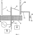
На фиг.1 приведена схема предлагаемого устройства для возбуждения высокочастотного факельного разряда.Figure 1 shows a diagram of the proposed device for exciting a high-frequency flare.
Устройство для возбуждения высокочастотного факельного разряда содержит цилиндрическую диэлектрическую трубку 1, установленную в пазу диэлектрического фланца 2. В осевом отверстии фланца 2 размещен полый силовой электрод 3 так, что его один конец заглушен и расположен внутри диэлектрической трубки 1, а другой конец выведен за ее пределы. Конец силового электрода 3, расположенный за пределами диэлектрической трубки 1, снабжен двумя штуцерами 4 и 5. Первый штуцер 4, расположенный на торце силового электрода 3, соединен с системой водоснабжения 6 (СВ). Второй штуцер 5, ориентированный перпендикулярно оси силового электрода 3, соединен с системой канализации 7 (СК). Конец силового электрода 3, расположенный за пределами диэлектрической трубки 1, электрически связан с высоковольтным электродом высокочастотного генератора 8. На силовом электроде 3 радиально, под острым углом к его оси, установлен дополнительный электрод 9, конец которого заострен и направлен к месту соприкосновения диэлектрической трубки 1 и внешнего электрода 10, который своей вогнутой стороной охватывает часть внешней поверхности диэлектрической трубки 1. Внешний электрод 10 установлен на одном конце штанги 11, выполненной с возможностью перемещения параллельно оси диэлектрической трубки 1. Второй конец штанги 11 через закрепленную на ней электроизолирующую вставку 12 соединен с приводом 13.A device for exciting a high-frequency flare discharge comprises a cylindrical dielectric tube 1 mounted in the groove of the dielectric flange 2. A
Диэлектрическая трубка 1 изготовлена из кварцевого стекла. Фланец 2 выполнен из термостойкого диэлектрика, например, фторопласта. В качестве силового электрода 3 использована медная трубка. Для формирования штуцеров 4 и 5 использованы медные трубки диаметра, меньшего, чем диаметр силового электрода 3. В качестве высокочастотного генератора 8 может быть использован, например, ВЧГ-2/4 (4 кВт, 17 МГц). Дополнительный электрод 9 представляет собой медный стержень. Внешний электрод 10 изготовлен из листа латуни, загнутого по цилиндрической поверхности. Подвижная штанга 11 представляет собой стальной стержень. В качестве материала для электроизолирующей вставки 12 может быть использован фторопласт. В качестве привода 13 использован шаговый электродвигатель MOTS 1 (12 В, 32 мА).The dielectric tube 1 is made of quartz glass. Flange 2 is made of heat-resistant dielectric, for example, fluoroplastic. As the
При работе устройства для возбуждения высокочастотного факельного разряда непрерывно подают воду в силовой электрод 3 через штуцер 4 из системы водоснабжения 6 (СВ) и сливают воду из силового электрода 3 через штуцер 5 в систему канализации 7 (СК). Включают привод 13, приближают внешний электрод 10 к наружной поверхности диэлектрической трубки 1 и соответственно к дополнительному электроду 9, расположенному на силовом электроде 3 внутри объема, ограниченного диэлектрической трубкой 1. С помощью высокочастотного генератора 8 подают высокочастотное напряжение на силовой 3 и дополнительный 9 электроды. За счет емкостной связи между силовым электродом 3 и внешним электродом 10 осуществляют электрический пробой промежутка между внешним электродом 10 и заостренным концом дополнительного электрода 9 и возбуждают барьерный разряд между дополнительным электродом 9 и внутренней поверхностью диэлектрической трубки 1. С помощью привода 13 внешний электрод 10 перемещают параллельно оси диэлектрической трубки 1 в направлении формирования плазменного потока. Этим переносят барьерный разряд с заостренного конца дополнительного электрода 9 на силовой электрод 3. С помощью барьерного разряда возбуждают высокочастотный факельный разряд с силового электрода 3.When the device for exciting a high-frequency flare discharge is continuously supplied with water to the
Эксперименты показали, что напряжение, необходимое для возбуждения барьерного разряда между дополнительным электродом 9 и внутренней поверхностью диэлектрической трубки 1, снижается с уменьшением радиуса кривизны заостренного конца дополнительного электрода 9. В экспериментах использовались дополнительные электроды с различными радиусами кривизны заостренного конца. Внешний диаметр диэлектрической трубки 1 составлял 60 мм. Толщина стенки диэлектрической трубки 1 составляла 3 мм. Результаты представлены в таблице 1.The experiments showed that the voltage required to excite a barrier discharge between the additional electrode 9 and the inner surface of the dielectric tube 1 decreases with a decrease in the radius of curvature of the pointed end of the additional electrode 9. In the experiments, additional electrodes with different radii of curvature of the pointed end were used. The outer diameter of the dielectric tube 1 was 60 mm. The wall thickness of the dielectric tube 1 was 3 mm. The results are presented in table 1.
Таким образом, уменьшено напряжение, необходимое для возбуждения барьерного разряда в устройстве для возбуждения высокочастотного факельного разряда.Thus, the voltage required to initiate a barrier discharge in a device for exciting a high-frequency flare discharge is reduced.
Claims (1)
Priority Applications (1)
| Application Number | Priority Date | Filing Date | Title |
|---|---|---|---|
| RU2012122809/07A RU2499373C1 (en) | 2012-06-01 | 2012-06-01 | Device to excite high-frequency flare discharge |
Applications Claiming Priority (1)
| Application Number | Priority Date | Filing Date | Title |
|---|---|---|---|
| RU2012122809/07A RU2499373C1 (en) | 2012-06-01 | 2012-06-01 | Device to excite high-frequency flare discharge |
Publications (1)
| Publication Number | Publication Date |
|---|---|
| RU2499373C1 true RU2499373C1 (en) | 2013-11-20 |
Family
ID=49710233
Family Applications (1)
| Application Number | Title | Priority Date | Filing Date |
|---|---|---|---|
| RU2012122809/07A RU2499373C1 (en) | 2012-06-01 | 2012-06-01 | Device to excite high-frequency flare discharge |
Country Status (1)
| Country | Link |
|---|---|
| RU (1) | RU2499373C1 (en) |
Cited By (3)
| Publication number | Priority date | Publication date | Assignee | Title |
|---|---|---|---|---|
| RU2633707C2 (en) * | 2016-04-07 | 2017-10-17 | Евгений Владимирович Беспала | Device for generating high-frequency discharge plasma |
| RU2713214C1 (en) * | 2019-10-10 | 2020-02-04 | федеральное государственное автономное образовательное учреждение высшего образования «Национальный исследовательский Томский политехнический университет» | Device for flare discharge excitation |
| RU2717841C1 (en) * | 2019-10-15 | 2020-03-26 | Федеральное государственное бюджетное учреждение науки Институт физики твердого тела Российской академии наук (ИФТТ РАН) | Collinear electrode |
Citations (4)
| Publication number | Priority date | Publication date | Assignee | Title |
|---|---|---|---|---|
| RU2127220C1 (en) * | 1997-11-10 | 1999-03-10 | Александр Александрович Луканин | Ozonizer and ozone generator |
| US6126779A (en) * | 1996-11-28 | 2000-10-03 | Aea Technology Plc | Plasma gas processing |
| US6213999B1 (en) * | 1995-03-07 | 2001-04-10 | Sherwood Services Ag | Surgical gas plasma ignition apparatus and method |
| US7608839B2 (en) * | 2005-08-05 | 2009-10-27 | Mcgill University | Plasma source and applications thereof |
-
2012
- 2012-06-01 RU RU2012122809/07A patent/RU2499373C1/en not_active IP Right Cessation
Patent Citations (4)
| Publication number | Priority date | Publication date | Assignee | Title |
|---|---|---|---|---|
| US6213999B1 (en) * | 1995-03-07 | 2001-04-10 | Sherwood Services Ag | Surgical gas plasma ignition apparatus and method |
| US6126779A (en) * | 1996-11-28 | 2000-10-03 | Aea Technology Plc | Plasma gas processing |
| RU2127220C1 (en) * | 1997-11-10 | 1999-03-10 | Александр Александрович Луканин | Ozonizer and ozone generator |
| US7608839B2 (en) * | 2005-08-05 | 2009-10-27 | Mcgill University | Plasma source and applications thereof |
Cited By (3)
| Publication number | Priority date | Publication date | Assignee | Title |
|---|---|---|---|---|
| RU2633707C2 (en) * | 2016-04-07 | 2017-10-17 | Евгений Владимирович Беспала | Device for generating high-frequency discharge plasma |
| RU2713214C1 (en) * | 2019-10-10 | 2020-02-04 | федеральное государственное автономное образовательное учреждение высшего образования «Национальный исследовательский Томский политехнический университет» | Device for flare discharge excitation |
| RU2717841C1 (en) * | 2019-10-15 | 2020-03-26 | Федеральное государственное бюджетное учреждение науки Институт физики твердого тела Российской академии наук (ИФТТ РАН) | Collinear electrode |
Similar Documents
| Publication | Publication Date | Title |
|---|---|---|
| CN101395973B (en) | Plasma generator and method of generating plasma using the same | |
| CN102269093B (en) | For the igniter of the fuel/air mixture in ignition combustion room | |
| CN108322983B (en) | Floating electrode enhanced dielectric barrier discharge diffuse plasma jet generator | |
| CN204827767U (en) | Ignition and ignition system | |
| CN111970807A (en) | Device for exciting microwave plasma based on sliding arc discharge | |
| TWI400010B (en) | Apparatus and method for forming a plasma | |
| CN1777347A (en) | Corona coupling medium discharge-blocking device for generating low-temperature plasma | |
| RU2007129398A (en) | ATMOSPHERIC PRESS PLASMATRON | |
| RU2499373C1 (en) | Device to excite high-frequency flare discharge | |
| CN101378616A (en) | Atmosphere plasma cylindrical microwave excitation cavity | |
| JP2010541167A5 (en) | ||
| RU2001115747A (en) | METHOD FOR PRODUCING FULLERY-CONTAINING SOOT AND DEVICE FOR ITS IMPLEMENTATION | |
| CN103444024A (en) | Corona igniter having controlled location of corona formation | |
| CN104505325A (en) | Electronic gun device for high-voltage gas discharge | |
| CN102361531A (en) | Device and method for generating large-area, uniform and non-magnetized plasmas | |
| JP2016130512A (en) | Ignition method and ignition system | |
| RU2270491C2 (en) | High-frequency neutron source such as neutralizer | |
| CN107124812A (en) | Atmospheric pressure glow plasma generating device and textile material processing device | |
| CN109104808A (en) | A kind of novel microwave excitation device of long life | |
| RU2003110016A (en) | HIGH FREQUENCY SOURCE OF ELECTRONS, IN PARTICULAR NEUTRALIZER | |
| JP2004221019A (en) | Method and device for igniting microwave plasma under atmospheric pressure | |
| CN116170931B (en) | Device and method for enhancing discharge power based on DBD | |
| US12478794B2 (en) | Plasma device for skin treatment | |
| JP6261100B2 (en) | Atmospheric pressure inductively coupled plasma device | |
| RU2398328C2 (en) | Gas ionisation method |
Legal Events
| Date | Code | Title | Description |
|---|---|---|---|
| MM4A | The patent is invalid due to non-payment of fees |
Effective date: 20140602 |