RU2498091C1 - Method of operation of thermal power plant - Google Patents
Method of operation of thermal power plant Download PDFInfo
- Publication number
- RU2498091C1 RU2498091C1 RU2012130105/06A RU2012130105A RU2498091C1 RU 2498091 C1 RU2498091 C1 RU 2498091C1 RU 2012130105/06 A RU2012130105/06 A RU 2012130105/06A RU 2012130105 A RU2012130105 A RU 2012130105A RU 2498091 C1 RU2498091 C1 RU 2498091C1
- Authority
- RU
- Russia
- Prior art keywords
- steam
- feedwater
- turbine
- feed water
- sent
- Prior art date
Links
Images
Abstract
Description
Изобретение относится к области теплоэнергетики и может быть использовано на тепловых электростанциях.The invention relates to the field of power engineering and can be used in thermal power plants.
Известен способ работы тепловой электрической станции, включающей прямоточный котел, паровую турбину, состоящую из цилиндра высокого давления (ЦВД), цилиндра среднего давления (ЦСД) и цилиндра низкого давления (ЦНД), конденсатор пара паровой турбины, конденсатные насосы, регенеративные подогреватели низкого давления (ПНД), деаэратор питательной воды (ДПВ), насос питательной воды, снабженный турбоприводом (ПТН), регенеративные подогреватели высокого давления (ПВД), по которому пар из первых трех отборов паровой турбины отводят на ПВД, а из последних шести - на ПНД, в которых последовательно нагревают основной конденсат турбины после конденсатора и питательную воду; второй отбор осуществляется из «холодной» линии промежуточного перегрева (ХПП) пара, по которой пар после ЦВД направляется в промежуточный пароперегреватель (ПП) прямоточного котла и, далее, направляется в ЦСД; из третьего отбора также отводят пар на ДПВ и турбопривод питательного насоса, отработавший пар которого направляется на вход цилиндра низкого давления турбины (Ю.Ф.Косяк «Паровая турбина К-300-240 ХТГЗ» - М.: Энергоиздат, 1982. С.12).A known method of operation of a thermal power plant, including a once-through boiler, a steam turbine, consisting of a high pressure cylinder (CVP), a medium pressure cylinder (CPS) and a low pressure cylinder (CPS), a steam condenser of a steam turbine, condensate pumps, low pressure regenerative heaters ( PND), feed water deaerator (DPA), feed water pump equipped with a turbo drive (ПТН), high pressure regenerative heaters (LDPE), through which steam from the first three withdrawals of a steam turbine is diverted to LDPE, and from Latter six - IPA, which successively heated main turbine condensate after the condenser and the feedwater; the second selection is carried out from the “cold” line of the intermediate superheat (CSP) of the steam, through which the steam after the central heating system is sent to the intermediate superheater (PP) of the direct-flow boiler and, then, is sent to the central cylinder; from the third selection, steam is also diverted to the ДПВ and the turbine drive of the feed pump, the spent steam of which is sent to the inlet of the low-pressure cylinder of the turbine (Yu.F. Kosyak “Steam turbine K-300-240 KhTGZ” - M .: Energoizdat, 1982. P.12 )
Недостатком аналога является пониженная экономичность тепловой электрической станции из-за высокой разности температур пара третьего отбора турбины и питательной воды на выходе первого по ходу питательной воды ПВД.A disadvantage of the analogue is the reduced efficiency of the thermal power plant due to the high temperature difference of the steam of the third turbine and feed water outlet at the outlet of the first LDPE feed water.
Наиболее близким к заявляемому изобретению является способ подогрева питательной воды на тепловой электрической станции, по которому питательная вода последовательно нагревается паром отборов турбины в ПНД, ДПВ и ПВД, параллельно с последними часть питательной воды подогревается в выносном пароохладителе первого по ходу питательной воды подогревателя высокого давления, причем дренаж греющего пара из третьего по ходу питательной воды ПВД сливается во второй, а из второго и первого - отдельными потоками в ДПВ (патент RU 2053374).Closest to the claimed invention is a method of heating feed water at a thermal power plant, in which feed water is sequentially heated by steam turbine offsets in HDPE, DPV and LDPE, in parallel with the latter, part of the feed water is heated in a remote desuperheater of the first high pressure heater along the feed water, moreover, the drainage of heating steam from the third LDPE along the feed water is discharged into the second, and from the second and first by separate flows into the RPA (patent RU 2053374).
Недостатками прототипа является пониженная экономичность тепловой электростанции из-за большой разности температур пара на входе в выносной пароохладитель и питательной воды на выходе из него, а также дренажа второго по ходу питательной воды ПВД и питательной воды в ДПВ.The disadvantages of the prototype is the reduced efficiency of the thermal power plant due to the large difference in temperature of the steam at the inlet to the remote desuperheater and feed water at the outlet, as well as the drainage of the second LDPE feed water and feed water in the DPA.
Задачей нового способа является повышение экономичности тепловой электрической станции.The objective of the new method is to increase the efficiency of the thermal power plant.
Техническим результатом, достигаемым настоящим изобретением, является снижение разности температур между паром на входе в первый по ходу питательной воды ПВД и питательной водой на выходе из него.The technical result achieved by the present invention is to reduce the temperature difference between the steam at the inlet of the first LDPE feed water and the feed water at the exit thereof.
Технический результат достигается тем, что в способе работы тепловой электрической станции пар из первых трех отборов паровой турбины подают на ПВД, а из последних шести - на ПНД, в которых последовательно нагревают основной конденсат турбины после конденсатора и питательную воду; второй отбор осуществляется из «холодной» линии промежуточного перегрева (ХПП) пара, по которой пар после ЦВД направляется в промежуточный пароперегреватель (ПП) прямоточного котла и, далее, направляется в ЦСД, также из ХПП пар подается в турбодетандер, находящийся на одном валу с ПТН, после расширения в турбодетандере пар подается в первый по ходу питательной воды ПВД и ДПВ; из третьего отбора также отводят пар на турбопривод питательного насоса, отработавший пар которого направляется на вход цилиндра низкого давления паровой турбины.The technical result is achieved by the fact that in the method of operation of a thermal power plant, steam from the first three selections of the steam turbine is fed to the LDPE, and of the last six to the HDPE, in which the main condensate of the turbine after the condenser and feed water are sequentially heated; the second selection is carried out from the “cold” line of intermediate overheating (CSP) of the steam, through which the steam after the CVP is sent to the intermediate superheater (PP) of the direct-flow boiler and, then, is sent to the CPS, also from the CSP, the steam is fed to a turboexpander located on one shaft with PTN, after expansion in a turboexpander, steam is supplied to the first LDPE and DPV along the feed water; steam is also taken from the third selection to the turbo drive of the feed pump, the spent steam of which is sent to the inlet of the low pressure cylinder of the steam turbine.
Таким образом, пар, проходя через турбодетандер, расширяется, совершая работу, которая передается на вал ПТН, в результате чего его температура снижается, почти достигая температуру насыщения в первом по ходу питательной воды ПВД, отчего разность температур между паром на входе в первый по ходу питательной воды ПВД и питательной водой на выходе из него значительно сокращается и, следовательно, сокращаются необратимые потери в процессе теплообмена между паром и питательной водой, что повышает полезную работу цикла Ренкина и экономичность тепловой электрической станции.Thus, the steam passing through the turboexpander expands, performing work that is transmitted to the PTN shaft, as a result of which its temperature decreases, almost reaching the saturation temperature in the first in the course of the LDPE feed water, which makes the temperature difference between the steam at the inlet of the first in the course LDPE feed water and feed water at the outlet of it are significantly reduced and, consequently, irreversible losses during heat exchange between steam and feed water are reduced, which increases the useful work of the Rankine cycle and efficiency thermal power station.
Особенность заключается в том, что пар, направляемый в ДПВ и первый по ходу питательной воды ПВД, подается из ХПП и расширяется в турбодетандере до давления, равного давлению в третьем отборе паровой турбины, а работа, совершаемая паром в турбодетандере, передается на вал ПТН.The peculiarity lies in the fact that the steam sent to the DPV and the first along the LDPE feed water is supplied from the HPP and expanded in the turboexpander to a pressure equal to the pressure in the third extraction of the steam turbine, and the work performed by the steam in the turboexpander is transferred to the PTN shaft.
Новый способ работы тепловой электрической станции позволяет повысить экономичность тепловой электрической станции за счет снижения потерь от необратимости процесса теплообмена между паром и питательной водой, в первом по ходу питательной воды ПВД.A new way of operating a thermal power plant allows you to increase the efficiency of a thermal power plant by reducing losses from the irreversibility of the heat exchange process between steam and feed water, in the first along the feed water of the LDPE.
Таким образом, совокупность существенных признаков, изложенных в формуле изобретения, позволяет достичь желаемого технического результата.Thus, the set of essential features set forth in the claims, allows to achieve the desired technical result.
Далее рассмотрим сведения, подтверждающие возможность осуществления изобретения с получением искомого технического результата.Next, we consider the information confirming the possibility of carrying out the invention with obtaining the desired technical result.
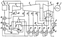
На чертеже изображена принципиальная схема тепловой электрической станции, поясняющая предложенный способ. Станция содержит паровой котел 1, пароперегреватель свежего пара 2, промежуточный пароперегреватель 3, паровую турбину с девятью отборами пара 20-25 и 27-29, состоящую из ЦВД 4, ЦСД 5 и ЦНД 6, электрический генератор 7, конденсатор 8, конденсатный насос 9, ПНД 10, ДПВ 11, питательный насос 12 и турбопривод питательного насоса 13, турбодетандер 14, трубопровод подвода пара в турбодетандер 15, трубопровод отвода пара из турбодетандера в первый по ходу питательной воды ПВД 16, первый по ходу питательной воды ПВД 17, второй по ходу питательной воды ПВД 18, третий по ходу питательной воды ПВД 19, линия отвода пара из турбопривода питательного насоса 26.The drawing shows a schematic diagram of a thermal power plant, explaining the proposed method. The station contains a steam boiler 1, a superheater of fresh steam 2, an
Рассмотрим пример реализации заявленного способа работы тепловой электрической станции.Consider an example of the implementation of the claimed method of operation of a thermal power plant.
Вырабатываемый в прямоточном паровом котле 1 пар после пароперегревателя свежего пара 2 направляют в ЦВД 4 паровой турбины, где он расширяется, совершая работу, передаваемую на электрический генератор 7, а затем часть отработавшего пара направляется на второй по ходу питательной воды ПВД 18 и в турбодетандер 14, остальная часть пара поступает в промежуточный пароперегреватель 3, а затем в ЦСД 5 и ЦНД 6, где пар расширяется, совершая работу, передаваемую на электрический генератор 7, после чего пар конденсируется в конденсаторе 8 и насосом 9 направляется через ПНД 10, где конденсат подогревается паром отборов 23-25 и 27-29 и паром из трубопровода отвода пара из турбопривода питательного насоса 26 и далее поступает в ДПВ 11, где происходит его подогрев и деаэрация паром, выходящим из турбодетандера 14; далее питательная вода из ДПВ 11 подается питательным насосом 12 через подогреватели высокого давления 17-19, где она подогревается паром отборов 20 и 21 и по трубопроводу 16 паром из турбодетандера и далее поступает в прямоточный паровой котел 1.The steam generated in the once-through steam boiler after the superheater of fresh steam 2 is sent to the HPP 4 of the steam turbine, where it expands, completing the work transferred to the electric generator 7, and then part of the exhaust steam is sent to the
Таким образом, использование турбодетандера 14 для расширения пара второго отбора 20 до давления, равного давлению пара третьего отбора 22, и замещение крайне перегретого пара третьего отбора, подающегося в ДПВ 11 и первый по ходу питательной воды ПВД 17, паром, отработавшим в турбодетандере 14, позволяет в значительной степени снизить потери от необратимости процесса теплообмена в ДПВ 11 и первом по ходу питательной воды ПВД 17, что повышает полезную работу цикла Ренкина и экономичность тепловой электрической станции.Thus, the use of a
Claims (1)
Priority Applications (1)
| Application Number | Priority Date | Filing Date | Title |
|---|---|---|---|
| RU2012130105/06A RU2498091C1 (en) | 2012-07-16 | 2012-07-16 | Method of operation of thermal power plant |
Applications Claiming Priority (1)
| Application Number | Priority Date | Filing Date | Title |
|---|---|---|---|
| RU2012130105/06A RU2498091C1 (en) | 2012-07-16 | 2012-07-16 | Method of operation of thermal power plant |
Publications (1)
| Publication Number | Publication Date |
|---|---|
| RU2498091C1 true RU2498091C1 (en) | 2013-11-10 |
Family
ID=49683197
Family Applications (1)
| Application Number | Title | Priority Date | Filing Date |
|---|---|---|---|
| RU2012130105/06A RU2498091C1 (en) | 2012-07-16 | 2012-07-16 | Method of operation of thermal power plant |
Country Status (1)
| Country | Link |
|---|---|
| RU (1) | RU2498091C1 (en) |
Cited By (5)
| Publication number | Priority date | Publication date | Assignee | Title |
|---|---|---|---|---|
| RU2560621C1 (en) * | 2014-04-09 | 2015-08-20 | Федеральное государственное бюджетное образовательное учреждение высшего профессионального образования "Казанский государственный энергетический университет" (ФГБОУ ВПО "КГЭУ") | Heat power plant operation mode |
| RU2562738C1 (en) * | 2014-04-18 | 2015-09-10 | Федеральное государственное бюджетное образовательное учреждение высшего профессионального образования "Казанский государственный энергетический университет" (ФГБОУ ВПО "КГЭУ") | Utilisation method of thermal energy generated by thermal power plant |
| RU2562741C1 (en) * | 2014-05-06 | 2015-09-10 | Федеральное государственное бюджетное образовательное учреждение высшего профессионального образования "Казанский государственный энергетический университет" (ФГБОУ ВПО "КГЭУ") | Utilisation method of thermal energy generated by thermal power plant |
| RU2562724C1 (en) * | 2014-05-06 | 2015-09-10 | Федеральное государственное бюджетное образовательное учреждение высшего профессионального образования "Казанский государственный энергетический университет" (ФГБОУ ВПО "КГЭУ") | Utilisation method of thermal energy generated by thermal power plant |
| RU2570131C2 (en) * | 2014-04-09 | 2015-12-10 | Федеральное государственное бюджетное образовательное учреждение высшего профессионального образования "Казанский государственный энергетический университет" (ФГБОУ ВПО "КГЭУ") | Operating method of thermal power plant |
Citations (6)
| Publication number | Priority date | Publication date | Assignee | Title |
|---|---|---|---|---|
| GB1238352A (en) * | 1967-10-06 | 1971-07-07 | ||
| SU501185A1 (en) * | 1972-08-23 | 1976-01-30 | Предприятие П/Я А-3513 | Power plant |
| SU1268752A1 (en) * | 1985-05-31 | 1986-11-07 | Краснодарский ордена Трудового Красного Знамени политехнический институт | Thermal power plant |
| RU2053374C1 (en) * | 1988-08-22 | 1996-01-27 | Научно-производственное объединение "Турбоатом" | Method of preheating of feed water |
| RU2010124798A (en) * | 2010-06-16 | 2011-12-27 | Рашид Зарифович Аминов (RU) | METHOD FOR INCREASING POWER OF A TWO-CIRCUIT ATOMIC POWER UNIT |
| EP2444595A1 (en) * | 2010-10-19 | 2012-04-25 | Kabushiki Kaisha Toshiba | Steam turbine plant |
-
2012
- 2012-07-16 RU RU2012130105/06A patent/RU2498091C1/en not_active IP Right Cessation
Patent Citations (6)
| Publication number | Priority date | Publication date | Assignee | Title |
|---|---|---|---|---|
| GB1238352A (en) * | 1967-10-06 | 1971-07-07 | ||
| SU501185A1 (en) * | 1972-08-23 | 1976-01-30 | Предприятие П/Я А-3513 | Power plant |
| SU1268752A1 (en) * | 1985-05-31 | 1986-11-07 | Краснодарский ордена Трудового Красного Знамени политехнический институт | Thermal power plant |
| RU2053374C1 (en) * | 1988-08-22 | 1996-01-27 | Научно-производственное объединение "Турбоатом" | Method of preheating of feed water |
| RU2010124798A (en) * | 2010-06-16 | 2011-12-27 | Рашид Зарифович Аминов (RU) | METHOD FOR INCREASING POWER OF A TWO-CIRCUIT ATOMIC POWER UNIT |
| EP2444595A1 (en) * | 2010-10-19 | 2012-04-25 | Kabushiki Kaisha Toshiba | Steam turbine plant |
Cited By (5)
| Publication number | Priority date | Publication date | Assignee | Title |
|---|---|---|---|---|
| RU2560621C1 (en) * | 2014-04-09 | 2015-08-20 | Федеральное государственное бюджетное образовательное учреждение высшего профессионального образования "Казанский государственный энергетический университет" (ФГБОУ ВПО "КГЭУ") | Heat power plant operation mode |
| RU2570131C2 (en) * | 2014-04-09 | 2015-12-10 | Федеральное государственное бюджетное образовательное учреждение высшего профессионального образования "Казанский государственный энергетический университет" (ФГБОУ ВПО "КГЭУ") | Operating method of thermal power plant |
| RU2562738C1 (en) * | 2014-04-18 | 2015-09-10 | Федеральное государственное бюджетное образовательное учреждение высшего профессионального образования "Казанский государственный энергетический университет" (ФГБОУ ВПО "КГЭУ") | Utilisation method of thermal energy generated by thermal power plant |
| RU2562741C1 (en) * | 2014-05-06 | 2015-09-10 | Федеральное государственное бюджетное образовательное учреждение высшего профессионального образования "Казанский государственный энергетический университет" (ФГБОУ ВПО "КГЭУ") | Utilisation method of thermal energy generated by thermal power plant |
| RU2562724C1 (en) * | 2014-05-06 | 2015-09-10 | Федеральное государственное бюджетное образовательное учреждение высшего профессионального образования "Казанский государственный энергетический университет" (ФГБОУ ВПО "КГЭУ") | Utilisation method of thermal energy generated by thermal power plant |
Similar Documents
| Publication | Publication Date | Title |
|---|---|---|
| JP5674922B2 (en) | Energy recovery and steam supply for increased power output in combined cycle power systems | |
| RU2498091C1 (en) | Method of operation of thermal power plant | |
| RU2691881C1 (en) | Thermal power plant | |
| RU2542725C2 (en) | Steam-turbine plant with steam turbine assembly and process steam user and its operation method | |
| RU2496992C1 (en) | Method of operation of thermal power plant | |
| EP2172622A3 (en) | Method and system for cooling steam bypassed from a steam turbine | |
| CN103062744A (en) | Heat recovery steam generator and methods of coupling same to combined cycle power plant | |
| US10287922B2 (en) | Steam turbine plant, combined cycle plant provided with same, and method of operating steam turbine plant | |
| JP6986842B2 (en) | How to operate a steam power plant and a steam power plant to implement this method | |
| JP2010038160A (en) | System and method for use in combined or rankine cycle power plant | |
| CN105090926A (en) | Oxy boiler power plant with a heat integrated air separation unit | |
| RU2602649C2 (en) | Steam turbine npp | |
| JP2015068314A (en) | Fuel gas heating facility and combined cycle power generation plant | |
| AU2010299977B2 (en) | Steam power plant | |
| RU2752123C1 (en) | Thermal power station | |
| EP2472072B1 (en) | A saturated steam thermodynamic cycle for a turbine and an associated installation | |
| JP2016070526A (en) | Boiler, combined cycle plant and boiler steam cooling method | |
| RU2561776C2 (en) | Combined-cycle plant | |
| KR102101166B1 (en) | Reheating of working fluid inside turbine system for power generation | |
| RU2748362C1 (en) | Method for operation of thermal power station | |
| CN104832227A (en) | Coal-fired unit efficient subcritical system | |
| RU2747786C1 (en) | Thermal power station | |
| RU2686541C1 (en) | Steam-gas plant | |
| RU2432468C1 (en) | Steam-turbine thermal power plant operating method and device for its implementation | |
| RU2291970C1 (en) | Method for operation of thermal power station |
Legal Events
| Date | Code | Title | Description |
|---|---|---|---|
| MM4A | The patent is invalid due to non-payment of fees |
Effective date: 20140717 |