RU2494308C1 - General-purpose vacuum atmospheric deaeration plant - Google Patents
General-purpose vacuum atmospheric deaeration plant Download PDFInfo
- Publication number
- RU2494308C1 RU2494308C1 RU2012112105/06A RU2012112105A RU2494308C1 RU 2494308 C1 RU2494308 C1 RU 2494308C1 RU 2012112105/06 A RU2012112105/06 A RU 2012112105/06A RU 2012112105 A RU2012112105 A RU 2012112105A RU 2494308 C1 RU2494308 C1 RU 2494308C1
- Authority
- RU
- Russia
- Prior art keywords
- water
- pipe
- vapor
- deaeration
- steam
- Prior art date
Links
Images
Abstract
Description
Изобретение относится к области энергетики и может быть использовано для термической деаэрации подпиточной воды тепловых сетей и питательной воды паровых котлов.The invention relates to the field of energy and can be used for thermal deaeration of makeup water of heating networks and feed water of steam boilers.
Наибольшее распространение в энергетике России для деаэрации подпиточной воды теплосети получили атмосферные деаэраторы струйного и струйно-барботажного типа ДА и ДСА и вакуумные деаэраторы типа ДВ и ДСВ. (см. Л.1, стр.49, рис.23 и рис.24 И.И. Оликер «Термическая деаэрация воды в отопительно-производственных котельных и тепловых сетях». Издательство литературы по строительству. Ленинград 1972.) и струйно-барботажного типа (Л.1, стр.54, 55, рис.27, 28).The most widespread in the Russian energy sector for deaeration of make-up water of the heating network are atmospheric deaerators of the jet and jet-bubbled type DA and DSA and vacuum deaerators of the DV and DSV type. (see L.1, p. 49, Fig. 23 and Fig. 24 I.I. Oliker “Thermal deaeration of water in heating and production boilers and heating networks.” Publishing House of Building Literature. Leningrad 1972.) and jet-bubbler type (L.1, p. 54, 55, fig. 27, 28).
Деаэрационные установки струйно-барботажного типа имеют много недостатков, приводящих к их неудовлетворительной работе:Deaeration units of jet-bubble type have many disadvantages leading to their unsatisfactory operation:
1. Требуют большого удельного выпара. При нормативном выпаре (1,5-2,0 кг на тонну деаэрированной воды для атмосферных деаэраторов и 5 кг/т.д.в. - для вакуумных) резко падает качество деаэрации.1. They require a large specific evaporation. With normative evaporation (1.5-2.0 kg per ton of deaerated water for atmospheric deaerators and 5 kg / so on for vacuum), the quality of deaeration drops sharply.
2. Требуют обязательной подачи пара в деаэратор. Не могут работать на «начальном эффекте» (без подачи греющей деаэрирующей среды). При этом конденсат, образованный при конденсации греющего пара уходит в теплосеть и пропадает для использования в паровых котлах и его приходится компенсировать дорогостоящей обессоленной водой.2. They require the obligatory supply of steam to the deaerator. They cannot work on the “initial effect” (without supplying a heating deaerating medium). In this case, the condensate formed during condensation of the heating steam goes into the heating system and disappears for use in steam boilers and it has to be compensated for with expensive demineralized water.
3. Имеют малую глубину регулирования производительности.3. Have a shallow depth of performance regulation.
4. Имеют большую металлоемкость.4. Have a large metal consumption.
5. При пуске наблюдаются сильные гидроудары.5. During start-up, severe water hammer is observed.
Указанные недостатки устранены в деаэрационных установках с центробежновихревьми деаэраторами (ДЦВ) конструкции Зимина Б.А., защищенного Патентом РФ №2131555 «Деаэратор (тепломассообменник)». Таковы деаэрационные установки, защищенные Патентами РФ №№1454781; 2242672; 2300050; 2373456; 2400432; 2402491. Они могут работать атмосферном режиме, если труба отвода выпара после охладителя выпара соединена с атмосферой, и в вакуумном режиме, если труба выпара соединена с эжектором. (О работе деаэрационных установок с деаэратором ДЦВ см. приложение-отзыв ТЭЦ-9 «Иркутскэнерго» и публикации в журналах):These shortcomings were eliminated in deaeration plants with centrifugal vortex deaerators (DCV) designed by B. Zimin, protected by RF Patent No. 2131555 “Deaerator (heat and mass exchanger)”. These are deaeration plants protected by Patents of the Russian Federation No. 14454781; 2242672; 23,000,050; 2,373,456; 2,400,432; 2402491. They can operate in atmospheric mode if the vapor removal pipe after the vapor cooler is connected to the atmosphere, and in vacuum mode if the vapor pipe is connected to the ejector. (For the operation of deaeration plants with a DHW deaerator, see the appendix of the Irkutskenergo TPP-9 and publications in magazines):
Л.2. 3имин Б.А. Опыт реконструкции деаэрационных установок // Промышленная энергетика. 1999. №11. С.11-14.L.2. 3imin B.A. Experience in the reconstruction of deaeration plants // Industrial Energy. 1999. No. 11. S.11-14.
Л.3. Коновалов В.К. Зимин. Б.А Реконструкция деаэрационных установок на Каширской ГРЭС // Энергетик. 2000. №4. С.28-29.L.3. Konovalov V.K. Zimin. B.A. Reconstruction of deaeration plants at Kashirskaya GRES // Energetik. 2000. No4. S.28-29.
Л.4. 3имин Б.А. Нужно ли запрещать работу вакуумных деаэраторов? // Энергетик. 2009. №12. С.15-16.L.4. 3imin B.A. Is it necessary to prohibit the operation of vacuum deaerators? // Energetic. 2009. No. 12. S.15-16.
Л.5. 3имин Б.А. Решение проблем деаэрации воды при переводе паровых котлов в водогрейный режим // Новости теплоснабжения. 2001. №1. С.28-30.L.5. 3imin B.A. Solving the problems of water deaeration when transferring steam boilers to the hot water mode // News of heat supply. 2001. No1. S.28-30.
Л.6. Зимин Б.А. Проблемы деаэрации воды в энергетике и способ их решения // Новости теплоснабжения. 2006. №1. С.40-44).L.6. Zimin B.A. Problems of water deaeration in the energy sector and method of solving them // News of heat supply. 2006. No1. S.40-44).
Высокую эффективность и экономию показали сетевые деаэраторы (деаэраторы подпитки теплосети) при переводе их из атмосферного в вакуумный режим работы. (На ТЭЦ-5 «Новосибирскэнерго» шесть деаэраторов ДСА400, переведенные в вакуумный режим работы, Черепетская ГРЭС - Деаэратор ДСА-300, переведенный в вакуумный режим работы с нагрузкой 600 т/ч, Кировская котельная г.Омска - деаэратор ДСА300, переведенный в вакуумный режим работы с нагрузкой 600 т/ч и др.). Эти деаэрационные установки, внедренные на открытых системах теплоснабжения дали большой эффект.Network deaerators (de-aerators of heating network recharge) were shown to be highly efficient and economical when transferring them from atmospheric to vacuum operation. (At CHPP-5 “Novosibirskenergo”, six DSA400 deaerators put into vacuum operation, Cherepetskaya TPP - DSA-300 deaerator, put into vacuum operation with a load of 600 t / h, Omsk Kirov boiler-house - DSA300 deaerator transferred to vacuum operating mode with a load of 600 t / h, etc.). These deaeration plants, implemented on open heating systems, have had a great effect.
Недостатки аналогов, деаэраторационных установок с центробежно-вихревыми деаэраторами, работающими в вакуумном режиме, появились после опубликования Постановления Главного государственного санитарного врача Российской Федерации от 7 апреля 2009 г. N 20 г.Москва от «Об утверждении СанПиН 2.1.4.2496-09» и его вредительского пункта (написанного некомпетентными в энергетике людьми или вредителями), подставившего Главного санитарного врача: «При открытой системе теплоснабжения деаэрация должна проводиться при температуре более 100°С». Проектные организации и ТЭЦ восприняли этот вредительский пункт постановления, как запрет на установку вакуумных деаэраторов при открытых системах теплоснабжения, так как выпускаемые промышленностью деаэраторы могут нагреть воду до 100,1°С только в атмосферном режиме (Если бы постановление вышло ранее, то вышеуказанные вакуумные деаэрационные установки не были бы внедрены. Об этом опубликована статья Зимина Б.А в «Энергетике» №12 за 2009 год).Deficiencies of analogues, deaeration units with centrifugal-vortex deaerators operating in a vacuum mode appeared after the publication of the Decree of the Chief State Sanitary Doctor of the Russian Federation of April 7, 2009
В качестве прототипа выберем деаэрационную установку атмосферного типа, изображенную на стр.29 журнала «Энергетик» №4 за 2000 год.As a prototype, we will choose an atmospheric deaeration plant, shown on
Установка содержит бак-аккумулятор деаэрированной воды (БА), центробежно-вихревой деаэратор ДЦВ (первая ступень деаэрации), с подводящими трубопроводами деаэрируемой воды и пара (или без подвода пара, если вода нагрета выше температуры насыщения, соответствующей давлению в деаэраторе), подогреватель деаэрируемой воды поверхностный или контактный (например, по Патенту РФ №2210043), (или без него, если деаэратор служит для деаэрации питательной воды котлов и имеет подводящий паропровод в ДЦВ), капельный деаэратор КД (устройство, диспергирующее деаэрируемую воду в паровом пространстве бака-аккумулятора), контактный охладитель выпара ОВК с подводящим и отводящим трубопроводами охлаждающей воды, с отводящим трубопроводом отвода неконденсируемых газов в атмосферу, который можно присоединить к эжектору и деаэратор становится вакуумны, бак сбора охлаждающей воды (БОВ), нагретой в ОВК, насос отвода охлаждающей воды из БОВ.The installation contains a storage tank for deaerated water (BA), a centrifugal vortex deaerator DCV (first stage of deaeration), with supply pipes for deaerated water and steam (or without steam supply, if the water is heated above the saturation temperature corresponding to the pressure in the deaerator), and a heater is deaerated surface or contact water (for example, according to RF Patent No. 22210043), (or without it, if the deaerator serves to deaerate the boiler feed water and has a supply steam line to the DHW), KD drip deaerator (dispersing device deaerated water in the vapor space of the storage tank), a contact cooler for the HVAC vapor with the inlet and outlet pipes of the cooling water, with the outlet pipe for the removal of non-condensable gases into the atmosphere, which can be connected to the ejector and the deaerator becomes vacuum, the collection tank for cooling water (BOW) is heated in HVAC, a pump for draining cooling water from a BOW
Недостатком прототипа служит то, что указанная деаэрационная установка (без эжектора) может работать только в атмосферном режиме. Это приводит к повышенному расходу пара на нагрев воды выше 100°С, к необходимости установки охладителя деаэрированной воды после деаэрационной установки (нельзя, например, подавать в аккумуляторные баки подпиточную воду для тепловой сети, нагретую выше 90°С). Если в проекте будет нарисован эжектор, то люди, неправильно понимающие Постановление №20 Санитарного врача, забракуют эту установку, как вакуумную, работающую при температуре ниже 100°С.The disadvantage of the prototype is that the specified deaeration plant (without ejector) can only work in atmospheric mode. This leads to increased steam consumption for heating water above 100 ° C, to the need to install a deaerated water cooler after the deaeration installation (for example, it is impossible to supply make-up water for heating networks heated above 90 ° C to the battery tanks). If an ejector is drawn in the project, then people who misunderstand Decree No. 20 of the Sanitary Doctor will reject this installation as a vacuum unit operating at a temperature below 100 ° C.
Целью настоящего изобретения является создание деаэрационной установки, не имеющей водоструйного эжектора, могущей работать как в атмосферном, так и в вакуумном режимах без нарушения вредительского Постановления Главного Санитарного врача, т.е., обеспечить деаэрацию воды (в том числе и в вакуумном режиме) при доведении температуры деаэрируемой воды перед деаэратором до 100,1°С, которая будет охлаждаться в деаэрационной установке за счет вскипания при давлении ниже атмосферного (при вакууме) и образования выпара, а так же позволит обмануть некомпетентных людей (или вредителей), пугающихся названия «вакуумный» из-за неправильной интерпритации вышеуказанного Постановления. №20. (Постановление не запрещает работу вакуумных деаэраторов, а только рекомендует нагревать воду выше 100°С).The aim of the present invention is the creation of a deaeration plant that does not have a water-jet ejector, which can operate both in atmospheric and in vacuum modes without violating the harmful order of the Chief Sanitary Doctor, i.e., to ensure deaeration of water (including in vacuum mode) when bringing the temperature of the deaerated water in front of the deaerator to 100.1 ° C, which will be cooled in the deaeration unit due to boiling at a pressure below atmospheric (under vacuum) and the formation of vapor, as well as allow to deceive incompetent people (or pests), frightened of the name "vacuum" due to incorrect interpretation of the above Resolution. No. 20. (The resolution does not prohibit the operation of vacuum deaerators, but only recommends heating water above 100 ° C).
Указанная цель достигается тем, что в известной деаэрационной установке, содержащей бак-аккумулятор деаэрированной воды, центробежно-вихревой деаэратор (ДЦВ), являющийся первой ступенью деаэрационной установки, с трубопроводами подвода деаэрируемой воды и пара (или без трубопровода подвода пара), капельный деаэратор (КД), являющийся второй ступенью установки и представляющий собой перфорированную трубу, расположенную в паровом пространстве бака-аккумулятора и соединенную с ДЦВ, подогреватель деаэрируемой воды поверхностного или контактного типа (или без него), контактный охладитель выпара (ОВК) с подводящим трубопроводом выпара из бака - аккумулятора и из ДЦВ, с подводящим и отводящим трубопроводами охлаждающей воды, с отводящим трубопроводом отвода неконденсируемых газов в атмосферу, имеющим запорный орган, бак сбора охлаждающей воды (БОВ), нагретой в ОВК, в качестве контактного охладителя выпара установлен центробежно-вихревой эжектор (ЦВЭ), содержащий цилиндрический корпус с условно верхней и нижней торцевыми крышками, подводящий патрубок выпара, присоединенный к условно верхней крышке, как минимум один подводящий тангенциальный патрубок охлаждающей рабочей воды, присоединенный к корпусу в верхней части (к входному отсеку), отводящий тангенциальный патрубок, присоединенный к нижней части корпуса, причем этот тангенциальный патрубок присоединен тангенциально к верхней части циклона-сепаратора, содержащим цилиндрический корпус с условно верхней и нижней торцевыми крышками, с отводящим патрубком неконденсируемых газов, проходящим через верхнюю крышку, соединеным с атмосферой и имеющим запорный орган (кран, задвижку), тангенциальный отводящий патрубок отработанной охлаждающей воды, соединенный с баком сбора отработавшей охлаждающей воды или со свободным сливом.This goal is achieved by the fact that in a known deaeration installation containing a storage tank of deaerated water, a centrifugal vortex deaerator (DCV), which is the first stage of a deaeration installation, with pipelines for supplying deaerated water and steam (or without a steam supply pipe), drip deaerator ( KD), which is the second stage of the installation and which is a perforated pipe located in the vapor space of the storage tank and connected to the DHW, a heater for deaerated surface water or type (or without it), a contact evaporator cooler (HVAC) with an inlet pipe for evaporating from a tank - an accumulator and from an DHW, with inlet and outlet pipes for cooling water, with a discharge pipe for removing non-condensable gases to the atmosphere, which has a shut-off element, a cooling collection tank water (BOV), heated in the HVAC, a centrifugal vortex ejector (CVE) is installed as a contact cooler for the vapor; it contains a cylindrical body with conditionally upper and lower end caps, the inlet pipe for the vapor attached to like the top cover, at least one inlet tangential branch pipe of cooling working water connected to the housing in the upper part (to the inlet compartment), the outlet tangential branch pipe connected to the lower part of the housing, and this tangential branch pipe is connected tangentially to the upper part of the cyclone separator containing cylindrical body with conditionally upper and lower end caps, with a discharge pipe of non-condensable gases passing through the top cover, connected to the atmosphere and having a shut-off RGANI (cock valve), a tangential discharge pipe of spent cooling water tank connected with the collection of spent cooling water, or with a free drain.
Внутри корпуса ЦВЭ установлена кольцевая перегородка (шайба), делящая корпус на входной и выходной отсеки.An annular partition (washer) is installed inside the CVE housing, dividing the housing into the input and output compartments.
Тангенциальный патрубок отвода охлаждающей воды из ОВК служит одновременно отводящим патрубком неконденсируемых газов.The tangential branch pipe for the discharge of cooling water from the HVAC serves simultaneously as a branch pipe for non-condensable gases.
Узел ЦВЭ вместе с циклоном - сепаратором представляет собой контактный охладитель выпара ОВК. При открытом запорном органе на трубопроводе отвода неконденсируемых газов в атмосферу ОВК работает только как контактный охладитель выпара (конденсатор водяных паров), а при закрытом - не только, как конденсатор водяных паров выпара, но и как эжектор, обеспечивающий работу деаэрационной установки под невысоким вакуумом (до 0,5 кгс/см).The CVE unit together with the cyclone - separator is a contact cooler for the HVAC vapor. When the shut-off element is open on the non-condensable gas discharge pipe to the atmosphere, the HVAC operates only as a contact cooler for the vapor (water vapor condenser), and when closed, not only as a condenser of the steam vapor vapor, but also as an ejector ensuring the operation of the deaeration unit under low vacuum ( up to 0.5 kgf / cm).
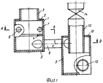
На фиг.1 изображен продольный разрез контактного охладителя выпара - ОВК.Figure 1 shows a longitudinal section of a contact cooler vapor - HVAC.
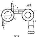
На фиг.2 - поперечный разрез ОВК.Figure 2 is a transverse section of the HVAC.
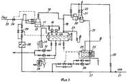
На фиг.3 - схема вакуумно-атмосферной деаэрационной установки.Figure 3 is a diagram of a vacuum-atmospheric deaeration plant.
Контактный охладитель выпара (конденсатор водяных паров выпара) - ОВК содержит корпус 1 с верхней 2 и нижней 3 торцевыми крышками. Внутри средней части корпуса 1 имеется кольцевая перегородка 4 (шайба), делящая внутреннюю часть корпуса на входной и выходной отсеки. К верхней крышке 2 присоединен патрубок 5 подвода выпара из бака-аккумулятора и из ДЦВ. К корпусу входного отсека присоединены тангенциальные патрубки 6 и 7 подвода охлаждающей воды. К нижней части корпуса (к выходному отсеку) присоединен тангенциальный патрубок 8 отвода охлаждающей воды (она же рабочая вода, создающая эжектирующий эффект). Патрубок 8 тангенциально присоединен к циклону-сепаратору, содержащему цилиндрический корпус 9, с верхней 10 и нижней 11 торцевыми крышками. В нижней части корпуса 9 имеется тангенциальный патрубок 12 отвода охлаждающей (рабочей) воды. Через верхнюю крышку 10 проходит патрубок 13 отвода неконденсируемых газов, соединенный с атмосферой и имеющий запорный орган 14.Contact evaporator cooler (evaporator water vapor condenser) - HVAC contains a housing 1 with upper 2 and lower 3 end caps. Inside the middle part of the housing 1 there is an annular partition 4 (washer) dividing the inner part of the housing into the input and output compartments. To the
Деаэрационная установка (фиг.3) имеет бак-аккумулятор деаэрированной воды 14, Центробежно-вихревой деаэратор 15, Два капельных деаэратора 16. Труба 17, соединяет ЦВД и КД. Трубы 18 и 19, соединяет бак 1 и ДЦВ с контактным охладителем выпара 20 (ОВК), имеющим вестовую трубу 21 с запорным органом 22 (задвижкой, краном). Имеется вестовая труба 23, соединяющая бак 1 с атмосферой. Имеется бак 24 слива охлаждающей воды из ОВК, который является баком - газоотделителем. Внутри бака 24 имеется приемный стакан-газоотделитель 25. Насос 26 служит для откачки воды из бака 24 в трубопровод 27. По трубопроводу 27 подается химочищенная вода на деаэрационную установку через подогреватель деаэрируемой воды 28 и регулятор 29 уровня воды в баке 14. Трубопровод 30 - ответвление от трубопровода 27 на ОВК. По трубопроводу 31 вода из ОВК сливается в бак 24. Насосы 32 служат для откачки деаэрированной воды из бака - аккумулятора 14 в обратный сетевой трубопровод или на питание паровых котлов. Паропровод 33 служит для подачи греющего пара в ДЦВ для безгидроударного нагрева воды в случае надобности (в деаэраторах подпитки теплосети предпочтительнее нагревать деаэрируемую воду в поверхностном подогревателе 28, чтобы не терять конденсат в теплосети. В питательный деаэраторах паровых котлов предпочтительнее нагревать воду паром в ДЦВ без использования поверхностного подогревателя 28, так как весь конденсат греющего пара используется в паровых котлах). Регулятор 34 регулирует расход пара в ДЦВ. Вакуумно-атмосферный гидрозатвор 35 обеспечивает безопасность процесса деаэрации воды. Пробоотборник 26 служит для взятия проб воды на анализ.The deaeration unit (Fig. 3) has a storage tank for
Работа деаэрационной установки осуществляется следующим образомThe operation of the deaeration plant is as follows
Вариант 1 (работа в качестве деаэратора подпитки теплосети в вакуумном режиме)Option 1 (work as a deaerator of heating system recharge in a vacuum mode)
Химочищеная вода по трубопроводу 27 подается в центробежно-вихревой деаэратор 15 через поверхностный подогреватель 28, где нагревается до температуры 100,1°С или более. Если подогреватель 28 не может нагреть воду до 101,1 оС, то можно дать греющий пар в ДЦВ (15) по паропроводу 33. Пар нагревает воду безгидроударно от любой температуры (В сетевых деаэраторах предпочтительнее нагревать воду до нужной температуры в поверхностных подогревателях (29), чтобы не терять конденсат, необходимый для питания паровых котлов). В ДЦВ деаэрируемая вода освобождается от растворенных агрессивных газов на 98-99%. Далее она по трубопроводу 17 поступает в капельные деаэраторы 16 (КД), в головной части которых вода приобретает вращательное движение. Вода, перегретая выше температуры насыщения, выходит из КД в паровое пространство бака 14 через перфорации и разбрызгивается на мелкие капли. Каждая капля воды вскипает, образуя выпар. С выпаром из воды удаляются остатки агрессивных газов, обеспечивая высокое качество деаэрации воды. Выпар из бака 14 и из ДЦВ (15) удаляется по выпарным трубам 18 и 19 и попадает в контактный охладитель выпара 20.Dry water through a
Контактный охладитель выпара 20 (ОВК) работает следующим образом (см. фиг.1, 2). Выпар из бака-аккумулятора 14 и из ДЦВ (15) поступает по выпарному трубопроводу 18, через патрубок 5 внутрь корпуса 1 ОВК. Охлаждающая (рабочая) вода по трубопроводу 30 поступает внутрь корпуса 1 через тангенциальные патрубки 7. Вода приобретает вращательное движение с вертикальной границей раздела фаз (с вертикальным уровнем воды). Толщину вращающегося слоя воды определяет диаметр отверстия в шайбе 4. По мере уменьшения радиуса закрутки воды скорость ее вращения увеличивается, а давление падает (закон сохранения количества движения). Выпар контактирует с вращающейся поверхностью воды, и водяные пары выпара конденсируются (коэффициент теплопередачи от пара к воде при непосредственном контакте в 2000 раз выше, чем при контакте через стенку поверхности нагрева). После прохождения вращающимся потоком воды шайбы 4 вода попадает в тангенциальный патрубок 8, и далее в циклон-сепаратор. Поток воды захватывает неконденсируемые газы. Далее водогазовый поток попадает внутрь корпуса 9 циклона-сепаратора через тангенциальный патрубок 8 и приобретает вращательное движение. Запорный орган (задвижка) на патрубке 13 (трубопроводе 21) - закрыта. Вращающийся водогазовый поток смеси охлаждающей воды и неконденсируемых газов устремляется в тангенциальный патрубок 12 и далее в бак 24, создавая эждектирующий эффек. К эжектирующему эффекту прибавляется эффект сифона, создающий дополнительный вакуум за счет разности высот ОВК и бака 24. В баке-аккумлуляторе создается вакуум порядка 0,5 кгс/см2, при котором температура насыщения (кипения) равна 80°С. Если деаэрируемую воду нагреть в подогревателе 28 до 85°С, то деаэратор будет работать на «начальном эффекте». Вода вскипит, даст выпар, за счет чего охладится (на 1°С в ДЦВ и на 4°С в каплях парового пространства бака 1). Выпор составит 1,6×5°С=8 кг на тонну деаэрируемой воды.Contact cooler vapor 20 (HVAC) works as follows (see figure 1, 2). Evaporate from the
Вариант 2 (работа в качестве питательного деаэратора паровых котлов в атмосферном режиме). Запорный орган 22 (задвижка) на выпарной трубе 21 открыт. Разница с вариантом 1 заключается в нагреве деаэрируемой воды непосредственно в ДЦВ за счет подачи в него пара по трубопроводу 33, и в открытии запорного органа 22 (задвижки) на трубопроводе 21 (на фиг.1; 2 - патрубок 13, задвижка 14). Выгоднее нагревать воду не в поверхностном подогревателе 28, а подавать пар непосредственно в ДЦВ (15), так как конденсат греющего пара используется по назначению в паровом котле вместе с питательной водой. Отпадает необходимость в установке поверхностного подогревателя 28 и в его эксплуатации. ДЦВ позволяет нагревать воду безгидроударно от любой температуры за счет барботажа пара через вращающийся слой воды. Возможно вместо поверхностного нагревателя воды 28 установить контактный (смешивающий) водонагреватель (например, защищенный Патентом РФ №2210043) и подавать в ДЦВ воду, перегретую выше температуры насыщения. Когда открыта задвижка 22 (фиг.3) 14 (фиг.1), то бак-аккумулятор 1 работает при нулевом давлении (или при небольшом давлении - 0,05 кгс/см2. Это атмосферный режим работы. В ОВК газы отделяются от воды за счет центробежного эффекта и выходят через патрубок 13 в атмосферу, а отработавшая охлаждающая вода устремляется в тангенциальный патрубок 12 и далее в бак 24. Если задвижку 22 (14) закрыть, то деаэратор начинает работать в вакуумном режиме с вакуумом до 0,5 кгс/см2.Option 2 (work as a nutrient deaerator of steam boilers in atmospheric mode). The locking element 22 (valve) on the
Выполнение контактного охладителя выпара ОВК в виде центробежно-вихревого эжектора ЦВЭ в паре с циклоном-сепаратором обеспечивает возможность работы деаэрационной установки, как в атмосферном, так и в вакуумном режимах. Причем вакуумный режим достигается без применения (в дополнение к ОВК) струйных эжекторов и вакуумных насосов. Это значительно упрощает схему, уменьшает расход воды на систему обеспечения вакуума, уменьшает расход энергии на привод насосов рабочей воды. Кроме этого, позволяет обеспечить вакуумный режим работы деаэраторов (что значительно экономичней атмосферного) не нарушая Постановления №20 (нагреваем воду до 100,1°С и далее охлаждаем ее в деаэраторе за счет образования выпара). Вакуумный режим работы сетевых деаэраторов позволяет подавать деаэрированную воду в аккумуляторные баки без охлаждения ее в теплообменниках-охладителях деаэрированной воды (не устанавливать теплообменники-охладители, что упрощает схему).The implementation of the contact cooler for the OVK vapor in the form of a centrifugal-vortex ejector CVE paired with a cyclone separator provides the possibility of operation of the deaeration unit, both in atmospheric and in vacuum modes. Moreover, the vacuum mode is achieved without the use (in addition to HVAC) of jet ejectors and vacuum pumps. This greatly simplifies the circuit, reduces the flow rate of water to the vacuum supply system, and reduces the flow rate of energy to drive the working water pumps. In addition, it allows to ensure the vacuum operation of deaerators (which is much more economical than atmospheric) without violating Resolution No. 20 (we heat water to 100.1 ° C and then cool it in the deaerator due to the formation of vapor). The vacuum operating mode of the network deaerators allows to supply deaerated water to the storage tanks without cooling it in deaerated water heat exchangers-coolers (do not install heat exchangers-coolers, which simplifies the circuit).
Claims (3)
Priority Applications (1)
| Application Number | Priority Date | Filing Date | Title |
|---|---|---|---|
| RU2012112105/06A RU2494308C1 (en) | 2012-03-29 | 2012-03-29 | General-purpose vacuum atmospheric deaeration plant |
Applications Claiming Priority (1)
| Application Number | Priority Date | Filing Date | Title |
|---|---|---|---|
| RU2012112105/06A RU2494308C1 (en) | 2012-03-29 | 2012-03-29 | General-purpose vacuum atmospheric deaeration plant |
Publications (1)
| Publication Number | Publication Date |
|---|---|
| RU2494308C1 true RU2494308C1 (en) | 2013-09-27 |
Family
ID=49254110
Family Applications (1)
| Application Number | Title | Priority Date | Filing Date |
|---|---|---|---|
| RU2012112105/06A RU2494308C1 (en) | 2012-03-29 | 2012-03-29 | General-purpose vacuum atmospheric deaeration plant |
Country Status (1)
| Country | Link |
|---|---|
| RU (1) | RU2494308C1 (en) |
Cited By (2)
| Publication number | Priority date | Publication date | Assignee | Title |
|---|---|---|---|---|
| RU2629066C1 (en) * | 2016-02-25 | 2017-08-24 | Общество С Ограниченной Ответственностью "Евробион" | Non-chemical water treatment device |
| CN113855817A (en) * | 2021-08-12 | 2021-12-31 | 阜阳市乾丰茶业有限公司 | Deoxidizing and sterilizing device for chrysanthemum processing and sterilizing method thereof |
Citations (5)
| Publication number | Priority date | Publication date | Assignee | Title |
|---|---|---|---|---|
| JPS5481442A (en) * | 1977-12-13 | 1979-06-28 | Toshiba Corp | Deaerator exhaust retrieving system |
| SU1183778A1 (en) * | 1984-01-27 | 1985-10-07 | Предприятие П/Я А-3513 | Thermal deaerator |
| RU2300050C1 (en) * | 2005-11-22 | 2007-05-27 | Борис Алексеевич Зимин | Vacuum deairing machine |
| RU2373456C2 (en) * | 2007-05-14 | 2009-11-20 | Борис Алексеевич Зимин | Deaeration plant |
| RU2402491C1 (en) * | 2009-02-10 | 2010-10-27 | Борис Алексеевич Зимин | Deaerating plant |
-
2012
- 2012-03-29 RU RU2012112105/06A patent/RU2494308C1/en not_active IP Right Cessation
Patent Citations (5)
| Publication number | Priority date | Publication date | Assignee | Title |
|---|---|---|---|---|
| JPS5481442A (en) * | 1977-12-13 | 1979-06-28 | Toshiba Corp | Deaerator exhaust retrieving system |
| SU1183778A1 (en) * | 1984-01-27 | 1985-10-07 | Предприятие П/Я А-3513 | Thermal deaerator |
| RU2300050C1 (en) * | 2005-11-22 | 2007-05-27 | Борис Алексеевич Зимин | Vacuum deairing machine |
| RU2373456C2 (en) * | 2007-05-14 | 2009-11-20 | Борис Алексеевич Зимин | Deaeration plant |
| RU2402491C1 (en) * | 2009-02-10 | 2010-10-27 | Борис Алексеевич Зимин | Deaerating plant |
Cited By (2)
| Publication number | Priority date | Publication date | Assignee | Title |
|---|---|---|---|---|
| RU2629066C1 (en) * | 2016-02-25 | 2017-08-24 | Общество С Ограниченной Ответственностью "Евробион" | Non-chemical water treatment device |
| CN113855817A (en) * | 2021-08-12 | 2021-12-31 | 阜阳市乾丰茶业有限公司 | Deoxidizing and sterilizing device for chrysanthemum processing and sterilizing method thereof |
Similar Documents
| Publication | Publication Date | Title |
|---|---|---|
| RU2373461C1 (en) | Heat supply system | |
| JP2013523439A (en) | Vapor absorption system | |
| RU2412909C1 (en) | Desalination installation | |
| RU2494308C1 (en) | General-purpose vacuum atmospheric deaeration plant | |
| US20230134288A1 (en) | Device for desalination by liquid water jet compression | |
| CN209635926U (en) | Falling film evaporation couples absorption refrigeration high-salt sewage processing equipment | |
| RU2400432C1 (en) | Deaeration plant | |
| US3183174A (en) | Sea water distillation method and apparatus to provide a superpure distillate | |
| RU2767966C1 (en) | Water desalination method and device for implementation thereof | |
| CN108815869A (en) | Liquid-purifying device | |
| RU2365815C2 (en) | Installation for condensation of spent vapor of steam turbine and condensate deaeration | |
| RU2359917C1 (en) | Method of sea water desalination by utilising low-potential heat | |
| RU2090512C1 (en) | Installation for distilling liquids and evaporating solutions | |
| RU2402491C1 (en) | Deaerating plant | |
| WO2014140756A2 (en) | A system for processing brines | |
| RU2373456C2 (en) | Deaeration plant | |
| CN103539215A (en) | Sewage treatment system and process | |
| RU124375U1 (en) | CAPACITOR OF HEAT STATION TURBO INSTALLATION | |
| RU2661121C2 (en) | Shell-and-tube apparatus for heat recovery from hot process stream | |
| GB794379A (en) | Improvements in or relating to flash evaporating and condensing systems | |
| RU2242672C1 (en) | Deaeration unit | |
| RU2151341C1 (en) | Deaerator | |
| RU65395U1 (en) | Desalination plant | |
| CA1120798A (en) | Method and apparatus for feeding condensate to a high pressure vapor generator | |
| US3486987A (en) | Multi-stage distillation with direct contact water-immiscible liquid and serially connected ejectors |
Legal Events
| Date | Code | Title | Description |
|---|---|---|---|
| MM4A | The patent is invalid due to non-payment of fees |
Effective date: 20150330 |