RU2482529C2 - Device for image filming - Google Patents
Device for image filming Download PDFInfo
- Publication number
- RU2482529C2 RU2482529C2 RU2011135236/28A RU2011135236A RU2482529C2 RU 2482529 C2 RU2482529 C2 RU 2482529C2 RU 2011135236/28 A RU2011135236/28 A RU 2011135236/28A RU 2011135236 A RU2011135236 A RU 2011135236A RU 2482529 C2 RU2482529 C2 RU 2482529C2
- Authority
- RU
- Russia
- Prior art keywords
- image pickup
- heat dissipating
- pickup element
- air
- opening
- Prior art date
Links
Images


Classifications
-
- G—PHYSICS
- G03—PHOTOGRAPHY; CINEMATOGRAPHY; ANALOGOUS TECHNIQUES USING WAVES OTHER THAN OPTICAL WAVES; ELECTROGRAPHY; HOLOGRAPHY
- G03B—APPARATUS OR ARRANGEMENTS FOR TAKING PHOTOGRAPHS OR FOR PROJECTING OR VIEWING THEM; APPARATUS OR ARRANGEMENTS EMPLOYING ANALOGOUS TECHNIQUES USING WAVES OTHER THAN OPTICAL WAVES; ACCESSORIES THEREFOR
- G03B17/00—Details of cameras or camera bodies; Accessories therefor
- G03B17/55—Details of cameras or camera bodies; Accessories therefor with provision for heating or cooling, e.g. in aircraft
-
- H—ELECTRICITY
- H04—ELECTRIC COMMUNICATION TECHNIQUE
- H04N—PICTORIAL COMMUNICATION, e.g. TELEVISION
- H04N23/00—Cameras or camera modules comprising electronic image sensors; Control thereof
- H04N23/50—Constructional details
- H04N23/52—Elements optimising image sensor operation, e.g. for electromagnetic interference [EMI] protection or temperature control by heat transfer or cooling elements
-
- G—PHYSICS
- G03—PHOTOGRAPHY; CINEMATOGRAPHY; ANALOGOUS TECHNIQUES USING WAVES OTHER THAN OPTICAL WAVES; ELECTROGRAPHY; HOLOGRAPHY
- G03B—APPARATUS OR ARRANGEMENTS FOR TAKING PHOTOGRAPHS OR FOR PROJECTING OR VIEWING THEM; APPARATUS OR ARRANGEMENTS EMPLOYING ANALOGOUS TECHNIQUES USING WAVES OTHER THAN OPTICAL WAVES; ACCESSORIES THEREFOR
- G03B17/00—Details of cameras or camera bodies; Accessories therefor
- G03B17/02—Bodies
-
- H—ELECTRICITY
- H04—ELECTRIC COMMUNICATION TECHNIQUE
- H04N—PICTORIAL COMMUNICATION, e.g. TELEVISION
- H04N23/00—Cameras or camera modules comprising electronic image sensors; Control thereof
- H04N23/50—Constructional details
- H04N23/54—Mounting of pick-up tubes, electronic image sensors, deviation or focusing coils
-
- H—ELECTRICITY
- H04—ELECTRIC COMMUNICATION TECHNIQUE
- H04N—PICTORIAL COMMUNICATION, e.g. TELEVISION
- H04N23/00—Cameras or camera modules comprising electronic image sensors; Control thereof
- H04N23/50—Constructional details
- H04N23/55—Optical parts specially adapted for electronic image sensors; Mounting thereof
-
- G—PHYSICS
- G03—PHOTOGRAPHY; CINEMATOGRAPHY; ANALOGOUS TECHNIQUES USING WAVES OTHER THAN OPTICAL WAVES; ELECTROGRAPHY; HOLOGRAPHY
- G03B—APPARATUS OR ARRANGEMENTS FOR TAKING PHOTOGRAPHS OR FOR PROJECTING OR VIEWING THEM; APPARATUS OR ARRANGEMENTS EMPLOYING ANALOGOUS TECHNIQUES USING WAVES OTHER THAN OPTICAL WAVES; ACCESSORIES THEREFOR
- G03B2217/00—Details of cameras or camera bodies; Accessories therefor
- G03B2217/002—Details of arrangement of components in or on camera body
-
- H—ELECTRICITY
- H04—ELECTRIC COMMUNICATION TECHNIQUE
- H04N—PICTORIAL COMMUNICATION, e.g. TELEVISION
- H04N23/00—Cameras or camera modules comprising electronic image sensors; Control thereof
Abstract
Description
Предпосылки создания изобретенияBACKGROUND OF THE INVENTION
Область техники, к которой относится изобретениеFIELD OF THE INVENTION
Данное изобретение относится к устройству для съемки изображения, а более конкретно к конструкции для охлаждения элемента для съемки изображения.The present invention relates to an image pickup apparatus, and more particularly, to a structure for cooling an image pickup element.
Характеристика предшествующего уровня техникиDescription of the Related Art
Элементы для съемки изображения преобразуют свет в электрические сигналы. Когда температура элемента для съемки изображения возрастает, нежелательные составляющие шума накладываются на сигналы, выдаваемые элементом для съемки изображения, что приводит к снижению качества изображения. Поэтому важно охлаждать элемент для съемки изображения в устройстве, включающем в себя этот элемент для съемки изображения.Elements for capturing images convert light into electrical signals. When the temperature of the image pickup element increases, unwanted noise components are superimposed on the signals generated by the image pickup element, which leads to a decrease in image quality. Therefore, it is important to cool the image pickup element in a device including this image pickup element.
В выложенном патенте Японии № 2005-354637 описана конструкция, в которой элемент для съемки изображения механически соединен с корпусом устройства посредством элемента, рассеивающего тепло, так что тепло, генерируемое элементом для съемки изображения, рассеивается наружу через поверхность устройства за счет теплопроводности. Этот способ является недорогим и может быть воплощен посредством простой конструкции, вследствие чего широко применяется в узлах изделий.Japanese Patent Laid-Open No. 2005-354637 describes a structure in which an image pickup element is mechanically connected to the device body by means of a heat dissipating element, so that the heat generated by the image pickup element is dissipated outward through the surface of the device due to thermal conductivity. This method is inexpensive and can be implemented through a simple design, as a result of which it is widely used in product assemblies.
В выложенном патенте Японии № 2009-33718 (публикация заявки на патент США № 2009/0002549) описана конструкция, в которой элемент для съемки изображения принудительно охлаждается воздухом за счет формирования проточного канала воздуха вокруг элемента для съемки изображения. При осуществлении этого способа можно усилить эффект охлаждения и можно предотвратить возрастание температуры корпуса устройства. Таким образом, этот способ во многих аспектах выгоднее, чем вышеописанный способ, предусматривающий использование теплопередачи.Japanese Patent Laid-Open No. 2009-33718 (US Patent Application Publication No. 2009/0002549) describes a design in which an image pickup element is forcedly cooled by air by forming an air flow channel around the image pickup element. By implementing this method, the cooling effect can be enhanced and the temperature rise of the device casing can be prevented. Thus, this method is in many aspects more advantageous than the above-described method involving the use of heat transfer.
Устройства для съемки изображения, такие как цифровые камеры (фотоаппараты), в общем случае включают в себя механизм трансфокации, который изменяет угол обзора захватываемого изображения за счет перемещения одной или более групп линз, входящих в оптическую систему формирования изображения. Кроме того, недавно - как способ уменьшения габаритов оптической системы формирования изображения и повышения надежности - предложены конструкции, в которых элемент для съемки изображения, на котором формируют изображение, перемещается вместе с группами подвижных линз во время операции трансфокации.Image capturing devices, such as digital cameras (cameras), generally include a zoom mechanism that changes the viewing angle of the captured image by moving one or more groups of lenses included in the optical imaging system. In addition, recently - as a way to reduce the size of the optical imaging system and increase reliability - designs have been proposed in which the image pickup element on which the image is formed is moved together with groups of movable lenses during the zoom operation.
В конструкциях, где элемент для съемки изображения перемещается во время операции трансфокации, вышеописанные способы охлаждения страдают следующими проблемами.In designs where the image pickup element moves during the zoom operation, the above cooling methods suffer from the following problems.
То есть, по поводу способа охлаждения с использованием теплопередачи можно сказать, что трудно применить этот способ охлаждения к конструкции, в которой элемент для съемки изображения перемещается, поскольку элемент для съемки изображения должен быть механически соединен с корпусом устройства или аналогичным элементом конструкции посредством элемента, рассеивающего тепло.That is, regarding the cooling method using heat transfer, it can be said that it is difficult to apply this cooling method to a structure in which the image pickup element is moved, since the image pickup element must be mechanically connected to the device body or similar structural element by means of a diffusing element heat.
По поводу способа принудительного воздушного охлаждения можно сказать, что есть затруднения при формировании проточного канала воздуха вокруг элемента для съемки изображения. Более конкретно, поскольку положение элемента для съемки изображения изменяется во время операции трансфокации, нужно перемещать проточный канал воздуха в соответствии с положением элемента для съемки изображения. Это делает эффект охлаждения нестабильным.Regarding the forced air cooling method, it can be said that there are difficulties in forming an air flow channel around the image pickup element. More specifically, since the position of the image pickup element changes during the zoom operation, it is necessary to move the air flow channel in accordance with the position of the image pickup element. This makes the cooling effect unstable.
Соответственно, становится необходимым увеличение габаритов устройства для того, чтобы сформировать эффективный проточный канал воздуха в зависимости от расположения элемента для съемки изображения и от пространства вокруг элемента для съемки изображения. Кроме того, поскольку элемент для съемки изображения функционирует как часть механизма объектива, в объективе распространяется воздух. В результате, пыль попадает в объектив и рассеивается в объективе.Accordingly, it becomes necessary to increase the dimensions of the device in order to form an effective air flow channel depending on the location of the image pickup element and the space around the image pickup element. In addition, since the image pickup element functions as part of the lens mechanism, air is circulated in the lens. As a result, dust enters the lens and disperses in the lens.
Краткое изложение существа изобретенияSummary of the invention
В одном аспекте данного изобретения предложено устройство для съемки изображения, включающее в себя: элемент для съемки изображения; элемент, рассеивающий тепло, включающий в себя участок, рассеивающий тепло, и термически соединенный с элементом для съемки изображения за счет крепления к элементу для съемки изображения; корпус, который вмещает элемент для съемки изображения и элемент, рассеивающий тепло (отводящий тепло элемент), так что элемент для съемки изображения и элемент, рассеивающий тепло, имеют возможность перемещения, причем корпус имеет проем, в котором участок, рассеивающий тепло, раскрыт (подвергается воздействию) независимо от положения элемента для съемки изображения и элемента, рассеивающего тепло, в диапазоне подвижности; вентилятор, который создает воздушный поток; и короб, который образует проточный канал воздуха, направляющий воздушный поток, создаваемый вентилятором, к проему.In one aspect of the present invention, there is provided an image pickup apparatus, including: an image pickup member; a heat dissipating element including a heat dissipating portion and thermally connected to the image pickup element by attaching to the image pickup element; a housing that accommodates an image pickup element and a heat dissipating element (heat dissipating element), so that the image pickup element and a heat dissipating element are movable, the housing having an opening in which the heat dissipating portion is exposed (exposed exposure) regardless of the position of the image pickup element and the heat dissipating element in the range of mobility; a fan that creates air flow; and a box that forms a flow channel of air directing the air flow generated by the fan to the opening.
В соответствии с данным изобретением, оказывается возможным стабильное охлаждение элемента для съемки изображения независимо от положения элемента для съемки изображения, который заключен с возможностью перемещения в корпусе.In accordance with this invention, it is possible to stably cool the image pickup element, regardless of the position of the image pickup element, which is enclosed for movement in the housing.
Дополнительные признаки данного изобретения станут ясными из нижеследующего описания возможных вариантов осуществления, приводимого со ссылками на прилагаемые чертежи.Additional features of the present invention will become apparent from the following description of possible embodiments given with reference to the accompanying drawings.
Краткое описание чертежейBrief Description of the Drawings
На фиг. 1А-1С представлены перспективные изображения, иллюстрирующие цифровой фотоаппарат, соответствующий варианту осуществления.In FIG. 1A-1C are perspective views illustrating a digital camera according to an embodiment.
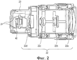
На фиг. 2 представлено сечение узла объектива, проведенное вдоль вертикальной плоскости, включающей в себя оптическую ось.In FIG. 2 is a sectional view of a lens assembly drawn along a vertical plane including an optical axis.
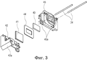
На фиг. 3 представлено перспективное изображение с пространственным разделением деталей узла для съемки изображения.In FIG. 3 shows a perspective image with a spatial separation of the parts of the site for capturing an image.
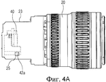
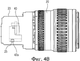
Фиг. 4А и 4В иллюстрируют положения участка, рассеивающего тепло, когда узел для съемки изображения перемещается в направлении оптической оси.FIG. 4A and 4B illustrate the positions of a heat dissipating portion when the image pickup unit moves in the direction of the optical axis.
На фиг. 5А и 5В представлены перспективные изображения, иллюстрирующие внешний вид узла охлаждения.In FIG. 5A and 5B are perspective views illustrating the appearance of a cooling unit.
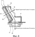
На фиг. 6 представлено сечение узла охлаждения, проведенное вдоль плоскости, перпендикулярной оптической оси.In FIG. 6 shows a section of a cooling unit drawn along a plane perpendicular to the optical axis.
На фиг. 7 представлено сечение узла объектива и узла охлаждения, проведенное вдоль плоскости, перпендикулярной оптической оси.In FIG. 7 is a sectional view of the lens assembly and the cooling assembly drawn along a plane perpendicular to the optical axis.
Описание вариантов осуществленияDescription of Embodiments
В качестве устройства для формирования изображения, соответствующего варианту осуществления данного изобретения, со ссылками на прилагаемые чертежи будет описана цифровая камера (цифровой фотоаппарат).As an image forming apparatus according to an embodiment of the present invention, a digital camera (digital camera) will be described with reference to the accompanying drawings.
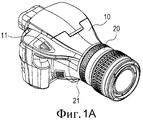
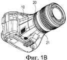
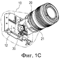
На фиг. 1А-1С представлены перспективные изображения, иллюстрирующие цифровой фотоаппарат, соответствующий данному варианту осуществления. На фиг. 1А и 1В представлены перспективные изображения, иллюстрирующие внешний вид цифрового фотоаппарата, соответствующего данному варианту осуществления, а на фиг. 1С представлено перспективное изображение, иллюстрирующее внутреннюю конструкцию цифрового фотоаппарата, соответствующего данному варианту осуществления.In FIG. 1A-1C are perspective views illustrating a digital camera according to this embodiment. In FIG. 1A and 1B are perspective views illustrating the appearance of a digital camera in accordance with this embodiment, and in FIG. 1C is a perspective view illustrating an internal structure of a digital camera in accordance with this embodiment.
Как показано на фиг. 1А и 1В, цифровой фотоаппарат, соответствующий данному варианту осуществления, содержит корпус 10 фотоаппарата и узел 20 объектива. Корпус 10 фотоаппарата включает в себя кнопку 11 трансфокации, а узел 20 объектива включает в себя кольцо 21 трансфокации. Как показано на фиг. 1С, в корпусе 10 фотоаппарата расположен контроллер 12. Контроллер 12 выполняет операцию трансфокации, которая является операцией уменьшения или увеличения поля зрения на основании сигналов, выдаваемых от кнопки 11 трансфокации или кольца 21 трансфокации.As shown in FIG. 1A and 1B, a digital camera according to this embodiment comprises a
Как показано на фиг. 1С, узел 20 объектива также включает в себя узел 30 охлаждения, предназначенный для охлаждения элемента для съемки изображения, который будет описан ниже.As shown in FIG. 1C, the
Теперь, со ссылками на фиг. 2, будет описана внутренняя конструкция узла 20 объектива. На фиг. 2 представлено сечение узла 20 объектива, проведенное вдоль вертикальной плоскости, включающей в себя оптическую ось. Узел 20 объектива включает в себя корпус 23 объектива, а в корпусе 23 объектива заключены группа 22 линз формирования изображения и узел 40 для съемки изображения.Now, with reference to FIG. 2, the internal structure of the
Группа 22 линз формирования изображения включает в себя первую группу 22а линз, вторую группу 22b линз, третью группу 22с линз и четвертую группу 22d линз. Изображение объекта проходит через группу 22 линз формирования изображения и фокусируется на узле 40 для съемки изображения. Корпус 23 объектива соответствует корпусу, который вмещает узел 40 для съемки изображения с возможностью его перемещения.The
В данном варианте осуществления, вторая группа 22b линз, четвертая группа 22d линз и узел 40 для съемки изображения являются подвижными группами, которые выполнены с возможностью перемещения в направлении оптической оси и приводятся в движение соответствующими исполнительными механизмами. Таким образом, каждая из подвижных групп перемещается в направлении оптической оси.In this embodiment, the
Когда пользователь задействует кнопку 11 трансфокации или кольцо 21 трансфокации, контроллер 12 осуществляет управление исполнительными механизмами соответствующим образом.When the user engages the
На фиг. 3 представлено перспективное изображение с пространственным разделением деталей узла 40 для съемки изображения. Узел 40 для съемки изображения включает в себя элемент 41 для съемки изображения, элемент 42, рассеивающий тепло, фильтр 43 нижних частот, резиновую втулку 44 и держатель 45, которые объединены друг с другом. Элемент 40 для съемки изображения преобразует изображение объекта, сфокусированное группой 22 линз формирования изображения, в электрические сигналы и выдает эти электрические сигналы. Элемент 40 для съемки изображения представляет собой фотоэлектрический преобразующий элемент, такой, как датчик на основе комплементарной структуры «метал - окисел - полупроводник» (КМОП-структуры) или датчик на основе прибора с зарядовой связью (ПЗС).In FIG. 3 is an exploded perspective view of an
Как показано на фиг. 3, элемент 42, рассеивающий тепло, включает в себя участок 42а, рассеивающий тепло. Участок 42а, рассеивающий тепло, имеет такую форму, что простирается в направлении оптической оси, так что участок 42а, рассеивающий тепло, раскрыт в проеме 25, который будет описан ниже, в корпусе 23 объектива независимо от положения узла 40 для съемки изображения в диапазоне его подвижности. Элемент 42, рассеивающий тепло, крепится к элементу 40 для съемки изображения таким образом, что элемент 42, рассеивающий тепло, находится в контакте с задней поверхностью элемента 40 для съемки изображения. Элемент 42, рассеивающий тепло, крепится также к держателю 45, тем самым обеспечивая функцию позиционирования элемента 41 для съемки изображения. Таким образом, элемент 42, рассеивающий тепло, термически соединен с элементом 41 для съемки изображения. Направляющие отверстия 45a выполнены в держателе 45 таким образом, что они простираются в направлении оптической оси, а через направляющие отверстия 45а вставлены направляющие валики 24, предусмотренные в узле 20 объектива. Таким образом, узел 40 для съемки изображения можно точно перемещать в направлении оптической оси.As shown in FIG. 3, the
Фиг. 4А и 4В иллюстрируют положения участка 42a, рассеивающего тепло, когда узел 40 для съемки изображения перемещается в направлении оптической оси в соответствии с операцией трансфокации узла 20 объектива. Проем 25 выполнен в боковой поверхности корпуса 23 объектива, а узел 40 для съемки изображения располагается в узле 20 объектива таким образом, что участок 42а, рассеивающий тепло, раскрыт (не защищен) в проеме 25. Фиг. 4А иллюстрирует состояние, в котором узел 40 для съемки изображения находится у заднего конца своего диапазона подвижности. В этом состоянии, передняя концевая часть участка 42а, рассеивающего тепло, раскрыта в проеме 25, и этот участок 42а, рассеивающий тепло, располагается так, что целиком закрывает проем 25. Фиг. 4В иллюстрирует состояние, в котором узел 40 для съемки изображения находится у переднего конца своего диапазона подвижности. В этом состоянии, задняя концевая часть участка 42а, рассеивающего тепло, раскрыта в проеме 25, и этот участок 42а, рассеивающий тепло, располагается так, что целиком закрывает проем 25. Таким образом, независимо от положения узла 40 для съемки изображения в его диапазоне подвижности, участок 42а, рассеивающий тепло, раскрыт в проеме 25 и располагается так, что целиком закрывает проем 25. Поэтому можно предотвратить попадание инородного вещества, такого как пыль, в узел 20 объектива через проем 25.FIG. 4A and 4B illustrate the positions of the
На фиг. 5А и 5В представлены перспективные изображения, иллюстрирующие внешний вид узла 30 охлаждения. Узел 30 охлаждения, короб 31 вентиляторов, дутьевой вентилятор 32 и нагнетательный вентилятор 33, которые объединены друг с другом. Нагнетательный вентилятор 32 соответствует первому вентилятору, а нагнетательный вентилятор 33 соответствует второму вентилятору. Короб 31 вентиляторов имеет выпускное отверстие 35, через которое выпускается воздух, всасываемый нагнетательным вентилятором 32, и впускное отверстие 36, через которое нагнетательный вентилятор 33 всасывает воздух. Нагнетательный вентилятор 32 имеет впускное отверстие 34 и плотно прикреплен к коробу 31 вентиляторов. Нагнетательный вентилятор 33 имеет выпускное отверстие 34 и плотно прикреплен к коробу 31 вентиляторов. Соответственно, короб 31 вентиляторов включает в себя первый проточный канал воздуха, по которому воздух всасывается через впускное отверстие 34 нагнетательным вентилятором 32 и выпускается через выпускное отверстие 35. Кроме того, короб 31 вентиляторов также включает в себя второй проточный канал воздуха, по которому воздух, находящийся в коробе 31 вентиляторов, выпускается через выпускное отверстие 37 нагнетательным вентилятором 33, так что через впускное отверстие 36 в короб 31 вентиляторов вводится свежий воздух.In FIG. 5A and 5B are perspective views illustrating the appearance of the cooling
На фиг. 6 представлено сечение узла 30 охлаждения, проведенное вдоль плоскости, перпендикулярной оптической оси. Короб 31 вентиляторов включает в себя первый проточный канал А воздуха, образованный нагнетательным вентилятором 32, и второй проточный канал В воздуха, образованный нагнетательным вентилятором 33. Как показано на фиг. 6, первый проточный канал А воздуха и второй проточный канал В воздуха пересекаются.In FIG. 6 is a section through a
В данном варианте осуществления, нагнетательный вентилятор 32 имеет характеристики высокого давления, так что в первом проточном канале А воздуха создается высокоскоростной воздушный поток с высокой направленностью и высокой локальной рабочей характеристикой воздушного охлаждения. Нагнетательный вентилятор 33 имеет большую скорость потока, так что во втором проточном канале В воздуха создается воздушный поток, который собирает воздух со всего внутреннего пространства короба 31 вентиляторов и равномерно вентилирует короб 31 вентиляторов. Поскольку нагнетательные вентиляторы 32 и 33 снабжены соответствующими впускными отверстиями, холодный внешний воздух, который непрерывно поступает в первый проточный канал А воздуха и второй проточный канал В воздуха, поддерживает рабочую характеристику вентиляции, которая соответствует большой скорости потока нагнетательного вентилятора 33. Таким образом, можно по максимуму использовать рабочую характеристику каждого проточного канала воздуха.In this embodiment, the
На фиг. 7 представлено сечение узла 20 объектива и узла 30 охлаждения, проведенное вдоль плоскости, перпендикулярной оптической оси, в положении около узла 40 для съемки изображения. Тепло, генерируемое элементом 41 для съемки изображения, передается через элемент 42, рассеивающий тепло (теплоотводящий элемент), на участок 42а, рассеивающий тепло (теплоотводящий участок), за счет теплопроводности (см. пунктирную линию на фиг. 7). Как показано на фиг. 7, когда узел 30 охлаждения крепится к узлу 20 объектива, выпускное отверстие 35 оказывается напротив проема 25. Таким образом, поскольку выпускное отверстие 35 сформировано, в коробе 31 вентиляторов образуется первый проточный канал А воздуха, который вызывает протекание воздуха, всасываемого нагнетательным вентилятором 32, в проем 25, сформированный в коробе 31 вентиляторов. Участок 42а, рассеивающий тепло, раскрыт внутрь короба 31 вентиляторов в проеме 25 и выпускном отверстии 35 и принудительно охлаждается, когда воздух, который течет по первому проточному каналу А воздуха с высокой скоростью, продувается на участок 42а, рассеивающий тепло. Как описано выше, участок 42а, рассеивающий тепло, имеет такую форму, что простирается в направлении оптической оси в положении около внутренней стенки корпуса 23 объектива. Поэтому участок 42а, рассеивающий тепло, раскрыт в проеме 25 независимо от положения узла 40 для съемки изображения, а проем 25 полностью закрыт участком 42а, рассеивающим тепло. Воздух, который нагнетается на участок 42а, рассеивающий тепло, и температура которого увеличилась, диспергируется в коробе 31 вентиляторов, а затем выпускается из короба 31 вентиляторов по второму проточному каналу В воздуха.In FIG. 7 is a sectional view of the
Вышеописанное устройство для съемки изображения, соответствующее данному варианту осуществления, обеспечивает следующие преимущества. То есть, элемент, рассеивающий тепло, который перемещается вместе с элементом для съемки изображения, локально охлаждается воздухом с помощью высокоскоростного воздушного потока, так что оказывается возможным эффективное охлаждение перемещающегося элемента для съемки изображения. Поскольку проточные каналы воздуха сформированы снаружи узла объектива, а механизм охлаждения и механизм съемки изображения конструктивно отделены друг от друга, механизм воздушного охлаждения можно оптимизировать, а габариты устройства можно уменьшить. Поскольку проем в корпусе объектива закрыт участком, рассеивающим тепло, независимо от положения элемента, рассеивающего тепло, можно гарантировать высокую стойкость узла объектива к проникновению пыли. Поскольку предусмотрено несколько нагнетательных вентиляторов, а эти нагнетательные вентиляторы снабжены соответствующими впускными отверстиями, эффект охлаждения можно максимизировать.The above-described image pickup apparatus according to this embodiment provides the following advantages. That is, a heat dissipating element that moves with the image pickup element is locally cooled by air using a high speed airflow, so that it is possible to efficiently cool the moving image pickup element. Since the air flow channels are formed outside the lens assembly, and the cooling mechanism and the image pickup mechanism are structurally separated from each other, the air cooling mechanism can be optimized, and the dimensions of the device can be reduced. Since the opening in the lens case is closed by a heat dissipating portion, regardless of the position of the heat dissipating element, it is possible to guarantee high resistance of the lens assembly to dust penetration. Since several discharge fans are provided, and these discharge fans are provided with corresponding inlet openings, the cooling effect can be maximized.
Хотя данное изобретение описано со ссылками на возможные варианты осуществления, следует понять, что изобретение не ограничивается описанными возможными вариантами осуществления. Объем притязаний нижеследующей формулы изобретения следует толковать в самом широком смысле как охватывающий все такие модификации, а также эквивалентные конструкции и функции.Although the present invention has been described with reference to possible embodiments, it should be understood that the invention is not limited to the described possible embodiments. The scope of the claims of the following claims should be construed in the broadest sense as encompassing all such modifications, as well as equivalent structures and functions.
Claims (4)
Applications Claiming Priority (2)
| Application Number | Priority Date | Filing Date | Title |
|---|---|---|---|
| JP2010-187126 | 2010-08-24 | ||
| JP2010187126A JP5631116B2 (en) | 2010-08-24 | 2010-08-24 | Imaging device |
Publications (2)
| Publication Number | Publication Date |
|---|---|
| RU2011135236A RU2011135236A (en) | 2013-02-27 |
| RU2482529C2 true RU2482529C2 (en) | 2013-05-20 |
Family
ID=44785228
Family Applications (1)
| Application Number | Title | Priority Date | Filing Date |
|---|---|---|---|
| RU2011135236/28A RU2482529C2 (en) | 2010-08-24 | 2011-08-23 | Device for image filming |
Country Status (6)
| Country | Link |
|---|---|
| US (1) | US8792023B2 (en) |
| EP (1) | EP2424222A3 (en) |
| JP (1) | JP5631116B2 (en) |
| KR (1) | KR101342969B1 (en) |
| CN (1) | CN102375296B (en) |
| RU (1) | RU2482529C2 (en) |
Families Citing this family (10)
| Publication number | Priority date | Publication date | Assignee | Title |
|---|---|---|---|---|
| CN102854714A (en) * | 2012-08-16 | 2013-01-02 | 浙江宇视科技有限公司 | Heat dissipation device of zoom camera |
| JP6048301B2 (en) * | 2013-04-25 | 2016-12-21 | 株式会社ニコン | Electronics |
| JP6120728B2 (en) * | 2013-08-27 | 2017-04-26 | キヤノン株式会社 | Optical equipment |
| US10194071B2 (en) | 2015-04-03 | 2019-01-29 | Red.Com, Llc | Modular motion camera |
| JP2018518080A (en) | 2015-04-03 | 2018-07-05 | レッド.コム,エルエルシー | Modular motion camera |
| JP6838262B2 (en) * | 2017-01-06 | 2021-03-03 | 日立Astemo株式会社 | Stereo camera |
| US10771659B2 (en) * | 2017-06-22 | 2020-09-08 | Canon Kabushiki Kaisha | Electronic apparatus and image pickup apparatus improved in heat dissipation structure |
| JP2019061055A (en) * | 2017-09-26 | 2019-04-18 | キヤノン株式会社 | Imaging device |
| WO2021011630A1 (en) * | 2019-07-16 | 2021-01-21 | Meso Scale Technologies, Llc. | Assay apparatuses, methods and reagents |
| CN110475052B (en) * | 2019-08-14 | 2021-05-28 | 淮安市洪泽区广电网络有限公司 | Heat dissipation type intelligent monitoring system with dust removal function |
Citations (7)
| Publication number | Priority date | Publication date | Assignee | Title |
|---|---|---|---|---|
| JP2005354637A (en) * | 2004-06-14 | 2005-12-22 | Canon Inc | Heat radiating structure for electronic apparatus, and electronic apparatus |
| JP2006010983A (en) * | 2004-06-24 | 2006-01-12 | Ricoh Co Ltd | Digital camera |
| US20070024743A1 (en) * | 2005-07-27 | 2007-02-01 | Sony Corporation | Camera apparatus |
| JP2007155776A (en) * | 2005-11-30 | 2007-06-21 | Fujifilm Corp | Lens barrel |
| US20090002549A1 (en) * | 2007-06-28 | 2009-01-01 | Olympus Imaging Corp. | Electronic camera |
| JP2009071722A (en) * | 2007-09-14 | 2009-04-02 | Olympus Imaging Corp | Electronic camera |
| JP2010136209A (en) * | 2008-12-05 | 2010-06-17 | Hitachi Kokusai Electric Inc | Cooling structure of camera revolving device |
Family Cites Families (15)
| Publication number | Priority date | Publication date | Assignee | Title |
|---|---|---|---|---|
| JPH02308559A (en) * | 1989-05-24 | 1990-12-21 | Fujitsu Ltd | Flexible heat transferring device |
| JPH04331580A (en) * | 1991-05-02 | 1992-11-19 | Canon Inc | Image pickup device equipped with radiating means |
| US5587739A (en) * | 1993-03-26 | 1996-12-24 | Nikon Corporation | Variable magnification image taking device |
| JP2005331549A (en) * | 2004-05-18 | 2005-12-02 | Konica Minolta Photo Imaging Inc | Hand shake correcting device and position detector |
| KR100688978B1 (en) * | 2005-04-21 | 2007-03-08 | 삼성전자주식회사 | Image projecting apparatus |
| JP2006319720A (en) * | 2005-05-13 | 2006-11-24 | Matsushita Electric Ind Co Ltd | Image pickup element driver and photographing device using the same |
| JP2007174526A (en) | 2005-12-26 | 2007-07-05 | Matsushita Electric Ind Co Ltd | Heat radiation structure for portable electronic device |
| JP4182991B2 (en) | 2006-06-05 | 2008-11-19 | ソニー株式会社 | Imaging device and light shielding member |
| JP2008022274A (en) | 2006-07-12 | 2008-01-31 | Sony Corp | Imaging device |
| JP4994812B2 (en) * | 2006-12-05 | 2012-08-08 | キヤノン株式会社 | Imaging device |
| JP2008225139A (en) | 2007-03-14 | 2008-09-25 | Fujifilm Corp | Optical apparatus and heat dissipation method of the optical apparatus |
| JP2008258707A (en) | 2007-04-02 | 2008-10-23 | Olympus Imaging Corp | Camera |
| JP2009033718A (en) | 2007-06-28 | 2009-02-12 | Olympus Imaging Corp | Electronic camera |
| JP4770854B2 (en) | 2008-03-19 | 2011-09-14 | カシオ計算機株式会社 | Digital camera |
| JP5074320B2 (en) * | 2008-07-31 | 2012-11-14 | 株式会社日立国際電気 | Camera case |
-
2010
- 2010-08-24 JP JP2010187126A patent/JP5631116B2/en not_active Expired - Fee Related
-
2011
- 2011-08-18 US US13/212,882 patent/US8792023B2/en not_active Expired - Fee Related
- 2011-08-22 EP EP11178293.4A patent/EP2424222A3/en not_active Withdrawn
- 2011-08-22 CN CN201110243237.9A patent/CN102375296B/en not_active Expired - Fee Related
- 2011-08-23 RU RU2011135236/28A patent/RU2482529C2/en not_active IP Right Cessation
- 2011-08-24 KR KR1020110084308A patent/KR101342969B1/en not_active IP Right Cessation
Patent Citations (7)
| Publication number | Priority date | Publication date | Assignee | Title |
|---|---|---|---|---|
| JP2005354637A (en) * | 2004-06-14 | 2005-12-22 | Canon Inc | Heat radiating structure for electronic apparatus, and electronic apparatus |
| JP2006010983A (en) * | 2004-06-24 | 2006-01-12 | Ricoh Co Ltd | Digital camera |
| US20070024743A1 (en) * | 2005-07-27 | 2007-02-01 | Sony Corporation | Camera apparatus |
| JP2007155776A (en) * | 2005-11-30 | 2007-06-21 | Fujifilm Corp | Lens barrel |
| US20090002549A1 (en) * | 2007-06-28 | 2009-01-01 | Olympus Imaging Corp. | Electronic camera |
| JP2009071722A (en) * | 2007-09-14 | 2009-04-02 | Olympus Imaging Corp | Electronic camera |
| JP2010136209A (en) * | 2008-12-05 | 2010-06-17 | Hitachi Kokusai Electric Inc | Cooling structure of camera revolving device |
Also Published As
| Publication number | Publication date |
|---|---|
| RU2011135236A (en) | 2013-02-27 |
| EP2424222A3 (en) | 2016-11-09 |
| CN102375296A (en) | 2012-03-14 |
| US20120050608A1 (en) | 2012-03-01 |
| JP2012049613A (en) | 2012-03-08 |
| KR101342969B1 (en) | 2013-12-19 |
| JP5631116B2 (en) | 2014-11-26 |
| CN102375296B (en) | 2014-08-27 |
| EP2424222A2 (en) | 2012-02-29 |
| KR20120019397A (en) | 2012-03-06 |
| US8792023B2 (en) | 2014-07-29 |
Similar Documents
| Publication | Publication Date | Title |
|---|---|---|
| RU2482529C2 (en) | Device for image filming | |
| JP6778350B1 (en) | Digital video camera | |
| CN105898117B (en) | Electronic equipment capable of efficiently and uniformly radiating heat | |
| JP2014045345A (en) | Imaging device | |
| US10866491B2 (en) | Electronic apparatus having heat dissipation system | |
| WO2016031369A1 (en) | Imaging apparatus | |
| JP2015046650A (en) | Optical apparatus | |
| JP5649369B2 (en) | Electronics | |
| JP2019103032A (en) | Imaging apparatus | |
| JP2009071722A (en) | Electronic camera | |
| JP2019103032A5 (en) | ||
| KR20190020609A (en) | Camera and method for controlled dew formation inside a camera | |
| JP6419598B2 (en) | Camera device and method for preventing condensation of camera device | |
| JP2008028597A (en) | Monitoring camera | |
| US20070151066A1 (en) | Cleaning attachment for digital camera | |
| JP2006128749A (en) | Video camera apparatus | |
| JP2022139640A (en) | Imaging apparatus | |
| US11363172B1 (en) | Camera enclosure for thermal management | |
| CN220650987U (en) | Optical device for preventing dew condensation | |
| US20230418135A1 (en) | Image capturing apparatus | |
| JP2007110318A (en) | Lens barrel | |
| JP2023108830A (en) | Imaging device | |
| JP2023036244A (en) | Imaging device | |
| CN115701559A (en) | Image capturing apparatus | |
| JP2019179949A (en) | Imaging apparatus |
Legal Events
| Date | Code | Title | Description |
|---|---|---|---|
| MM4A | The patent is invalid due to non-payment of fees |
Effective date: 20180824 |