JP6838262B2 - Stereo camera - Google Patents
Stereo camera Download PDFInfo
- Publication number
- JP6838262B2 JP6838262B2 JP2017000967A JP2017000967A JP6838262B2 JP 6838262 B2 JP6838262 B2 JP 6838262B2 JP 2017000967 A JP2017000967 A JP 2017000967A JP 2017000967 A JP2017000967 A JP 2017000967A JP 6838262 B2 JP6838262 B2 JP 6838262B2
- Authority
- JP
- Japan
- Prior art keywords
- stereo camera
- housing
- image sensor
- inclined surface
- cover member
- Prior art date
- Legal status (The legal status is an assumption and is not a legal conclusion. Google has not performed a legal analysis and makes no representation as to the accuracy of the status listed.)
- Active
Links
- 238000003384 imaging method Methods 0.000 claims description 8
- 230000002093 peripheral effect Effects 0.000 claims description 3
- 230000005855 radiation Effects 0.000 claims description 3
- 230000000903 blocking effect Effects 0.000 claims 1
- 239000000758 substrate Substances 0.000 description 11
- 239000011521 glass Substances 0.000 description 8
- 238000001816 cooling Methods 0.000 description 7
- 230000000694 effects Effects 0.000 description 6
- 230000017525 heat dissipation Effects 0.000 description 5
- 230000020169 heat generation Effects 0.000 description 5
- 238000010586 diagram Methods 0.000 description 4
- 238000009434 installation Methods 0.000 description 3
- 238000009423 ventilation Methods 0.000 description 3
- 230000001174 ascending effect Effects 0.000 description 2
- 230000007613 environmental effect Effects 0.000 description 2
- 230000007257 malfunction Effects 0.000 description 2
- 230000003287 optical effect Effects 0.000 description 2
- 230000000630 rising effect Effects 0.000 description 2
- 239000000919 ceramic Substances 0.000 description 1
- 230000001143 conditioned effect Effects 0.000 description 1
- 238000005516 engineering process Methods 0.000 description 1
- 230000006353 environmental stress Effects 0.000 description 1
- 238000009413 insulation Methods 0.000 description 1
- 239000000463 material Substances 0.000 description 1
- 238000000034 method Methods 0.000 description 1
- 230000035515 penetration Effects 0.000 description 1
- 239000011347 resin Substances 0.000 description 1
- 229920005989 resin Polymers 0.000 description 1
Images


Classifications
-
- H—ELECTRICITY
- H04—ELECTRIC COMMUNICATION TECHNIQUE
- H04N—PICTORIAL COMMUNICATION, e.g. TELEVISION
- H04N13/00—Stereoscopic video systems; Multi-view video systems; Details thereof
- H04N13/20—Image signal generators
- H04N13/204—Image signal generators using stereoscopic image cameras
- H04N13/239—Image signal generators using stereoscopic image cameras using two 2D image sensors having a relative position equal to or related to the interocular distance
-
- G—PHYSICS
- G03—PHOTOGRAPHY; CINEMATOGRAPHY; ANALOGOUS TECHNIQUES USING WAVES OTHER THAN OPTICAL WAVES; ELECTROGRAPHY; HOLOGRAPHY
- G03B—APPARATUS OR ARRANGEMENTS FOR TAKING PHOTOGRAPHS OR FOR PROJECTING OR VIEWING THEM; APPARATUS OR ARRANGEMENTS EMPLOYING ANALOGOUS TECHNIQUES USING WAVES OTHER THAN OPTICAL WAVES; ACCESSORIES THEREFOR
- G03B15/00—Special procedures for taking photographs; Apparatus therefor
-
- G—PHYSICS
- G03—PHOTOGRAPHY; CINEMATOGRAPHY; ANALOGOUS TECHNIQUES USING WAVES OTHER THAN OPTICAL WAVES; ELECTROGRAPHY; HOLOGRAPHY
- G03B—APPARATUS OR ARRANGEMENTS FOR TAKING PHOTOGRAPHS OR FOR PROJECTING OR VIEWING THEM; APPARATUS OR ARRANGEMENTS EMPLOYING ANALOGOUS TECHNIQUES USING WAVES OTHER THAN OPTICAL WAVES; ACCESSORIES THEREFOR
- G03B17/00—Details of cameras or camera bodies; Accessories therefor
- G03B17/02—Bodies
-
- G—PHYSICS
- G03—PHOTOGRAPHY; CINEMATOGRAPHY; ANALOGOUS TECHNIQUES USING WAVES OTHER THAN OPTICAL WAVES; ELECTROGRAPHY; HOLOGRAPHY
- G03B—APPARATUS OR ARRANGEMENTS FOR TAKING PHOTOGRAPHS OR FOR PROJECTING OR VIEWING THEM; APPARATUS OR ARRANGEMENTS EMPLOYING ANALOGOUS TECHNIQUES USING WAVES OTHER THAN OPTICAL WAVES; ACCESSORIES THEREFOR
- G03B17/00—Details of cameras or camera bodies; Accessories therefor
- G03B17/55—Details of cameras or camera bodies; Accessories therefor with provision for heating or cooling, e.g. in aircraft
-
- H—ELECTRICITY
- H01—ELECTRIC ELEMENTS
- H01L—SEMICONDUCTOR DEVICES NOT COVERED BY CLASS H10
- H01L23/00—Details of semiconductor or other solid state devices
- H01L23/34—Arrangements for cooling, heating, ventilating or temperature compensation ; Temperature sensing arrangements
- H01L23/40—Mountings or securing means for detachable cooling or heating arrangements ; fixed by friction, plugs or springs
-
- H—ELECTRICITY
- H01—ELECTRIC ELEMENTS
- H01L—SEMICONDUCTOR DEVICES NOT COVERED BY CLASS H10
- H01L23/00—Details of semiconductor or other solid state devices
- H01L23/34—Arrangements for cooling, heating, ventilating or temperature compensation ; Temperature sensing arrangements
- H01L23/46—Arrangements for cooling, heating, ventilating or temperature compensation ; Temperature sensing arrangements involving the transfer of heat by flowing fluids
- H01L23/467—Arrangements for cooling, heating, ventilating or temperature compensation ; Temperature sensing arrangements involving the transfer of heat by flowing fluids by flowing gases, e.g. air
-
- H—ELECTRICITY
- H04—ELECTRIC COMMUNICATION TECHNIQUE
- H04N—PICTORIAL COMMUNICATION, e.g. TELEVISION
- H04N23/00—Cameras or camera modules comprising electronic image sensors; Control thereof
- H04N23/45—Cameras or camera modules comprising electronic image sensors; Control thereof for generating image signals from two or more image sensors being of different type or operating in different modes, e.g. with a CMOS sensor for moving images in combination with a charge-coupled device [CCD] for still images
-
- H—ELECTRICITY
- H04—ELECTRIC COMMUNICATION TECHNIQUE
- H04N—PICTORIAL COMMUNICATION, e.g. TELEVISION
- H04N23/00—Cameras or camera modules comprising electronic image sensors; Control thereof
- H04N23/50—Constructional details
- H04N23/51—Housings
-
- H—ELECTRICITY
- H04—ELECTRIC COMMUNICATION TECHNIQUE
- H04N—PICTORIAL COMMUNICATION, e.g. TELEVISION
- H04N23/00—Cameras or camera modules comprising electronic image sensors; Control thereof
- H04N23/50—Constructional details
- H04N23/52—Elements optimising image sensor operation, e.g. for electromagnetic interference [EMI] protection or temperature control by heat transfer or cooling elements
-
- H—ELECTRICITY
- H05—ELECTRIC TECHNIQUES NOT OTHERWISE PROVIDED FOR
- H05K—PRINTED CIRCUITS; CASINGS OR CONSTRUCTIONAL DETAILS OF ELECTRIC APPARATUS; MANUFACTURE OF ASSEMBLAGES OF ELECTRICAL COMPONENTS
- H05K7/00—Constructional details common to different types of electric apparatus
- H05K7/20—Modifications to facilitate cooling, ventilating, or heating
- H05K7/2039—Modifications to facilitate cooling, ventilating, or heating characterised by the heat transfer by conduction from the heat generating element to a dissipating body
-
- H—ELECTRICITY
- H04—ELECTRIC COMMUNICATION TECHNIQUE
- H04N—PICTORIAL COMMUNICATION, e.g. TELEVISION
- H04N2213/00—Details of stereoscopic systems
- H04N2213/001—Constructional or mechanical details
Description
本発明は車両のフロントガラス近傍に設置され、走行中の周囲の環境データを得るために車内に搭載されるステレオカメラに関するものである。 The present invention relates to a stereo camera installed near the windshield of a vehicle and mounted in the vehicle in order to obtain environmental data of the surroundings while traveling.
近年、撮像装置を車両に搭載し、撮像装置により取得された車両走行時の周囲の環境データを基に、ドライバーに安全走行のための情報を提供したり、上記の情報を基に車両制御を自動的に行ったりする運転支援システム等が提案されている。 In recent years, an imaging device has been installed in a vehicle, and based on the surrounding environment data during vehicle driving acquired by the imaging device, information for safe driving is provided to the driver, and vehicle control is performed based on the above information. A driving support system or the like that automatically performs the operation has been proposed.
上記のような撮像装置としては、例えば、車載カメラが知られており、左右に設置された一対のイメージセンサによって、例えば、撮影対象までの距離を計測し、前方の車両との衝突を回避する等の技術が採用されている。
上記車載カメラは、例えば、特許文献1に開示されているように、車両のフロントガラス近傍に設置されることが多く、太陽光や装置内部の発熱等による温度上昇が生じやすい。内部の構成部品の温度が上限温度を越えると、動作不良を起こすことや、構成部品の寿命が低下すること等が懸念されている。そのため、特許文献1では、上記車載カメラをクリアランスを設けたカバー部材で覆うと共に、上記カバー部材に通風孔を設けて空調空気を通気することで、車載カメラ周囲の温度を夏季の高温時や冬季の低温時でも常温に素早く戻すことができる構造が提案されている。
As the above-mentioned imaging device, for example, an in-vehicle camera is known, and for example, a pair of image sensors installed on the left and right measures a distance to a shooting target to avoid a collision with a vehicle in front. Etc. are adopted.
As disclosed in
また、例えば、特許文献2では、複数の単眼カメラとそれらを保持する筺体とカメラの撮像素子基板及び画像処理基板等の回路基板を、上記筺体内に備える撮像ユニットにおいて、上記筺体または回路基板と接して設けられる伝熱部材が備えられており、上記伝熱部材をフロントガラスに接触させることにより、筺体内部及び筺体部分の熱をフロントガラスに伝熱することで内部の構成部品の温度を低下させる放熱構造が開示されている。 Further, for example, in Patent Document 2, a plurality of monocular cameras, a housing for holding them, a circuit board such as an image sensor substrate and an image processing board of the camera are provided in the housing, and the housing or the circuit board is used in the imaging unit. A heat transfer member provided in contact with the heat transfer member is provided. By bringing the heat transfer member into contact with the front glass, heat is transferred to the front glass of the inside of the housing and the housing portion, thereby lowering the temperature of the internal components. The heat transfer structure to be allowed is disclosed.
上記特許文献1記載の従来技術は、車載カメラが、通風孔が設置されたカバー部材に覆われていて、上記カバー部材とカメラの間にはクリアランスがあり、太陽光や熱等の環境ストレスをカバー部材の通風孔とシャーシへの伝熱により回避できると記載されている。しかし、上記特許文献1記載の車載カメラは、外部からの日射熱等からのカバー部材の遮熱効果やシャーシから車体のフロントレールへの伝熱効果についての記述はあるが、フロントガラスに設置する等の上記以外の設置状態において、車載カメラ内部の構成部品が発する熱量を外部に放熱する構造についての記述は無い。
In the prior art described in
近年、車載カメラは、安全性向上のための運転支援システムや自動運転技術に利用されることが多くなり、普及率も上昇している。そのため、小型車や軽自動車でも搭載されることが増加しつつあり、小型化や低コスト化が課題となっている。しかし、車載カメラを小型化すると、カメラ自体の消費電力は低下しないが、カメラの体積が小さくなるため、発熱密度が上がり、カメラ内部の温度上昇が懸念される。 In recent years, in-vehicle cameras are often used in driving support systems and automatic driving technologies for improving safety, and the penetration rate is also increasing. Therefore, it is increasingly installed in small cars and light vehicles, and miniaturization and cost reduction are issues. However, if the in-vehicle camera is miniaturized, the power consumption of the camera itself does not decrease, but the volume of the camera becomes smaller, so that the heat generation density increases and there is a concern that the temperature inside the camera rises.
カメラ内部の温度が上昇すると、回路素子等の内部の構成部品の故障や寿命の低下が生じやすくなる。特にカメラに重要なCMOS等の撮像素子は、上限温度が低いことが多く、上記温度を越えた場合には、正常に動作しない等の不具合が起こる可能性が高くなる。従って、上記の構造だけでは、夏場の暑い時期のカメラの動作保証ができなくなる恐れがある。 When the temperature inside the camera rises, internal components such as circuit elements are likely to fail or their lifespan is shortened. In particular, an image sensor such as CMOS, which is important for a camera, often has a low upper limit temperature, and if the temperature exceeds the above temperature, there is a high possibility that problems such as malfunction will occur. Therefore, there is a risk that the operation of the camera cannot be guaranteed in the hot summer season with the above structure alone.
また、上記特許文献2記載の従来技術は、撮像ユニットの回路基板及び筐体部分の熱をフロントガラスに伝熱部材を接触させて伝熱し、内部の温度を低下させるものであり、フロントガラスが日射により高温になっている場合には、逆にガラスの熱量が撮像ユニットに伝熱されて温度が上昇するという懸念があり、上記特許文献2の発明では、夏場の暑い時期には放熱の効果が得にくいという課題があった。 Further, in the prior art described in Patent Document 2, the heat of the circuit board and the housing portion of the imaging unit is transferred by bringing the heat transfer member into contact with the front glass, and the internal temperature is lowered. When the temperature is high due to sunlight, there is a concern that the heat amount of the glass is transferred to the imaging unit and the temperature rises. In the invention of Patent Document 2 above, the effect of heat dissipation in the hot summer season. There was a problem that it was difficult to obtain.
本発明は、上記の課題を解決し、小型化して内部の発熱密度が上昇した場合でも、ステレオカメラ内の構成部品の熱を外部に効果的に逃がし,動作保証温度の範囲内に装置内部の温度を保持する放熱構造を提案するものである The present invention solves the above-mentioned problems, and even when the size is reduced and the internal heat generation density rises, the heat of the components in the stereo camera is effectively dissipated to the outside, and the inside of the device is within the range of the guaranteed operating temperature. It proposes a heat dissipation structure that maintains the temperature.
上記課題を解決するために本発明のステレオカメラは、間隔をあけて同じ高さに配置された撮像素子を有する一対のイメージセンサと、上記イメージセンサで撮影された画像信号に対する処理を行うイメージセンサ間に配置された画像処理素子と、上記画像処理素子と上記イメージセンサとを内蔵する筐体において、上記イメージセンサ間の領域に上記イメージセンサから上記イメージセンサの撮像方向に向かって下方に傾斜する傾斜面を有し、上記筐体の傾斜面に沿って上記撮像方向に向かって延在するように画定された空気流路と、上記画像処理素子と熱的に接続され、上記空気流路に面した上記傾斜面に配置された放熱部を備えたことを特徴とするものである。 In order to solve the above problems, the stereo camera of the present invention includes a pair of image sensors having image sensors arranged at the same height at intervals, and an image sensor that processes an image signal captured by the image sensor. In the housing including the image processing element arranged between the image processing element and the image sensor, the area between the image sensors is inclined downward from the image sensor toward the image pickup direction of the image sensor. An air flow path having an inclined surface and defined so as to extend along the inclined surface of the housing toward the image pickup direction is thermally connected to the image processing element to form the air flow path. It is characterized by having a heat radiating portion arranged on the inclined surface facing the surface.
さらに本発明は、上記画像処理素子が、上記イメージセンサ間方向において、上記イメージセンサより内側に配置されることを特徴とするものである。 Further, the present invention is characterized in that the image processing element is arranged inside the image sensor in the direction between the image sensors.
さらに本発明は、上記画像処理素子と上記放熱部との接触部に伝熱部材を設けることを特徴とするものである。 Further, the present invention is characterized in that a heat transfer member is provided at a contact portion between the image processing element and the heat radiating portion.
さらに本発明は、上記放熱部が上記空気流路に沿って設けられたフィン構造を有することを特徴とするものである。 Further, the present invention is characterized in that the heat radiating portion has a fin structure provided along the air flow path.
さらに本発明は、上記放熱部を通過する空気流が、上記イメージセンサを通過する空気流とは分離されていることを特徴とするものである。 Further, the present invention is characterized in that the air flow passing through the heat radiating portion is separated from the air flow passing through the image sensor.
さらに本発明は、上記放熱部を設置した上記傾斜面に、上記筺体と上記画像処理素子とを近接させる凹部を設けることを特徴とするものである。 Further, the present invention is characterized in that the inclined surface on which the heat radiating portion is installed is provided with a recess for bringing the housing and the image processing element close to each other.
さらに本発明は、上記傾斜面が上記イメージセンサ背面の筺体部まで延伸されると共に、上記凹部の上記放熱部が上記傾斜面全体に形成されることを特徴とするものである。 Further, the present invention is characterized in that the inclined surface is extended to the housing portion on the back surface of the image sensor, and the heat radiating portion of the recess is formed on the entire inclined surface.
さらに本発明は、上記凹部の上記放熱部が上記傾斜面の下方から上方へいくに従い、幅が広くなるように形成されることを特徴とするものである。 Further, the present invention is characterized in that the heat radiating portion of the recess is formed so as to become wider as it goes from the lower side to the upper side of the inclined surface.
さらに本発明は、上記筺体の中央部分と左右のイメージセンサの周囲部分とを分離する断熱部材を上記筺体に設置することを特徴とするものである。 Further, the present invention is characterized in that a heat insulating member for separating the central portion of the housing and the peripheral portions of the left and right image sensors is installed in the housing.
さらに本発明は、上記筺体が開口部を有するカバー部材で覆われると共に、車両のフロントガラスに近接して配置されることを特徴とするものである。 Further, the present invention is characterized in that the housing is covered with a cover member having an opening and is arranged close to the windshield of the vehicle.
さらに本発明は、上記筺体の傾斜面と上記カバー部材間に空気流路を形成することを特徴とするものである。 Further, the present invention is characterized in that an air flow path is formed between the inclined surface of the housing and the cover member.
さらに本発明は、上記カバー部材の上記フロントガラス対向面に遮光部材を形成することを特徴とするものである。 Further, the present invention is characterized in that a light-shielding member is formed on the windshield facing surface of the cover member.
さらに本発明は、上記ステレオカメラと上記遮光部材間および上記遮光部材と上記フロントガラス間に空気流路を形成することを特徴とするものである。 Further, the present invention is characterized in that an air flow path is formed between the stereo camera and the light-shielding member and between the light-shielding member and the windshield.
さらに本発明は、上記カバー部材に位置調整機構を設置することを特徴とするものである。 Further, the present invention is characterized in that a position adjusting mechanism is installed on the cover member.
本発明によれば、ステレオカメラが小型化した場合でも、画像処理基板および画像処理素子の発熱を外部に効果的に逃がして放熱させることが可能となり、上記の発熱の影響によるイメージセンサの温度上昇を抑制でき、信頼性の高いステレオカメラを提供できる。 According to the present invention, even when the stereo camera is miniaturized, the heat generated by the image processing substrate and the image processing element can be effectively dissipated to the outside to dissipate heat, and the temperature of the image sensor rises due to the influence of the above heat generation. It is possible to provide a highly reliable stereo camera.
<第1の実施の形態>
以下、実施例を図面にしたがって説明する。
<First Embodiment>
Hereinafter, examples will be described with reference to the drawings.
本発明のステレオカメラ100の第一の実施例について、図1〜図11を用いて説明する。各図において、同一番号は同一部品を示している。
A first embodiment of the
図1は本発明のステレオカメラ100を車両102に設置する設置位置を示している。ステレオカメラ100は車両102のフロントガラス103の上部近傍の中央付近に図2に示すカバー部材115内に収納されて近接して配置される。なお、以下では、カバー部材115で囲った状態のステレオカメラを部品100とし、ステレオカメラ単体では部品101として説明する。
FIG. 1 shows an installation position where the
図2は車載時に上記ステレオカメラ101を内部に設置するカバー部材115の斜視図を示している。ステレオカメラ101は、デザイン性や外部の日射の影響を低減するため、カバー部材115内部に設置され、図1の車両102内に搭載される。
FIG. 2 shows a perspective view of a
図3は図2に示すカバー部材115内部に収納された本発明を適用するステレオカメラ101の斜視図を示している。図3に示すように、ステレオカメラ101は外部画像を、開口部116を通してイメージセンサ106で撮影する様になっている。
FIG. 3 shows a perspective view of a
図4はステレオカメラ101単体の外観図を、図5は内部構成図、図6は放熱部120を分離した内部構成図を、図7は画像処理用素子109と放熱部120の接触部分の拡大図を示している。なお、図5および図6では内部構造が見えるように、カメラ筺体は透明にして点線で示している。
FIG. 4 is an external view of the
図4のカメラ外観図に示すように、本実施例のステレオカメラ101には、筐体105の左右に一対のイメージセンサ106が設置されており、上記イメージセンサ106の前方下部に、図5に示す上記一対のイメージセンサ106の基線長を超える長さの画像処理基板108が内蔵されている。上記画像処理基板108は上記イメージセンサ106の間に設置されており、上記基板108上には、画像処理用素子109が複数設置されている。複数の画像処理素子109は、例えば、マイクロプロセッサ等で構成されている。
As shown in the external view of the camera of FIG. 4, a pair of
図6に示す画像処理用素子109上部には、図4および図5に示すように、一部が外部に露出した構造である放熱部120が、筐体105の上部傾斜面に一体で形成されている。
As shown in FIGS. 4 and 5, a
図7は、図4に示した放熱部120におけるA−A‘断面の縦断面図を示している。
FIG. 7 shows a vertical cross-sectional view of the AA'cross section of the
図7において、画像処理用素子109は画像処理基板108上に搭載され、伝熱用ゲルや伝熱シート等の伝熱部材110を介して、放熱部120に接触する。放熱部 120は筺体105に一体で形成されていて、筺体105側の表面に露出する部分は凹部になっている。さらに、上記凹部には、空冷するためのフィン形状が形成されている。
In FIG. 7, the
次に、図4から図7を基に、ステレオカメラ101の動作について説明する。上述したように、図4のステレオカメラ101は、フロントガラス3の上部近傍に設置され、左右に配置されたイメージセンサ106により、車両走行中の前方の画像データが取得される。上記の取得された画像データは、図6に示す画像処理基板108に搭載された複数の画像処理用素子109に転送されて処理され、エンジンやブレーキ等を制御する外部装置(図示せず)に、運転支援データ等に変換されて出力される。
Next, the operation of the
上記の一連の動作を行うステレオカメラ101は、高機能化に伴って、年々消費電力が増加する傾向になっている。
The power consumption of the
上記のステレオカメラ101の動作中に、イメージセンサ106および画像処理用素子109の温度は、個々の消費電力に応じて発熱し、上昇する。本発明のステレオカメラ101においては、車内の空気を放熱部120の上記フィン形状を通過させることにより、画像処理用素子109の熱を外部に放熱させることにより冷却し、それに伴ってステレオカメラ101内部の温度も低下させて、イメージセンサ106の温度上昇を防ぐ構造となっている。
During the operation of the
次に、上記ステレオカメラ101がカバー部材115内部に設置される際の空気流の状態について説明する。
Next, the state of the air flow when the
図8は図2に示すカバー部材115を図2のイメージセンサ106中央のB−B’断面で切断した断面図、図9はカバー部材115をカメラ中央のC−C’断面で切断した断面図を示している。図8および図9に示すように、ステレオカメラ101はカバー部材115で周囲を覆われている。
FIG. 8 is a cross-sectional view of the
図8および図9を基にステレオカメラ101周囲の環境温度および空気流の流れについてさらに詳しく説明する。
The environmental temperature around the
図8のB−B’断面に示すように、ステレオカメラ101は、ドライバーから見えにくくするというデザイン性の観点から、カバー部材115の内部に設置される。カバー部材115は、例えば、プラスチック等の樹脂材料で形成されていて、フロントガラス103の対向面側には開口部116が設置されている。車両前方の画像データは、カバー部材115内部に設置されたステレオカメラ101のイメージセンサ106で、日射光の影響を受けないように、開口部116を通して撮影される。また、カバー部材115には、前面および背面に短冊状の開口部であるスリット117が設置されており、外部からの空気流300を前方下部から後方上部へ通気させて、内部のステレオカメラ101を冷却するように構成されている。なお、上記スリット117は上記の形状および配置に限るものではない。
As shown in the BB'cross section of FIG. 8, the
さらに、フロントガラス103のカメラ近接面には、ステレオカメラ101への日射光の侵入を防ぐため、黒セラミックと呼ばれる黒い遮光膜200がフロントガラス103の上部に形成されている。上記遮光膜200が日射により熱せられると、非常に高温となる。従って、カバー部材115の上面は、上記の遮光膜200の日射により発する熱から、ステレオカメラ101を守る役割も担っている。
Further, on the camera proximity surface of the
図9は、カメラ中央のC−C’断面を示している。図8および図9により、空気流301について説明する。
FIG. 9 shows a CC'cross section at the center of the camera. The
例えば、ドライバーが乗車してステレオカメラ101の電源が入った場合、カバー部材115内部の空気において、ステレオカメラ101の発熱により内部の空気が暖められ、煙突効果による上昇空気流301が発生する。その際に、車内の空気300が、上記カバー部材115のスリット117から、カバー部材115内部に空気流301となって侵入し、ステレオカメラ101周囲を通過してカバー部材115の上部後方へと移動する。上記空気流301が、図5に示す放熱部120に形成されたフィンを通過して冷却することで、画像処理素子109の温度上昇が抑制される。
For example, when the driver gets on the vehicle and the power of the
また、車内エアコンが稼動した場合には、車内空気300の温度がエアコンからの風によって低下する。さらに、デフロスタ等を使用して上記の風をステレオカメラ100の設置方向へ向けることにより、上記の車内の空気300は、上記カバー部材115のスリット117から、空気流301となってカバー部材115内部へ侵入し、ステレオカメラ101周囲を通過してカバー部材115の上部後方へと移動する。自然空冷の場合に比較すると、空気流301の上昇速度は高くなる。従って、上記空気流301が、図5に示す放熱部120のフィンを通過して冷却することで、画像処理素子109は自然空冷の場合よりもさらに大きな温度低減効果を得ることができる。
Further, when the in-vehicle air conditioner is operated, the temperature of the in-
また、上記の車内空気300は、上記カバー部材115と上記フロントガラス103の間にも空気流302として流入し、日射により上昇したカバー部材115の上部の温度を低下させることができる。
Further, the in-
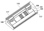
図10は、本発明のステレオカメラ100内部の素子配置と空気流の関係をさらに詳しく説明する説明図である。図10はカバー部材115内のステレオカメラ100を示す斜視図であり、図11はステレオカメラ100の正面図である。図10および図11において、カバー部材115は透明にして表示しており、点線で示している。
FIG. 10 is an explanatory diagram illustrating the relationship between the element arrangement inside the
図10および図11に示すように、カバー部材115内のステレオカメラ101において、前部下部のスリット117から後部上部のスリット117へ空気流301が形成されており、放熱部120の上部に空気流301が流れる構造になっている。上記の空気流路301を設けたことで、例えば、前部下部のスリット117の面積に比較して、後部上部のスリット117の面積の方が大きくなるように配置して、空気流301の流速を上げることができる。または、ステレオカメラ101前面とカバー部材115の間隙を最大限広くすることで、空気流301の流量を増加させる等の効果を得ることが可能となり、効率的にステレオカメラ101を冷却し、内部の温度上昇を抑制することができる。
As shown in FIGS. 10 and 11, in the
図12は、意匠カバー115を除去したステレオカメラ101単体において、筺体105を透明にした場合の正面から見た内部構成を示している。
FIG. 12 shows the internal configuration of the
図12に示すように、画像処理基板108に設置された画像処理素子109は、イメージセンサ間方向において、上記イメージセンサ106より内側に配置されている。そのため、上記画像処理素子109の上方を通過する空気流301は、上記イメージセンサ106の上方を通過する空気流である303とは重複しないように形成されている。上記の素子配置とすることにより、上記筺体105に形成された放熱部120を通過する上記空気流301は、上記イメージセンサ106の上方を通過する空気流303とは分離される。
画像処理基板108に設置された画像処理素子109の消費電力は、イメージセンサ106の消費電力よりも大きく、ステレオカメラ101の高機能化に伴い、発熱量が大きくなっていく傾向にある。
As shown in FIG. 12, the
The power consumption of the
本実施例のステレオカメラでは、上記放熱部120を通過する空気流301と上記イメージセンサ106の上方を通過する空気流303とは分離されている。上記の構造とすることにより、画像処理素子109からの熱を、放熱部120を通して筺体105上面に逃がすと共に、イメージセンサ106の近傍を通過しない経路の空気流301で外部に放熱することで、イメージセンサ106の温度上昇も抑制できる。
In the stereo camera of this embodiment, the
以上述べた構造とすることにより、ステレオカメラ101内の画像処理素子109を効率的に冷却すると共に、複数の画像処理素子109の発熱によるイメージセンサ106の温度上昇への影響を低減することが可能なステレオカメラ101を提供することができる。
With the structure described above, it is possible to efficiently cool the
<第2の実施の形態>
図13は第2の実施例のステレオカメラ101の筺体105を透明にした場合の正面から見た内部構成を示している。筺体105は透明にして表示しており、点線で示している。
<Second Embodiment>
FIG. 13 shows the internal configuration of the
図13は図12で示した放熱部120の配置を、各素子の熱量が左右で均等になるように計算して調整、配置を行った実施例2のステレオカメラ101を示している。
FIG. 13 shows the
内部の画像処理素子109の発熱によるステレオカメラ101の左右の温度上昇が不均一であると、画像処理基板108の局所的な膨張による筺体の左右の変形量の差によってイメージセンサ106間の光軸ずれが起こり、検出される画像データが不正確になる等の恐れがある。従って、図13に示すように左右対称となる画像処理素子109および放熱部120の配置とすることにより、内部の画像処理素子109の発熱による左右の温度上昇の不均一が是正され、対称な変形となることで光軸ずれを低減してより正確なデータ取得を行うことが可能となる。
If the temperature rise on the left and right sides of the
<第3の実施の形態>
図14は第3の実施例のステレオカメラ101の斜視図を、図15は放熱部121の断面であるD−D‘断面図を示している。
<Third embodiment>
FIG. 14 shows a perspective view of the
図14の斜視図に示すように、第3の実施例におけるステレオカメラ101は、放熱部121が筺体105の背面まで延伸されている。
As shown in the perspective view of FIG. 14, in the
図15のD−D‘断面図に示すように、実施例1と同様に、カメラ筐体105の内部に内蔵された画像処理基板108上には、画像処理用素子109が複数搭載されており、伝熱部材110を介して放熱部121および筺体105に接続し、画像処理用素子109の熱が放熱される構造となっている。
As shown in the DD'cross-sectional view of FIG. 15, a plurality of
実施例3における放熱部121は、実施例1で述べた空気流301が放熱部121に沿って円滑に流れるように、放熱部121のフィンが筐体105の背面まで延伸されている構造となっている。上記の構造とすることにより、流路抵抗が低下し、空気流301の流速を増加させることが可能となる。従って、ステレオカメラ101の冷却効率を上げることができる。
The
<第4の実施の形態>
図16は、ステレオカメラ101の実施例1および実施例3における(a)放熱部120、121と実施例4における(b)放熱部122の上面図を示している。
<Fourth Embodiment>
FIG. 16 shows a top view of (a)
図16に示すように、実施例1および実施例3では、(a)放熱部120、121において、フロントガラス側とリアガラス側の幅が同じであるが、実施例4の(b)放熱部122では、リアガラス側の幅がフロントガラス側の幅よりも大きい末広がり型になっている。上記の放熱部122の構造とすることにより、流路抵抗が低下し、空気流301の流速を上げることが可能となる従って、ステレオカメラ101の冷却効率をさらに上げることができる。
As shown in FIG. 16, in the first and third embodiments, the widths of the windshield side and the rear glass side of the (a)
<第5の実施の形態>
図17は実施例5のステレオカメラ101の斜視図を、図18は筐体105の中央断面であるE−E‘断面図を示している。
<Fifth Embodiment>
FIG. 17 shows a perspective view of the
実施例5におけるステレオカメラ101においても、実施例1と同様に、筐体105の左右に一対のイメージセンサ106が設置されており、上記画像処理基板108は、上記イメージセンサ106の間に設置されていて、上記基板108上には、画像処理用素子109が複数搭載されている。
In the
実施例5における画像処理基板108においては、図18のE−E‘断面図に示すように、筺体105のフロントガラス対向面である傾斜面と画像処理基板108とが平行に配置されており、上記画像処理用素子109は、伝熱ゲルや伝熱シート等の伝熱部材110を介して、筺体105の上記傾斜面に直接接触する構造となっている。
In the
上記のような構造とすることで、実施例1に示したような放熱部120が無くても、上記画像処理109の熱が筺体105に伝熱し、上記空気流301に放熱される構造になっている。
With the above structure, even if the
また、筺体105に逃がした熱がイメージセンサ106に伝熱されると、イメージセンサ106の温度上昇を招く。そのため、上記の熱をイメージセンサ106に伝熱させない部材として、筺体105の中央部分と左右のイメージセンサ106の周囲部分を分離する断熱シート等の断熱部材112を図17に示す筺体105に設置している。上記の断熱部材112を設置することで、上記画像処理用素子109の熱が上記イメージセンサ106に伝熱することを防止して、イメージセンサ106の温度上昇を防止することが可能となる。
Further, when the heat released to the
<第6の実施の形態>
図19は、第6の実施例のステレオカメラ100のカバー部材125を示している。図19のカバー部材125は、フロントガラス対向面である上面部のみ、別部材の遮光部材127で形成するものである。図19はカバー部材125の斜視図、図20はカバー部材125中央のF−F‘断面図を示している。
<Sixth Embodiment>
FIG. 19 shows a
図19の斜視図に示すように、実施例6におけるカバー部材125は、上面のみ、別部材である遮光部材127で形成されていて、開口部126が設置されている。
As shown in the perspective view of FIG. 19, the
上述したように、夏場の炎天下に車両が駐車された場合には、フロントガラス上部近辺は、非常に高温になることが測定されており、そのような状況においては、日射熱からステレオカメラ101を守ることが、正常な稼動と信頼性の確保には重要となる。そのため、実施例6におけるカバー部材125においては、図20の断面図に示すように、断熱性の高い別部材で作成した遮光部材127を形成し、カバー部材125の上面部分に設置することで、日射熱からステレオカメラ101を効果的に守ることが可能となる。
As mentioned above, when the vehicle is parked under the scorching sun in the summer, it has been measured that the temperature near the upper part of the windshield becomes extremely high. Observing is important for ensuring normal operation and reliability. Therefore, in the
さらに、上記遮光部材127を上記カバー部材125に取り付ける際に、遮光部材127とステレオカメラ101の筐体105上面との距離を調節可能な位置調整機構128を設置して調整することで、冷却に最適な空気流301および302を設定することができ、ステレオカメラ101の温度上昇を効果的に低減することが可能となる。
Further, when the light-shielding
100…ステレオカメラおよびカバー部材、101…ステレオカメラ、102…車両、103…フロントガラス、115、125…カバー部材、105…筐体、106…イメージセンサ、108…画像処理基板、109…画像処理素子、110…伝熱部材、112…断熱部材、120、121、122…放熱部、116,126…開口部、117…スリット、127…遮光部材、128…位置調整機構、 200…遮光膜、300…車内空気、301、302、303…空気流 100 ... Stereo camera and cover member, 101 ... Stereo camera, 102 ... Vehicle, 103 ... Front glass, 115, 125 ... Cover member, 105 ... Housing, 106 ... Image sensor, 108 ... Image processing board, 109 ... Image processing element , 110 ... Heat transfer member, 112 ... Insulation member, 120, 121, 122 ... Heat dissipation part, 116, 126 ... Opening, 117 ... Slit, 127 ... Light-shielding member, 128 ... Position adjustment mechanism, 200 ... Light-shielding film, 300 ... Car air, 301, 302, 303 ... Air flow
Claims (13)
左右方向における前記イメージセンサ間に配置され、前記イメージセンサで撮影された画像信号に対する処理を行う画像処理素子と、
前記画像処理素子と前記イメージセンサとを内蔵する筐体と、
前記筐体の前記イメージセンサ間の領域に、前記イメージセンサ前方の撮像方向に向かって下方に傾斜するように形成された傾斜面と、
前記筐体を覆うように配置され、前記筐体の前記傾斜面と対向する部分が前記傾斜面に沿うように形成されたカバー部材と、
前記画像処理素子と熱的に接続されて前記筐体の前記傾斜面に配置され、前記筐体の傾斜面と前記カバー部材の内面とにより前記傾斜面に沿って前記イメージセンサの撮像方向に延在するように画定された空気流路に露出するように配置された放熱部と
を備え、
前記カバー部材は、前記筐体の前記傾斜面の前下方向端部の位置と後上方向端部の位置とに開口部を有することを特徴とするステレオカメラ。 An image pickup device, an image sensor of a pair arranged at the same height at intervals in the lateral direction,
Disposed between the image sensor in the left-right direction, and the row processing on captured image signals by an image sensor weather image processing device,
A housing having a built-in with the image sensor and the image processing device,
The area between the image sensor of the housing, and an inclined surface formed so as to be inclined downward toward the imaging direction of the image sensor front,
A cover member arranged so as to cover the housing and formed so that a portion of the housing facing the inclined surface is formed along the inclined surface.
It is thermally connected to the image processing element and arranged on the inclined surface of the housing, and extends in the imaging direction of the image sensor along the inclined surface by the inclined surface of the housing and the inner surface of the cover member. and placed by the heat radiating portion so as to be exposed to the air flow path defined as resident
Equipped with a,
The cover member is a stereo camera having openings at the positions of the front-lower end and the rear-up end of the inclined surface of the housing.
Priority Applications (3)
| Application Number | Priority Date | Filing Date | Title |
|---|---|---|---|
| JP2017000967A JP6838262B2 (en) | 2017-01-06 | 2017-01-06 | Stereo camera |
| PCT/JP2017/045873 WO2018128083A1 (en) | 2017-01-06 | 2017-12-21 | Stereo camera |
| US16/470,639 US11019324B2 (en) | 2017-01-06 | 2017-12-21 | Stereo camera |
Applications Claiming Priority (1)
| Application Number | Priority Date | Filing Date | Title |
|---|---|---|---|
| JP2017000967A JP6838262B2 (en) | 2017-01-06 | 2017-01-06 | Stereo camera |
Publications (2)
| Publication Number | Publication Date |
|---|---|
| JP2018109724A JP2018109724A (en) | 2018-07-12 |
| JP6838262B2 true JP6838262B2 (en) | 2021-03-03 |
Family
ID=62791056
Family Applications (1)
| Application Number | Title | Priority Date | Filing Date |
|---|---|---|---|
| JP2017000967A Active JP6838262B2 (en) | 2017-01-06 | 2017-01-06 | Stereo camera |
Country Status (3)
| Country | Link |
|---|---|
| US (1) | US11019324B2 (en) |
| JP (1) | JP6838262B2 (en) |
| WO (1) | WO2018128083A1 (en) |
Families Citing this family (19)
| Publication number | Priority date | Publication date | Assignee | Title |
|---|---|---|---|---|
| JP6622332B2 (en) * | 2018-02-13 | 2019-12-18 | 株式会社Subaru | Outside monitoring device |
| JP1610727S (en) | 2018-03-21 | 2018-08-06 | ||
| JP1610726S (en) * | 2018-03-21 | 2018-08-06 | ||
| JP1613901S (en) * | 2018-03-21 | 2018-09-18 | ||
| JP7208258B2 (en) * | 2018-12-05 | 2023-01-18 | 日立Astemo株式会社 | stereo camera |
| JP7154120B2 (en) * | 2018-12-11 | 2022-10-17 | 日立Astemo株式会社 | stereo camera device |
| USD908158S1 (en) * | 2019-01-07 | 2021-01-19 | Shenzhen Cnest Electronic Technology Co., Ltd. | Dashboard camera |
| JP7084328B2 (en) * | 2019-01-16 | 2022-06-14 | 日立Astemo株式会社 | Camera device |
| JP7234044B2 (en) * | 2019-06-12 | 2023-03-07 | 日立Astemo株式会社 | stereo camera |
| JP2022112529A (en) * | 2019-06-20 | 2022-08-03 | Agc株式会社 | Window glass for vehicle with information acquisition device |
| WO2021019349A1 (en) * | 2019-07-30 | 2021-02-04 | Ricoh Company, Ltd. | Capturing unit and vehicle control unit |
| CN114424514A (en) * | 2019-09-25 | 2022-04-29 | 三菱电机株式会社 | Vehicle-mounted camera |
| JP7467068B2 (en) * | 2019-10-23 | 2024-04-15 | キヤノン株式会社 | Imaging device |
| CN114616519A (en) * | 2019-11-07 | 2022-06-10 | 索尼半导体解决方案公司 | Image forming apparatus |
| US20230005976A1 (en) * | 2020-01-22 | 2023-01-05 | Hitachi Astemo, Ltd. | Imaging device |
| JP7326236B2 (en) | 2020-08-27 | 2023-08-15 | 本田技研工業株式会社 | moving body |
| JP2022067299A (en) | 2020-10-20 | 2022-05-06 | 株式会社デンソー | Imaging apparatus |
| CN112477814B (en) * | 2020-11-12 | 2022-08-23 | 新石器慧义知行智驰(北京)科技有限公司 | Defogging device and defogging method for unmanned in-vehicle sensor mirror surface |
| US20220239817A1 (en) * | 2021-01-22 | 2022-07-28 | Magna Electronics Inc. | Vehicular cooling system for forward camera module |
Family Cites Families (13)
| Publication number | Priority date | Publication date | Assignee | Title |
|---|---|---|---|---|
| JP3148749B1 (en) | 1999-09-22 | 2001-03-26 | 富士重工業株式会社 | In-vehicle camera |
| DE10329900A1 (en) * | 2003-07-03 | 2005-02-17 | Daimlerchrysler Ag | Camera system for a motor vehicle |
| JP2009100174A (en) * | 2007-10-16 | 2009-05-07 | Olympus Corp | Electronic imaging apparatus |
| JP5631116B2 (en) | 2010-08-24 | 2014-11-26 | キヤノン株式会社 | Imaging device |
| JP5829430B2 (en) * | 2011-05-20 | 2015-12-09 | 富士機械製造株式会社 | Imaging device |
| US9871971B2 (en) * | 2011-08-02 | 2018-01-16 | Magma Electronics Inc. | Vehicle vision system with light baffling system |
| JP2013190416A (en) * | 2012-02-13 | 2013-09-26 | Ricoh Co Ltd | Deposit detection device and in-vehicle equipment controller including the same |
| JP6052119B2 (en) * | 2013-09-19 | 2016-12-27 | 株式会社Jvcケンウッド | In-vehicle camera |
| US9352692B2 (en) * | 2014-03-10 | 2016-05-31 | Magna Mirrors Of America, Inc. | Vehicle vision system with camera and mirror mount |
| JP2016014564A (en) * | 2014-07-01 | 2016-01-28 | 株式会社リコー | Imaging unit |
| KR101724299B1 (en) * | 2015-02-04 | 2017-04-07 | 엘지전자 주식회사 | Triple camera |
| JP6308147B2 (en) * | 2015-03-05 | 2018-04-11 | トヨタ自動車株式会社 | In-vehicle sensor mounting structure |
| JP6361691B2 (en) * | 2016-05-17 | 2018-07-25 | トヨタ自動車株式会社 | Car camera |
-
2017
- 2017-01-06 JP JP2017000967A patent/JP6838262B2/en active Active
- 2017-12-21 WO PCT/JP2017/045873 patent/WO2018128083A1/en active Application Filing
- 2017-12-21 US US16/470,639 patent/US11019324B2/en active Active
Also Published As
| Publication number | Publication date |
|---|---|
| US11019324B2 (en) | 2021-05-25 |
| WO2018128083A1 (en) | 2018-07-12 |
| US20190320159A1 (en) | 2019-10-17 |
| JP2018109724A (en) | 2018-07-12 |
Similar Documents
| Publication | Publication Date | Title |
|---|---|---|
| JP6838262B2 (en) | Stereo camera | |
| JP6509256B2 (en) | Vehicle assistant system | |
| KR101724299B1 (en) | Triple camera | |
| JP6304205B2 (en) | In-vehicle imaging device | |
| JP6573713B2 (en) | In-vehicle image processing device | |
| JP4754284B2 (en) | Thermal insulation structure for in-vehicle equipment | |
| US7329869B2 (en) | Camera system | |
| US11485323B2 (en) | Imaging apparatus for vehicle | |
| JP6937923B2 (en) | In-vehicle camera device | |
| JP7101901B2 (en) | In-vehicle camera | |
| US20210001784A1 (en) | Vehicular windshield-mounted camera with heat dissipating glare shield | |
| JP5851009B2 (en) | In-vehicle camera mounting device | |
| WO2019220826A1 (en) | Camera device | |
| CN114286765B (en) | Roof module for forming a roof of a vehicle comprising a support module | |
| WO2022102209A1 (en) | Camera device | |
| JP7298750B2 (en) | In-vehicle camera | |
| US20230256916A1 (en) | Roof module having a transmitter and/or receiver apparatus | |
| JP7154120B2 (en) | stereo camera device | |
| JP2022112529A (en) | Window glass for vehicle with information acquisition device | |
| JP2020202522A (en) | Stereo camera |
Legal Events
| Date | Code | Title | Description |
|---|---|---|---|
| A621 | Written request for application examination |
Free format text: JAPANESE INTERMEDIATE CODE: A621 Effective date: 20190920 |
|
| A131 | Notification of reasons for refusal |
Free format text: JAPANESE INTERMEDIATE CODE: A131 Effective date: 20201124 |
|
| A521 | Request for written amendment filed |
Free format text: JAPANESE INTERMEDIATE CODE: A523 Effective date: 20201224 |
|
| TRDD | Decision of grant or rejection written | ||
| A01 | Written decision to grant a patent or to grant a registration (utility model) |
Free format text: JAPANESE INTERMEDIATE CODE: A01 Effective date: 20210119 |
|
| A61 | First payment of annual fees (during grant procedure) |
Free format text: JAPANESE INTERMEDIATE CODE: A61 Effective date: 20210122 |
|
| R150 | Certificate of patent or registration of utility model |
Ref document number: 6838262 Country of ref document: JP Free format text: JAPANESE INTERMEDIATE CODE: R150 |
|
| R250 | Receipt of annual fees |
Free format text: JAPANESE INTERMEDIATE CODE: R250 |