JP5074320B2 - Camera case - Google Patents
Camera case Download PDFInfo
- Publication number
- JP5074320B2 JP5074320B2 JP2008198267A JP2008198267A JP5074320B2 JP 5074320 B2 JP5074320 B2 JP 5074320B2 JP 2008198267 A JP2008198267 A JP 2008198267A JP 2008198267 A JP2008198267 A JP 2008198267A JP 5074320 B2 JP5074320 B2 JP 5074320B2
- Authority
- JP
- Japan
- Prior art keywords
- camera case
- air
- plate
- fan
- heat
- Prior art date
- Legal status (The legal status is an assumption and is not a legal conclusion. Google has not performed a legal analysis and makes no representation as to the accuracy of the status listed.)
- Active
Links
Images


Landscapes
- Cameras Adapted For Combination With Other Photographic Or Optical Apparatuses (AREA)
- Accessories Of Cameras (AREA)
- Studio Devices (AREA)
Description
本発明は、カメラケースに関わり、特に密閉型のカメラケースに収納した高感度撮像装置の冷却技術に関する。 The present invention relates to a camera case, and more particularly, to a cooling technique for a high-sensitivity imaging device housed in a sealed camera case.
EM−CCD( Electron Multiplying - Charge Coupled Device )等の高感度撮像素子を使用する撮像装置においては、高感度撮像素子の性能を最大限に引き出すため、外気温度が比較的に高い環境においても高感度撮像素子の温度を十分に低温に保つようにする必要がある。 In an imaging device using a high-sensitivity image sensor such as EM-CCD (Electron Multiplying-Charge Coupled Device), the sensitivity of the high-sensitivity image sensor is maximized. It is necessary to keep the temperature of the image sensor sufficiently low.
従来、監視用途等に用いられるテレビカメラ等の撮像装置の冷却構造では、高感度撮像素子冷却用のペルチェ素子の放熱部を撮像装置の筐体部に接触させることによって冷却する構造が主流であった。
しかし、撮像素子冷却用のペルチェ素子の放熱部を撮像装置の筐体部に接触させることによる冷却構造だけでは、冷却が必要な高感度撮像素子の内部温度及び電源部を低温に維持することが容易ではなく、冷却効果を充分に得ることができない場合が多かった。
Conventionally, in a cooling structure of an imaging device such as a television camera used for surveillance applications, a structure in which cooling is performed by bringing a heat dissipation part of a Peltier element for cooling a high-sensitivity imaging element into contact with a housing part of the imaging apparatus has been mainstream. It was.
However, it is possible to maintain the internal temperature of the high-sensitivity image sensor that requires cooling and the power supply unit at a low temperature only by the cooling structure by bringing the heat radiating part of the Peltier element for cooling the image sensor into contact with the housing unit of the image pickup apparatus. In many cases, it was not easy to obtain a sufficient cooling effect.
そこで本出願人は、特許文献1に開示されたように、撮像素子や電源で発生する熱をカメラケース内部で対流させ空気循環させる手段を備えた冷却構造を提案した。
特許文献1に開示された冷却構造は、ファンと放熱フィンとの間にダクトを設置しており、ファンからの冷却風を、ダクト内を通過させて整流し、放熱フィンに当てることにより冷却効果を得ている。
また、特許文献1に開示された冷却構造は、放熱フィンから上方に流れ出た温風をガイド板によって撮像装置のレンズ部の上部面の空間を通過させて撮像装置の前方に誘導している。この上部からの温風と、放熱フィンから下方に流れ出てレンズ部の下部面の空間を通過した温風とがカメラケースの前面ガラス付近で衝突する。そして、上下方向から衝突して合流した風は、レンズ部の左右側面に逃れて後方に向かって流れる。この後方に流れてきた風は、後部にあるファンの吸入口にフィードバックし、再び循環されるものである。また、カメラケースの前面ガラス付近には、高温の空気が流れることから、前面ガラスに対する加熱効果があるため、結露対策のためのデフロスターを不要とすることができたものである。
Therefore, as disclosed in Patent Document 1, the present applicant has proposed a cooling structure provided with a means for convection of air generated in the imaging device and the power source to circulate air inside the camera case.
In the cooling structure disclosed in Patent Document 1, a duct is installed between the fan and the heat radiating fin. The cooling air from the fan is rectified by passing through the duct and applied to the heat radiating fin. Have gained.
The cooling structure disclosed in Patent Document 1 guides the warm air flowing upward from the heat radiating fins to the front of the imaging device through the space on the upper surface of the lens unit of the imaging device by the guide plate. The warm air from the upper part and the warm air that flows downward from the radiation fins and passes through the space on the lower surface of the lens unit collide near the front glass of the camera case. And the wind which collided and merged from the up-down direction escapes to the right and left side surfaces of a lens part, and flows back. The wind that flows backward is fed back to the suction port of the fan at the rear and circulated again. Further, since high-temperature air flows in the vicinity of the front glass of the camera case, there is a heating effect on the front glass, so that it is possible to eliminate the need for a defroster as a countermeasure against condensation.
上述のカメラケースでは、ダクトの占める容積割合が大きく、撮像装置を収納するカメラケースを小型化するための障害となっていた。
また、ガイド板によって空気流を誘導する構造は、左右側面方向に開放された構成になっているため、空気の流れが一部分散してしまい、高温の空気の一部が前面ガラス方向に流れない。このため、高温の空気が十分に冷却されていない状態でファン側に流れ込んでフィードバックしてしまうことがあり、十分な冷却効果を得ることができなくなってしまう。
更に、前面ガラスに対する空気流が弱くなり、前面ガラスの結露防止効果があまり期待できなくなる。
本発明は上記課題に着目してなされたものであり、十分な冷却と小型化が可能で、更に前面ガラスの結露防止を実現することができるカメラケースの冷却構造を提供することを目的としている。
In the camera case described above, the volume ratio occupied by the duct is large, which has been an obstacle to downsizing the camera case that houses the imaging device.
In addition, the structure in which the air flow is guided by the guide plate is configured to be open in the left and right side directions, so the air flow is partially dispersed, and a part of the hot air does not flow in the direction of the front glass. . For this reason, in a state where the high-temperature air is not sufficiently cooled, it may flow into the fan side and feed back, so that a sufficient cooling effect cannot be obtained.
Furthermore, the air flow with respect to the front glass becomes weak, and the dew condensation preventing effect of the front glass cannot be expected so much.
The present invention has been made paying attention to the above-mentioned problems, and has an object to provide a cooling structure for a camera case that can be sufficiently cooled and downsized, and can further prevent dew condensation on the front glass. .
上記目的を達成するために、本発明のカメラケースは、撮像装置を収納する密閉型のカメラケースにおいて、前記撮像装置の撮像素子が発生する熱を放熱するための放熱フィンと、前記放熱フィンに空気流を吹き出すファンと、前記放熱フィンと前記ファンとの間に設けられ、前記ファンに対応する位置に複数の開口部を有する仕切板と、前記放熱フィンから流れる空気を流入し、所定の方向に吹き出すチャンバとを備えたものである。
また好ましくは、本発明のカメラケースにおいて、前記チャンバが吹き出す所定の方向は、前記カメラケースの前面方向である。
更に好ましくは、本発明のカメラケースは、内表面及び外表面の両方にフィン構造を有する。
In order to achieve the above object, a camera case of the present invention is a sealed camera case that houses an image pickup device, and includes a heat release fin for radiating heat generated by an image pickup device of the image pickup device, and the heat release fin. A fan that blows out an air flow; a partition plate that is provided between the heat dissipating fins and the fan and has a plurality of openings at positions corresponding to the fans; and air that flows from the heat dissipating fins flows in a predetermined direction And a chamber for blowing out.
Preferably, in the camera case of the present invention, the predetermined direction that the chamber blows out is a front direction of the camera case.
More preferably, the camera case of the present invention has a fin structure on both the inner surface and the outer surface.
本発明によれば、カメラケースの小型化を実現できる。
また、前面ガラスに対するデフロスタ装置が不要となり、カメラケースの部品点数を減らすことができ、製造コストも低減できる。
According to the present invention, the camera case can be downsized.
Further, the defroster device for the front glass is not required, the number of parts of the camera case can be reduced, and the manufacturing cost can be reduced.
以下、本発明によるカメラケースの冷却構造について従来技術と比較しながら、図面を参照して説明する。なお、各図の説明において、共通な機能を有する構成要素には同一の参照番号を付し、できるだけ説明の重複を避けるため、説明を省略する。 Hereinafter, the cooling structure of the camera case according to the present invention will be described with reference to the drawings while comparing with the prior art. In the description of each drawing, components having common functions are denoted by the same reference numerals, and the description thereof is omitted to avoid duplication as much as possible.
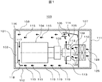
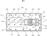
図1と図2によって従来のカメラケースの構成と冷却する空気の流れを説明する。図1は従来のカメラケースを側面から見た図で、図2は従来のカメラケースを上面から見た図である。説明のため、図1では、カメラケース外壁を形成する左側面板を除去し、図2では、カメラケース外壁を形成する上面板を除去している。100はカメラケース、101はカメラケース100の外壁を形成する前面板、102は前面板101の中央部に設けられた前面ガラス、103はカメラケース100の外壁を形成する上面板、112はカメラケース100の外壁を形成する底面板、111はカメラケース100の外壁を形成する背面板、120はカメラケース100の外壁を形成する右側面板、121はカメラケース100の外壁を形成する左側面板、104は撮像装置のレンズ部、108は撮像素子部、106は放熱フィン、105はガイド板、107は仕切板、109はダクト、110はファン、113〜119、122〜125、及び129は空気の流れを模式的に示す矢印である。
図1及び図2において、前面ガラス102は、撮像装置のレンズ部104を通して光像を入射するために、前面板101に中央部の開口部に取付けられている。また、前面板101、前面ガラス102、上面板103、底面板112、右側面板120、左側面板121、及び背面板111は、カメラケース100の外壁を構成して、密閉型のカメラケースとなっている。
図1及び図2においては、説明に不要な、例えば、カメラケース100の外壁の付属物(例えば、コネクタ、操作パネル、その他のアクセサリ)、等を省略している。カメラケース内部も同様で、例えば、撮像装置に必要な、映像信号処理部(CCD駆動回路、プロセス処理回路、制御回路、等)、電源部、等は省略している。なお、これらの図示しない部分は、従来例及び本発明のカメラケース100における空気の流れを妨げないように実装されている。
更に、仕切板107は、図1及び図2に示すように、撮像装置の上部及び下部ではファン110側に空気が流れないように仕切り、左右方向では、前面板101から流れる空気が背面板111側に流れ込むように仕切りが無い構造としている。また、図2では、図1に記載したガイド板105は省略し、記載していない。
The structure of a conventional camera case and the flow of cooling air will be described with reference to FIGS. FIG. 1 is a view of a conventional camera case as viewed from the side, and FIG. 2 is a view of the conventional camera case as viewed from above. For the sake of explanation, the left side plate that forms the outer wall of the camera case is removed in FIG. 1, and the upper surface plate that forms the outer wall of the camera case is removed in FIG.
1 and 2, the
In FIG. 1 and FIG. 2, for example, accessories (for example, connectors, operation panels, and other accessories) on the outer wall of the
Further, as shown in FIGS. 1 and 2, the
次に、従来のカメラケース100内部の冷却風の流れを図1及び図2を用いて説明する。
先ず図1において、ファン110は、カメラケース100の背面板111付近の空気を矢印125のように吸引し、矢印129のようにダクト109に吐き出す。ダクト109を通った空気は、矢印113のように、放熱フィン106の撮像素子部108側にぶつかって、上下方向に流れる。
放熱フィン106の撮像素子部108側には図示しないペルチェ素子が取り付けられており、撮像素子部108の発生する熱は、ペルチェ素子によって冷却され、ペルチェ素子はその冷却のために発熱する。ペルチェ素子の発生した熱は放熱フィン106の近傍を流れる空気の流れ(矢印113)にその熱量を吸収され冷却される。
Next, the flow of cooling air inside the
First, in FIG. 1, the
A Peltier element (not shown) is attached to the
ペルチェ素子から熱量を受け取った空気(矢印113)は、その後カメラケース100の上面側では、上方向に上昇する途中に設けられたガイド板105によって、曲げられ、背面から前面の方向に流れる(矢印115)。そして、前面板101に衝突し(矢印116)、下方の前面ガラス板102に向かう(矢印117)。
一方、ペルチェ素子から熱量を受け取った空気(矢印113)の一部はその後、カメラケース100の下面側では、底面板112に沿って背面から前面の方向に流れる(矢印119)。そして、前面板101に衝突し上方の前面ガラス板102に向かう(矢印118)。この間空気はカメラケース100内部より外気温が低いため冷却され、熱量を奪われていく。
After receiving heat from the Peltier element, the air (arrow 113) is bent on the upper surface side of the
On the other hand, a part of the air (arrow 113) that has received the amount of heat from the Peltier element then flows from the back surface to the front surface along the
次に、図2において、前面ガラス102に至った空気(矢印117、118)は、更に、前面ガラス102に熱量を奪われて冷却され、カメラケース100の側面側を、右側面板120及び左側面板121に沿って流れる(矢印123)。そしてこの冷却された空気は、両側面板120及び121によって更に熱量を奪われ、冷却されながら背面板111側に至る(矢印124)。背面板111側においては、ファン110が背面板111側の空気を吸引し(矢印125)、再度、カメラケース100内を循環して冷却がなされる。
なお、図1、図2に示すように、放熱フィン106のフィンは上下方向に複数の薄板状の金属(例えば、アルミニウム)板が平行に並ぶ構成で、放熱フィン106内に入った空気は上下に排出される(矢印113)構造である。
Next, in FIG. 2, the air (
As shown in FIGS. 1 and 2, the fins of the
次に、図3と図4によって、従来の冷却構造と本発明の一実施例の冷却構造の詳細を説明する。
図3(a)は、図1のダクト109、仕切板107、及びガイド板105の詳細を説明するため、図1と同様に示した部分拡大図(側面図)で、図3(b)は、本発明の一実施例の仕切板とガイド板の詳細を説明するための部分拡大図(側面図)である。
また、図4(a)は図3(a)の分解斜視図、図4(b)は図3(b)の分解斜視図である。126と326はフィンカバー、127はダクトパッキン、327はクッション、128は仕切板107の開口部、328は仕切板307の開口部、306は放熱フィンである。
フィンカバー326、クッション327、及び仕切板307は、例えば、それぞれの開口部の位置が一致するように組み付けられる。仕切板307の背面側には、開口部328に対応する位置にファン310の吹き出し口となるように設置される。ファン310は、例えば、DCファン(山洋電気製、SanAce40L )を並列に2つ組み合わせたものである。
Next, the details of the conventional cooling structure and the cooling structure of one embodiment of the present invention will be described with reference to FIGS.
3A is a partially enlarged view (side view) shown in the same manner as FIG. 1 in order to explain details of the
4 (a) is an exploded perspective view of FIG. 3 (a), and FIG. 4 (b) is an exploded perspective view of FIG. 3 (b). 126 and 326 are fin covers, 127 is a duct packing, 327 is a cushion, 128 is an opening of the
The
図3及び図4に示すように、本発明のカメラケースでは、ダクト109を除去してファン310と放熱フィン306間の距離を短くした構成としてカメラケースの長さを縮め容積を小さくした。また、距離が短く、風量が少なくできたことにより従来よりパワーの小さいファン310を採用できた。
また、仕切板107の開口部128は、ファン110から吸入されダクト109を介して放熱フィン106に至る空気を通すためのものであって、従来は1つの穴で構成された開口部であった。しかし、本発明では、開口部328を複数に分離し、分離された境界としての梁を設けた。これによって、梁によって乱気流を意図的に発生させるようにした。
また更に、従来のガイド板105と放熱フィン106に替え、本発明はチャンバ305と放熱フィン306を設けた。これによって、従来は、放熱フィン106を通過後上方に向かう空気の流れはガイド板105によって流れる方向の制御を受けていたところを、本発明では、放熱フィン306から吹き出された空気は、一旦チャンバ305に流入する。そして、チャンバ305は、流入された空気を一旦溜めるようにし、かつ吸入口の大きさより排出口の大きさを小さくしたノズル状にしたものである。この結果、カメラケースの上面板603側を流れる空気は、吹き出し速度が速くなり(流速が上がり)、カメラケース前面板101及び前面ガラス102に吹き付けることができ、冷却効率が向上する。
なお、フィンカバー326には、開口部を有する枠状の弾性部材で構成されたクッション327が取り付けられる。クッション327は、例えば、ゴムのような弾性体からなり、フィンカバー326と仕切板307の間で振動や衝撃を吸収する。
As shown in FIGS. 3 and 4, in the camera case of the present invention, the
Further, the
Furthermore, in place of the
Note that a
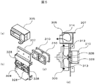
図5によって、本発明の冷却部分の一実施例の構成を更に詳細に説明する。図5は、本発明の冷却部分の構成を説明するための分解斜視図である。
図5(a)は図4(b)に示したチャンバ305、図5(b)は図4(b)の仕切板307、図5(c)は図4(b)のファン310、図5(d)は仕切板307、放熱フィン306、チャンバ305、ファン310を組み立てた断面図である。
図5(b)に示すように、4つの開口部328が縦と横に十字状に組合せた梁で分けられている。図5(c)に示すように、本発明の一実施例のファン310は横方向に隣接して2台設けられ、仕切板307の開口部328と吹き出し口とが一致するように、若しくはファン310から出力される空気がすべて開口部328から放熱フィン306に流れ込むように設けられる。即ち、ファン310の出力口は、仕切板307に密着して開口部328及び開口部328を構成する梁と相対し、更に、クッション327、及びフィンカバー326によってファン310から出力される空気が他へ漏れ出ないように構成する。
この結果、ファン310は、背面側の空気吸入口(図示せず)から空気を取り込み、仕切板307の開口部328、クッション327の開口部、及びフィンカバー326の開口部をそれぞれ通って、放熱フィン306に対して冷却風を吹き付ける。ファン310から出力された空気は、放熱フィン306に図5(d)に示す矢印313のように流れ込む。そして、放熱フィン306を冷却した空気は、放熱フィン306から熱を受け取り、上下方向に排出される。上方に排出された空気は、更に、チャンバ305に流れ込み、図5(d)に示す矢印314のように流れ、チャンバ305からカメラケースの前面側に向かって出力される。
この時、チャンバ305は、内部に流入した空気を溜める空間が形成されており、空気吸入口の断面積に比べ空気流出口(吹き出し口)の断面積を小さくし、流入する空気より吹き出す空気の流速を早くするようにしている。その結果、チャンバ305は、放熱フィン306から流入した空気を内部空間に一時的に溜めてから前方にノズル状に吹き出すことができる。
With reference to FIG. 5, the configuration of an embodiment of the cooling portion of the present invention will be described in more detail. FIG. 5 is an exploded perspective view for explaining the configuration of the cooling portion of the present invention.
5A is the
As shown in FIG. 5 (b), the four
As a result, the
At this time, the
次に、図6と図7によって本発明のカメラケースの構成と冷却する空気の流れを説明する。図6は本発明のカメラケースの一実施例を側面から見た図で、図7は本発明のカメラケースの一実施例を上面から見た図である。説明を分かり易くするため、図6では、カメラケース外壁を形成する左側面板を除去し、図7では、カメラケース外壁を形成する上面板を除去している。また、図7のチャンバ305もまた、上部の壁を除去して図示している。更に、組立等に用いる突起や金具等もできるだけ省略した。600はカメラケース、603はカメラケース600の外壁を形成する上面板、612はカメラケース600の外壁を形成する底面板、620はカメラケース600の外壁を形成する右側面板、621はカメラケース600の外壁を形成する左側面板、313、314、615〜619、及び622〜625は空気の流れを模式的に示す矢印である。
また、図6及び図7は、図1及び図2と同様に、前面板101、前面ガラス102、上面板603、底面板612、右側面板620、左側面板621、及び背面板111は、カメラケース600の外壁を構成した密閉型のカメラケースである。従って、カメラケース600の内部の空気は外部に漏れず、外部雰囲気もカメラケース600の内部には入らない。
また更に、図1と図2と同様に、図6及び図7においては、本発明の説明に不要な、例えば、カメラケース外壁の付属物(例えば、コネクタ、操作パネル、その他のアクセサリ)、等を省略している。カメラケース内部も同様で、例えば、撮像装置に必要な、映像信号処理部(CCD駆動回路、プロセス処理回路、制御回路、等)、電源部、等は省略している。なお、これらの図示しない部分は、従来例及び本発明のカメラケースにおける空気の流れを妨げないように実装されている。
Next, the configuration of the camera case of the present invention and the flow of cooling air will be described with reference to FIGS. FIG. 6 is a side view of one embodiment of the camera case of the present invention, and FIG. 7 is a top view of one embodiment of the camera case of the present invention. For easy understanding, the left side plate that forms the outer wall of the camera case is removed in FIG. 6, and the upper surface plate that forms the outer wall of the camera case is removed in FIG. The
6 and 7 are similar to FIGS. 1 and 2, the
Further, as in FIGS. 1 and 2, in FIGS. 6 and 7, there is no need to explain the present invention, for example, accessories on the outer wall of the camera case (for example, connectors, operation panels, other accessories), etc. Is omitted. The same applies to the inside of the camera case. For example, a video signal processing unit (CCD drive circuit, process processing circuit, control circuit, etc.), power supply unit, and the like necessary for the imaging apparatus are omitted. In addition, these parts which are not shown in figure are mounted so that the flow of air in a prior art example and the camera case of this invention may not be prevented.
本発明のカメラケース600内部の冷却風の流れを図6及び図7を用いて説明する。
先ず図6において、ファン310は、カメラケース600の背面板111付近の空気を矢印625のように吸引し、仕切板307の開口部328からクッション327を介して、放熱フィン306に吐き出す。放熱フィン306に入った空気は、矢印313のように、乱流となって放熱フィン306の撮像素子部108側にぶつかって、上下方向に流れる。
放熱フィン306の撮像素子部108側には図示しないペルチェ素子が取り付けられており、撮像素子108の発生する熱は、ペルチェ素子によって冷却され、ペルチェ素子はその冷却のために発熱する。ペルチェ素子の発生した熱は放熱フィン306の近傍を流れる空気の流れ(矢印313)にその熱量を吸収され冷却される。
The flow of the cooling air inside the
First, in FIG. 6, the
A Peltier element (not shown) is attached to the radiating
ペルチェ素子から熱量を受け取った空気(矢印313)は、その後カメラケース600の上面側では、チャンバ305に流入し、上方向から水平方向に流れの方向を変えられ、かつ、流速を増した空気(矢印615)となって、チャンバ305から前面方向に吐き出される。そして、前面板101に衝突し(矢印616)、下方の前面ガラス板102に向かう(矢印617)。
一方、ペルチェ素子から熱量を受け取った空気(矢印313)の一部はその後、カメラケース600の下面側では、底面板612に沿って背面から前面の方向に流れる(矢印619)。そして、前面板101に衝突し上方の前面ガラス板102に向かう(矢印618)。この間空気はカメラケース600内部より外気温が低いため冷却され、熱量を奪われていく。
The air (arrow 313) that has received the amount of heat from the Peltier element then flows into the
On the other hand, a part of the air (arrow 313) that has received the amount of heat from the Peltier element then flows from the back surface to the front surface along the
次に、図7において、前面ガラス102に至った空気(矢印617、618)は、更に、前面ガラス102に熱量を奪われて冷却され、カメラケース600の側面側を、右側面板620及び左側面板621に沿って流れる(矢印623)。そしてこの冷却された空気は、両側面板620及び621によって更に熱量を奪われ、冷却されながら背面板111側に至る(矢印624)。背面板111側においては、ファン310が背面板111側の空気を吸引し(矢印625)、再度、カメラケース600内を循環して冷却が継続して実行される。
Next, in FIG. 7, the air (
なお、図6及び図7に示すように、放熱フィン106のフィンは上下方向に複数の薄板状の金属(例えば、アルミニウム)板が平行に並ぶ構成で、放熱フィン306内に入った空気は上下に排出される(矢印313)構造である。
また、チャンバ305内、及び放熱フィン306内、等、カメラケース600内の空気の流れを示す矢印は、模式的に示した一実施例であり、この矢印以外の流れも存在することは自明である。
また、仕切板307の開口部の数は上記実施例では4つであったが、複数の開口部によって空気の乱流を発生させる梁状若しくは他の形状の障害物が形成されていれば良い。また、開口部の形状及び梁等の障害物の形状も任意である。また左右上下対称である必要いもない。
また、ファンの数もいくつでも良い。
As shown in FIGS. 6 and 7, the fins of the
In addition, the arrows indicating the air flow in the
Moreover, although the number of openings of the
Also, any number of fans is acceptable.
上記実施例1によれば、比較的大きな容積を必要とするダクトを不要としたことにより、ダクト分の占有容積を削減でき、カメラケースの小型化を実現できる。
そして、ダクトを除去したことによって、放熱フィンとファンとの間の間隔が小さくできたことにより、発生する圧力損失による風量の減少を抑制でき、また更に、放熱フィンとファンとの間に設置する仕切板に複数の開口部を設けたことにより開口部間に梁状部が形成され、この結果、ファンから送風された空気は、梁に当たって乱気流が発生することから、良好な空気流通状態を維持することができる。
更に、放熱部材から流入した空気をためて、所定の方向に吹き出すためのチャンバを備えた結果、空気流の分散を防止でき、かつ空気の流速を上げることができることから、十分な冷却効果を得ることが可能になる。
また、前面ガラスに対して良好な結露防止効果が得られるので、デフロスタ装置が不要となり、カメラケースの部品点数を減らすことができ、製造コストも低減できる。
According to the first embodiment, by eliminating the need for a duct that requires a relatively large volume, the occupied volume of the duct can be reduced, and the camera case can be downsized.
And, by removing the duct, the space between the radiating fin and the fan can be reduced, so that the reduction of the air volume due to the generated pressure loss can be suppressed, and furthermore, it is installed between the radiating fin and the fan. By providing a plurality of openings in the partition plate, a beam-like part is formed between the openings. As a result, air blown from the fan hits the beam and generates turbulent airflow, thus maintaining a good air flow state. can do.
Furthermore, as a result of providing a chamber for collecting the air flowing in from the heat radiating member and blowing it out in a predetermined direction, the air flow can be prevented from being dispersed and the air flow rate can be increased, thereby obtaining a sufficient cooling effect. It becomes possible.
In addition, since a good dew condensation prevention effect is obtained for the front glass, a defroster device is not required, the number of parts of the camera case can be reduced, and the manufacturing cost can be reduced.
次に、上記本発明の一実施形態のカメラケースでは、小型化を実現した。このため、カメラケース外壁を形成する板面の面積が小さくなる。このため、内部を流れる空気と外気との熱交換のための接触面積が小さくなり放熱効果が小さくなる。そこで、以下の図8に説明する実施例により放熱効果を向上した。
図8は、従来のカメラケースの外壁の形状と本発明の一実施例の外壁の形状を説明するための図である。図8(a)は従来のカメラケースの外壁を説明するための図で、図8(b)は本発明の一実施例のカメラケースの外壁を説明するための図である。図8(a)、(b)共に、左が断面図で右が斜視図である。また、カメラケースの前面板101、前面ガラス102、背面板、及びカメラケースの内部の構成物は図示していない。
図8で分かるように、従来のカメラケース100では、上面板103に放熱フィンを設けている構成となっている。従って、放熱は主に上面板側で効率が良い。本発明のカメラケース600では、上面板603の他に、更に、下面板612、右側面板620、及び左側面板621にも放熱用のフィンを設けた。このため、小型化したために、カメラケース外面の表面積が減少せず、従来と同等若しくはそれ以上の表面積とすることができる。
この結果、カメラケースの上下面及び左右側面でも放熱効果が向上する。
また、フィン形状は内表面側と外表面側の両面としたため、更に表面積が増し、効果的な冷却作用を維持することができる。
Next, the camera case according to the embodiment of the present invention described above is downsized. For this reason, the area of the board surface which forms a camera case outer wall becomes small. For this reason, the contact area for heat exchange between the air flowing inside and the outside air is reduced, and the heat dissipation effect is reduced. Therefore, the heat radiation effect was improved by the embodiment described in FIG. 8 below.
FIG. 8 is a view for explaining the shape of the outer wall of a conventional camera case and the shape of the outer wall of one embodiment of the present invention. FIG. 8A is a view for explaining the outer wall of a conventional camera case, and FIG. 8B is a view for explaining the outer wall of the camera case of one embodiment of the present invention. 8A and 8B, the left is a sectional view and the right is a perspective view. Further, the
As can be seen from FIG. 8, the
As a result, the heat dissipation effect is improved also on the upper and lower surfaces and the left and right side surfaces of the camera case.
Further, since the fin shape is both the inner surface side and the outer surface side, the surface area is further increased, and an effective cooling action can be maintained.
以上、本発明による撮像装置の冷却構造を実施例に基づいて説明してきたが、本発明は上記実施例に限定されず、本発明の趣旨を逸脱しない範囲において種々の変更が可能である。
例えば、、クッション327を構成する材料はゴムに限定されず、プラスチックやスプリング部材等にしてもよい。
また、仕切板307に形成する複数の開口部の数量および形状は本実施例に限定されず、所定の乱気流が得られる限りどのような形態であってもかまわない。例えば、梁は十字状である必要はなく、格子状、ハニカム状、等、任意の形状で良い。また、開口部の形状も同様に任意の形状で良い。
また、ファン310の型式及び設置個数は、本実施例に限定されるものではない。さらに、上記実施例のファン310は、並列に並べているが、直列に接続しても良い。
また、チャンバ305における空気を溜めるための内部空間の形状も、矩形状、球形状、断面長円状、等、任意で良い。また、複数の内部空間を形成してもよい。
また、本実施例ではカメラケースの内表面および外表面の両方にフィン構造を設けているが、カメラケースの内表面と外表面のいずれかのみにフィンを形成する構成にしてもよく、また、内表面及び外表面の一部分のみにフィンを形成する構成にしても良い。
As described above, the cooling structure of the imaging apparatus according to the present invention has been described based on the embodiments. However, the present invention is not limited to the above embodiments, and various modifications can be made without departing from the spirit of the present invention.
For example, the material constituting the
Further, the number and shape of the plurality of openings formed in the
Further, the type and the number of
Further, the shape of the internal space for storing air in the
In this embodiment, the fin structure is provided on both the inner surface and the outer surface of the camera case. However, the fin may be formed only on either the inner surface or the outer surface of the camera case. You may make it the structure which forms a fin only in a part of inner surface and outer surface.
上記実施例2によれば、小型化した本発明のカメラケースの場合には、カメラケース外壁を形成する板面の面積が小さくなる。このため、内部を流れる空気と外気との熱交換のための接触面積が小さくなり放熱効果が小さくなるが、カメラケース外壁を形成する上面板、下面板、及び両側面板の内表面及び外表面の両面をフィン構造とした。この結果、放熱のためのケース外壁全体の表面積を従来と同等とし、効果的な冷却作用を維持することができる。 According to the second embodiment, in the case of the downsized camera case of the present invention, the area of the plate surface forming the camera case outer wall is reduced. For this reason, the contact area for heat exchange between the air flowing inside and the outside air is reduced and the heat dissipation effect is reduced, but the inner surface and the outer surface of the upper surface plate, the lower surface plate, and both side surface plates that form the outer wall of the camera case are reduced. Both sides have a fin structure. As a result, the surface area of the entire case outer wall for heat radiation can be made equal to that of the conventional case, and an effective cooling action can be maintained.
100:カメラケース、 101:前面板、 102:前面ガラス、 103:上面板、 104:レンズ部、 105:ガイド板、 106:放熱フィン、 107:仕切板、 108:撮像素子部、 109:ダクト、 110:ファン、 111:背面板、 112:底面板、 113〜119、129:空気の流れを模式的に示す矢印、 120:右側面板、 121:左側面板、 122〜125:空気の流れを模式的に示す矢印、 126:フィンカバー、 127:ダクトパッキン、 128:開口部、 305:チャンバ、 306:放熱フィン、 307:仕切板、 310:ファン、 313、314:空気の流れを模式的に示す矢印、 326:フィンカバー、 327:クッション、 328:開口部、 600:カメラケース、 603:上面板、 612:底面板、 620:右側面板、 621:左側面板、 615〜619、622〜625:空気の流れを模式的に示す矢印。 DESCRIPTION OF SYMBOLS 100: Camera case 101: Front plate 102: Front glass 103: Top plate 104: Lens part 105: Guide plate 106: Radiation fin 107: Partition plate 108: Image sensor part 109: Duct 110: Fan, 111: Back plate, 112: Bottom plate, 113 to 119, 129: Arrows schematically showing air flow, 120: Right side plate, 121: Left side plate, 122 to 125: Typical air flow 126: Fin cover, 127: Duct packing, 128: Opening, 305: Chamber, 306: Radiation fin, 307: Partition plate, 310: Fan, 313, 314: Arrows schematically showing air flow 326: Fin cover, 327: Cushion, 328: Opening, 600: Camera case, 60 3: top plate, 612: bottom plate, 620: right side plate, 621: left side plate, 615-619, 622-625: arrows schematically showing the flow of air.
Claims (3)
前記撮像装置の撮像素子から発生する熱を放熱するための放熱フィンと、
前記放熱フィンに空気流を吹き出すファンと、
前記放熱フィンと前記ファンとの間に設けられ、前記ファンに対応する位置に複数の開口部を有する仕切板と、
前記放熱フィンから流れる空気を流入し、所定の方向に吹き出すチャンバと、
を備えたことを特徴とするカメラケース。 In a sealed camera case that houses the imaging device,
A heat dissipating fin for dissipating heat generated from the image pickup device of the image pickup device;
A fan that blows out airflow to the heat dissipating fins;
A partition plate provided between the radiating fin and the fan, and having a plurality of openings at positions corresponding to the fan;
A chamber that inflows air flowing from the heat dissipating fins and blows out in a predetermined direction;
A camera case characterized by comprising
Priority Applications (1)
| Application Number | Priority Date | Filing Date | Title |
|---|---|---|---|
| JP2008198267A JP5074320B2 (en) | 2008-07-31 | 2008-07-31 | Camera case |
Applications Claiming Priority (1)
| Application Number | Priority Date | Filing Date | Title |
|---|---|---|---|
| JP2008198267A JP5074320B2 (en) | 2008-07-31 | 2008-07-31 | Camera case |
Publications (3)
| Publication Number | Publication Date |
|---|---|
| JP2010041085A JP2010041085A (en) | 2010-02-18 |
| JP2010041085A5 JP2010041085A5 (en) | 2011-09-01 |
| JP5074320B2 true JP5074320B2 (en) | 2012-11-14 |
Family
ID=42013217
Family Applications (1)
| Application Number | Title | Priority Date | Filing Date |
|---|---|---|---|
| JP2008198267A Active JP5074320B2 (en) | 2008-07-31 | 2008-07-31 | Camera case |
Country Status (1)
| Country | Link |
|---|---|
| JP (1) | JP5074320B2 (en) |
Families Citing this family (10)
| Publication number | Priority date | Publication date | Assignee | Title |
|---|---|---|---|---|
| JP5631116B2 (en) * | 2010-08-24 | 2014-11-26 | キヤノン株式会社 | Imaging device |
| JP6053396B2 (en) * | 2012-08-27 | 2016-12-27 | キヤノン株式会社 | Imaging device |
| CN102937771B (en) * | 2012-11-06 | 2015-09-09 | 浙江宇视科技有限公司 | A kind of heating of video camera and the device of heat radiation |
| WO2015025687A1 (en) * | 2013-08-19 | 2015-02-26 | 株式会社日立国際電気 | Electronic device |
| JP6376789B2 (en) * | 2014-03-20 | 2018-08-22 | キヤノン株式会社 | Imaging device |
| JP6187442B2 (en) * | 2014-12-11 | 2017-08-30 | 東レ株式会社 | Camera housing and imaging method |
| JP6419598B2 (en) * | 2015-02-16 | 2018-11-07 | 株式会社日立国際電気 | Camera device and method for preventing condensation of camera device |
| FR3048659B1 (en) * | 2016-03-10 | 2018-04-13 | Valeo Systemes D'essuyage | OPTICAL DETECTION SYSTEM FOR MOTOR VEHICLE |
| JP6401764B2 (en) * | 2016-10-20 | 2018-10-10 | 株式会社アマダホールディングス | Fire detection camera |
| JP7111910B2 (en) * | 2019-11-11 | 2022-08-02 | 株式会社日立国際電気 | Imaging device |
Family Cites Families (3)
| Publication number | Priority date | Publication date | Assignee | Title |
|---|---|---|---|---|
| JPH0359777A (en) * | 1989-07-28 | 1991-03-14 | Toshiba Corp | Image data edition system |
| JP4257317B2 (en) * | 2005-06-27 | 2009-04-22 | 富士通株式会社 | Imaging device |
| JP4954625B2 (en) * | 2006-07-20 | 2012-06-20 | 株式会社日立国際電気 | Surveillance camera |
-
2008
- 2008-07-31 JP JP2008198267A patent/JP5074320B2/en active Active
Also Published As
| Publication number | Publication date |
|---|---|
| JP2010041085A (en) | 2010-02-18 |
Similar Documents
| Publication | Publication Date | Title |
|---|---|---|
| JP5074320B2 (en) | Camera case | |
| CN110431925B (en) | Display device | |
| JP5150987B2 (en) | Projection display | |
| JP4480638B2 (en) | Through-flow forced air-cooled heat sink and projection display | |
| JP6215857B2 (en) | Air-cooled laser apparatus provided with an L-shaped heat conducting member having a radiation fin | |
| TWI405945B (en) | Air-cooling heat exchanger and electronic equipment employing same | |
| JP5611514B2 (en) | Outdoor unit | |
| JP4900558B2 (en) | Outdoor unit | |
| JP2010196926A (en) | Electric device for air conditioner | |
| JP2011061201A (en) | Radiator module | |
| JP5482780B2 (en) | Air conditioner outdoor unit | |
| JP5556288B2 (en) | Heat dissipation unit and electronic device using the same | |
| JP2010054168A (en) | Outdoor unit for air conditioner | |
| JP6387527B2 (en) | Air conditioner outdoor unit | |
| JP6594428B2 (en) | Air conditioner outdoor unit and air conditioner | |
| JP6145651B2 (en) | vending machine | |
| JP6818558B2 (en) | Outdoor unit of air conditioner | |
| JPH0613776A (en) | Cooling structure of electronic part | |
| JP6632733B2 (en) | Outdoor unit of air conditioner | |
| JP2009133531A (en) | Outdoor unit of air conditioner | |
| JP6156913B2 (en) | Electronic equipment | |
| JP4944420B2 (en) | Cooling structure for heat source in housing and projector | |
| JP2020180709A (en) | Outdoor unit of air conditioner | |
| CN211236548U (en) | Projector with a light source | |
| KR102270062B1 (en) | A cold air blower for agricultural purpose |
Legal Events
| Date | Code | Title | Description |
|---|---|---|---|
| A521 | Request for written amendment filed |
Free format text: JAPANESE INTERMEDIATE CODE: A523 Effective date: 20110715 |
|
| A621 | Written request for application examination |
Free format text: JAPANESE INTERMEDIATE CODE: A621 Effective date: 20110715 |
|
| A977 | Report on retrieval |
Free format text: JAPANESE INTERMEDIATE CODE: A971007 Effective date: 20120710 |
|
| TRDD | Decision of grant or rejection written | ||
| A01 | Written decision to grant a patent or to grant a registration (utility model) |
Free format text: JAPANESE INTERMEDIATE CODE: A01 Effective date: 20120807 |
|
| A01 | Written decision to grant a patent or to grant a registration (utility model) |
Free format text: JAPANESE INTERMEDIATE CODE: A01 |
|
| A61 | First payment of annual fees (during grant procedure) |
Free format text: JAPANESE INTERMEDIATE CODE: A61 Effective date: 20120823 |
|
| R150 | Certificate of patent or registration of utility model |
Ref document number: 5074320 Country of ref document: JP Free format text: JAPANESE INTERMEDIATE CODE: R150 Free format text: JAPANESE INTERMEDIATE CODE: R150 |
|
| FPAY | Renewal fee payment (event date is renewal date of database) |
Free format text: PAYMENT UNTIL: 20150831 Year of fee payment: 3 |
|
| R250 | Receipt of annual fees |
Free format text: JAPANESE INTERMEDIATE CODE: R250 |
|
| R250 | Receipt of annual fees |
Free format text: JAPANESE INTERMEDIATE CODE: R250 |
|
| R250 | Receipt of annual fees |
Free format text: JAPANESE INTERMEDIATE CODE: R250 |
|
| R250 | Receipt of annual fees |
Free format text: JAPANESE INTERMEDIATE CODE: R250 |
|
| R250 | Receipt of annual fees |
Free format text: JAPANESE INTERMEDIATE CODE: R250 |
|
| R250 | Receipt of annual fees |
Free format text: JAPANESE INTERMEDIATE CODE: R250 |
|
| R250 | Receipt of annual fees |
Free format text: JAPANESE INTERMEDIATE CODE: R250 |
|
| R250 | Receipt of annual fees |
Free format text: JAPANESE INTERMEDIATE CODE: R250 |
|
| R250 | Receipt of annual fees |
Free format text: JAPANESE INTERMEDIATE CODE: R250 |