RU2476740C2 - Transmission stage - Google Patents
Transmission stage Download PDFInfo
- Publication number
- RU2476740C2 RU2476740C2 RU2010119572/11A RU2010119572A RU2476740C2 RU 2476740 C2 RU2476740 C2 RU 2476740C2 RU 2010119572/11 A RU2010119572/11 A RU 2010119572/11A RU 2010119572 A RU2010119572 A RU 2010119572A RU 2476740 C2 RU2476740 C2 RU 2476740C2
- Authority
- RU
- Russia
- Prior art keywords
- driven
- gear stage
- drive
- transmission
- housing
- Prior art date
Links
- 230000005540 biological transmission Effects 0.000 title claims abstract description 77
- 230000033001 locomotion Effects 0.000 claims abstract description 18
- 230000007246 mechanism Effects 0.000 claims description 53
- 238000005096 rolling process Methods 0.000 claims description 29
- 230000001419 dependent effect Effects 0.000 claims description 2
- 230000000694 effects Effects 0.000 abstract description 2
- 239000007787 solid Substances 0.000 abstract 4
- 239000000126 substance Substances 0.000 abstract 1
- 230000009471 action Effects 0.000 description 3
- 230000006835 compression Effects 0.000 description 3
- 238000007906 compression Methods 0.000 description 3
- 238000000034 method Methods 0.000 description 3
- 230000008901 benefit Effects 0.000 description 2
- 238000013016 damping Methods 0.000 description 2
- 239000000463 material Substances 0.000 description 2
- 239000004033 plastic Substances 0.000 description 2
- 229920003023 plastic Polymers 0.000 description 2
- 230000000284 resting effect Effects 0.000 description 2
- 229910000831 Steel Inorganic materials 0.000 description 1
- 230000001133 acceleration Effects 0.000 description 1
- 238000007792 addition Methods 0.000 description 1
- 230000002730 additional effect Effects 0.000 description 1
- 238000005452 bending Methods 0.000 description 1
- 239000000919 ceramic Substances 0.000 description 1
- 230000008859 change Effects 0.000 description 1
- 238000006243 chemical reaction Methods 0.000 description 1
- 230000008878 coupling Effects 0.000 description 1
- 238000010168 coupling process Methods 0.000 description 1
- 238000005859 coupling reaction Methods 0.000 description 1
- 230000009365 direct transmission Effects 0.000 description 1
- 238000006073 displacement reaction Methods 0.000 description 1
- 238000005516 engineering process Methods 0.000 description 1
- 238000011031 large-scale manufacturing process Methods 0.000 description 1
- 239000000696 magnetic material Substances 0.000 description 1
- 239000002184 metal Substances 0.000 description 1
- 230000000737 periodic effect Effects 0.000 description 1
- 230000010363 phase shift Effects 0.000 description 1
- 238000003825 pressing Methods 0.000 description 1
- 230000008569 process Effects 0.000 description 1
- 230000003068 static effect Effects 0.000 description 1
- 239000010959 steel Substances 0.000 description 1
- 229920001169 thermoplastic Polymers 0.000 description 1
Images


Classifications
-
- B—PERFORMING OPERATIONS; TRANSPORTING
- B60—VEHICLES IN GENERAL
- B60N—SEATS SPECIALLY ADAPTED FOR VEHICLES; VEHICLE PASSENGER ACCOMMODATION NOT OTHERWISE PROVIDED FOR
- B60N2/00—Seats specially adapted for vehicles; Arrangement or mounting of seats in vehicles
- B60N2/02—Seats specially adapted for vehicles; Arrangement or mounting of seats in vehicles the seat or part thereof being movable, e.g. adjustable
- B60N2/0224—Non-manual adjustments, e.g. with electrical operation
- B60N2/02246—Electric motors therefor
- B60N2/02253—Electric motors therefor characterised by the transmission between the electric motor and the seat or seat parts
-
- B—PERFORMING OPERATIONS; TRANSPORTING
- B60—VEHICLES IN GENERAL
- B60N—SEATS SPECIALLY ADAPTED FOR VEHICLES; VEHICLE PASSENGER ACCOMMODATION NOT OTHERWISE PROVIDED FOR
- B60N2/00—Seats specially adapted for vehicles; Arrangement or mounting of seats in vehicles
- B60N2/02—Seats specially adapted for vehicles; Arrangement or mounting of seats in vehicles the seat or part thereof being movable, e.g. adjustable
- B60N2/22—Seats specially adapted for vehicles; Arrangement or mounting of seats in vehicles the seat or part thereof being movable, e.g. adjustable the back-rest being adjustable
- B60N2/225—Seats specially adapted for vehicles; Arrangement or mounting of seats in vehicles the seat or part thereof being movable, e.g. adjustable the back-rest being adjustable by cycloidal or planetary mechanisms
- B60N2/2252—Seats specially adapted for vehicles; Arrangement or mounting of seats in vehicles the seat or part thereof being movable, e.g. adjustable the back-rest being adjustable by cycloidal or planetary mechanisms in which the central axis of the gearing lies inside the periphery of an orbital gear, e.g. one gear without sun gear
-
- F—MECHANICAL ENGINEERING; LIGHTING; HEATING; WEAPONS; BLASTING
- F16—ENGINEERING ELEMENTS AND UNITS; GENERAL MEASURES FOR PRODUCING AND MAINTAINING EFFECTIVE FUNCTIONING OF MACHINES OR INSTALLATIONS; THERMAL INSULATION IN GENERAL
- F16H—GEARING
- F16H1/00—Toothed gearings for conveying rotary motion
- F16H1/28—Toothed gearings for conveying rotary motion with gears having orbital motion
- F16H1/32—Toothed gearings for conveying rotary motion with gears having orbital motion in which the central axis of the gearing lies inside the periphery of an orbital gear
-
- F—MECHANICAL ENGINEERING; LIGHTING; HEATING; WEAPONS; BLASTING
- F16—ENGINEERING ELEMENTS AND UNITS; GENERAL MEASURES FOR PRODUCING AND MAINTAINING EFFECTIVE FUNCTIONING OF MACHINES OR INSTALLATIONS; THERMAL INSULATION IN GENERAL
- F16H—GEARING
- F16H13/00—Gearing for conveying rotary motion with constant gear ratio by friction between rotary members
- F16H13/02—Gearing for conveying rotary motion with constant gear ratio by friction between rotary members without members having orbital motion
- F16H13/04—Gearing for conveying rotary motion with constant gear ratio by friction between rotary members without members having orbital motion with balls or with rollers acting in a similar manner
-
- F—MECHANICAL ENGINEERING; LIGHTING; HEATING; WEAPONS; BLASTING
- F16—ENGINEERING ELEMENTS AND UNITS; GENERAL MEASURES FOR PRODUCING AND MAINTAINING EFFECTIVE FUNCTIONING OF MACHINES OR INSTALLATIONS; THERMAL INSULATION IN GENERAL
- F16H—GEARING
- F16H13/00—Gearing for conveying rotary motion with constant gear ratio by friction between rotary members
- F16H13/10—Means for influencing the pressure between the members
- F16H13/12—Means for influencing the pressure between the members by magnetic forces
Landscapes
- Engineering & Computer Science (AREA)
- Mechanical Engineering (AREA)
- General Engineering & Computer Science (AREA)
- Aviation & Aerospace Engineering (AREA)
- Transportation (AREA)
- Chairs For Special Purposes, Such As Reclining Chairs (AREA)
- Gear Transmission (AREA)
- Transmission Devices (AREA)
- Seats For Vehicles (AREA)
- Retarders (AREA)
- Friction Gearing (AREA)
Abstract
Description
Изобретение относится к ступени передачи, в частности сиденья автомобиля, которая имеет признаки ограничительной части п.1 формулы.The invention relates to a transmission stage, in particular a car seat, which has the features of the restrictive part of claim 1 of the formula.
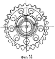
В электрических сервоприводах для регулятора положения сиденья известны ступени передачи, которые выполнены в виде ступени эксцентрика качения и которые находят свое применение в качестве ступени промежуточной передачи или приводных механизмов для создания вращающегося эксцентриситета для зубчатых передаточных ступеней. Такая известная ступень передачи, служащая в качестве приводного механизма второй ступени передачи с вращающимся эксцентриситетом, представлена на фиг.14.In electric servo drives for the seat position controller, transmission steps are known which are designed as a rolling eccentric stage and which find their application as an intermediate gear stage or drive mechanisms for creating a rotating eccentricity for gear transmission stages. Such a known gear stage serving as a drive mechanism of a second gear stage with rotating eccentricity is shown in FIG.
И хотя ожидаемые свойства таких ступеней эксцентрика качения, а точнее передаточное число в диапазоне от 1,5 до 7, при высоком коэффициенте полезного действия и незначительном уровне шума на практике достаточно хорошо реализованы, эта концепция имеет недостатки, которые можно компенсировать только с помощью сравнительно больших затрат. Эксцентриситет, который необходим для точного и равномерного обкатывания зубчатой малой шестерни в зубчатом колесе с внутренним зацеплением и величина которого должна, разумеется, оставаться, по возможности, постоянной, возникает в известных решениях за счет сочетания разных геометрий, например, у приводных шариков, которые на фиг.14 прижимают малую шестерню вверх, максимального ограничения этого движения - благодаря зубчатому зацеплению, пальцам ведомого элемента передачи в отверстиях шестерни или не показанному здесь упорному подшипнику между приводным механизмом и ведомым элементом передачи, а также минимальному ограничению, например, с помощью шаровой опоры. В результате относительно большое число образующих эксцентриситет конструктивных элементов за счет допусков, деформаций, зависящих от нагрузок, и внутренних напряжений создает, с точки зрения всех условий эксплуатации, действительно чувствительную и ненадежную систему, которую в условиях крупносерийного производства предположительно можно поднять на должный качественный уровень только с большими затратами.And although the expected properties of such stages of the eccentric rolling, or rather the gear ratio in the range from 1.5 to 7, with a high efficiency and low noise level are quite well implemented in practice, this concept has disadvantages that can only be compensated for by using relatively large costs. The eccentricity, which is necessary for the precise and uniform rolling of the small gear in the gear with internal gearing and the value of which should, of course, remain as constant as possible, arises in known solutions due to the combination of different geometries, for example, for drive balls, which Fig. 14 presses the small gear up, the maximum restriction of this movement is due to gearing, the fingers of the driven transmission element in the holes of the gear or the thrust bearing not shown here iku between the drive gear and the driven transmission member, and also the minimum restriction, for example, using a ball bearing. As a result, a relatively large number of structural elements forming eccentricity due to tolerances, deformations depending on loads, and internal stresses creates, from the point of view of all operating conditions, a truly sensitive and unreliable system, which in large-scale production can presumably be raised to the proper quality level only with great expense.
В качестве другого принципиального недостатка следует назвать то, что такой эксцентрик качения можно хорошо и просто представить в виде приводного механизма, работающего в плоскости и с одной единственной малой шестерней на фиг.14, радиальные усилия должны восприниматься на опоре пропорционально общей оси отработки, однако непосредственно и полностью от роторного подшипника, вращающегося с высоким числом оборотов, и там при возрастающей нагрузке приводят к возрастанию мощности потерь и тем самым к снижению коэффициента полезного действия при повышенной эксплуатационной нагрузке. Если, напротив, известным образом в плоскостях расположены друг над другом две, а в идеальном случае три, малые шестерни, то радиальные усилия могут взаимно упираться - однако это невозможно в представленной форме выполнения с помощью простого расположения одинаковых ступеней друг над другом, так как даже минимальные геометрические отличия задействованных конструктивных элементов приводят к принципиально разным передаточным числам и тем самым при более длительной эксплуатации к смещению по фазе ступеней передачи друг относительно друга или при принудительной синхронности - к напряжениям, а затем и к потерям.As another fundamental drawback, it should be mentioned that such a rolling eccentric can be well and simply represented as a drive mechanism operating in the plane and with one single small gear in Fig. 14, the radial forces must be perceived on the support in proportion to the general working axis, however, directly and completely from a rotary bearing rotating with a high number of revolutions, and there, with increasing load, they lead to an increase in the loss power and thereby to a decrease in the efficiency vii with increased operational load. If, on the contrary, in a known manner in the planes two, and in the ideal case three, small gears are located one above the other, then the radial forces can mutually abut - however, this is not possible in the presented form of execution by simply arranging the same steps on top of each other, since even minimal geometric differences of the involved structural elements lead to fundamentally different gear ratios and, therefore, during longer operation, to a phase shift of the transmission stages relative to each other ha or with forced synchronization - to stress, and then to losses.
Задачей изобретения является улучшенное выполнение ступени передачи указанного типа.The objective of the invention is an improved implementation of the transmission stage of the specified type.
Эта задача решается согласно изобретению с помощью ступени передачи, имеющей признаки п.1 формулы изобретения. Выгодные формы выполнения являются предметом зависимых пунктов формулы.This problem is solved according to the invention using a transmission step having the characteristics of claim 1 of the claims. Advantageous forms of execution are the subject of the dependent claims.
Приводной механизм и ведомый элемент передачи выполнены с возможностью вращения вокруг параллельных друг другу осей, которые смещены друг относительно друга на эксцентриситет. Приводной механизм и ведомый элемент передачи расположены в пространственном отношении друг в друге (соединены) и действуют с помощью обращенных друг к другу поверхностей. При этом приводной механизм можно расположить внутри ведомого элемента передачи (в этом случае приводной механизм действует с помощью своего внешнего контура, а ведомый элемент - с помощью своего внутреннего контура) или с точностью наоборот. Шарик или другое тело качения находится в клиновом зазоре, образованном по причине эксцентриситета между приводным механизмом и ведомым элементом, и способен двигаться, в частности продвигаться внутрь клинового зазора, и выдвигаться оттуда, причем это движение, как правило, происходит в плоскости перпендикулярно осям приводного механизма и ведомого элемента передачи.The drive mechanism and the driven element of the transmission are made to rotate around axes parallel to each other, which are offset from each other by eccentricity. The drive mechanism and the driven element of the transmission are spatially located in each other (connected) and operate using facing each other surfaces. In this case, the drive mechanism can be located inside the driven transmission element (in this case, the drive mechanism operates with its external circuit, and the driven element with its internal circuit) or exactly the opposite. The ball or other rolling body is located in the wedge gap, formed due to the eccentricity between the drive mechanism and the driven element, and is able to move, in particular, move into the wedge gap and move out from there, and this movement, as a rule, occurs in a plane perpendicular to the axes of the drive mechanism and transmission driven element.
Когда положение эксцентриситета относительно корпуса при этой первой, решающей для развития шумов ступени передачи неподвижно в пространстве, что преимущественно достигается за счет фиксированного, т.е. постоянного в пространстве, расположения приводного механизма и ведомого элемента передачи в одном общем корпусе, точки приложения силы постоянны в пространстве. С помощью этого предельно точного определения размера и направления эксцентриситета величина эксцентриситета во время вращения неизбежно остается точной, благодаря чему можно избежать периодических изменений соотношений нагрузок и развития шумов и вибраций по причине, в общем, стабильных антифрикционных свойств. С помощью такого устойчивого, с геометрической точки зрения, эксцентриситета между приводным механизмом и ведомым элементом передачи, точного, доступного расположения этих обоих конструктивных элементов друг относительно друга и использования шарика (или другого тела качения) в клиновом зазоре способствуют, во-первых, преобразованию при высоком коэффициенте полезного действия, а во-вторых, на ротор действует в качестве предварительного натяжения радиальная сила, пропорциональная соответствующему крутящему моменту, что при эксплуатации сводит к минимуму шумы.When the position of the eccentricity relative to the housing at this first, decisive for the development of noise stage of transmission is motionless in space, which is mainly achieved due to the fixed, i.e. constant in space, the location of the drive mechanism and the driven transmission element in one common housing, the points of application of force are constant in space. With this extremely accurate determination of the size and direction of the eccentricity, the magnitude of the eccentricity during rotation inevitably remains accurate, so that periodic changes in load ratios and the development of noise and vibration can be avoided due to, in general, stable antifriction properties. With the help of such a geometrically stable eccentricity between the drive mechanism and the driven transmission element, accurate, accessible arrangement of these two structural elements relative to each other and the use of the ball (or other rolling body) in the wedge gap, firstly, they transform during high efficiency, and secondly, a radial force proportional to the corresponding torque acts as a pre-tension on the rotor, which during operation ii minimizes noise.
Заявленная ступень передачи основывается на том же принципе, что и известная ступень передачи. Так можно регулировать передаточное отношение с помощью контуров на приводном механизме и/или ведомом элементе передачи, например, с помощью канавки, внутри которой бежит шарик. Заявленная ступень передачи улучшает свойства в отношении передаточного отношения, коэффициента полезного действия и бесшумности и предварительно натягивает желаемым образом ротор всегда в радиальном направлении, благодаря чему устраняются описанные недостатки, в частности исключается развитие шумов при электроприводах постоянного тока с роторами незначительной массы и незначительный коэффициент полезного действия высокоредуцирующей, одноступенчатой дифференцирующей передачи. Помимо основного принципа предлагается множество возможных дополнительных функций и дополнительных свойств, в частности различные возможности изменения передаточного числа и управления передаточным числом, а также простые решения для функций соединения, которые в общем контексте техники привода для сиденья могут привнести многочисленные выгоды. Для желаемого направления приведения в действие предусмотрено предпочтительно одно тело качения, например ролик, но также предпочтительно и шарик, для исключения статической неопределенности. Поскольку нужно только одно направление вращения приводного вала, необходим также только один единственный шарик или одно единственное тело качения.The declared transmission stage is based on the same principle as the known transmission stage. In this way, the gear ratio can be adjusted using the contours on the drive mechanism and / or the driven transmission element, for example, by means of a groove inside which the ball runs. The declared gear stage improves the properties with respect to gear ratio, efficiency and noiselessness and pre-pulls the rotor always in the radial direction in the desired way, thereby eliminating the described disadvantages, in particular, the development of noise in DC electric drives with rotors of low weight and low efficiency highly reducing, single-stage differentiating transmission. In addition to the basic principle, there are many possible additional functions and additional properties, in particular various options for changing the gear ratio and gear ratio control, as well as simple solutions for the coupling functions, which in the general context of the seat drive technology can bring numerous benefits. For the desired driving direction, preferably one rolling element is provided, for example a roller, but also preferably a ball, in order to eliminate static uncertainty. Since only one direction of rotation of the drive shaft is needed, only one single ball or one single rolling body is also needed.
Из патента FR 601.616 хотя и известна в принципе похожая на вид ступень передачи, однако тела качения распределены по всей окружности в виде планетарных элементов на стойке, которая при работе вращается, так что вращается и эксцентриситет.From FR 601.616, although a transmission stage similar in appearance is known in principle, the rolling elements are distributed around the entire circumference in the form of planetary elements on a rack, which rotates during operation, so that the eccentricity also rotates.
Заявленная ступень передачи применяется преимущественно в сервоприводе для сиденья автомобиля, например, в регуляторе наклона спинки, регуляторе высоты или регуляторе наклона. Сервопривод включает в себя приводной двигатель и заявленную ступень передачи и активизирует, например, нагружаемый передаточный механизм, как это раскрыто в DE 102004019466 B4, который представляет собой элемент подвижной структуры сиденья. Сервопривод может иметь, при необходимости, еще и вторую ступень передачи или другие ступени передачи, которые приданы в дополнение к первой ступени передачи и предвключены нагружаемому передаточному механизму. Нагружаемый передаточный механизм может выполнять вращательное движение или линейное движение или совмещать эти движения. Сервопривод может быть выполнен также как исполнительное устройство или может приводить последнее в действие, например, вращать тросиковый барабан, который наматывает тросик для деблокирования. Возможно также применение не только для сиденья автомобиля, но, например, для стеклоподъемников и регулируемых зеркал.The claimed gear stage is mainly used in the servo drive for the car seat, for example, in the backrest, height adjuster or tilt adjuster. The servo drive includes a drive motor and a declared gear stage and activates, for example, a load-bearing gear as disclosed in
Ниже изобретение описывается более подробно с помощью примера выполнения, представленного на чертеже, с дополнениями и вариациями.Below the invention is described in more detail using the exemplary embodiment shown in the drawing, with additions and variations.
Фиг.1: поперечное сечение первой ступени передачи, причем для наглядности обозначен только один шарик, а справа снаружи - изображение его радиальной нагрузки.Figure 1: a cross section of the first gear stage, and for clarity, only one ball is indicated, and the image of its radial load on the outside right.
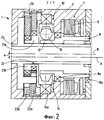
Фиг.2: продольное сечение сервопривода с приводным двигателем, первой ступенью передачи и второй ступенью передачи.Figure 2: a longitudinal section of a servo drive with a drive motor, a first gear stage and a second gear stage.
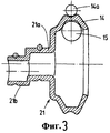
Фиг.3: продольное сечение втулки, служащей в качестве ведомого элемента первой ступени передачи и в качестве приводного механизма второй ступени передачи.Figure 3: a longitudinal section of a sleeve serving as a driven element of the first transmission stage and as a drive mechanism of the second transmission stage.
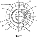
Фиг.4: поперечное сечение первой ступени передачи с пружиной сжатия в виде спирали в качестве прижимного элемента.Figure 4: cross section of the first gear stage with a compression spring in the form of a spiral as a clamping element.
Фиг.5: поперечное сечение первой ступени передачи с плоской пружиной в качестве прижимного элемента.Figure 5: cross section of the first gear stage with a flat spring as a clamping element.
Фиг.6: поперечное свечение первой ступени передачи с магнитами в качестве прижимных элементов.6: transverse glow of the first gear stage with magnets as clamping elements.
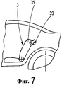
Фиг.7: схематичный вид сбоку сиденья автомобиля в заднем ряду.7: a schematic side view of a car seat in the back row.
Фиг.8: поперечное сечение первой ступени передачи с функцией демпфирования и опережения.Fig: cross-section of the first gear stage with the function of damping and advance.
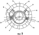
Фиг.9: поперечное сечение первой ступени передачи с функцией электрического соединения.Fig. 9: cross section of a first gear stage with electrical connection function.
Фиг.10: поперечное сечение первой ступени передачи с функцией механического соединения при помощи вилки переключения передач.Figure 10: cross section of the first gear stage with the function of mechanical connection using a gear shift fork.
Фиг.11: поперечное сечение первой ступени передачи с функцией механического соединения при помощи скользящего контакта.11: cross section of the first gear stage with the function of mechanical connection by means of a sliding contact.
Фиг.12: поперечное сечение первой ступени передачи с корпусом с различными жесткостями подшипников.12: cross section of the first gear stage with a housing with different bearing stiffnesses.
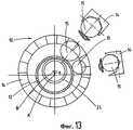
Фиг.13: поперечное сечение первой ступени передачи с разными передаточными отношениями, а также два продольных сечения в области обоих шариков.13: cross section of the first gear stage with different gear ratios, as well as two longitudinal sections in the region of both balls.
Фиг.14: поперечное сечение ступени передачи согласно уровню техники.14: cross section of a gear stage according to the prior art.
Сервопривод 1 для сиденья автомобиля 3 имеет корпус 5 и приводной двигатель 7, находящийся в корпусе 5. Корпус 5 выполнен, как правило, многосекционным, но имеет как можно меньше секций. Приводной двигатель 7, выполненный здесь как электродвигатель постоянного тока с внутренним скользящим контактом, имеет ротор 8, который установлен в корпусе 5 с возможностью вращения вокруг первой оси А и на котором находятся постоянные магниты, и электронно переключающийся статор 9. Ротор 8 установлен в корпусе 5 с помощью двух роторных подшипников 8а, выполненных как подшипники качения.The servo drive 1 for the seat of the
Сервопривод 1 имеет, кроме того, первую ступень передачи 10, включающую в себя приводной механизм 12, выполненный с возможностью вращения вокруг первой оси А, и ведомый элемент передачи 14, выполненный с возможностью вращения вокруг параллельной ей второй оси В, которые расположены в корпусе 5. Представленный кольцеобразный приводной механизм 12 выполнен предпочтительно за одно целое с ротором 8 приводного двигателя 7 и тем самым с помощью роторных подшипников 8а установлен в корпусе с возможностью качения.The servo drive 1 also has a
Однако возможно также раздельное выполнение ротора 8 и приводного механизма 12 с подходящим соединением и раздельное размещение в корпусе 5. Представленный также кольцеобразный ведомый элемент передачи 14 установлен в корпусе 5 с помощью подшипника со стороны привода 14а, также выполненного в виде подшипника качения. При этом первая ось А и вторая ось B разнесены между собой на эксцентриситет е, когда роторный подшипник 8а и подшипник со стороны привода 14а установлены неподвижно друг относительно друга. На изображении фиг.1 вторая ось В смещена вверх относительно первой оси А. Положение эксцентриситета е является, таким образом, в пространственном отношении неподвижным относительно корпуса 5. Относительно цилиндрической системы координат, определенной второй осью В, приводной механизм 12, имеющий меньший диаметр, находится радиально внутри, а ведомый элемент передачи 14, имеющий больший диаметр, находится радиально снаружи. Передача сил между приводным механизмом 12 и ведомым элементом 14 происходит в представленном примере выполнения в виде ступени фрикционной передачи с помощью, по меньшей мере, одного шарика 15 (или другого элемента качения), расположенного между приводным механизмом 12 и ведомым элементом 14, где между приводным механизмом 12 и ведомым элементом 14 образуется искривленное клиновидное свободное пространство, названное кратко клиновым зазором. При вращении приводного механизма 12 шарик 15 автоматически зажимается в направлении этого клинового зазора (на изображении фиг.1 в направлении вращения часовой стрелки), затем поворачивается вокруг собственной оси и приводит в действие ведомый элемент передачи 14 с пониженным числом оборотов. В данном случае для каждого направления приведения в действие шарик 15 (или другое тело качения) расположен точно между приводным механизмом 12 и ведомым элементом передачи 14, которые являются каждый раз (до направления вращения) равнодействующими.However, it is also possible to separately perform the
В отношении преобразования этой первой ступени передачи 10, когда вращаются все задействованные элементы конструкции исключительно вокруг своей собственной оси, существуют известные отношения, точнее, во-первых, отношение окружностей или радиусов приводного механизма 12 к ведомому элементу передачи 14 и, во-вторых, передаточное отношение самого шарика 15. С помощью контуров на приводном механизме 12 и/или ведомом элементе передачи 14 можно переместить места контактов с шариком 15 из той плоскости, которая расположена перпендикулярно осям А и В и на фиг.1 служит в качестве плоскости чертежа. В качестве проекции на эту плоскость получаются затем другие фактические радиусы шарика 15, т.е. радиус приводного механизма и радиус ведомого элемента передачи, благодаря чему передаточное отношение шарика 15 изменяется. Предпочтительно ведомый элемент передачи 14 на активной поверхности, указывающей в радиальном направлении внутрь, имеет контур, например желоб или V-образную канавку или т.п., внутри которой пробегает шарик 15, обкатывая при этом наклонные стенки. Таким образом, радиус приведения в действие шарика 15 уменьшается и становится даже меньше, чем радиус действия ведомого элемента передачи, и влияет на передаточное число. Например, выполнение V-образной канавки на приводном механизме и цилиндрической поверхности на ведомом элементе передачи может влиять на передаточное число повышающей передачи. Наряду с непосредственной передачей радиальных усилий это представляет собой преимущество ступени фрикционной передачи перед ступенью зубчатой передачи.With regard to the conversion of this first stage of
При вращательном моменте, рассматриваемом как постоянный, за счет эксцентриситета е получается угол между силовыми активными линиями действующих на шарик 15 сил и усилием в радиальном направлении, которое пропорционально тангенсу этого угла и значение которого и направление показаны на фиг.1 на внешней стороне ведомого элемента передачи. Величина этого радиального усилия допускает, если рассматривать все возможные положения шарика, двойное максимальное значение (теоретически бесконечно!) и минимальное значение. Если шарик 15 находится, например, на фиг.1 примерно в положении, соответствующем 12 или 6 часам, т.е. в запрещенной области угла R>, то угол при вершине клина минимальный, а наименьшие тангенциальные приводные усилия приводного механизма 14 приводят к чрезмерным усилиям в радиальном направлении, а при действительных элементах конструкции с ограниченными жесткостями, таким образом, - к радикальным деформациям. Делая вывод от противного, эта взаимозависимость для размещения в опорах приводного механизма 12 и ведомого элемента передачи 14 означает то, что для имеющихся подшипников с максимально допустимыми усилиями на опоре при данном максимальном вращающем моменте приводного механизма 12 шарик 15 может приводиться в действие только в точно определенной, разрешенной области угла R< (на изображении фиг.1 примерно между 13 ч и 16.30 ч). То же относится, конечно же, и к нагрузке самого шарика 15.With a rotational moment considered constant, due to the eccentricity e, an angle is obtained between the active lines of force acting on the
Описанные радиальные усилия, которые в один момент достигают минимума, должны приниматься в опорных узлах и в контакте с шариком и вызывают там неизбежно потери. Предпочтительная форма выполнения с максимальным коэффициентом полезного действия представляет вариант, при котором шарик занимает положение точно в области минимальных радиальных усилий, которая, помимо величины эксцентриситета е, также зависит от соотношений диаметров.The described radial forces, which at one moment reach a minimum, must be taken in the support nodes and in contact with the ball and there will inevitably cause losses. A preferred embodiment with a maximum efficiency is an option in which the ball is positioned precisely in the region of minimum radial forces, which, in addition to the eccentricity e, also depends on the ratio of the diameters.
В принципе описанную первую ступень передачи 10 с фиксированным эксцентриситетом можно применять в разных сочетаниях с другими ступенями передачи. В данном случае сервопривод 1 имеет вторую ступень передачи 20. Первая ступень передачи 10 служит в качестве предварительной ступени для второй ступени передачи 20, находящейся на стороне ведомого элемента передачи.In principle, the described
Вторая ступень передачи 20 выполнена в данном случае в виде зубчатой эксцентриковой планетарной передачи. Приводной вал 21, выполненный с возможностью вращения вокруг второй оси B, опирается с помощью первого эксцентричного участка 21а и второго эксцентричного участка 21b, смещенного вдоль второй оси В в осевом направлении, на две малые шестерни 22а и 22b, смещенные друг относительно друга предпочтительно на 180° и находящиеся в двух плоскостях. И первая малая шестерня 22а, и вторая малая шестерня 22b, которые выполнены предпочтительно одинаковыми, образуют снаружи зубчатое зацепление между собой и сцепляются с внутренним зацеплением корпуса 5, которое в отличие от малых шестерней 22а и 22b имеет большее число зубьев, по меньшей мере, на один больше. При вращении приводного вала 21, установленного по центру и жестко соединенного с ведомым элементом передачи 14, малые шестерни 22а и 22b выполняют движение обкатки корпуса 5. Малые шестерни 22а и 22b действуют при помощи штифтов и отверстий на общий выходной вал 24, который выполнен в виде полого вала и который также вращается. В данном случае приводной вал 21, а также выходной вал 23 расположены концентрично относительно второй оси В, так что в конечном счете приводной двигатель 7 расположен со смещением относительно двухступенчатой конструктивной группы передач, состоящей из первой ступени передачи 10 и второй ступени передачи 20, в общей сложности на эксцентриситет Е, который задан постоянным по положению и величине от общего корпуса 5. Действительно большое количество подшипников качения на фиг.2 служит повышению общего коэффициента полезного действия. Однако в измененных формах выполнения можно использовать также подшипники скольжения.The
В качестве конструктивного детального решения предпочтительно предусмотрено, что кольцеобразный ведомый элемент передачи 14 первой ступени передачи 10 и приводной вал 21 второй ступени передачи 20, соединенный с ним и выполненный в виде двойного эксцентрикового вала, выполнен как одно целое в виде втулки со всеми необходимыми канавками для шарика, и их можно изготовить предпочтительно в процессе деформации без снятия стружки или калибровки. На фиг.3 это видно.As a constructive detailed solution, it is preferably provided that the ring-shaped driven
За счет положения эксцентриситета е, в пространственном отношении неподвижного относительно корпуса 5 и тем самым также шариков 15, в условиях эксплуатации появляется множество новых возможностей для решения задач как в отношении конструктивного выполнения, так и в отношении общей функциональности. Далее будут описаны более подробно некоторые выгодные аспекты.Due to the position of the eccentricity e, which is spatially stationary relative to the
При известных выполнениях обкатных эксцентриков, движущихся по замкнутой траектории, шарики 15 совершают вращательное движение в пространстве, а прижимный элемент 31 должен вместе с ними принудительно совершать тоже вращательное движение для создания постоянно присутствующей, незначительной прижимной силы для шариков 15. Простым и часто применяемым решением являются при этом пружины сжатия в виде спиралей, как это показано на фиг.4. Однако такие спиральные пружины сжатия имеют тенденцию колебаться и вступают как с шариками 15, так и с ведомым элементом передачи 14 в контакт, который обязательно обладает потерями. На основании зафиксированного относительно корпуса 5 положения возможна реализация явно выгодного выполнения прижимного элемента 31, например применение жестко соединенной с корпусом плоской пружины из металла или пластмассы с минимальной плоскостью контактирования с шариком, как это представлено на фиг.5.With known designs of rolling eccentrics moving along a closed path, the
В качестве одной из форм выполнения, возможно, менее выгодной в экономическом плане, но более изящной с технической точки зрения и почти без потерь и шумов, предлагаются в качестве прижимных элементов 31 при применении стальных шариков 15 магниты для создания бесконтактной прижимной силы, как это видно на фиг.6.As one of the forms of execution, possibly less economically advantageous, but more elegant from a technical point of view and almost without loss and noise, magnets are used as clamping
Во всех случаях шарики 15 с помощью прижимного элемента или прижимных элементов 31 вдавливаются или затягиваются в клиновой зазор и тем самым прижимаются одновременно к приводному механизму 12 и ведомому элементу передачи 14. С конструктивной точки зрения, шарик 15 со своими силами, действующими под углом друг к другу, представляет собой в конечном итоге одновременно роликовый или в данном случае шариковый механизм свободного хода. Свободный ход представляет собой самовключающееся соединение. При эксплуатации, т.е. во время приводного движения, работает только тот шарик 15, который, благодаря приводному механизму 12, дальше продвигается в клиновой зазор и контактирует как с приводным механизмом 12, так и с ведомым элементом передачи 14. Находящийся напротив шарик 15, выполненный для противоположного направления движения привода, несмотря на прижимной элемент 31, выскакивает из предназначенного для него клинового зазора и освобождается от двойного контакта.In all cases, the
Действие в виде роликового или шарикового механизма свободного хода можно вполне использовать в некоторых случаях в технике приведения в действие в рациональных комбинациях. На фиг.7 показана область задней части салона автомобиля с электрически деблокированным замком 33 на верхнем краю спинки 35 сиденья автомобиля 3. Для комфортного и быстрого изменения салона автомобиля известны такие конструкции, при которых спинка 35 с нагрузкой на пружину установлена в положение вперед и зафиксирована с возможностью освобождения. Таким образом, спинка 35 при отпирании с помощью электрики замка 33 самостоятельно наклоняется вперед. Для возврата в представленное положение спинку 35 нужно снова наклонить вручную.The action in the form of a roller or ball freewheel mechanism can be quite used in some cases in the actuation technique in rational combinations. 7 shows the area of the rear of the passenger compartment with an electrically
Другое повышение комфортабельности достигается, во-первых, за счет, при необходимости, контролируемого гашения колебаний вследствие наклонения вперед, вызванного действием пружины, и, во-вторых, за счет повторного откидывания с помощью электрики. Этого можно добиться с помощью варианта сервопривода 1, имеющего заявленное выполнение первой ступени передачи 10 с фиксированным положением эксцентриситета, и с помощью выполнения фрикционного диска, если подключенные ступени передачи не являются самотормозящими, что в описанном применении абсолютно рационально.Another increase in comfort is achieved, firstly, due to, if necessary, controlled damping of vibrations due to forward bending caused by the action of the spring, and, secondly, due to repeated folding using electrics. This can be achieved with the option of a servo drive 1 having the claimed execution of the
На фиг.8 показан вариант передачи, которая работает в этом случае с предварительно намагниченным шариком 15. Сервопривод 1 с этой первой ступенью передачи 10 встроен в узел крепления, служащий в качестве регулятора наклона спинки. Если в положении, показанном на фиг.7, спинка 35 в области своего верхнего края при воздействии электрического тока деблокируется и отклоняется вперед, т.е. против часовой стрелки, как это показано на фиг.7, ведомый элемент передачи 14 вращается на фиг.8 также против часовой стрелки, удерживает контакт с приводным механизмом 12 и приводит в действие ротор 8. В предложенном случае с электродвигателем постоянного тока ротор 8 может нести нагрузку либо без точно контролируемого тормозного момента, либо с ним, например, для определения максимальной скорости отклонения и замедления движения незадолго до завершения возможного угла движения. Если спинку 35 нужно затем снова откинуть с помощью электрического тока, ротор 8 в данном случае работает против движения часовой стрелки, а ведомый элемент передачи 14, а также спинка 35 вращаются по часовой стрелке на фиг.7 и 8. Существует также особенность, заключающаяся в том, что это движение спинки 35, созданное двигателем, можно опередить вручную («функция опережения»). В случае если на ведомом элементе передачи инициируется момент, т.е. привнесенное снаружи ускорение ведомого элемента передачи 14, то шариковый механизм свободного хода открывается автоматически, т.е. шарик 15 выходит из клинового зазора, приводной механизм работает вхолостую, и спинку 35 можно отклонить вручную. При прерывании подачи электропитания или в аварийных ситуациях это позволит откинуть спинку 35 только вручную.On Fig shows a transmission option, which works in this case with a
На базе физических соотношений шарика 15, которые в описанном как раз случае способствуют автоматическому расцеплению первой ступени передачи 10, эта первая ступень передачи 10 простым образом выполняет другую функцию, необходимую в технике приводных механизмов, а именно работу включенного сцепления, которая в случае необходимости может даже зависеть от направления. На фиг.9 показано расположение, при котором оба шарика 15 независимо друг от друга могут занимать пассивную или активную позицию. Для обоих шариков 15 в верхней области свободного пространства между приводным механизмом 12 и ведомым элементом передачи 14 предусмотрено устройство для удержания 37 (здесь представлена простая геометрия с очень слабым магнитом). Устройство для удержания 37 устанавливает шарик 15 в положение покоя, так что он не контактирует с приводным механизмом 12 и/или ведомым элементом передачи 14 (т.е., по меньшей мере, с одним или, при необходимости, с двумя конструктивными элементами), благодаря чему в положении покоя приводной механизм 12 и ведомый элемент передачи 14 полностью разъединены между собой. В нижней области свободного пространства предусмотрены два отдельных или отдельно включаемых электромагнитов, которые служат в качестве прижимных элементов 31 и которые при активизации притягивают шарик 15 и тем самым запирают замкнутый силовой поток для этого соответствующего направления движения. Так как прижимные силы, необходимые при повышенных вращательных моментах, при эксплуатации настраиваются автоматически вследствие действия клина, то для включения такого сцепления достаточно минимума энергии, которая должна обеспечить только слабый контакт к началу движения. Электромагниты, используемые как прижимные элементы 31, могут затем при работе снова включаться в отсутствие электропитания.Based on the physical relations of the
Наряду с уже описанной реализацией соединительной функции с помощью электропитания возможна реализация решения механическим путем. В примере выполнения согласно фиг.10 применяют, например, поводковые вилки 41, из которых представлена только одна. Такой поводковой вилкой 41 можно управлять извне. Управляемые поводковые вилки 41 приводят шарики 15 соответственно в активную позицию (внутрь клинового зазора) или пассивную позицию (вне клинового зазора) и тем самым позволяют приводному двигателю 7 выключиться, чтобы, например, выполнить ручную быструю регулировку или снова аварийное управление, как это было описано в связи с фиг.7 и 8.Along with the already described implementation of the connecting function by means of power supply, it is possible to implement the solution mechanically. In the exemplary embodiment of FIG. 10, for example, driving
Еще одно выгодное выполнение соединительной функции представлено на фиг.11, на которой можно видеть направляющее кольцо для шарика 43, которое охватывает приводной механизм 12 и находится с ним в трех местах в легком скользящем контакте и направляет шарик 15. Направляющее кольцо для шарика 43, при условии слабого скользящего контакта с приводным механизмом 12, имеет тенденцию сдвигать шарик 15 внутрь свободного пространства всегда в направлении привода ротора 8 (т.е. внутрь клинового зазора) и далее в разъединенном состоянии само, как и шарик 15, сохраняет свое угловое положение. При изменении направления вращения, напротив, шарик 15, освобожденный от своего контакта, отклоняется в противоположную сторону. При этом получающаяся экономия от отсутствия второго шарика 15 имеет меньше значения, чем тот факт, что с помощью этого устройства без других активных элементов управления или магнитов передачу можно полностью выключить, обратно вращая ротор 8 (и вместе с тем приводной механизм 12) после завершения приводного движения под известным углом (на фиг.11 примерно 80° против часовой стрелки). Это дает возможность контролировать разгрузку напряжений во всем сервоприводе 1 и позволяет, например, охватить опорные узлы приводного механизма и ведомого элемента передачи эластомерным кольцом с целью уменьшения звукопроведения или также для целенаправленного управления упругим смещением элементов передачи при работе под нагрузкой. В качестве побочного эффекта следует отметить, что такое выполнение позволяет также использовать немагнитные материалы для шарика, например керамику или пластмассу.Another advantageous connection function is shown in FIG. 11, in which a guide ring for the
Возможное выполнение, предусматривающее корпус 5 умышленно с разными жесткостями подшипников, представлено на фиг.12. С помощью таких разных и зависящих от пространственной ориентации жесткостей подшипников можно, например, уменьшить радиальные усилия. В данном случае речь идет о варианте выполнения фиг.11. В частности, при использовании термопластичных пластмасс в качестве материала для корпуса рекомендуется выключение первой ступени передачи 10 для сведения к минимуму расползания материала после более длительного простоя при высоких температурах.A possible implementation, providing the
С помощью описанных возможностей подключения и освобождения шариков 15 напрашивается вывод, что первую ступень передачи 10 можно представить в виде передачи с разными, зависящими от направления или включаемыми передаточными, отношениями. На фиг.13 в качестве примера представлен ступенчатый внутренний контур ведомого элемента передачи 14. В сочетании с разным из-за эксцентриситета е удалением от приводного механизма 12 шарики 15 по-разному контактируют с этим внутренним контуром. Тем самым эти ступени передачи могут переключаться благодаря освобождению одного шарика 15 и подключению другого шарика 15. В области привода сиденья зачастую имеют место зависящие от направления движения затраты мощности или моментов. С такой возможностью переключения для ситуаций с разными нагрузками (регулятор высоты сидения вверх - большой момент, регулятор высоты вниз - малый момент) априори можно установить подходящее передаточное число для каждого направления движения. По тому же принципу можно установить более двух передаточных отношений.Using the described possibilities of connecting and releasing the
В качестве альтернативы для показанного варианта выполнения фиг.13 с двумя шариками 15 разного передаточного отношения в одном единственном ведомом элементе передачи 14 можно, разумеется, в том же смысле определить также геометрию контакта приводного механизма 12 или можно расположить один или несколько ведомых элементов передачи 14 (или приводных механизмов 12) аксиально друг над другом или предусмотреть два разных контура на ведомом элементе передачи 14 (или на приводном механизме 12). Вместо шариков 15 можно предусмотреть и другие тела качения.As an alternative to the illustrated embodiment of FIG. 13 with two
Перечень обозначенийNotation list
1 сервопривод1 servo
3 сиденье автомобиля3 car seat
5 корпус5 building
7 приводной двигатель7 drive motor
8 ротор8 rotor
8а подшипник ротора8a rotor bearing
9 статор9 stator
10 первая ступень передачи10 first gear
12 приводной механизм12 drive mechanism
14 ведомый элемент передачи14 transmission slave
14а подшипник ведомого элемента передачи14a transmission driven element bearing
15 шарик15 ball
20 вторая ступень передачи20 second gear
21 приводной вал21 drive shaft
21а первый эксцентриковый участок21a first eccentric section
21b второй эксцентриковый участок21b second eccentric section
22а первая малая шестерня22a first small gear
22b вторая малая шестерня22b second small gear
24 ведомый вал24 driven shaft
31 прижимной элемент31 clamping element
33 замок спинки33 backrest lock
35 спинка35 back
37 устройство для удержания37 holding device
41 поводковая вилка41 leash fork
43 направляющее кольцо для шарика43 ball guide ring
А первая осьAnd the first axis
В вторая осьIn the second axis
е эксцентриситетeccentricity
R< разрешенная область углаR <allowed angle range
R> запрещенная область углаR> band gap
Claims (11)
Applications Claiming Priority (3)
| Application Number | Priority Date | Filing Date | Title |
|---|---|---|---|
| DE102007051031 | 2007-10-23 | ||
| DE102007051031.6 | 2007-10-23 | ||
| PCT/DE2007/002118 WO2009052771A1 (en) | 2007-10-23 | 2007-11-16 | Gear stage |
Publications (2)
| Publication Number | Publication Date |
|---|---|
| RU2010119572A RU2010119572A (en) | 2011-11-27 |
| RU2476740C2 true RU2476740C2 (en) | 2013-02-27 |
Family
ID=39327413
Family Applications (2)
| Application Number | Title | Priority Date | Filing Date |
|---|---|---|---|
| RU2010119572/11A RU2476740C2 (en) | 2007-10-23 | 2007-11-16 | Transmission stage |
| RU2010119571/11A RU2499695C2 (en) | 2007-10-23 | 2008-10-17 | Gearing stage |
Family Applications After (1)
| Application Number | Title | Priority Date | Filing Date |
|---|---|---|---|
| RU2010119571/11A RU2499695C2 (en) | 2007-10-23 | 2008-10-17 | Gearing stage |
Country Status (9)
| Country | Link |
|---|---|
| US (2) | US8435150B2 (en) |
| EP (2) | EP2200862B1 (en) |
| JP (2) | JP5319687B2 (en) |
| KR (2) | KR101394918B1 (en) |
| CN (2) | CN101835656B (en) |
| DE (4) | DE112007003746A5 (en) |
| PL (1) | PL2200864T3 (en) |
| RU (2) | RU2476740C2 (en) |
| WO (3) | WO2009052771A1 (en) |
Families Citing this family (15)
| Publication number | Priority date | Publication date | Assignee | Title |
|---|---|---|---|---|
| DE112007003746A5 (en) * | 2007-10-23 | 2010-09-23 | Keiper Gmbh & Co. Kg | gear stage |
| DE102009014376B3 (en) * | 2009-03-19 | 2010-07-22 | Keiper Gmbh & Co. Kg | Drive device for a vehicle seat, in particular for a motor vehicle seat |
| JP5743770B2 (en) * | 2011-07-20 | 2015-07-01 | 住友重機械工業株式会社 | Speed reducer incorporation method and eccentric oscillation type speed reducer |
| FR2994134B1 (en) * | 2012-08-03 | 2014-08-08 | Faurecia Sieges Automobile | VEHICLE SEAT COMPRISING A MOTORIZED ADJUSTABLE PART, ELECTRICAL CONTROL UNIT FOR A MOTOR VEHICLE |
| JP6067293B2 (en) * | 2012-09-19 | 2017-01-25 | デルタ工業株式会社 | Angle adjustment device for seat bracket |
| WO2014077389A1 (en) * | 2012-11-19 | 2014-05-22 | テイ・エス テック株式会社 | Operating lever, seat device, and operating section structure |
| WO2015161430A1 (en) * | 2014-04-22 | 2015-10-29 | 上海锘威传动控制有限责任公司 | Magneto-rheological servo speed regulating and reducing device and assembly and control method therefor |
| DE102014209465A1 (en) * | 2014-05-19 | 2015-11-19 | Hamm Ag | Seat for a driver of a construction machine, construction machine, and method for adjusting a seat |
| DE102014222592A1 (en) * | 2014-09-08 | 2016-03-10 | Sms Group Gmbh | Drive a machine, torque motor, clutch device, device for processing materials and use of a torque motor |
| US9796301B2 (en) * | 2015-09-22 | 2017-10-24 | Ford Global Technologies, Llc | Ball bearing application for seat recliner disk mechanisms |
| JP2017116070A (en) * | 2015-12-25 | 2017-06-29 | アイシン精機株式会社 | Motion conversion device for vehicle |
| FR3071784B1 (en) * | 2017-09-29 | 2019-10-18 | Faurecia Sieges D'automobile | SCREW ADJUSTMENT MECHANISM, SLIDE COMPRISING SUCH AN ADJUSTING MECHANISM AND SEAT COMPRISING SUCH A SLIDER. |
| CN111226059B (en) * | 2017-12-20 | 2022-11-18 | Abb瑞士股份有限公司 | Friction cycloid driver |
| CN113692507A (en) * | 2019-04-01 | 2021-11-23 | 约翰·帕洛斯基 | Gearless transmission unit with one-sided positioning finger-shaped auxiliary element |
| CN113335149A (en) * | 2021-07-02 | 2021-09-03 | 湖南普奇新能源研究院有限公司 | More comfortable sightseeing electric vehicle |
Citations (5)
| Publication number | Priority date | Publication date | Assignee | Title |
|---|---|---|---|---|
| CH229919A (en) * | 1941-10-13 | 1943-11-30 | Saechsische Armaturen Fabrik W | Friction gear. |
| SU537619A3 (en) * | 1972-06-07 | 1976-11-30 | Фриц Кейпер (Фирма) | Hinge for adjustable vehicle seat |
| SU655846A1 (en) * | 1975-07-09 | 1979-04-05 | Предприятие П/Я А-1772 | Friction gearing |
| EP1323909A2 (en) * | 2001-12-27 | 2003-07-02 | Hks Co., Ltd. | Supercharger |
| DE102005039733A1 (en) * | 2005-08-23 | 2007-03-01 | Keiper Gmbh & Co.Kg | Gearing stage for servo drive of vehicle seat, has drive to support another drive under parallel misalignment of axes by body and drive latter drive during rotation of eccentrics, where driven driver executes movement by tire and guide |
Family Cites Families (30)
| Publication number | Priority date | Publication date | Assignee | Title |
|---|---|---|---|---|
| US247669A (en) * | 1881-09-27 | Screw-driver | ||
| DE109463C (en) | 1900-01-01 | |||
| GB109463A (en) | ||||
| US1194288A (en) * | 1916-08-08 | Mechanical movement | ||
| US605845A (en) * | 1898-06-21 | Change speed mechanism | ||
| FR554065A (en) * | 1921-07-29 | 1923-06-05 | Sulzer Ag | Friction mechanism |
| FR601616A (en) * | 1924-11-04 | 1926-03-05 | Roller or ball speed reducer or multiplier system | |
| US2514569A (en) * | 1944-09-01 | 1950-07-11 | Enquist Gosta Thure Harry | Releasable coupling device |
| US4481842A (en) * | 1981-08-31 | 1984-11-13 | Wedgtrac Corporation | Torque limit drive transmission |
| US4555963A (en) * | 1983-11-17 | 1985-12-03 | Wedgtrac Corporation | Torque limit drive transmission |
| FR2656392B2 (en) * | 1989-06-30 | 1994-05-06 | Cousin Freres Sa | GAME RETRAPING DEVICE FOR SAID CONTINUOUS ARTICULATIONS WITH EPICYCLOUIDAL TRAIN. |
| DE4310158C1 (en) * | 1993-03-29 | 1994-12-22 | Braren Cyclo Getriebe | Orbital gearbox with two output shafts |
| RU2124661C1 (en) * | 1996-11-04 | 1999-01-10 | Акционерное общество "АвтоВАЗ" | Planetary gear (design versions) |
| US5931759A (en) | 1997-05-09 | 1999-08-03 | Nsk Ltd. | Friction-roller speed changer |
| JP2000016314A (en) | 1998-07-02 | 2000-01-18 | Nippon Seiko Kk | Electrically-driven power steering device |
| JP2000291754A (en) * | 1999-04-07 | 2000-10-20 | Nsk Ltd | Friction roller-type transmission |
| JP2002106662A (en) | 2000-10-05 | 2002-04-10 | Nsk Ltd | Frictional roller type transmission |
| DE10228103A1 (en) | 2002-06-24 | 2004-01-15 | Bayer Cropscience Ag | Fungicidal active ingredient combinations |
| DE10232247B3 (en) * | 2002-07-17 | 2004-03-04 | Bühler Motor GmbH | Eccentric gear used as a rolling eccentric gear comprises a sun wheel, a planet wheel rolling on the inner side of an external geared wheel, and an internal geared wheel |
| JP2004190787A (en) | 2002-12-11 | 2004-07-08 | Nsk Ltd | Motor with friction roller type transmission |
| JP2006509984A (en) * | 2002-12-13 | 2006-03-23 | ザ ティムケン カンパニー | Integrated device of electric motor and traction drive |
| JP2004316881A (en) | 2003-04-18 | 2004-11-11 | Hideo Ogoshi | Transmission roller supporting mechanism for wedge roller transmission device |
| US7318508B2 (en) * | 2004-02-23 | 2008-01-15 | Pentax Corporation | One-way rotational transfer mechanism |
| DE102004019466B4 (en) | 2004-04-15 | 2006-07-13 | Keiper Gmbh & Co.Kg | Adjustment device for a vehicle seat |
| DE102004049994B3 (en) * | 2004-10-14 | 2006-03-16 | Keiper Gmbh & Co.Kg | Gear stage for a vehicle seat |
| EP1895898B1 (en) | 2005-06-29 | 2011-02-16 | Compumedics Limited | Sensor assembly with conductive bridge |
| DE102006005906A1 (en) * | 2005-08-23 | 2007-08-30 | Keiper Gmbh & Co.Kg | gear stage |
| US7614974B2 (en) * | 2007-03-28 | 2009-11-10 | Thyssenkrupp Presta Ag | Transmission for vehicle steering apparatus |
| DE112007003746A5 (en) * | 2007-10-23 | 2010-09-23 | Keiper Gmbh & Co. Kg | gear stage |
| JP2009207702A (en) * | 2008-03-05 | 2009-09-17 | Fuji Kiko Co Ltd | Automotive seat reclining device |
-
2007
- 2007-11-16 DE DE112007003746T patent/DE112007003746A5/en not_active Withdrawn
- 2007-11-16 CN CN2007801012201A patent/CN101835656B/en not_active Expired - Fee Related
- 2007-11-16 EP EP07866206.1A patent/EP2200862B1/en not_active Not-in-force
- 2007-11-16 DE DE102007056392A patent/DE102007056392A1/en not_active Withdrawn
- 2007-11-16 RU RU2010119572/11A patent/RU2476740C2/en not_active IP Right Cessation
- 2007-11-16 DE DE102007056390A patent/DE102007056390B4/en not_active Expired - Fee Related
- 2007-11-16 WO PCT/DE2007/002118 patent/WO2009052771A1/en active Application Filing
- 2007-11-16 KR KR1020107011276A patent/KR101394918B1/en not_active IP Right Cessation
- 2007-11-16 DE DE102007056391A patent/DE102007056391B4/en not_active Expired - Fee Related
- 2007-11-16 US US12/739,252 patent/US8435150B2/en active Active
- 2007-11-16 JP JP2010530266A patent/JP5319687B2/en not_active Expired - Fee Related
-
2008
- 2008-10-17 CN CN200880112849.0A patent/CN101835657B/en not_active Expired - Fee Related
- 2008-10-17 RU RU2010119571/11A patent/RU2499695C2/en not_active IP Right Cessation
- 2008-10-17 US US12/739,269 patent/US20110037306A1/en not_active Abandoned
- 2008-10-17 WO PCT/DE2008/001766 patent/WO2009052813A1/en active Application Filing
- 2008-10-17 EP EP08842208.4A patent/EP2200864B1/en not_active Not-in-force
- 2008-10-17 WO PCT/DE2008/001765 patent/WO2009052812A1/en active Application Filing
- 2008-10-17 PL PL08842208T patent/PL2200864T3/en unknown
- 2008-10-17 JP JP2010530273A patent/JP5485158B2/en not_active Expired - Fee Related
- 2008-10-17 KR KR1020107011277A patent/KR101391309B1/en not_active IP Right Cessation
Patent Citations (5)
| Publication number | Priority date | Publication date | Assignee | Title |
|---|---|---|---|---|
| CH229919A (en) * | 1941-10-13 | 1943-11-30 | Saechsische Armaturen Fabrik W | Friction gear. |
| SU537619A3 (en) * | 1972-06-07 | 1976-11-30 | Фриц Кейпер (Фирма) | Hinge for adjustable vehicle seat |
| SU655846A1 (en) * | 1975-07-09 | 1979-04-05 | Предприятие П/Я А-1772 | Friction gearing |
| EP1323909A2 (en) * | 2001-12-27 | 2003-07-02 | Hks Co., Ltd. | Supercharger |
| DE102005039733A1 (en) * | 2005-08-23 | 2007-03-01 | Keiper Gmbh & Co.Kg | Gearing stage for servo drive of vehicle seat, has drive to support another drive under parallel misalignment of axes by body and drive latter drive during rotation of eccentrics, where driven driver executes movement by tire and guide |
Also Published As
Similar Documents
| Publication | Publication Date | Title |
|---|---|---|
| RU2476740C2 (en) | Transmission stage | |
| JP2011500231A5 (en) | ||
| US5780957A (en) | Moving linear piezoelectric motor for vehicle applications | |
| JP5002011B2 (en) | Electromechanically switchable shape-coupled freewheel, electromechanical brake for an automobile with such a freewheel, and method for adjusting the air gap of such a brake | |
| KR101312616B1 (en) | Eccentricity gear step | |
| JP5549877B2 (en) | Load-sensitive transmission | |
| US6561943B1 (en) | Clutch apparatus for automatic transmission | |
| WO2008082991A1 (en) | Three shaft friction drive | |
| CN111971494B (en) | Shift actuator | |
| JP2002155970A (en) | Clutch structure | |
| KR20090040075A (en) | Clutch actuator for dual clutch transmission | |
| CN112412198A (en) | Passive whole-course locking device based on direction control | |
| CN106763298B (en) | centrifugal clutch | |
| US20230341004A1 (en) | Clutch device | |
| JP2019217880A (en) | Coupling device | |
| JP2005069253A (en) | Pulley width adjusting device for continuously variable transmission | |
| JP2003209952A (en) | Linear actuator fitted with clutch mechanism | |
| KR102554877B1 (en) | Transmission for electric vehicle | |
| CN111140607A (en) | Bearing clutch | |
| JP2023157455A (en) | drive mechanism | |
| JP4294701B2 (en) | Linear actuator | |
| JP2024001370A (en) | rotary actuator | |
| KR20240020972A (en) | Recliner for vehicle seat | |
| CN118532412A (en) | Wire control mechanical brake | |
| CN114321208A (en) | Bidirectional controllable clutch, power assembly and automobile |
Legal Events
| Date | Code | Title | Description |
|---|---|---|---|
| MM4A | The patent is invalid due to non-payment of fees |
Effective date: 20171117 |