RU2456503C2 - Light beam former - Google Patents
Light beam former Download PDFInfo
- Publication number
- RU2456503C2 RU2456503C2 RU2009140774/28A RU2009140774A RU2456503C2 RU 2456503 C2 RU2456503 C2 RU 2456503C2 RU 2009140774/28 A RU2009140774/28 A RU 2009140774/28A RU 2009140774 A RU2009140774 A RU 2009140774A RU 2456503 C2 RU2456503 C2 RU 2456503C2
- Authority
- RU
- Russia
- Prior art keywords
- optical device
- diopter
- light
- axis
- collecting
- Prior art date
Links
- 230000003287 optical effect Effects 0.000 claims description 49
- 238000011144 upstream manufacturing Methods 0.000 claims description 3
- 230000017525 heat dissipation Effects 0.000 claims 1
- 230000000694 effects Effects 0.000 abstract description 3
- 238000005286 illumination Methods 0.000 abstract description 2
- 239000000126 substance Substances 0.000 abstract 1
- 230000002093 peripheral effect Effects 0.000 description 6
- 238000011161 development Methods 0.000 description 4
- 230000018109 developmental process Effects 0.000 description 4
- 238000012423 maintenance Methods 0.000 description 4
- 238000004519 manufacturing process Methods 0.000 description 4
- 239000000463 material Substances 0.000 description 3
- 239000004033 plastic Substances 0.000 description 3
- 229920003023 plastic Polymers 0.000 description 3
- 229920000193 polymethacrylate Polymers 0.000 description 3
- 239000003086 colorant Substances 0.000 description 2
- 239000011521 glass Substances 0.000 description 2
- 238000001746 injection moulding Methods 0.000 description 2
- 239000000243 solution Substances 0.000 description 2
- 201000004569 Blindness Diseases 0.000 description 1
- DGAQECJNVWCQMB-PUAWFVPOSA-M Ilexoside XXIX Chemical compound C[C@@H]1CC[C@@]2(CC[C@@]3(C(=CC[C@H]4[C@]3(CC[C@@H]5[C@@]4(CC[C@@H](C5(C)C)OS(=O)(=O)[O-])C)C)[C@@H]2[C@]1(C)O)C)C(=O)O[C@H]6[C@@H]([C@H]([C@@H]([C@H](O6)CO)O)O)O.[Na+] DGAQECJNVWCQMB-PUAWFVPOSA-M 0.000 description 1
- 238000004364 calculation method Methods 0.000 description 1
- 230000021615 conjugation Effects 0.000 description 1
- 230000004907 flux Effects 0.000 description 1
- 238000009434 installation Methods 0.000 description 1
- 239000002932 luster Substances 0.000 description 1
- 238000007620 mathematical function Methods 0.000 description 1
- 238000011430 maximum method Methods 0.000 description 1
- 238000000034 method Methods 0.000 description 1
- 229920003229 poly(methyl methacrylate) Polymers 0.000 description 1
- 239000004417 polycarbonate Substances 0.000 description 1
- 229920000515 polycarbonate Polymers 0.000 description 1
- 239000004926 polymethyl methacrylate Substances 0.000 description 1
- 230000035945 sensitivity Effects 0.000 description 1
- 238000007493 shaping process Methods 0.000 description 1
- 229910052708 sodium Inorganic materials 0.000 description 1
- 239000011734 sodium Substances 0.000 description 1
- 239000012780 transparent material Substances 0.000 description 1
Images
Classifications
-
- F—MECHANICAL ENGINEERING; LIGHTING; HEATING; WEAPONS; BLASTING
- F21—LIGHTING
- F21V—FUNCTIONAL FEATURES OR DETAILS OF LIGHTING DEVICES OR SYSTEMS THEREOF; STRUCTURAL COMBINATIONS OF LIGHTING DEVICES WITH OTHER ARTICLES, NOT OTHERWISE PROVIDED FOR
- F21V5/00—Refractors for light sources
- F21V5/04—Refractors for light sources of lens shape
-
- G—PHYSICS
- G02—OPTICS
- G02B—OPTICAL ELEMENTS, SYSTEMS OR APPARATUS
- G02B19/00—Condensers, e.g. light collectors or similar non-imaging optics
- G02B19/0004—Condensers, e.g. light collectors or similar non-imaging optics characterised by the optical means employed
- G02B19/0009—Condensers, e.g. light collectors or similar non-imaging optics characterised by the optical means employed having refractive surfaces only
- G02B19/0014—Condensers, e.g. light collectors or similar non-imaging optics characterised by the optical means employed having refractive surfaces only at least one surface having optical power
-
- G—PHYSICS
- G02—OPTICS
- G02B—OPTICAL ELEMENTS, SYSTEMS OR APPARATUS
- G02B19/00—Condensers, e.g. light collectors or similar non-imaging optics
- G02B19/0033—Condensers, e.g. light collectors or similar non-imaging optics characterised by the use
- G02B19/0047—Condensers, e.g. light collectors or similar non-imaging optics characterised by the use for use with a light source
- G02B19/0061—Condensers, e.g. light collectors or similar non-imaging optics characterised by the use for use with a light source the light source comprising a LED
-
- G—PHYSICS
- G02—OPTICS
- G02B—OPTICAL ELEMENTS, SYSTEMS OR APPARATUS
- G02B27/00—Optical systems or apparatus not provided for by any of the groups G02B1/00 - G02B26/00, G02B30/00
- G02B27/09—Beam shaping, e.g. changing the cross-sectional area, not otherwise provided for
- G02B27/0938—Using specific optical elements
- G02B27/095—Refractive optical elements
- G02B27/0955—Lenses
-
- F—MECHANICAL ENGINEERING; LIGHTING; HEATING; WEAPONS; BLASTING
- F21—LIGHTING
- F21S—NON-PORTABLE LIGHTING DEVICES; SYSTEMS THEREOF; VEHICLE LIGHTING DEVICES SPECIALLY ADAPTED FOR VEHICLE EXTERIORS
- F21S2/00—Systems of lighting devices, not provided for in main groups F21S4/00 - F21S10/00 or F21S19/00, e.g. of modular construction
-
- F—MECHANICAL ENGINEERING; LIGHTING; HEATING; WEAPONS; BLASTING
- F21—LIGHTING
- F21S—NON-PORTABLE LIGHTING DEVICES; SYSTEMS THEREOF; VEHICLE LIGHTING DEVICES SPECIALLY ADAPTED FOR VEHICLE EXTERIORS
- F21S8/00—Lighting devices intended for fixed installation
- F21S8/08—Lighting devices intended for fixed installation with a standard
-
- F—MECHANICAL ENGINEERING; LIGHTING; HEATING; WEAPONS; BLASTING
- F21—LIGHTING
- F21W—INDEXING SCHEME ASSOCIATED WITH SUBCLASSES F21K, F21L, F21S and F21V, RELATING TO USES OR APPLICATIONS OF LIGHTING DEVICES OR SYSTEMS
- F21W2131/00—Use or application of lighting devices or systems not provided for in codes F21W2102/00-F21W2121/00
- F21W2131/10—Outdoor lighting
- F21W2131/103—Outdoor lighting of streets or roads
-
- F—MECHANICAL ENGINEERING; LIGHTING; HEATING; WEAPONS; BLASTING
- F21—LIGHTING
- F21Y—INDEXING SCHEME ASSOCIATED WITH SUBCLASSES F21K, F21L, F21S and F21V, RELATING TO THE FORM OR THE KIND OF THE LIGHT SOURCES OR OF THE COLOUR OF THE LIGHT EMITTED
- F21Y2115/00—Light-generating elements of semiconductor light sources
- F21Y2115/10—Light-emitting diodes [LED]
Landscapes
- Physics & Mathematics (AREA)
- General Physics & Mathematics (AREA)
- Optics & Photonics (AREA)
- Engineering & Computer Science (AREA)
- General Engineering & Computer Science (AREA)
- Non-Portable Lighting Devices Or Systems Thereof (AREA)
- Lenses (AREA)
- Analysing Materials By The Use Of Radiation (AREA)
Abstract
Description
Область техники, к которой относится изобретениеFIELD OF THE INVENTION
Изобретение относится к оптическому устройству для придания световому лучу требуемой формы, причем это устройство также называется “формирователем светового луча”. Это оптическое устройство особенно важно для освещаемых поверхностей, которые имеют большую длину по сравнению с их шириной, таких как дорога, улица или автомагистраль.The invention relates to an optical device for shaping a light beam, which device is also called a “light beam shaper”. This optical device is especially important for illuminated surfaces that are longer than their width, such as a road, street or highway.
Предпосылки создания изобретенияBACKGROUND OF THE INVENTION
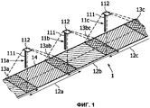
На фиг.1 изображен схематичный перспективный вид секции 1 дороги, оснащенной тремя уличными светильниками 11a, 11b, 11c. Уличные светильники, или канделябры, содержат столб 111 светильника и головку 112 светильника. Каждый уличный светильник освещает соответствующую уличную зону 12a, 12b, 12c секции 1 дороги, причем каждая уличная зона имеет длину L. Эти освещенные уличные зоны могут слегка перекрываться в зонах 13a, 13ab, 13bc, 13c перекрытия. Обычно, как изображено на фиг.1, уличные светильники отстоят от границы 14 секции 1 дороги. Например, они возводятся на тротуаре, на границе 14 секции 1 дороги. Действительно, из-за потока транспорта невозможно установить уличные светильники прямо над зонами, которые должны быть освещены, так как это было бы очень опасно.Figure 1 shows a schematic perspective view of a
Известно использование отражателей, расположенных в головке светильника, поперек пути света, для направления светового луча под соответствующим углом в направлении улицы.It is known to use reflectors located in the head of the lamp across the path of light to direct the light beam at an appropriate angle in the direction of the street.
Более того, предпочтительно увеличить расстояние между двумя последовательными уличными светильниками 11a и 11b, или 11b и 11c для уменьшения стоимости установки и обслуживания. Различные системы отражателей были предложены для получения вытянутого луча. Такие системы отражателей являются довольно крупногабаритными.Moreover, it is preferable to increase the distance between two
Обычными источниками света для уличного освещения являются разрядные лампы высокой интенсивности, такие как натриевые паросветные лампы, флуоресцентные шары или флуоресцентные трубки. Однако эти типы источников являются довольно крупногабаритными и они требуют частого и длительного обслуживания. Последствием громоздкости является то, что головки светильника также являются крупногабаритными, что может быть недостатком в условиях ветра.Common light sources for street lighting are high-intensity discharge lamps, such as sodium vapor lamps, fluorescent balls, or fluorescent tubes. However, these types of sources are quite large and they require frequent and lengthy maintenance. A consequence of cumbersome is that the lamp heads are also large, which may be a disadvantage in wind conditions.
Краткое изложение сущности изобретенияSummary of the invention
Целью вариантов осуществления изобретения является разработка уличного светильника, который позволяет равномерно освещать уличную зону в продольном направлении без риска ослепления пользователя улицы.The aim of the embodiments of the invention is to develop a street lamp that allows you to evenly illuminate the street zone in the longitudinal direction without the risk of blindness to the street user.
Другой целью вариантов осуществления изобретения является разработка уличного светильника, который удовлетворяет правилам уличного освещения, в особенности, относительно однородности освещения, интенсивности освещения, блескости и загрязнения неба.Another objective of the embodiments of the invention is the development of a street lamp that meets the rules of street lighting, in particular with respect to uniformity of lighting, light intensity, luster and sky pollution.
Другой целью вариантов осуществления изобретения является разработка уличного светильника с уменьшенной чувствительностью к ветру.Another objective of embodiments of the invention is the development of a street lamp with reduced sensitivity to wind.
Еще одной целью вариантов осуществления изобретения является разработка уличного светильника, который редко требует обслуживания. Также целью вариантов осуществления изобретения является разработка уличного светильника, имеющего низкие эксплуатационные расходы.Another objective of the embodiments of the invention is the development of a street lamp, which rarely requires maintenance. It is also an object of embodiments of the invention to provide a street lamp having low maintenance.
Для этих целей в варианте осуществления изобретения предложено оптическое устройство для придания световому лучу вытянутой формы, называемое также формирователем светового луча, причем упомянутое оптическое устройство содержит линзу, имеющую (i) входной диоптр и (ii) выходной диоптр, который содержит первую собирающую секцию, вторую собирающую секцию и рассеивающую секцию, соединяющую упомянутые первую и вторую собирающие секции.For these purposes, an embodiment of the invention provides an optical device for extending the light beam to an elongated shape, also called a light beam former, said optical device comprising a lens having (i) an input diopter and (ii) an output diopter that comprises a first collecting section, a second a collecting section and a diffusing section connecting said first and second collecting sections.
Такое оптическое устройство может быть использовано для придания формы световому лучу, испускаемому источником света. Обычно такие световые лучи, по существу, круглые: они имеют круговую геометрию с максимальной интенсивностью света вокруг оси светового луча. Оптическое устройство согласно изобретению перераспределяет световой поток. Результатом этого перераспределения является вытянутый световой луч, который предпочтительно имеет симметричное распределение света в продольном направлении.Such an optical device can be used to shape the light beam emitted by the light source. Typically, such light rays are essentially round: they have a circular geometry with a maximum light intensity around the axis of the light beam. The optical device according to the invention redistributes the luminous flux. The result of this redistribution is an elongated light beam, which preferably has a symmetrical distribution of light in the longitudinal direction.
В другом варианте осуществления изобретения предложена головка светильника, применимая в особенности для уличного освещения, содержащая множество светоизлучающих диодов (LED), причем каждый светоизлучающий диод расположен вверх по потоку оптического устройства, причем упомянутые формирователи светового луча имеют, по существу, одинаковое направление.In another embodiment of the invention, there is provided a lamp head, particularly suitable for street lighting, comprising a plurality of light emitting diodes (LEDs), each light emitting diode being located upstream of the optical device, said light beam formers having substantially the same direction.
Такая головка светильника может быть довольно тонкой благодаря использованию светоизлучающих диодов в качестве миниатюрных источников света. Так как все формирователи светового луча имеют, по существу, одинаковое направление, то есть они ориентированы в одном и том же направлении, отсутствует необходимость предусмотрения отражателей для направления световых лучей с прямым углом относительно дороги. Это упрощает изготовление головок светильника.Such a lamp head can be quite thin thanks to the use of light emitting diodes as miniature light sources. Since all light beam formers have essentially the same direction, that is, they are oriented in the same direction, there is no need to provide reflectors for directing light rays with a right angle to the road. This simplifies the manufacture of lamp heads.
Эти и другие особенности изобретения будут понятны из их разъяснения со ссылкой на варианты осуществления, описанные далее в настоящем документе.These and other features of the invention will be apparent from their explanation with reference to the embodiments described later in this document.
Краткое описание чертежейBrief Description of the Drawings
Изобретение будет теперь описано более подробно в качестве примера со ссылкой на прилагаемые чертежи, на которых:The invention will now be described in more detail as an example with reference to the accompanying drawings, in which:
Фиг.1 представляет собой схематичный перспективный вид секции дороги, оснащенной уличными светильниками;Figure 1 is a schematic perspective view of a section of a road equipped with street lights;
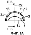
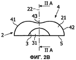
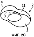
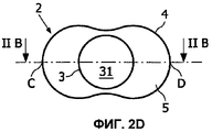
Фиг.2 представляет собой изображение в разных схематичных видах первого варианта осуществления оптического устройства согласно изобретению, а именно: прямой разрез (фиг.2А), продольный разрез (фиг.2В), перспективный вид сверху (фиг.2С) и вид в плане снизу (фиг.2D);Figure 2 is a view in different schematic views of a first embodiment of an optical device according to the invention, namely: a straight section (Fig. 2A), a longitudinal section (Fig. 2B), a perspective view from above (Fig. 2C) and a plan view from below (fig.2D);
Фиг.3 представляет собой перспективный вид снизу части уличного светильника, оснащенного оптическими устройствами согласно изобретению;Figure 3 is a perspective view from below of a part of a street lamp equipped with optical devices according to the invention;
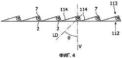
Фиг.4 представляет собой разрез части фиг.3 по плоскости IV-IV;FIG. 4 is a sectional view of a portion of FIG. 3 along a plane IV-IV;
Фиг.5 представляет собой изображение в разных схематичных видах второго варианта осуществления оптического устройства согласно изобретению, а именно: продольный разрез (фиг.5А) и вид в плане снизу (фиг.5В);Fig. 5 is a different schematic view of a second embodiment of an optical device according to the invention, namely: a longitudinal section (Fig. 5A) and a plan view from below (Fig. 5B);
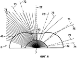
Фиг.6 представляет собой двухмерный путь, по которому следуют пучки света, испускаемые точечным источником света через оптическое устройство, как изображено на фиг.2.FIG. 6 is a two-dimensional path followed by light beams emitted by a point light source through an optical device, as shown in FIG.
Подробное описание изобретенияDETAILED DESCRIPTION OF THE INVENTION
В этом описании приняты следующие определения. Слова “улица”, “дорога”, “автомагистраль” и тому подобное должны истолковываться, как имеющие одинаковое значение.The following definitions are accepted in this description. The words “street”, “road”, “motorway” and the like should be construed as having the same meaning.
Диоптр является оптической поверхностью, которая разделяет две среды распространения света, имеющие разные показатели преломления. Примерами сред распространения света являются, например, воздух, стекло, полиметакрилат или другие пластики.A diopter is an optical surface that separates two light propagation media having different refractive indices. Examples of light propagation media are, for example, air, glass, polymethacrylate or other plastics.
Линза является устройством, которое заставляет свет либо сходиться, либо расходиться. Оно выполнено из куска профилированного материала, такого как стекло, полиметакрилат или другие пластики. Обычно линза имеет две поверхности или диоптра. Поверхность, или ее часть, может быть плоской (не изогнутой), выпуклой (выступающей наружу из линзы), или вогнутой (вдавленной в линзу).A lens is a device that makes light either converge or diverge. It is made of a piece of profiled material, such as glass, polymethacrylate or other plastics. Typically, a lens has two surfaces or a diopter. A surface, or part thereof, can be flat (not curved), convex (protruding outward from the lens), or concave (pressed into the lens).
Квадрика является поверхностью второго порядка. Например, сфера имеет квадрику.A quadric is a second-order surface. For example, a sphere has a quadric.
Метаповерхность является поверхностью меташара.The metasurface is the surface of the metashar.
Меташар определен, как изложено ниже. Каждый компонент Ci меташара может быть определен трехмерной математической функцией fi(x,y,z), где x,y,z являются координатами точки в пространстве. Выбирается пороговая величина Т. Для каждой точки (x,y,z) сумма S(x,y,z) вклада каждого компонента меташара вычисляется и сравнивается с пороговой величиной Т:The metashar is defined as follows. Each component C i of a meta ball can be defined by a three-dimensional mathematical function f i (x, y, z), where x, y, z are the coordinates of a point in space. The threshold value T is selected. For each point (x, y, z), the sum S (x, y, z) of the contribution of each metashar component is calculated and compared with the threshold value T:
![]()
![]()
Эта функция определяет скалярное поле. Если S(x,y,z) меньше, чем пороговая величина Т, то точка (x,y,z) находится внутри объема меташара; если S(x,y,z) равна пороговому значению Т, то точка (x,y,z) находится на поверхности меташара, то есть на метаповерхности. В противном случае, точка (x,y,z) находится снаружи меташара. Другими словами, следующее неравенство показывает объем, заключенный в меташаре, определяемом компонентами Ci:This function defines a scalar field. If S (x, y, z) is less than the threshold value T, then the point (x, y, z) is inside the metashar volume; if S (x, y, z) is equal to the threshold value of T, then the point (x, y, z) is located on the surface of the metashar, that is, on the metasurface. Otherwise, the point (x, y, z) is outside the metashar. In other words, the following inequality shows the volume enclosed in the metashar defined by the components C i :

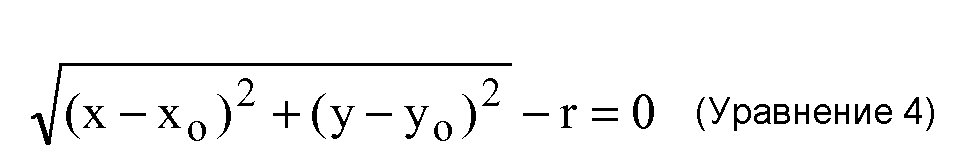
Сфера может быть представлена следующим уравнением, где (x0,y0,z0) являются координатами центра сферы, а r является радиусом сферы:A sphere can be represented by the following equation, where (x 0 , y 0 , z 0 ) are the coordinates of the center of the sphere, and r is the radius of the sphere:
![]()
![]()
Более того, цилиндр с осью z может быть представлен следующим уравнением, где r является радиусом цилиндра:Moreover, a cylinder with the z axis can be represented by the following equation, where r is the radius of the cylinder:
Хорошо известно, что S(x,y,z) может быть аппроксимирована полиномиальной функцией для ускорения вычисления меташара и метаповерхности. Дополнительные разработки, относящиеся к меташарам и метаповерхностям, могут быть найдены в Интернете.It is well known that S (x, y, z) can be approximated by a polynomial function to speed up the calculation of the meta ball and meta-surface. Additional developments related to meta-balls and metasurfaces can be found on the Internet.
Как указано выше, варианты осуществления изобретений относятся к оптическому устройству для придания световому лучу вытянутой формы. Упомянутое оптическое устройство содержит линзу, имеющую входной диоптр и выходной диоптр. Выходной диоптр содержит первую собирающую секцию, вторую собирающую секцию и рассеивающую секцию, соединяющую упомянутые первую и вторую собирающие секции. В предпочтительном варианте осуществления изобретения упомянутая рассеивающая секция гладко соединяет упомянутые первую и вторую собирающие секции выходного диоптра.As indicated above, embodiments of the invention relate to an optical device for giving the light beam an elongated shape. Said optical device comprises a lens having an input diopter and an output diopter. The output diopter comprises a first collecting section, a second collecting section and a scattering section connecting said first and second collecting sections. In a preferred embodiment, said scattering section smoothly connects said first and second collecting sections of the output diopter.
Предпочтительно, линза выполнена с возможностью формирования круглого светового луча в вытянутый световой луч, имеющий, по существу, однородную интенсивность света в продольном направлении. Это позволяет использовать такие источники света, как светоизлучающие диоды (LEDs), которые обычно испускают круглые световые лучи. Могут быть подходящими другие источники света. Однако преимущество светоизлучающих диодов заключается в том, что они являются миниатюрными источниками света. Таким образом, становится возможным создание тонких головок светильника, которые объединяют в себе множество светоизлучающих диодов, причем каждый светоизлучающий диод оснащен оптическим устройством согласно изобретению для формирования круглого светового луча в вытянутый световой луч. Например, светоизлучающие диоды и их соответствующие оптические устройства расположены во множестве линий и рядов. Посредством придания световому лучу подходящего направления, возможно направлять вытянутый световой луч к дороге и освещать ее, вместо того, чтобы светить прямо вниз под головку светильника. Более того, возможно помещать радиаторы за светоизлучающими диодами (то есть противоположно оптическому устройству относительно светоизлучающего диода), между линиями светоизлучающих диодов, как будет описано ниже, с минимальным влиянием на тонкость головки светильника. Более того, из-за высокой стоимости энергии высокоэффективные светоизлучающие диоды являются выгодными.Preferably, the lens is configured to form a circular light beam into an elongated light beam having a substantially uniform light intensity in the longitudinal direction. This allows the use of light sources such as light emitting diodes (LEDs), which usually emit round light rays. Other light sources may be suitable. However, the advantage of light emitting diodes is that they are miniature light sources. Thus, it becomes possible to create thin lamp heads that combine a plurality of light emitting diodes, each light emitting diode being equipped with an optical device according to the invention for forming a round light beam into an elongated light beam. For example, light emitting diodes and their respective optical devices are arranged in a plurality of lines and rows. By giving the light beam a suitable direction, it is possible to direct the elongated light beam toward the road and illuminate it, instead of shining directly down under the head of the lamp. Moreover, it is possible to place radiators behind the light emitting diodes (i.e., opposite to the optical device relative to the light emitting diode), between the lines of the light emitting diodes, as will be described below, with minimal effect on the thinness of the lamp head. Moreover, due to the high cost of energy, highly efficient light emitting diodes are advantageous.
На фиг.2 изображены разные виды первого варианта осуществления оптического устройства согласно изобретению. В этом первом варианте осуществления линза 2 имеет входной диоптр 3, являющийся вогнутым. Он может быть выполнен, как гнездо 31 для источника света. Общая форма входного диоптра не является существенным признаком линзы 2. Тем не менее, предпочтительно, если общая форма входного диоптра 3 является сферической или, по меньшей мере, является квадрикой. Действительно, такая форма имеет минимальное влияние на распределение пучков света. Это означает, что при прохождении через такой входной диоптр, особенно, через сферический диоптр, распределение пучков света остается, по существу, неизмененным.2 shows different views of a first embodiment of an optical device according to the invention. In this first embodiment, the
Как изображено на фиг.2, базовая поверхность 5 расположена у основания линзы 2, между входным диоптром 3 и выходным диоптром 4. Собственно говоря, базовая поверхность 5 также должна рассматриваться, как дополнительный диоптр, как таковой. Однако источник света предпочтительно должен быть расположен относительно входного диоптра 3, например, в гнезде 31, таким образом, чтобы свет от источника света не проходил через базовую поверхность 5. Это не означает, что совсем никакой свет не проходит через базовую поверхность 5, а просто то, что, по существу, весь свет, испускаемый источником света, направлен в сторону входного диоптра 3. Предпочтительно, если базовая поверхность 5, по существу, вписана в базовую плоскость. Это облегчает изготовление оптических устройств согласно изобретению, а так же сборку упомянутых оптических устройств в более крупных осветительных устройствах. Однако базовая поверхность может образовывать угол с плоскостью IIA (фиг.2В). Например, базовая поверхность может содержать две симметричные части, которые образуют угол с плоскостью IIA.As shown in figure 2, the
Предпочтительно, как изображено на фиг.2, если оптическое устройство согласно изобретению имеет две перпендикулярные плоскости симметрии IIA, IIB, которые также перпендикулярны к базовой плоскости, в которую вписана базовая поверхность 5. Плоскости IIA и IIB пересекаются по оси 22 линзы 2. Предпочтительно, если источник света расположен на оси 22 линзы 2. Предпочтительно, если упомянутое гнездо 31 имеет ось симметрии, которая проходит через упомянутый источник света.Preferably, as shown in FIG. 2, if the optical device according to the invention has two perpendicular planes of symmetry IIA, IIB, which are also perpendicular to the base plane into which the
Наиболее важна форма выходного диоптра 4 линзы 2. Действительно, в основном, форма выходного диоптра обуславливает распределение пучков света на выходе формирователя светового луча, и, таким образом, интенсивность выходного светового луча. При использовании круглого светового луча необходимо расширить его для придания ему вытянутой формы. Поэтому выходной диоптр 4 содержит первую собирающую секцию 41, вторую собирающую секцию 42 и рассеивающую секцию 43, соединяющую упомянутые первую и вторую собирающие секции 41, 42. Это позволяет диспергировать в направлении отдаленных собирающих секций 41, 42 круглый световой луч, который изначально сконцентрирован в направлении рассеивающей секции. Чем ближе собирающие секции 41, 42, тем более суженным будет выходной световой луч. Другими словами, рассеивающая секция 43 способствует расширению выходного светового луча, тогда как собирающие секции 41, 42 способствуют сужению выходного светового луча. Правильный баланс между ними обеспечивает удовлетворительную однородность света вдоль выходного светового луча.The most important form of the output diopter is 4
Лучшая однородность выходного светового луча может быть достигнута посредством симметрии линзы 2. Следовательно, предпочтительно, если выходной диоптр 41 содержит осесимметричную поверхность.Better uniformity of the output light beam can be achieved through the symmetry of
Например, как изображено на фиг.2, ось вращения 23 перпендикулярна оси 22 линзы 2 и вписана в плоскость симметрии IIB. При повороте кривой, содержащейся между точками C и D, вокруг оси 23 может быть получен весь выходной диоптр 4. Соответственно, это так же относится к входному диоптру 3, когда он имеет поверхность второго порядка, такую как сферическая поверхность.For example, as shown in FIG. 2, the axis of rotation 23 is perpendicular to the
В предпочтительном варианте осуществления изобретения упомянутые собирающие секции 41, 42 выходного диоптра 4 содержат поверхности второго порядка, такие как сферическая поверхность. В варианте осуществления, изображенном на фиг.2, собирающие секции 41, 42 являются выпуклыми и содержат сферические поверхности. Они вносят вклад в метаповерхность, которая также содержит цилиндрический вклад в разделяющей рассеивающей секции 43 так, что вся поверхность остается непрерывной, без разрыва уклона. Рассеивающая секция 43 получена из цилиндра, ось которого проходит по центру двух сфер, из которых получены собирающие секции 41, 42. В зависимости от желаемого применения высота этого цилиндра может быть равна или меньше, чем отдаленность двух упомянутых сфер. Для получения рассеивающей секции 43 радиус цилиндра должен быть меньше, чем радиусы сфер. В собирающих секциях наиболее важен вклад сфер в метаповерхность, тогда как в рассеивающей секции наиболее важен вклад цилиндра.In a preferred embodiment, said collecting
Обычно требуется, чтобы выходной световой луч был симметричным в продольном направлении, так как это касается интенсивности света. Следовательно, собирающие секции 41, 42 выходного диоптра 4 должны быть симметричными относительно друг друга, как изображено, например, на фиг.2В. Такое свойство также упрощает изготовление осветительного устройства, так как не существует вопроса правильной ориентации (влево или вправо) линзы.It is usually required that the output light beam be symmetrical in the longitudinal direction, as this relates to light intensity. Therefore, the collecting
На фиг.6 в двух измерениях изображен путь, по которому следуют пучки света, испускаемые точечным источником света через оптическое устройство, как изображено на фиг.2. Такой источник света, как правило, приводит к круглому световому лучу. Светоизлучающий диод 7 может быть приблизительно принят за точечный источник света.FIG. 6 shows, in two dimensions, the path that light beams emitted by a point light source through an optical device follow, as shown in FIG. Such a light source, as a rule, leads to a round light beam. The
На фиг.6 изображено действие линзы 2 на круглый световой луч, испускаемый светоизлучающим диодом 7, и сравнение результирующего вытянутого светового луча с круглым лучом света, который был бы получен без линзы 2. Обособлены две группы пучков света: пучки света, находящиеся у центра испущенного светового луча (то есть вблизи к оси 22 линзы 2), и пучки света, находящиеся у периферии светового луча. В иллюстративных целях, если ширина круглого светового луча измеряется согласно способу полной ширины и половинного максимума (full-width half-maximum method), который хорошо известен в данной области техники, то пучками света “у центра” светового луча могут быть те, которые имеют направление под углом к оси 22 меньшим, чем половина ширины круглого светового луча, тогда как пучками света “у периферии” светового луча могут быть те, которые имеют направление под углом к оси 22 большим, чем половина ширины круглого светового луча.Figure 6 shows the action of the
Центр светового луча, который был бы получен без оптического устройства 2, то есть через прямое распространение пучков 71 света, определен штрихпунктирными линиями 72. Штриховыми линиями 73 изображен световой луч, который получен после распространения таких же пучков света через линзу 2. Как может быть видно, центр светового луча расширен. Это значит, что центральный световой луч пересечет больше дорожной поверхности. Таким образом, ближайшая к источнику света дорожная поверхность получит меньше световой энергии на единицу поверхности, чем если это было бы достигнуто без линзы 2.The center of the light beam that would be obtained without the
Сравним с периферическим световым лучом: штрихпунктирными линиями 74 показан световой луч, полученный после прямого распространения; штриховыми линиями 75 показан световой луч, который получен после распространения таких же периферических пучков света через линзу 2. В случае периферических пучков света, световой луч, полученный после распространения через линзу 2, имеет меньшую ширину, чем без линзы 2. Более того, периферический световой луч находится ближе к оси 22 линзы 2. Это значит, что периферический световой луч будет пересекать меньше дорожной поверхности. Дорожная поверхность, которая освещена периферическим лучом света, то есть наиболее отдаленная от источника света, будет получать больше световой энергии на единицу поверхности.Compare with the peripheral light beam: dash-dotted
Это перераспределение светового луча обеспечивает лучшее освещение участка дороги вытянутым световым лучом.This redistribution of the light beam provides better illumination of the road section with an elongated light beam.
Выходной световой луч является настолько длинным, насколько возможно. Максимальное расстояние между двумя последующими уличными светильниками ограничено обязательными уровнями однородности освещения (для предотвращения ослепления пользователя дороги между яркими зонами и темными зонами) и интенсивности освещения (для обеспечения достаточного освещения) в направлении дороги. Ширина выходного светового луча также ограничена блескостью при больших углах и загрязнением неба.The output light beam is as long as possible. The maximum distance between two subsequent street lights is limited by the required levels of uniformity of lighting (to prevent the road user from being blinded between bright areas and dark areas) and the light intensity (to ensure sufficient lighting) in the direction of the road. The width of the output light beam is also limited by gloss at large angles and sky pollution.
Тем не менее может требоваться предусмотрение выходного светового луча, который на одной стороне более интенсивен или менее вытянут, чем на противоположной стороне. В этом случае собирающая секция выходного диоптра может быть меньше, чем противоположная собирающая секция. Плоскость IIA больше не будет рассматриваться, как плоскость симметрии. Чем крупнее собирающая секция, тем более диспергированными будут пучки света, результатом чего будет менее интенсивный световой луч и более вытянутый световой луч. Другим решением может быть расположение источника света не на оси 22 линзы, а, например, на линии, параллельной оси 22 вдоль оси вращения 23. Конечно же оба решения могут быть объединены вместе.However, it may be necessary to provide an output light beam that is on one side more intense or less elongated than on the opposite side. In this case, the collecting section of the output diopter may be smaller than the opposite collecting section. The IIA plane will no longer be considered a plane of symmetry. The larger the collecting section, the more dispersed the light beams will be, resulting in a less intense light beam and a more elongated light beam. Another solution may be to position the light source not on the
На фиг.5 изображен еще один другой вариант осуществления оптического устройства согласно изобретению. В этом варианте осуществления линза 200 содержит два входных диоптра 301, 302, которые, например, симметричны относительно друг друга. Каждый входной диоптр может быть выполнен в качестве гнезда 311, 312 для источника света, такого как светоизлучающий диод. Как изображено, входные диоптры имеют сферическую поверхность, но это не является обязательным, как описано выше. Источники света предпочтительно расположены вдоль осей 221, 222 входных диоптров 301, 302. Выходной диоптр 400 содержит три собирающие секции 401, 402, 403 и две рассеивающие секции 404, 405. Рассеивающая секция 404 соединяет собирающие секции 401 и 402. Рассеивающая секция 405 соединяет собирающие секции 402 и 403. Выходной диоптр 400 осесимметричен вокруг оси вращения 230. Он содержит метаповерхность, которая получена из комбинаций сфер (собирающих секций) и цилиндров (рассеивающих секций).Figure 5 shows another another embodiment of an optical device according to the invention. In this embodiment, the lens 200 contains two input diopters 301, 302, which, for example, are symmetrical with respect to each other. Each input diopter may be configured as a socket 311, 312 for a light source, such as a light emitting diode. As shown, the input diopters have a spherical surface, but this is not necessary, as described above. The light sources are preferably located along the axes 221, 222 of the input diopters 301, 302. The output diopter 400 includes three collecting sections 401, 402, 403 and two diffusing sections 404, 405. The diffusing section 404 connects the collecting sections 401 and 402. The diffusing section 405 connects the collecting sections 402 and 403. The output diopter 400 is axisymmetric about the axis of rotation 230. It contains a metasurface, which is obtained from combinations of spheres (collecting sections) and cylinders (scattering sections).
Такая линза 200 может быть использована, например, для смешивания цветов. В этом случае выбираются источники света с разными цветами. С использованием варианта осуществления, изображенного на фиг.5, цвет выходного светового луча будет постоянно меняться в продольном направлении выходного светового луча по существу от цвета источника света, расположенного в гнезде 311, до цвета источника света, расположенного в гнезде 312.Such a lens 200 can be used, for example, for mixing colors. In this case, light sources with different colors are selected. Using the embodiment shown in FIG. 5, the color of the output light beam will constantly change in the longitudinal direction of the output light beam essentially from the color of the light source located in the socket 311 to the color of the light source located in the socket 312.
Линза 200, изображенная на фиг.5, также может быть использована для упрощения изготовления: только одна линза необходима для формирования светового луча, испускаемого двумя источниками света.The lens 200 shown in FIG. 5 can also be used to simplify manufacturing: only one lens is needed to form a light beam emitted by two light sources.
Если требуется получить смешивание цветов, однородное в продольном направлении выходного светового луча, тогда может быть спроектировано более сложное оптическое устройство с тремя входными диоптрами: в центральном входном диоптре будет расположен источник света, имеющий первый цвет, и в каждом из двух боковых входных диоптров будет расположен источник света, имеющий второй цвет.If you want to obtain color mixing that is uniform in the longitudinal direction of the output light beam, then a more complex optical device with three input diopters can be designed: a light source having a first color will be located in the central input diopter and each of the two side input diopters will be located a light source having a second color.
В дополнительном варианте осуществления вместо того, чтобы быть установленными на одной прямой, собирающие секции выходных диоптров линзы расположены у углов квадрата с рассеивающими секциями, соединяющими последовательные углы или противоположные углы, или как последовательные, так и противоположные углы. Такая линза будет придавать лучу света вытянутую крестообразную форму.In an additional embodiment, instead of being mounted on one straight line, the collecting sections of the output diopters of the lens are located at the corners of the square with scattering sections connecting successive angles or opposite angles, or both sequential and opposite angles. Such a lens will give the beam of light an elongated cruciform shape.
Обычно линзы 2, 200 изготавливаются посредством формования под давлением или инжекционного формования согласно хорошо известным способам. Они предпочтительно изготавливаются с использованием прозрачного материала. Этот материал может быть цветным или бесцветным в зависимости от требуемого применения. Например, подходящим материалом является полиметакрилат, в особенности, поли(метилметакрилат). Могут быть использованы другие прозрачные пластики, такие как поликарбонаты.Typically,
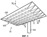
На фиг.3 и 4 изображен в различных видах уличный светильник 11, оснащенный оптическими устройствами согласно варианту осуществления изобретения. Как может быть видно на фиг.3, головка 112 светильника, видимая снизу, предусмотрена на вершине столба 111 светильника (частичный вид). Головка 112 светильника содержит суппорт 113 для множества осветительных устройств 6. Упомянутые осветительные устройства 6 расположены под суппортом 113 головки 112 светильника и направлены в сторону земли, а именно, в сторону улицы. Осветительные устройства могут быть расположены, как изображено на фиг.3, в линиях и рядах.Figures 3 and 4 show, in various forms, a
Каждое осветительное устройство 6 содержит светоизлучающий диод 7, расположенный вверх по потоку оптического устройства 2 относительно распространения света. Оптическое устройство было подробно описано выше в описании. Например, используются такие оптические устройства, как в варианте осуществления, изображенном на фиг.2. Светоизлучающие диоды 7 имеют источник энергии, который не изображен.Each
Светоизлучающие диоды являются хорошей альтернативой стандартным источникам света, используемым для уличного освещения. Большое количество светоизлучающих диодов может быть установлено на каждой головке светильника для обеспечения достаточного освещения. Для обеспечения привлекательности продукта размеры головки светильника должны оставаться достаточно малыми.Light emitting diodes are a good alternative to the standard light sources used for street lighting. A large number of light-emitting diodes can be installed on each head of the lamp to ensure sufficient lighting. To ensure the attractiveness of the product, the dimensions of the lamp head must remain small enough.
Одним из преимуществ светоизлучающих диодов является миниатюризация. При применениях на открытом пространстве это обеспечивает уменьшенную толщину головки светильника с миниатюризированной оптикой. Изобретение предлагает оптику для светоизлучающих диодов, простую для проектирования и для выполнения с возможностью использования в большом диапазоне конфигураций, и обеспечивает вытянутый луч для уличного освещения с высокой эффективностью, которая сравнима с эффективностью классической ротационной оптики, используемой для большой площади, с меньшими размерами и возможностью обеспечения пониженного загрязнения неба.One of the advantages of light emitting diodes is miniaturization. For outdoor applications this provides reduced head thickness with miniaturized optics. The invention provides optics for light-emitting diodes that are simple to design and can be used in a wide range of configurations, and provides an elongated beam for street lighting with high efficiency, which is comparable to the efficiency of classical rotational optics used for a large area, with smaller dimensions and the possibility of providing reduced sky pollution.
Для правильного освещения зоны улицы все осветительные устройства имеют одинаковое направление, то есть, направление света LD образует угол «тета» с вертикальным направлением V. Таким образом, возможно определить углубление 114 в суппорте 113 между двумя последовательными рядами осветительных устройств. Это углубление 114 выполнено с возможностью вмещения множества радиаторов (не изображены), которые являются полезными для отвода и рассеивания тепла, которое выделяется во время работы светоизлучающих диодов. Поскольку радиаторы вмещены в углубление 114, головки светильника остаются тонкими, что является желательным.To properly illuminate the street zone, all lighting devices have the same direction, that is, the direction of light LD forms the theta angle with the vertical direction V. Thus, it is possible to define a
Никакая ссылка в последующих пунктах формулы изобретения не должна пониматься, как ограничивающая формулу изобретения. Будет очевидно, что применение глагола “содержать” и его спряжений не исключает наличия любых других элементов, кроме тех, которые определены в любом пункте формулы изобретения. Форма единственного числа элемента не исключает наличия множества таких элементов.No reference in the following claims should be understood as limiting the claims. It will be obvious that the use of the verb “contain” and its conjugations does not exclude the presence of any other elements except those defined in any claim. The singular form of an element does not exclude the presence of a plurality of such elements.
Claims (19)
(i) входной диоптр (3, 301, 302) и
(ii) выходной диоптр (4, 400), который содержит первую собирающую секцию (41, 401), вторую собирающую секцию (42, 402, 403) и рассеивающую секцию (43, 404), соединяющую упомянутые первую и вторую собирающие секции, причем выходной диоптр содержит осесимметричную непрерывную поверхность, выполненную вокруг оси вращения (23), перпендикулярной к упомянутой оси.1. An optical device for giving the light beam an elongated shape, containing a lens (2) having an axis (22, 221, 222) and:
(i) the input diopter (3, 301, 302) and
(ii) an output diopter (4, 400), which comprises a first collecting section (41, 401), a second collecting section (42, 402, 403) and a diffusing section (43, 404) connecting said first and second collecting sections, wherein the output diopter contains an axisymmetric continuous surface made around an axis of rotation (23) perpendicular to said axis.
Applications Claiming Priority (2)
| Application Number | Priority Date | Filing Date | Title |
|---|---|---|---|
| EP07300925 | 2007-04-05 | ||
| EP07300925.0 | 2007-04-05 |
Publications (2)
| Publication Number | Publication Date |
|---|---|
| RU2009140774A RU2009140774A (en) | 2011-05-10 |
| RU2456503C2 true RU2456503C2 (en) | 2012-07-20 |
Family
ID=39683718
Family Applications (1)
| Application Number | Title | Priority Date | Filing Date |
|---|---|---|---|
| RU2009140774/28A RU2456503C2 (en) | 2007-04-05 | 2008-04-04 | Light beam former |
Country Status (9)
| Country | Link |
|---|---|
| US (1) | US8220958B2 (en) |
| EP (1) | EP2135005B1 (en) |
| JP (3) | JP5349453B2 (en) |
| CN (2) | CN103822172B (en) |
| AT (1) | ATE483939T1 (en) |
| DE (1) | DE602008002911D1 (en) |
| ES (1) | ES2353936T3 (en) |
| RU (1) | RU2456503C2 (en) |
| WO (1) | WO2008122941A1 (en) |
Cited By (3)
| Publication number | Priority date | Publication date | Assignee | Title |
|---|---|---|---|---|
| RU2543528C2 (en) * | 2013-05-17 | 2015-03-10 | Общество С Ограниченной Ответственностью "Новые Энергетические Технологии" | Optical system for secondary light-emitting diode optics |
| RU2674263C1 (en) * | 2017-10-27 | 2018-12-06 | Акционерное общество "Научно-исследовательский институт телевидения" | Led illuminator |
| RU220099U1 (en) * | 2022-12-05 | 2023-08-24 | Общество с ограниченной ответственностью Лихославльский завод светотехнических изделий "Светотехника" | STREET LIGHT WITH ADJUSTABLE ANGLE |
Families Citing this family (122)
| Publication number | Priority date | Publication date | Assignee | Title |
|---|---|---|---|---|
| US20050259424A1 (en) | 2004-05-18 | 2005-11-24 | Zampini Thomas L Ii | Collimating and controlling light produced by light emitting diodes |
| US7766511B2 (en) | 2006-04-24 | 2010-08-03 | Integrated Illumination Systems | LED light fixture |
| US7729941B2 (en) | 2006-11-17 | 2010-06-01 | Integrated Illumination Systems, Inc. | Apparatus and method of using lighting systems to enhance brand recognition |
| US8013538B2 (en) | 2007-01-26 | 2011-09-06 | Integrated Illumination Systems, Inc. | TRI-light |
| US8742686B2 (en) | 2007-09-24 | 2014-06-03 | Integrated Illumination Systems, Inc. | Systems and methods for providing an OEM level networked lighting system |
| DE102008006229B4 (en) | 2008-01-25 | 2013-08-29 | We-Ef Leuchten Gmbh & Co. Kg | Street lighting device |
| DE102008016496A1 (en) * | 2008-03-31 | 2009-10-01 | Zumtobel Lighting Gmbh | Luminaire with punctiform light source and asymmetrical light emission characteristic |
| US8255487B2 (en) | 2008-05-16 | 2012-08-28 | Integrated Illumination Systems, Inc. | Systems and methods for communicating in a lighting network |
| TWI381134B (en) * | 2008-06-02 | 2013-01-01 | 榮創能源科技股份有限公司 | Led lighting module |
| WO2010057311A1 (en) | 2008-11-21 | 2010-05-27 | Dbm Reflex Entreprises Inc. | Solid state optical illumination apparatus |
| JP5241015B2 (en) * | 2009-01-29 | 2013-07-17 | パナソニック株式会社 | Optical lens and road lighting |
| JP5336879B2 (en) * | 2009-02-23 | 2013-11-06 | 日東光学株式会社 | Optical element, light emitting device and road light |
| US8293548B2 (en) * | 2009-03-04 | 2012-10-23 | Unilumin Group Co., Ltd. | LED light module for street lamp and method of manufacturing same |
| CN101514806A (en) | 2009-03-04 | 2009-08-26 | 深圳市洲明科技有限公司 | LED light-emitting unit for street lamp |
| JP5257609B2 (en) * | 2009-03-04 | 2013-08-07 | スタンレー電気株式会社 | Optical module and lighting fixture |
| CN101852385A (en) * | 2009-04-01 | 2010-10-06 | 香港理工大学 | Light distribution lens for LED street light |
| US8585245B2 (en) | 2009-04-23 | 2013-11-19 | Integrated Illumination Systems, Inc. | Systems and methods for sealing a lighting fixture |
| DE102010004221A1 (en) * | 2009-05-05 | 2010-11-11 | Siteco Beleuchtungstechnik Gmbh | Street light with punctiform light sources, in particular LED light |
| IT1400377B1 (en) * | 2009-07-20 | 2013-05-31 | Fivep S P A | LED LIGHTING DEVICE |
| US8662704B2 (en) * | 2009-08-14 | 2014-03-04 | U.S. Pole Company, Inc. | LED optical system with multiple levels of secondary optics |
| CN102032526B (en) * | 2009-09-30 | 2013-08-07 | 富准精密工业(深圳)有限公司 | LED module |
| US9039252B2 (en) | 2009-10-08 | 2015-05-26 | Koninklijkle Philips N.V. | Lens for asymmetrical light beam generation |
| WO2011083386A1 (en) | 2010-01-05 | 2011-07-14 | Koninklijke Philips Electronics N.V. | Removable light engine |
| JP5313181B2 (en) * | 2010-01-26 | 2013-10-09 | パナソニック株式会社 | Lighting device |
| US8891171B2 (en) * | 2010-02-01 | 2014-11-18 | Dbm Reflex Enterprises Inc. | High sag thick lens for use in an illumination apparatus |
| EP2531345B1 (en) * | 2010-02-01 | 2019-04-03 | DBM Reflex Enterprises Inc. | Lens molded with embedded layers of the same resin using a two step injection molding process. |
| DE102010001860A1 (en) * | 2010-02-11 | 2011-08-11 | ewo srl/Gmbh, BZ | Lighting module for traffic route lighting and traffic route light |
| DE102010021452A1 (en) * | 2010-04-01 | 2011-10-06 | Siteco Beleuchtungstechnik Gmbh | Luminaire with LED modules |
| DE102010014099A1 (en) * | 2010-04-07 | 2011-10-13 | Siteco Beleuchtungstechnik Gmbh | Luminaire with cover |
| KR101047439B1 (en) * | 2010-04-09 | 2011-07-08 | 엘지이노텍 주식회사 | Illumination unit with lens and lens |
| FR2963085A1 (en) * | 2010-07-22 | 2012-01-27 | Holophane | LENS AND LIGHTING MODULE USING SUCH A LENS. |
| FR2963084A1 (en) * | 2010-07-22 | 2012-01-27 | Holophane | LENS AND LIGHTING MODULE USING SUCH A LENS. |
| ITVR20100153A1 (en) * | 2010-07-26 | 2012-01-27 | Aldo Alberti | DIFFUSION LENS FOR SPREADING LIGHT EMITTED BY A PUNCTUAL SOURCE |
| WO2012029711A1 (en) * | 2010-08-31 | 2012-03-08 | 東芝ライテック株式会社 | Lens, lighting system, bulb-shaped lamp, and lighting fixture |
| TWI443382B (en) * | 2010-08-31 | 2014-07-01 | Wintek Corp | Illumination device and lens thereof |
| WO2012080889A1 (en) | 2010-12-16 | 2012-06-21 | Koninklijke Philips Electronics N.V. | Optical device for a led illumination apparatus shaping an elongated illuminated area |
| EP2652390B1 (en) | 2010-12-16 | 2014-04-23 | Koninklijke Philips N.V. | Led-based assembly |
| JP5409595B2 (en) * | 2010-12-24 | 2014-02-05 | 三菱電機株式会社 | Lighting device |
| WO2012090108A1 (en) * | 2010-12-30 | 2012-07-05 | Koninklijke Philips Electronics N.V. | A lens and a lighting apparatus comprising such a lens. |
| KR101211731B1 (en) * | 2010-12-30 | 2012-12-12 | 엘지이노텍 주식회사 | Secondary Optical Lens for Lamp |
| US9066381B2 (en) | 2011-03-16 | 2015-06-23 | Integrated Illumination Systems, Inc. | System and method for low level dimming |
| JP5626059B2 (en) * | 2011-03-23 | 2014-11-19 | 市光工業株式会社 | Vehicle lighting |
| RU2612562C2 (en) | 2011-05-05 | 2017-03-09 | Филипс Лайтинг Холдинг Б.В. | Optical device for generating light beam |
| US9967940B2 (en) | 2011-05-05 | 2018-05-08 | Integrated Illumination Systems, Inc. | Systems and methods for active thermal management |
| CN102818215A (en) * | 2011-06-07 | 2012-12-12 | 富准精密工业(深圳)有限公司 | Lens and lighting device |
| US8641234B2 (en) | 2011-06-30 | 2014-02-04 | Groupe Ledel Inc. | Lamppost head assembly with adjustable LED heat sink support |
| US11917740B2 (en) | 2011-07-26 | 2024-02-27 | Hunter Industries, Inc. | Systems and methods for providing power and data to devices |
| US10874003B2 (en) | 2011-07-26 | 2020-12-22 | Hunter Industries, Inc. | Systems and methods for providing power and data to devices |
| US8710770B2 (en) | 2011-07-26 | 2014-04-29 | Hunter Industries, Inc. | Systems and methods for providing power and data to lighting devices |
| US20150237700A1 (en) | 2011-07-26 | 2015-08-20 | Hunter Industries, Inc. | Systems and methods to control color and brightness of lighting devices |
| US9609720B2 (en) | 2011-07-26 | 2017-03-28 | Hunter Industries, Inc. | Systems and methods for providing power and data to lighting devices |
| US9521725B2 (en) | 2011-07-26 | 2016-12-13 | Hunter Industries, Inc. | Systems and methods for providing power and data to lighting devices |
| TWI463095B (en) * | 2011-09-23 | 2014-12-01 | Univ Nat Yunlin Sci & Tech | Rectangular light of the LED secondary optical lampshade |
| US9234649B2 (en) | 2011-11-01 | 2016-01-12 | Lsi Industries, Inc. | Luminaires and lighting structures |
| ITMI20112064A1 (en) * | 2011-11-14 | 2013-05-15 | Gewiss Spa | MODULAR LED LIGHTING DEVICE, PARTICULARLY FOR ROAD AND SIMILAR LAMPS |
| KR101167045B1 (en) | 2011-12-30 | 2012-07-27 | 주식회사 대진디엠피 | Aspherical lens and aspherical lens having thereof |
| DE102012000388A1 (en) | 2012-01-11 | 2013-07-11 | Bartenbach Holding Gmbh | lamp |
| KR101458671B1 (en) | 2012-06-26 | 2014-11-06 | (주)보임기술 | LED type flat panel display ads, and applied to the image of a rectangular shape with a aspherical lens |
| US8894437B2 (en) | 2012-07-19 | 2014-11-25 | Integrated Illumination Systems, Inc. | Systems and methods for connector enabling vertical removal |
| US8974077B2 (en) | 2012-07-30 | 2015-03-10 | Ultravision Technologies, Llc | Heat sink for LED light source |
| TWI506229B (en) * | 2012-09-12 | 2015-11-01 | Coretronic Corp | Light emitting apparatus and lens |
| CN103672728B (en) * | 2012-09-13 | 2017-09-08 | 赛尔富电子有限公司 | Lens, LED modules and the illuminator using the LED modules |
| TW201416619A (en) * | 2012-10-19 | 2014-05-01 | Hon Hai Prec Ind Co Ltd | Lens and light source module having the same |
| CN204964862U (en) * | 2012-11-05 | 2016-01-13 | 皇家飞利浦有限公司 | Optical element, optical assembly, lighting device and luminaire for modifying the spatial distribution of light emitted by a light source to provide an elongated light beam elongated in a first direction |
| US9379578B2 (en) | 2012-11-19 | 2016-06-28 | Integrated Illumination Systems, Inc. | Systems and methods for multi-state power management |
| US9420665B2 (en) | 2012-12-28 | 2016-08-16 | Integration Illumination Systems, Inc. | Systems and methods for continuous adjustment of reference signal to control chip |
| US9485814B2 (en) | 2013-01-04 | 2016-11-01 | Integrated Illumination Systems, Inc. | Systems and methods for a hysteresis based driver using a LED as a voltage reference |
| KR101458686B1 (en) | 2013-01-29 | 2014-11-06 | (주)보임기술 | Aspheric lens with rectangular light distribution spread for display |
| US9291320B2 (en) | 2013-01-30 | 2016-03-22 | Cree, Inc. | Consolidated troffer |
| US9366396B2 (en) | 2013-01-30 | 2016-06-14 | Cree, Inc. | Optical waveguide and lamp including same |
| US10436969B2 (en) | 2013-01-30 | 2019-10-08 | Ideal Industries Lighting Llc | Optical waveguide and luminaire incorporating same |
| US9442243B2 (en) | 2013-01-30 | 2016-09-13 | Cree, Inc. | Waveguide bodies including redirection features and methods of producing same |
| US9869432B2 (en) | 2013-01-30 | 2018-01-16 | Cree, Inc. | Luminaires using waveguide bodies and optical elements |
| US9625638B2 (en) | 2013-03-15 | 2017-04-18 | Cree, Inc. | Optical waveguide body |
| TW201435397A (en) * | 2013-03-05 | 2014-09-16 | Hon Hai Prec Ind Co Ltd | Lens and light emitting diode package structure using the same |
| US9192026B2 (en) | 2013-03-14 | 2015-11-17 | Abl Ip Holding Llc | Veiling zone control |
| US9192029B2 (en) * | 2013-03-14 | 2015-11-17 | Abl Ip Holding Llc | Adaptive optical distribution system |
| US9798072B2 (en) | 2013-03-15 | 2017-10-24 | Cree, Inc. | Optical element and method of forming an optical element |
| US10502899B2 (en) * | 2013-03-15 | 2019-12-10 | Ideal Industries Lighting Llc | Outdoor and/or enclosed structure LED luminaire |
| US10379278B2 (en) * | 2013-03-15 | 2019-08-13 | Ideal Industries Lighting Llc | Outdoor and/or enclosed structure LED luminaire outdoor and/or enclosed structure LED luminaire having outward illumination |
| US10209429B2 (en) | 2013-03-15 | 2019-02-19 | Cree, Inc. | Luminaire with selectable luminous intensity pattern |
| US9366799B2 (en) | 2013-03-15 | 2016-06-14 | Cree, Inc. | Optical waveguide bodies and luminaires utilizing same |
| TWI572952B (en) * | 2013-08-22 | 2017-03-01 | 鴻海精密工業股份有限公司 | Led element and backlight module using the same |
| JP6224451B2 (en) * | 2013-12-16 | 2017-11-01 | 浜井電球工業株式会社 | LED light distribution control lens |
| US9651740B2 (en) | 2014-01-09 | 2017-05-16 | Cree, Inc. | Extraction film for optical waveguide and method of producing same |
| JP2015187671A (en) * | 2014-03-27 | 2015-10-29 | 一詮精密工業股▲ふん▼有限公司 | Optical element |
| RU2672643C2 (en) | 2014-03-28 | 2018-11-16 | Асахи Раббер Инк. | Light distribution lens |
| US9541255B2 (en) | 2014-05-28 | 2017-01-10 | Lsi Industries, Inc. | Luminaires and reflector modules |
| US12372219B2 (en) * | 2014-05-30 | 2025-07-29 | Cree Lighting Usa Llc | LED luminaire with a cavity, finned interior, and a curved outer wall extending from a surface on which the light source is mounted |
| US10039174B2 (en) | 2014-08-11 | 2018-07-31 | RAB Lighting Inc. | Systems and methods for acknowledging broadcast messages in a wireless lighting control network |
| US10085328B2 (en) | 2014-08-11 | 2018-09-25 | RAB Lighting Inc. | Wireless lighting control systems and methods |
| US10531545B2 (en) | 2014-08-11 | 2020-01-07 | RAB Lighting Inc. | Commissioning a configurable user control device for a lighting control system |
| US9883567B2 (en) | 2014-08-11 | 2018-01-30 | RAB Lighting Inc. | Device indication and commissioning for a lighting control system |
| US9606229B2 (en) * | 2014-09-29 | 2017-03-28 | Honeywell International Inc. | Highly efficient NIR light distribution for imaging based intrusion detection |
| US10228711B2 (en) | 2015-05-26 | 2019-03-12 | Hunter Industries, Inc. | Decoder systems and methods for irrigation control |
| US10918030B2 (en) | 2015-05-26 | 2021-02-16 | Hunter Industries, Inc. | Decoder systems and methods for irrigation control |
| US10030844B2 (en) | 2015-05-29 | 2018-07-24 | Integrated Illumination Systems, Inc. | Systems, methods and apparatus for illumination using asymmetrical optics |
| US10060599B2 (en) | 2015-05-29 | 2018-08-28 | Integrated Illumination Systems, Inc. | Systems, methods and apparatus for programmable light fixtures |
| KR102410450B1 (en) * | 2015-06-01 | 2022-06-20 | 루미리즈 홀딩 비.브이. | Lenses with an elongated radiation pattern |
| WO2017032585A1 (en) * | 2015-08-21 | 2017-03-02 | Philips Lighting Holding B.V. | Optical lens with tooth structure |
| DE102015114653A1 (en) | 2015-09-02 | 2017-03-02 | Lighting Innovation Group Ag | Optics arrangement for providing a lighting distribution |
| CN108139519B (en) | 2015-09-08 | 2021-09-07 | 华盛顿大学 | Low-contrast silicon nitride-based metasurfaces |
| DE102016103288A1 (en) | 2016-02-24 | 2017-08-24 | Siteco Beleuchtungstechnik Gmbh | Luminaire module especially for street lights |
| US10416377B2 (en) | 2016-05-06 | 2019-09-17 | Cree, Inc. | Luminaire with controllable light emission |
| US11719882B2 (en) | 2016-05-06 | 2023-08-08 | Ideal Industries Lighting Llc | Waveguide-based light sources with dynamic beam shaping |
| US10234094B2 (en) * | 2016-09-13 | 2019-03-19 | Valeo North America, Inc. | Lighting device for producing a supplemental beam |
| EP3415812A1 (en) | 2017-06-13 | 2018-12-19 | Philips Lighting Holding B.V. | A lens for a light source, for providing an asymmetric output, and a lighting unit using the lens |
| US10274159B2 (en) | 2017-07-07 | 2019-04-30 | RAB Lighting Inc. | Lenses and methods for directing light toward a side of a luminaire |
| CN107340552A (en) * | 2017-08-22 | 2017-11-10 | 广州创维平面显示科技有限公司 | A kind of lens and down straight aphototropism mode set |
| US20190120460A1 (en) * | 2017-10-23 | 2019-04-25 | David Gerard Pelka | Horticultural led illuminator |
| US11346542B2 (en) * | 2019-06-13 | 2022-05-31 | Apple Inc. | Electronic device with diffusively illuminated housing portions |
| US10801714B1 (en) | 2019-10-03 | 2020-10-13 | CarJamz, Inc. | Lighting device |
| US11175017B2 (en) * | 2019-10-31 | 2021-11-16 | Robe Lighting S.R.O. | System and method for producing a blending light distribution from LED luminaires |
| WO2021209492A1 (en) * | 2020-04-15 | 2021-10-21 | CommScope Connectivity Belgium BV | Device and method for sealing cables in telecommunications enclosures |
| JP7315858B2 (en) | 2021-02-17 | 2023-07-27 | 日亜化学工業株式会社 | light emitting device |
| US12050006B2 (en) | 2022-03-04 | 2024-07-30 | Abl Ip Holding Llc | Optic with total internal reflection refractor for back light control |
| USD1011603S1 (en) | 2022-03-04 | 2024-01-16 | Abl Ip Holding Llc | Optic |
| JP7648025B2 (en) * | 2022-06-22 | 2025-03-18 | 株式会社光波 | Lens, light source device and display device |
| CN115899614B (en) * | 2022-11-09 | 2025-10-31 | 上海天马微电子有限公司 | Light guide plate assembly, backlight module and display device |
| US12416908B2 (en) | 2022-12-29 | 2025-09-16 | Integrated Illumination Systems, Inc. | Systems and methods for manufacturing light fixtures |
| US12297996B2 (en) | 2023-02-16 | 2025-05-13 | Integrated Illumination Systems, Inc. | Cove light fixture with hidden integrated air return |
| CN121254537A (en) * | 2025-12-05 | 2026-01-02 | 华域视觉科技(上海)有限公司 | Liquid crystal display device, car lamp and vehicle |
Citations (4)
| Publication number | Priority date | Publication date | Assignee | Title |
|---|---|---|---|---|
| RU2079044C1 (en) * | 1992-12-21 | 1997-05-10 | Ханечка Мирослав | Lighting system for optical elements, projectors and photographic enlarger |
| US5692827A (en) * | 1996-03-01 | 1997-12-02 | Ford Motor Company | Tail lamp for an automotive vehicle using an elongated hyperbolic cylinder |
| DE10204481A1 (en) * | 2002-02-05 | 2003-08-14 | Automotive Lighting Reutlingen | Headlight comprises at least one light source, at least two transparent end elements with light entry and exit planes and at least one lens interacting with the light exit plane of the end element |
| EP1621918A1 (en) * | 2004-07-20 | 2006-02-01 | Osram Opto Semiconductors GmbH | Optical element comprising a beam exit surface with concave and convex portions allowing for uniform illumination of a given area with an arragement of light emitting diodes |
Family Cites Families (114)
| Publication number | Priority date | Publication date | Assignee | Title |
|---|---|---|---|---|
| BE532581A (en) | 1954-01-29 | |||
| US3711722A (en) | 1958-07-28 | 1973-01-16 | American Optical Corp | Detecting systems and the like |
| US3596136A (en) | 1969-05-13 | 1971-07-27 | Rca Corp | Optical semiconductor device with glass dome |
| US3774021A (en) | 1972-05-25 | 1973-11-20 | Bell Telephone Labor Inc | Light emitting device |
| CH618654A5 (en) | 1976-09-17 | 1980-08-15 | Erni & Co Elektro Ind | |
| JPS59204815A (en) * | 1983-05-09 | 1984-11-20 | Yamagata Daigaku | Averaging lens of illuminance for illumination |
| HU195593B (en) | 1985-10-01 | 1988-05-30 | Tungsram Reszvenytarsasag | Light-source, preferably for public lighting and industrial applications |
| US5140220A (en) | 1985-12-02 | 1992-08-18 | Yumi Sakai | Light diffusion type light emitting diode |
| US4698730A (en) | 1986-08-01 | 1987-10-06 | Stanley Electric Co., Ltd. | Light-emitting diode |
| US4860177A (en) | 1988-01-25 | 1989-08-22 | John B. Simms | Bicycle safety light |
| US4941072A (en) | 1988-04-08 | 1990-07-10 | Sanyo Electric Co., Ltd. | Linear light source |
| US5013144A (en) | 1988-10-15 | 1991-05-07 | Hewlett-Packard Company | Light source having a multiply conic lens |
| US5130897A (en) | 1991-10-31 | 1992-07-14 | At&T Bell Laboratories | Light guide for a telephone dial |
| US5335157A (en) | 1992-01-07 | 1994-08-02 | Whelen Technologies, Inc. | Anti-collision light assembly |
| IT1265106B1 (en) | 1993-07-23 | 1996-10-30 | Solari Udine Spa | OPTICAL SYSTEM FOR LIGHT-EMITTING DIODES |
| US5481440A (en) | 1993-12-27 | 1996-01-02 | At&T Corp. | Circuit pack with light pipes |
| US5608290A (en) | 1995-01-26 | 1997-03-04 | Dominion Automotive Group, Inc. | LED flashing lantern |
| US5636057A (en) | 1995-02-10 | 1997-06-03 | Ecolux Inc. | Prismatic toroidal lens and traffic signal light using this lens |
| JP3076966B2 (en) | 1996-06-14 | 2000-08-14 | スタンレー電気株式会社 | Light emitting diode element |
| US6045240A (en) | 1996-06-27 | 2000-04-04 | Relume Corporation | LED lamp assembly with means to conduct heat away from the LEDS |
| US6177761B1 (en) | 1996-07-17 | 2001-01-23 | Teledyne Lighting And Display Products, Inc. | LED with light extractor |
| US6227685B1 (en) | 1996-10-11 | 2001-05-08 | Mcdermott Kevin | Electronic wide angle lighting device |
| TW330233B (en) | 1997-01-23 | 1998-04-21 | Philips Eloctronics N V | Luminary |
| US7014336B1 (en) | 1999-11-18 | 2006-03-21 | Color Kinetics Incorporated | Systems and methods for generating and modulating illumination conditions |
| JP2980121B2 (en) | 1997-09-22 | 1999-11-22 | 日亜化学工業株式会社 | Light emitting diode for signal and traffic light using the same |
| US6273596B1 (en) | 1997-09-23 | 2001-08-14 | Teledyne Lighting And Display Products, Inc. | Illuminating lens designed by extrinsic differential geometry |
| US5924788A (en) | 1997-09-23 | 1999-07-20 | Teledyne Lighting And Display Products | Illuminating lens designed by extrinsic differential geometry |
| JP3185977B2 (en) | 1998-08-12 | 2001-07-11 | スタンレー電気株式会社 | LED lamp |
| US6361191B1 (en) | 1998-09-29 | 2002-03-26 | Jerome H. Simon | Off-axis and segment collimation and projection |
| US6450661B1 (en) | 1998-11-09 | 2002-09-17 | Kabushiki Kaisha Okumura Seisakusho | Light source device using light emitting diode and light emitting device using same |
| US6752505B2 (en) | 1999-02-23 | 2004-06-22 | Solid State Opto Limited | Light redirecting films and film systems |
| US6676279B1 (en) * | 1999-10-04 | 2004-01-13 | David A. Hubbell | Area lighting device using discrete light sources, such as LEDs |
| US6623150B2 (en) | 2000-08-23 | 2003-09-23 | Truck-Lite Co., Inc. | Light-emitting diode combination marker/clearance lamp for trucks and trailers |
| GB0020766D0 (en) | 2000-08-24 | 2000-10-11 | Rozenberg Simon G | Improvements in lamps luminaires and lighting systems |
| DE10051464B4 (en) | 2000-10-17 | 2011-08-11 | OSRAM Opto Semiconductors GmbH, 93055 | fresnel lens |
| US6607286B2 (en) | 2001-05-04 | 2003-08-19 | Lumileds Lighting, U.S., Llc | Lens and lens cap with sawtooth portion for light emitting diode |
| US6598998B2 (en) | 2001-05-04 | 2003-07-29 | Lumileds Lighting, U.S., Llc | Side emitting light emitting device |
| DE10148532B4 (en) | 2001-10-01 | 2004-04-15 | Karl Storz Gmbh & Co. Kg | Rod lens and method of making a rod lens |
| JP3948650B2 (en) | 2001-10-09 | 2007-07-25 | アバゴ・テクノロジーズ・イーシービーユー・アイピー(シンガポール)プライベート・リミテッド | Light emitting diode and manufacturing method thereof |
| JP4043752B2 (en) * | 2001-10-19 | 2008-02-06 | 星和電機株式会社 | Light emitting diode lamp and lighting apparatus using the same |
| WO2003044870A1 (en) | 2001-11-22 | 2003-05-30 | Mireille Georges | Light-emitting diode illuminating optical device |
| US6837605B2 (en) | 2001-11-28 | 2005-01-04 | Osram Opto Semiconductors Gmbh | Led illumination system |
| US6560038B1 (en) | 2001-12-10 | 2003-05-06 | Teledyne Lighting And Display Products, Inc. | Light extraction from LEDs with light pipes |
| DE20200571U1 (en) | 2002-01-15 | 2002-04-11 | FER Fahrzeugelektrik GmbH, 99817 Eisenach | vehicle light |
| US6784357B1 (en) | 2002-02-07 | 2004-08-31 | Chao Hsiang Wang | Solar energy-operated street-lamp system |
| US6679621B2 (en) | 2002-06-24 | 2004-01-20 | Lumileds Lighting U.S., Llc | Side emitting LED and lens |
| JP4153370B2 (en) | 2002-07-04 | 2008-09-24 | 株式会社小糸製作所 | Vehicle lighting |
| JP2004047647A (en) | 2002-07-10 | 2004-02-12 | Asahi Matsushita Electric Works Ltd | Light emitting diode and display device using the light emitting diode |
| US8100552B2 (en) | 2002-07-12 | 2012-01-24 | Yechezkal Evan Spero | Multiple light-source illuminating system |
| JP4118742B2 (en) | 2002-07-17 | 2008-07-16 | シャープ株式会社 | Light emitting diode lamp and light emitting diode display device |
| US7021801B2 (en) | 2002-09-19 | 2006-04-04 | Everbrite, Llc | High-intensity directional light |
| US6896381B2 (en) | 2002-10-11 | 2005-05-24 | Light Prescriptions Innovators, Llc | Compact folded-optics illumination lens |
| EP1411291B1 (en) | 2002-10-18 | 2011-04-20 | Ichikoh Industries, Ltd. | Vehicle lamp with light emitting diodes |
| US7101056B2 (en) | 2002-12-04 | 2006-09-05 | Gelcore Llc | Illuminated LED street sign |
| JP3498290B1 (en) | 2002-12-19 | 2004-02-16 | 俊二 岸村 | White LED lighting device |
| JP2004253364A (en) | 2003-01-27 | 2004-09-09 | Matsushita Electric Ind Co Ltd | Lighting system |
| JP4182783B2 (en) | 2003-03-14 | 2008-11-19 | 豊田合成株式会社 | LED package |
| TWI282022B (en) | 2003-03-31 | 2007-06-01 | Sharp Kk | Surface lighting device and liquid crystal display device using the same |
| US7334918B2 (en) | 2003-05-07 | 2008-02-26 | Bayco Products, Ltd. | LED lighting array for a portable task light |
| US20040228127A1 (en) | 2003-05-16 | 2004-11-18 | Squicciarini John B. | LED clusters and related methods |
| WO2005012952A2 (en) | 2003-07-29 | 2005-02-10 | Light Prescriptions Innovators, Llc | Circumferentially emitting luminaires and lens elements formed by transverse-axis profile-sweeps |
| US7009213B2 (en) | 2003-07-31 | 2006-03-07 | Lumileds Lighting U.S., Llc | Light emitting devices with improved light extraction efficiency |
| EP1668960A2 (en) | 2003-09-08 | 2006-06-14 | Nanocrystal Lighting Corporation | Light efficient packaging configurations for led lamps using high refractive index encapsulants |
| KR100994767B1 (en) | 2003-09-17 | 2010-11-16 | 삼성전자주식회사 | Projection type image display device |
| MY130919A (en) | 2003-09-19 | 2007-07-31 | Mattel Inc | Multidirectional light emitting diode unit |
| JP2007507846A (en) | 2003-10-06 | 2007-03-29 | イルミネーション マネジメント ソリューションズ インコーポレイテッド | Improved light source using light emitting diodes and improved method of collecting energy emitted from light emitting diodes |
| WO2005050262A2 (en) | 2003-11-14 | 2005-06-02 | Light Prescriptions Innovators, Llc | Dichroic beam combiner utilizing blue led with green phosphor |
| US7172324B2 (en) | 2004-01-05 | 2007-02-06 | Leotek Electronics Corporation | Internally illuminated light panel with LED modules having light redirecting devices |
| CN2685701Y (en) | 2004-03-25 | 2005-03-16 | 彭洲龙 | Light-emitting diode road lamp |
| EP1753996B1 (en) | 2004-03-30 | 2011-06-29 | Illumination Management Solutions, Inc. | An apparatus and method for improved illumination area fill |
| US7997771B2 (en) | 2004-06-01 | 2011-08-16 | 3M Innovative Properties Company | LED array systems |
| US7083313B2 (en) | 2004-06-28 | 2006-08-01 | Whelen Engineering Company, Inc. | Side-emitting collimator |
| US7118262B2 (en) | 2004-07-23 | 2006-10-10 | Cree, Inc. | Reflective optical elements for semiconductor light emitting devices |
| KR100638611B1 (en) * | 2004-08-12 | 2006-10-26 | 삼성전기주식회사 | Multi Lens Light Emitting Diode |
| TWI249257B (en) | 2004-09-24 | 2006-02-11 | Epistar Corp | Illumination apparatus |
| JP3875247B2 (en) * | 2004-09-27 | 2007-01-31 | 株式会社エンプラス | Light emitting device, surface light source device, display device, and light flux controlling member |
| US7104672B2 (en) | 2004-10-04 | 2006-09-12 | A.L. Lightech, Inc. | Projection lens for light source arrangement |
| KR100688767B1 (en) | 2004-10-15 | 2007-02-28 | 삼성전기주식회사 | Lens for LED Light Source |
| KR101080355B1 (en) | 2004-10-18 | 2011-11-04 | 삼성전자주식회사 | Light emitting diode, lens for the same |
| KR100638657B1 (en) | 2004-10-20 | 2006-10-30 | 삼성전기주식회사 | Bipolar side-emitting light emitting diode lens and light emitting diode module having same |
| TWI261654B (en) | 2004-12-29 | 2006-09-11 | Ind Tech Res Inst | Lens and LED with uniform light emitted applying the lens |
| CN100388514C (en) * | 2005-01-20 | 2008-05-14 | 财团法人工业技术研究院 | Mirror body and light-emitting diode applying same and capable of emitting light uniformly |
| KR100619069B1 (en) | 2005-02-16 | 2006-08-31 | 삼성전자주식회사 | Multichip Light Emitting Diode Unit, Backlight Unit and Liquid Crystal Display Apparatus |
| JP4789175B2 (en) | 2005-02-25 | 2011-10-12 | 株式会社エンプラス | Surface light source device and display device |
| JP4899502B2 (en) * | 2005-03-07 | 2012-03-21 | 日亜化学工業株式会社 | Surface irradiation light source and surface irradiation device |
| JP2006277979A (en) * | 2005-03-28 | 2006-10-12 | Epsel:Kk | Lighting equipment, safety ensuring system |
| EP1717627A1 (en) | 2005-04-26 | 2006-11-02 | LG Electronics, Inc. | Optical lens, light emitting device package using the optical lens, and backlight unit |
| US20060250803A1 (en) | 2005-05-04 | 2006-11-09 | Chia-Yi Chen | Street light with heat dispensing device |
| CN1866552A (en) | 2005-05-18 | 2006-11-22 | 光宝科技股份有限公司 | Light traveling direction changing unit, module containing same and light emitting diode assembly |
| US20060285311A1 (en) | 2005-06-19 | 2006-12-21 | Chih-Li Chang | Light-emitting device, backlight module, and liquid crystal display using the same |
| KR100631992B1 (en) | 2005-07-19 | 2006-10-09 | 삼성전기주식회사 | Side-emitting dual lens structure LED package |
| KR20070013469A (en) * | 2005-07-26 | 2007-01-31 | 삼성전자주식회사 | Optical lens and optical package, backlight assembly and display device having same |
| JP2007048470A (en) * | 2005-08-05 | 2007-02-22 | Koito Mfg Co Ltd | Vehicle lighting |
| JP2007048775A (en) | 2005-08-05 | 2007-02-22 | Koito Mfg Co Ltd | Light emitting diode and vehicle lighting tool |
| US8163580B2 (en) * | 2005-08-10 | 2012-04-24 | Philips Lumileds Lighting Company Llc | Multiple die LED and lens optical system |
| KR100722590B1 (en) | 2005-08-30 | 2007-05-28 | 삼성전기주식회사 | LED lens for backlight |
| KR100738251B1 (en) * | 2005-09-05 | 2007-07-16 | 럭스피아(주) | Light-emitting unit and direct-emitting backlight unit employing the same |
| US7339202B2 (en) | 2005-09-21 | 2008-03-04 | Chunghwa Picture Tubes, Ltd. | Backlight module and a light-emitting-diode package structure therefor |
| US20070066310A1 (en) | 2005-09-21 | 2007-03-22 | Haar Rob V D | Mobile communication terminal and method |
| CN2826160Y (en) * | 2005-09-28 | 2006-10-11 | 陈斌 | Street lamp |
| US20070081340A1 (en) | 2005-10-07 | 2007-04-12 | Chung Huai-Ku | LED light source module with high efficiency heat dissipation |
| US20070091615A1 (en) | 2005-10-25 | 2007-04-26 | Chi-Tang Hsieh | Backlight module for LCD monitors and method of backlighting the same |
| RU2303800C1 (en) | 2005-12-15 | 2007-07-27 | Самсунг Электроникс Ко., Лтд. | Lens for forming radiating light diode |
| JP2009528556A (en) | 2006-02-27 | 2009-08-06 | イルミネーション マネジメント ソリューションズ インコーポレイテッド | Improved LED device for wide beam generation |
| JP4628302B2 (en) | 2006-04-24 | 2011-02-09 | 株式会社エンプラス | Lighting device and lens of lighting device |
| US20070253080A1 (en) | 2006-04-24 | 2007-11-01 | Sanyo Electric Co., Ltd. | Optical member unit and projection type display |
| JP3127938U (en) * | 2006-08-29 | 2006-12-21 | 玄基光電半導體股▲分▼有限公司 | Streetlight heat dissipation structure using high power light emitting diodes |
| KR101286705B1 (en) | 2006-10-31 | 2013-07-16 | 삼성디스플레이 주식회사 | Light source and lens for light source and backlight assembly having the same |
| US7688526B2 (en) | 2007-01-18 | 2010-03-30 | Hong Kong Applied Science And Technology Research Institute Co. Ltd. | Light-emitting devices and lens therefor |
| WO2008098360A1 (en) | 2007-02-16 | 2008-08-21 | Koninklijke Philips Electronics N.V. | Optical system for luminaire |
| US7618163B2 (en) | 2007-04-02 | 2009-11-17 | Ruud Lighting, Inc. | Light-directing LED apparatus |
| US7938558B2 (en) | 2007-05-04 | 2011-05-10 | Ruud Lighting, Inc. | Safety accommodation arrangement in LED package/lens structure |
| US7618160B2 (en) | 2007-05-23 | 2009-11-17 | Visteon Global Technologies, Inc. | Near field lens |
| TWM352000U (en) * | 2008-09-19 | 2009-03-01 | Genius Electronic Optical Co Ltd | Optic lens emitting light from both lateral sides |
-
2008
- 2008-04-04 US US12/593,382 patent/US8220958B2/en active Active
- 2008-04-04 JP JP2010501646A patent/JP5349453B2/en active Active
- 2008-04-04 DE DE602008002911T patent/DE602008002911D1/en active Active
- 2008-04-04 WO PCT/IB2008/051264 patent/WO2008122941A1/en not_active Ceased
- 2008-04-04 AT AT08737714T patent/ATE483939T1/en active
- 2008-04-04 RU RU2009140774/28A patent/RU2456503C2/en active
- 2008-04-04 CN CN201410014897.3A patent/CN103822172B/en active Active
- 2008-04-04 EP EP08737714A patent/EP2135005B1/en active Active
- 2008-04-04 ES ES08737714T patent/ES2353936T3/en active Active
- 2008-04-04 CN CN200880011268.8A patent/CN101657678B/en active Active
-
2013
- 2013-08-20 JP JP2013170724A patent/JP5805718B2/en active Active
-
2015
- 2015-09-02 JP JP2015173191A patent/JP2015228384A/en active Pending
Patent Citations (4)
| Publication number | Priority date | Publication date | Assignee | Title |
|---|---|---|---|---|
| RU2079044C1 (en) * | 1992-12-21 | 1997-05-10 | Ханечка Мирослав | Lighting system for optical elements, projectors and photographic enlarger |
| US5692827A (en) * | 1996-03-01 | 1997-12-02 | Ford Motor Company | Tail lamp for an automotive vehicle using an elongated hyperbolic cylinder |
| DE10204481A1 (en) * | 2002-02-05 | 2003-08-14 | Automotive Lighting Reutlingen | Headlight comprises at least one light source, at least two transparent end elements with light entry and exit planes and at least one lens interacting with the light exit plane of the end element |
| EP1621918A1 (en) * | 2004-07-20 | 2006-02-01 | Osram Opto Semiconductors GmbH | Optical element comprising a beam exit surface with concave and convex portions allowing for uniform illumination of a given area with an arragement of light emitting diodes |
Cited By (3)
| Publication number | Priority date | Publication date | Assignee | Title |
|---|---|---|---|---|
| RU2543528C2 (en) * | 2013-05-17 | 2015-03-10 | Общество С Ограниченной Ответственностью "Новые Энергетические Технологии" | Optical system for secondary light-emitting diode optics |
| RU2674263C1 (en) * | 2017-10-27 | 2018-12-06 | Акционерное общество "Научно-исследовательский институт телевидения" | Led illuminator |
| RU220099U1 (en) * | 2022-12-05 | 2023-08-24 | Общество с ограниченной ответственностью Лихославльский завод светотехнических изделий "Светотехника" | STREET LIGHT WITH ADJUSTABLE ANGLE |
Also Published As
| Publication number | Publication date |
|---|---|
| EP2135005B1 (en) | 2010-10-06 |
| ATE483939T1 (en) | 2010-10-15 |
| CN101657678A (en) | 2010-02-24 |
| RU2009140774A (en) | 2011-05-10 |
| JP5805718B2 (en) | 2015-11-04 |
| US20100118531A1 (en) | 2010-05-13 |
| CN103822172B (en) | 2017-07-28 |
| JP5349453B2 (en) | 2013-11-20 |
| CN101657678B (en) | 2014-02-26 |
| EP2135005A2 (en) | 2009-12-23 |
| DE602008002911D1 (en) | 2010-11-18 |
| JP2010524170A (en) | 2010-07-15 |
| US8220958B2 (en) | 2012-07-17 |
| WO2008122941A1 (en) | 2008-10-16 |
| ES2353936T3 (en) | 2011-03-08 |
| WO2008122941B1 (en) | 2008-12-18 |
| JP2014013761A (en) | 2014-01-23 |
| JP2015228384A (en) | 2015-12-17 |
| CN103822172A (en) | 2014-05-28 |
Similar Documents
| Publication | Publication Date | Title |
|---|---|---|
| RU2456503C2 (en) | Light beam former | |
| KR101343563B1 (en) | Led light diffusing lens using numerical formula of asymmetric free curved surface | |
| CN102576797B (en) | The lens that generate for asymmetric | |
| KR101156272B1 (en) | Array, luminaire and illumination apparatus | |
| US10295150B2 (en) | Asymmetrical optical system | |
| JP2007250516A (en) | Reflective projector | |
| JP6347390B2 (en) | Lighting device | |
| CN105980769A (en) | Comfortable distributed LED lighting | |
| US20190024871A1 (en) | Lighting device, in particular fog light for motor vehicles | |
| CN204964862U (en) | Optical element, optical assembly, lighting device and luminaire for modifying the spatial distribution of light emitted by a light source to provide an elongated light beam elongated in a first direction | |
| US20170254504A1 (en) | Optical member for spot flood lights | |
| Wang et al. | Design of an optical lens combined with a total internal reflection (TIR) freeform surface for a LED front fog lamp | |
| US8371725B2 (en) | Shaped optical prism structure | |
| WO2012080889A1 (en) | Optical device for a led illumination apparatus shaping an elongated illuminated area | |
| WO2022181091A1 (en) | Illumination lens, illuminating device, and illuminating system | |
| KR20000030723A (en) | Lens body for light-emitting diode traffic light and the light-emitting diode traffic light comprising the lens body | |
| US10677418B2 (en) | LED module with outlet lens | |
| US12595895B2 (en) | Multi-region optics for flat illumination | |
| JP2012150296A (en) | Optical lens and lighting device | |
| KR20230137603A (en) | Light diffusing lens for LED street light |
Legal Events
| Date | Code | Title | Description |
|---|---|---|---|
| PD4A | Correction of name of patent owner | ||
| PC41 | Official registration of the transfer of exclusive right |
Effective date: 20170315 |
|
| PD4A | Correction of name of patent owner |