JP2007507846A - Improved light source using light emitting diodes and improved method of collecting energy emitted from light emitting diodes - Google Patents
Improved light source using light emitting diodes and improved method of collecting energy emitted from light emitting diodes Download PDFInfo
- Publication number
- JP2007507846A JP2007507846A JP2006533833A JP2006533833A JP2007507846A JP 2007507846 A JP2007507846 A JP 2007507846A JP 2006533833 A JP2006533833 A JP 2006533833A JP 2006533833 A JP2006533833 A JP 2006533833A JP 2007507846 A JP2007507846 A JP 2007507846A
- Authority
- JP
- Japan
- Prior art keywords
- light source
- lens
- led
- solid angle
- light
- Prior art date
- Legal status (The legal status is an assumption and is not a legal conclusion. Google has not performed a legal analysis and makes no representation as to the accuracy of the status listed.)
- Pending
Links
Images


Classifications
-
- F—MECHANICAL ENGINEERING; LIGHTING; HEATING; WEAPONS; BLASTING
- F21—LIGHTING
- F21V—FUNCTIONAL FEATURES OR DETAILS OF LIGHTING DEVICES OR SYSTEMS THEREOF; STRUCTURAL COMBINATIONS OF LIGHTING DEVICES WITH OTHER ARTICLES, NOT OTHERWISE PROVIDED FOR
- F21V13/00—Producing particular characteristics or distribution of the light emitted by means of a combination of elements specified in two or more of main groups F21V1/00 - F21V11/00
- F21V13/02—Combinations of only two kinds of elements
- F21V13/04—Combinations of only two kinds of elements the elements being reflectors and refractors
-
- F—MECHANICAL ENGINEERING; LIGHTING; HEATING; WEAPONS; BLASTING
- F21—LIGHTING
- F21S—NON-PORTABLE LIGHTING DEVICES; SYSTEMS THEREOF; VEHICLE LIGHTING DEVICES SPECIALLY ADAPTED FOR VEHICLE EXTERIORS
- F21S41/00—Illuminating devices specially adapted for vehicle exteriors, e.g. headlamps
- F21S41/10—Illuminating devices specially adapted for vehicle exteriors, e.g. headlamps characterised by the light source
- F21S41/14—Illuminating devices specially adapted for vehicle exteriors, e.g. headlamps characterised by the light source characterised by the type of light source
- F21S41/141—Light emitting diodes [LED]
- F21S41/143—Light emitting diodes [LED] the main emission direction of the LED being parallel to the optical axis of the illuminating device
-
- F—MECHANICAL ENGINEERING; LIGHTING; HEATING; WEAPONS; BLASTING
- F21—LIGHTING
- F21S—NON-PORTABLE LIGHTING DEVICES; SYSTEMS THEREOF; VEHICLE LIGHTING DEVICES SPECIALLY ADAPTED FOR VEHICLE EXTERIORS
- F21S41/00—Illuminating devices specially adapted for vehicle exteriors, e.g. headlamps
- F21S41/20—Illuminating devices specially adapted for vehicle exteriors, e.g. headlamps characterised by refractors, transparent cover plates, light guides or filters
- F21S41/25—Projection lenses
- F21S41/255—Lenses with a front view of circular or truncated circular outline
-
- F—MECHANICAL ENGINEERING; LIGHTING; HEATING; WEAPONS; BLASTING
- F21—LIGHTING
- F21S—NON-PORTABLE LIGHTING DEVICES; SYSTEMS THEREOF; VEHICLE LIGHTING DEVICES SPECIALLY ADAPTED FOR VEHICLE EXTERIORS
- F21S9/00—Lighting devices with a built-in power supply; Systems employing lighting devices with a built-in power supply
- F21S9/02—Lighting devices with a built-in power supply; Systems employing lighting devices with a built-in power supply the power supply being a battery or accumulator
- F21S9/022—Emergency lighting devices
-
- F—MECHANICAL ENGINEERING; LIGHTING; HEATING; WEAPONS; BLASTING
- F21—LIGHTING
- F21V—FUNCTIONAL FEATURES OR DETAILS OF LIGHTING DEVICES OR SYSTEMS THEREOF; STRUCTURAL COMBINATIONS OF LIGHTING DEVICES WITH OTHER ARTICLES, NOT OTHERWISE PROVIDED FOR
- F21V14/00—Controlling the distribution of the light emitted by adjustment of elements
- F21V14/06—Controlling the distribution of the light emitted by adjustment of elements by movement of refractors
-
- F—MECHANICAL ENGINEERING; LIGHTING; HEATING; WEAPONS; BLASTING
- F21—LIGHTING
- F21V—FUNCTIONAL FEATURES OR DETAILS OF LIGHTING DEVICES OR SYSTEMS THEREOF; STRUCTURAL COMBINATIONS OF LIGHTING DEVICES WITH OTHER ARTICLES, NOT OTHERWISE PROVIDED FOR
- F21V19/00—Fastening of light sources or lamp holders
- F21V19/02—Fastening of light sources or lamp holders with provision for adjustment, e.g. for focusing
-
- F—MECHANICAL ENGINEERING; LIGHTING; HEATING; WEAPONS; BLASTING
- F21—LIGHTING
- F21V—FUNCTIONAL FEATURES OR DETAILS OF LIGHTING DEVICES OR SYSTEMS THEREOF; STRUCTURAL COMBINATIONS OF LIGHTING DEVICES WITH OTHER ARTICLES, NOT OTHERWISE PROVIDED FOR
- F21V7/00—Reflectors for light sources
- F21V7/0066—Reflectors for light sources specially adapted to cooperate with point like light sources; specially adapted to cooperate with light sources the shape of which is unspecified
-
- F—MECHANICAL ENGINEERING; LIGHTING; HEATING; WEAPONS; BLASTING
- F21—LIGHTING
- F21V—FUNCTIONAL FEATURES OR DETAILS OF LIGHTING DEVICES OR SYSTEMS THEREOF; STRUCTURAL COMBINATIONS OF LIGHTING DEVICES WITH OTHER ARTICLES, NOT OTHERWISE PROVIDED FOR
- F21V14/00—Controlling the distribution of the light emitted by adjustment of elements
- F21V14/02—Controlling the distribution of the light emitted by adjustment of elements by movement of light sources
-
- F—MECHANICAL ENGINEERING; LIGHTING; HEATING; WEAPONS; BLASTING
- F21—LIGHTING
- F21W—INDEXING SCHEME ASSOCIATED WITH SUBCLASSES F21K, F21L, F21S and F21V, RELATING TO USES OR APPLICATIONS OF LIGHTING DEVICES OR SYSTEMS
- F21W2111/00—Use or application of lighting devices or systems for signalling, marking or indicating, not provided for in codes F21W2102/00 – F21W2107/00
-
- F—MECHANICAL ENGINEERING; LIGHTING; HEATING; WEAPONS; BLASTING
- F21—LIGHTING
- F21Y—INDEXING SCHEME ASSOCIATED WITH SUBCLASSES F21K, F21L, F21S and F21V, RELATING TO THE FORM OR THE KIND OF THE LIGHT SOURCES OR OF THE COLOUR OF THE LIGHT EMITTED
- F21Y2115/00—Light-generating elements of semiconductor light sources
- F21Y2115/10—Light-emitting diodes [LED]
Abstract
【課題】LEDまたは白熱光源の放射エネルギのほぼ全部を効率的に集め、必要な照明分布を有する指向ビームとして投射する。
【解決手段】LEDまたは白熱光源を反射鏡の中の所定位置に置き、この場合、反射鏡は、その反射鏡によって画定される周辺部前方立体角内にLEDまたは白熱光源から放射されたLEDまたは白熱光源からの光を反射するように取り合わせられている。レンズをLEDまたは白熱光源の縦方向前方に配置し、この場合、レンズは、そのレンズによって画定される中央部立体角内にLEDまたは白熱光源から放射された光を所定のパターンに集光する。この組合せから成る装置は、中央部前方立体角内および周辺部前方立体角内に放射された光で構成された光のビームを投射する。
【選択図】図2The present invention efficiently collects almost all the radiant energy of an LED or an incandescent light source and projects it as a directional beam having a necessary illumination distribution.
An LED or an incandescent light source is placed in place in a reflector, where the reflector is an LED or an LED emitted from the incandescent light source within a peripheral forward solid angle defined by the reflector. Arranged to reflect light from an incandescent light source. The lens is arranged in front of the LED or the incandescent light source, and in this case, the lens collects the light emitted from the LED or the incandescent light source in a predetermined pattern within a central solid angle defined by the lens. The apparatus composed of this combination projects a beam of light composed of light emitted in the central front solid angle and the peripheral front solid angle.
[Selection] Figure 2
Description
この発明は、発光ダイオード(LED)を用いた光源の分野に関し、特に、発光ダイオードから放射するエネルギを集める装置および方法に関する。該デバイスは、一般的なライティング、装飾用や建築用のライティング、携帯用や非携帯用のライティング、非常時用のライティング、光ファイバ照明その他の数多くの用途に使用可能である。 The present invention relates to the field of light sources using light emitting diodes (LEDs), and more particularly to an apparatus and method for collecting energy emitted from light emitting diodes. The device can be used for many applications, including general lighting, decorative and architectural lighting, portable and non-portable lighting, emergency lighting, fiber optic lighting, and others.
この出願は、2003年10月6日に提出された米国仮特許出願第60/508996号に関連し、当該米国仮特許出願をこの明細書に援用するとともに、米国特許法第119条の規程により当該米国仮特許出願に基づく優先権を主張する。 This application is related to US Provisional Patent Application No. 60 / 508,996 filed on October 6, 2003, and is incorporated herein by reference and is subject to the provisions of US Patent Act 119. Claim priority based on the US provisional patent application.
先行技術LED光源においては、典型的に、レンズか反射鏡を使用して、LEDから放射する光の2πステラジアンの前方立体角の光、すなわち前方半球波面の光の大部分を集光する。曲面Sを見る立体角Ωは、単位球面上への当該曲面の投影が覆う(占める)単位球面の表面積Ωとして定義されることを、思い起こされたい。これは、次の式[数1]によって表される。 In prior art LED light sources, a lens or reflector is typically used to collect most of the 2π steradian forward solid angle light of the light emitted from the LED, ie, the light in the front hemispheric wavefront. Recall that the solid angle Ω looking at the curved surface S is defined as the surface area Ω of the unit sphere covered (occupied) by the projection of the curved surface onto the unit sphere. This is expressed by the following equation [Equation 1].

ここに、nは、原点からの単位ベクトル、daは、積分する曲面小片の面積の増分、rは、原点から曲面小片までの距離を示す。余緯度(極角)φと経度(方位角)θを用いた球座標で表すと、これは、次の式[数2]のようになる。 Here, n is a unit vector from the origin, da is an increment of the area of the curved piece to be integrated, and r is a distance from the origin to the curved piece. When expressed in spherical coordinates using the extra latitude (polar angle) φ and longitude (azimuth angle) θ, this is expressed by the following equation [Equation 2].
立体角は、ステラジアンで測られ、空間全体を見る立体角は、4πステラジアンである。 The solid angle is measured in steradians, and the solid angle for viewing the entire space is 4π steradians.
LEDからのエネルギが、第一レンズの反射鏡形状の内面と第一レンズの外側または内側の面に形成された第二レンズとの両方によって集められる場合、全内部反射(TIR)もまた用いられる。 Total internal reflection (TIR) is also used when energy from the LED is collected by both the mirror-shaped inner surface of the first lens and the second lens formed on the outer or inner surface of the first lens. .
典型的には、反射鏡のみを用いるデバイスは、二つの部分から成るビームを発し、そのビームの一つの部分は、反射鏡によって反射され制御され、そのビームの他の部分は、LEDからの直接放射であって、制御されない、すなわち、他の何らかの素子によって反射されたり屈折されたりしない。この二部分ビームが向けられる表面上では、直接光は、反射ビームの周りに大きな円光となって現れる。従来のLEDパッケージでは、ボールレンズが円柱棒の前に設置され、LEDからの側面放射エネルギは、チップ内の発光接合から外へ発せられるため、実質的に制御されず、すなわち実質的に全部が放射される。TIRシステムでは、LED接合から放射されたエネルギの一部は、パッケージの壁部を通って漏洩し、制御されないままである。加えて、バルク損失および形状損失も同じく存在する。LEDを凹面反射鏡の方に向けて後ろ向きにしたシステムにおいては、LEDからの中心部分エネルギが、LEDのパッケージ自体によって遮られ、そのエネルギは典型的に失われ、すなわち有益なビームに集められない。 Typically, a device using only a reflector emits a two-part beam, one part of which is reflected and controlled by the reflector, and the other part of the beam is directly from the LED. Radiation, uncontrolled, ie not reflected or refracted by some other element. On the surface to which this two-part beam is directed, direct light appears as large circular light around the reflected beam. In conventional LED packages, the ball lens is placed in front of the cylindrical bar, and the side radiant energy from the LED is emitted out of the light emitting junction in the chip, so it is not substantially controlled, i.e. substantially entirely. Radiated. In a TIR system, some of the energy emitted from the LED junction leaks through the walls of the package and remains uncontrolled. In addition, there are also bulk and shape losses. In a system with the LED facing backwards towards the concave reflector, the central part energy from the LED is interrupted by the LED package itself, and that energy is typically lost, i.e. not collected in a useful beam. .
必要なのは、LEDの放射エネルギのほぼ全部を効率的に集めることができて、実用的であるために必要な照明分布を有する指向ビームに投射することができる、何らかのタイプの設計である。 What is needed is some type of design that can efficiently collect almost all of the LED's radiant energy and project it into a directional beam with the necessary illumination distribution to be practical.
この発明は、LED光源と、反射鏡によって画定される周辺部前方立体角内にLED光源から放射されたLED光源からの光を反射する位置に置かれた当該反射鏡と、レンズによって画定される中央部前方立体角内にLED光源から放射された光を所定のパターンに集光するようにLED光源の縦方向前方に配置された当該レンズとを備えてなり、それにより、中央部前方立体角内および周辺部前方立体角内に放射された光で構成された光ビームを投射する装置、と定義される。光源は、ここに具体的に詳解する実施形態では、LEDとして説明されているが、白熱灯その他の光源によって完全な等価性(=均等性)をもって代替可能であると、正にそのように理解されたい。したがって、この明細書において「光源」を用いているいかなる箇所においても、それには、LEDや白熱灯、アーク灯、蛍光灯、プラズマアークライト、またはいかなる同等の現在知られているかまたは後に案出される光源が、可視スペクトル内か否かを問わず、含まれる、と理解しなければならない。さらに、光源は、そのようなLEDや白熱灯、アーク灯、蛍光灯、プラズマ光源、または他の現在知られているかまたは後に案出される光源の複数個をアレイ状の編成に集めて構成してもよい。 The present invention is defined by an LED light source, the reflector placed in a position to reflect light from the LED light source emitted from the LED light source within a peripheral front solid angle defined by the reflector, and a lens. And a lens arranged in front of the LED light source in the longitudinal direction so as to collect the light emitted from the LED light source in a predetermined pattern within the central front solid angle. It is defined as a device for projecting a light beam composed of light emitted in the inner and peripheral front solid angles. Although the light source is described as an LED in the embodiment specifically described herein, it is understood that it can be replaced with incandescent lamps or other light sources with complete equality (= equality). I want to be. Thus, wherever a “light source” is used in this specification, it may be an LED, incandescent lamp, arc lamp, fluorescent lamp, plasma arc light, or any equivalent currently known or later devised. It should be understood that the light source is included regardless of whether it is in the visible spectrum. In addition, the light source is composed of an array of such LEDs, incandescent lamps, arc lamps, fluorescent lamps, plasma light sources, or other currently known or later devised light sources. Also good.
中央部前方立体角と周辺部前方立体角は、光源の光軸を中心とするおおよそπステラジアンの立体角の所で互いに区画されている。光源は、LED発光体と、中にLED発光体が配置されるパッケージとを備えて構成されている。パッケージは、LED発光体から放射された光がパッケージにより屈折されるのを最小限に抑えるためのパッケージレンズを備えて構成されている。レンズは、パッケージレンズの縦方向前方に配置される。 The central forward solid angle and the peripheral forward solid angle are partitioned from each other at a solid angle of approximately π steradians centered on the optical axis of the light source. The light source is configured to include an LED light emitter and a package in which the LED light emitter is disposed. The package is configured with a package lens for minimizing light emitted from the LED light emitter from being refracted by the package. The lens is arranged in front of the package lens in the vertical direction.
一つの実施態様では、レンズは、パッケージレンズの前にスパイダによって懸架されている。 In one embodiment, the lens is suspended by a spider in front of the package lens.
レンズは、LED光源によって中央部前方立体角内に放射された光を概ね平行光線化し、反射鏡は、LED光源によって周辺部前方立体角内に放射された光を概ね平行光線化する。この発明の一つの実施態様では、二つの別々に形成されたビームがあたかも一つのビームであるかのように現れる。しかしながら、設計者は、個々のビームに対して制御し、ビーム出力を個々にまたは一緒に調整して所望の結果を得ることもできる。別の好適な実施態様では、一つのビームまたは複数のビームが可変であり、どちらか一方または両方を調整することによって、ズームや拡大といった所望のビーム効果が得られる。 The lens converts the light emitted from the LED light source into the central front solid angle into a substantially parallel light beam, and the reflecting mirror converts the light emitted from the LED light source into the peripheral front solid angle into a substantially parallel light beam. In one embodiment of the invention, the two separately formed beams appear as if they were one beam. However, the designer can also control for individual beams and adjust the beam output individually or together to achieve the desired result. In another preferred embodiment, the beam or beams are variable, and adjusting one or both can provide the desired beam effect, such as zoom or magnification.
別の実施態様では、レンズはパッケージレンズ上に配置される。そのレンズは、第一の曲率半径r1 を有する周辺環状部分と第二の曲率半径r2 を有する中心部分とで構成され、ここに、r1 >r2 である。周辺環状部分は、LED光源から放射された光を、起こったとしても、最小限度しか屈折させない。そして、中心部分は、LED光源から放射された光を屈折させて所定の光パターンを形成する。 In another embodiment, the lens is disposed on the package lens. The lens is composed of a peripheral annular portion having a first radius of curvature r 1 and a central portion having a second radius of curvature r 2 , where r 1 > r 2 . The peripheral annular portion refracts light emitted from the LED light source, if any, to a minimum. The central portion refracts the light emitted from the LED light source to form a predetermined light pattern.
反射鏡には焦点があり、反射鏡の焦点は、LED光源に中心合わせしてある。 The reflector has a focal point, and the focal point of the reflector is centered on the LED light source.
具体的に詳解する実施態様では、レンズは、中央部前方立体角が光軸を中心としておおよそπステラジアンの立体角まで広がるように、LED光源に対して取り合わせ配置構成されている。反射鏡は、周辺部前方立体角が光軸を中心としておおよそ2πステラジアンの立体角まで広がるように、LED光源に対して取り合わせ配置構成されている。より具体的には、反射鏡は、周辺部前方立体角が光軸を中心とするおおよそπステラジアンの立体角から、光軸を中心とするおおよそ2πステラジアンの立体角まで広がるように、LED光源に対して取り合わせ配置構成されている。 In the embodiment described in detail, the lens is arranged and configured with respect to the LED light source so that the central solid angle at the center extends to a solid angle of approximately π steradians with the optical axis as the center. The reflecting mirror is arranged and arranged with respect to the LED light source so that the front solid angle of the peripheral portion extends to a solid angle of about 2π steradians with the optical axis as the center. More specifically, the reflecting mirror is applied to the LED light source so that the front solid angle of the peripheral portion extends from a solid angle of approximately π steradians centered on the optical axis to a solid angle of approximately 2π steradians centered on the optical axis. On the other hand, it is arranged and arranged.
一つの実装された実施態様では、レンズは、中央部前方立体角が光軸を中心としたπステラジアンを超える立体角まで広がるように、LED光源に対して取り合わせ配置構成されており、そして、反射鏡は、周辺部前方立体角が中央部前方立体角から光軸を中心とした2πステラジアンを超える立体角まで広がるように、LED光源に対して取り合わせ配置構成されている。 In one implemented embodiment, the lens is configured and arranged with respect to the LED light source such that the central forward solid angle extends to a solid angle greater than π steradians centered on the optical axis, and reflective. The mirror is arranged and arranged with respect to the LED light source so that the peripheral front solid angle extends from the central front solid angle to a solid angle exceeding 2π steradians centered on the optical axis.
この発明は、LED光源から光を放射するステップと、LED光源から周辺部前方立体角内に放射された光を反射して第一の所定のビーム部分にするステップと、LED光源から中央部前方立体角内に放射された光を集光して第二の所定のビーム部分にするステップとを含んで構成される方法とも定義される。中央部前方立体角と周辺部前方立体角とは、光軸を中心としたおおよそπステラジアンの立体角の所で互いに区画されている。光源がLED発光体と中にLED発光体が配置されるパッケージとを備えて構成される場合、当該方法は、さらに、LED発光体からパッケージを通って周辺部前方立体角内に放射された光が屈折されるのを最小限に抑えるステップを含んで構成される。光を集光して第二の所定のビーム部分にするステップは、LED光源によって中央部前方立体角内に放射された光を概ね平行光線化するステップを含んで構成される。光を反射して第一の所定のビーム部分にするステップは、LED光源によって周辺部前方立体角内に放射された光を概ね平行光線化するステップを含んで構成される。 The present invention includes a step of emitting light from an LED light source, a step of reflecting light emitted from the LED light source into a peripheral front solid angle to form a first predetermined beam portion, and a front of the central portion from the LED light source. And condensing the light emitted within the solid angle into a second predetermined beam portion. The central front solid angle and the peripheral front solid angle are separated from each other at a solid angle of approximately π steradians centered on the optical axis. When the light source is configured with an LED emitter and a package in which the LED emitter is disposed, the method further includes light emitted from the LED emitter through the package into the peripheral front solid angle Is configured to include steps for minimizing refraction. The step of condensing the light into a second predetermined beam portion comprises the step of collimating the light emitted by the LED light source into the central forward solid angle. The step of reflecting the light into the first predetermined beam portion comprises the step of collimating the light emitted by the LED light source into the peripheral front solid angle.
レンズがLEDパッケージ上に配置される実施態様では、光を集光して第二の所定のビーム部分にするステップは、LED光源上に設けられたレンズを配置するステップと、LED光源から放射された光を第一の曲率半径r1 を有するレンズの周辺環状部分を通って周辺部前方立体角の中へと透過させるステップと、LED光源から放射された光を第二の曲率半径r2 を有するレンズの中心部分を通って中央部前方立体角の中へと透過させるステップとを含んで構成される。ここに、r1 >r2 である。LED光源から放射された光をレンズの周辺環状部分を通して出すステップは、LED光源から放射された光を、起こったとしても、最小限度しか屈折させない。LED光源から放射された光をレンズの中心部分を通して出すステップは、LED光源から放射された光を屈折させて所定の光パターンを形成する。 In an embodiment in which the lens is disposed on the LED package, the step of condensing the light into a second predetermined beam portion includes locating the lens provided on the LED light source and emitting from the LED light source. Transmitting the transmitted light through the peripheral annular portion of the lens having the first radius of curvature r 1 into the front solid angle of the periphery, and the light emitted from the LED light source having the second radius of curvature r 2 . And passing through the central portion of the lens having it into the central forward solid angle. Here, r 1 > r 2 . The step of emitting light emitted from the LED light source through the peripheral annular portion of the lens refracts light emitted from the LED light source, if any, to a minimum. The step of emitting the light emitted from the LED light source through the central portion of the lens refracts the light emitted from the LED light source to form a predetermined light pattern.
光を反射して第一の所定のビーム部分にするステップは、反射鏡の焦点をLED光源に中心合わせするステップを含んで構成される。光を集光して第二の所定のビーム部分にするステップは、中央部前方立体角を光源の光軸を中心としたおおよそπステラジアンの立体角まで広がるように形成するステップを含んで構成される。光を反射して第一の所定のビーム部分にするステップは、光軸を中心としたおおよそ2πステラジアンの立体角まで広がる周辺部前方立体角の中へと反射光を生じさせるステップを含んで構成され、より具体的には、光軸を中心としたおおよそπステラジアンの立体角から光軸を中心としたおおよそ2πステラジアンの立体角まで広がる周辺部前方立体角の中へとLED光源からの光を反射させるステップを含んで構成される。 The step of reflecting the light into the first predetermined beam portion comprises the step of centering the reflector at the LED light source. The step of condensing the light into the second predetermined beam portion includes the step of forming the central front solid angle so as to spread to a solid angle of approximately π steradians centered on the optical axis of the light source. The The step of reflecting the light into the first predetermined beam portion includes the step of generating reflected light into a peripheral forward solid angle that extends to a solid angle of approximately 2π steradians centered on the optical axis. More specifically, the light from the LED light source enters the solid front solid angle extending from the solid angle of approximately π steradian centered on the optical axis to the solid angle of approximately 2π steradian centered on the optical axis. It is comprised including the step to reflect.
一つの実施態様では、光を集光して第二の所定のビーム部分にするステップは、光軸を中心としたπステラジアンを超える立体角まで広がる中央部前方立体角の中に集光ビーム部分を生じさせるステップを含んで構成され、そして、光を反射して第一の所定のビーム部分にするステップは、中央部前方立体角から光軸を中心とした2πステラジアンを超える立体角まで広がる周辺部前方立体角の中に反射ビーム部分を生じさせるステップを含んで構成される。 In one embodiment, the step of condensing the light into a second predetermined beam portion comprises the step of condensing the beam portion into a central forward solid angle that extends to a solid angle greater than π steradians about the optical axis. And the step of reflecting the light into the first predetermined beam portion is a periphery that extends from the central forward solid angle to a solid angle exceeding 2π steradians centered on the optical axis. And a step of generating a reflected beam portion in the front solid angle.
この発明の装置および方法は、文法的な流暢さのために作用面からの説明でもって記述してきたし、また記述していくが、各請求項は、米国特許法第112条でことさらに規程されていない限り、いかなる形でも「手段」または「ステップ」の限定解釈により必然的に限定して解釈されるべきでないこと、各請求項により規定される定義の意味および等価(=均等)の全範囲が司法上の均等論の下に与えられるべきであること、そして、各請求項が米国特許法第112条の下で明言的に規定されている場合は、米国特許法第112条の下で全法定等価物(=均等物)が与えられるべきであることを、正にその旨理解されたい。ここで、図面に移ることにより、この発明はよりよく思い描くことができ、そこでは同じ要素は同じ番号で参照されている。 The apparatus and method of the present invention have been and will be described in terms of action for grammatical fluency, and each claim is further laid down in 35 USC 112. Unless otherwise stated, the limited interpretation of “means” or “step” should not necessarily be construed as necessarily limiting, the meaning and equivalent (= equal) of the definitions provided by each claim. If the scope is to be given under judicial doctrine, and if each claim is expressly set forth under 35 USC 112, then under US 112 It should be understood that all legal equivalents (= equivalents) should be given. Turning now to the drawings, the present invention can be better envisioned, where like elements are referenced with like numbers.
次に、請求の範囲に定義されるこの発明の具体的な詳解例として提示する好適な実施態様についての以下の詳細な説明に移ることにより、この発明およびその種々の実施態様をよりよく理解することができよう。請求の範囲により定義される発明は、以下に記述する具体的に詳解された実施態様よりも範囲が広くあり得ると、ここでは正にそのように理解されたい。 A better understanding of the present invention and its various embodiments will now be obtained by moving to the following detailed description of the preferred embodiments presented as specific examples of the invention as defined in the claims. I can do it. It is to be understood as such that the invention as defined by the claims may be broader than the specifically described embodiments described below.
図1〜図4において、この発明を組み入れたデバイスが全体的に参照番号24により示されている。LED光源1が、従来のパッケージ内に収容されて示されており、それは、中に発光接合が画成されて、発光接合またはチップを覆う前部半球形前部ドームまたはレンズを提供する透明なエポキシまたはプラスチック製容器に収容された基板で構成されている。多数の異なるタイプや形状のパッケージがLED製造業者によって採用可能で、それら全てのタイプおよび形状のものは、この発明の範囲に含まれる。以降、この明細書では、「LED光源1」および別の実施態様では「LED光源18」とする用語は、中に発光接合またはチップが収容されたパシベーションパッケージを含むと理解されたい。図1は、この発明の好適な実施態様を示し、反射鏡3内の切込み26に取り付けたアーム9によってLED光源1の上方に第二レンズ2が懸架されている。レンズ2は、複合レンズや光学的レンズ組立体などの複数のレンズをも含む意味であるので、正にそのように理解されたい。反射鏡3の表面は、特別な処理を施されて、LED光源1から放出される光の波長に対して高度な鏡面または反射面とすることができる。具体的に詳解する実施態様において、レンズ2は、図1〜図4では半球形の前面20を有して示されており、そして、図1および図2の実施態様では平面状背面22を有し、図3および図4の実施態様では曲面状背面23を有して示されている。さらにまた、レンズ2は、半球形の前面20を有するものに限定される必要はなく、種々の配置構造の多レンズの組合せで置換してもよいと、正にそのように理解されたい。反射鏡3は、外装容器28を含むか、または、外装容器28に接続されていてもよく、外装容器28は、中にデバイス24が搭載される装置(図示されていない)への支持および接続を提供する。LED光源1は、LED光源1、反射鏡3およびレンズ2の共通の光軸上で、外装容器28その他の手段(図示されていない)によって反射鏡3の中心に配置されている。レンズ2は、反射鏡3から放射されまたは反射鏡3へ放射される光を可能な限り遮らない要領で、スパイダ9によって反射鏡3およびLED光源1の上方に懸架されている。図1および図2の実施態様は、三脚のスパイダ9を示しているが、多くの他の手段を全く等価(=均等)であるとして採用することができる。
1-4, a device incorporating the present invention is indicated generally by the reference numeral 24. An
図2において、LED光源1は、凹面反射鏡3のほぼ焦点に配置されていて、LED光源1の中心線または光軸上のおおよそ前方πステラジアンの立体角(側面断面図では半角45°)と中心線または光軸上のおおよそ前方2.12πステラジアンの立体角(側面断面図では半角95°)の間の領域の中に放射されたLED光源1からのエネルギの本質的に全部を集めるようになっている。この領域内のエネルギは、図2の光線追跡図に光線7で代表されているが、光線5で図解するように反射される。中心線または光軸からおおよそ45°離れたところの光線4で図解されているLED光源1から直接放射した光は、反射鏡3によって反射されるかレンズ2によって集光されるかして、図2で光線4を辿る線分で記述されるように引き続き外へ出ることはない。
In FIG. 2, the LED
LED光源1から放射される光の内で、光線8で図解されるように、約45°と0°の角度内に含まれる光線は、図2に光線6で図解されているように、レンズ2によって集められ、レンズ2の光学特性によって制御される。レンズ2をLED光源1の上方に懸架するために、アーム9は、図1および図2に示すようであってもよいし、他の多数の配置構成で設けてもよい。アーム9に対する唯一の制約は、光の伝播への干渉を最小限に抑えながら、この発明の教示に合致する所望の縦方向位置で光軸上にレンズ2を支持することである。この発明の目的に合致する如何なるアーム9の配置構成も、この発明の意図の範囲内であるというつもりである。
Of the light emitted from the LED
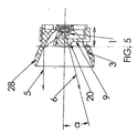
したがって、この発明は、ビームのズームまたは可変焦点式に適用されることが理解できよう。例えば、図2の実施態様において、図5に分かりやすく描写されているように、電動式手段30、31をスパイダ9に結合し、したがって、レンズ2に結合して、レンズ2を反射鏡3の光軸に沿って縦方向に移動してズームを行ったり、生成されるビームの発散や収束を加減したりする。図7は、モータ30を歯車列31に結合して、ズーム制御のための原動力を提供するものを示す。手段30および31は、現在知られまたは今後案出される如何なるタイプの原動機構にしてもよく、例えば、回転可能なリング(図示せず)上に設けた複数の傾斜カムまたは傾斜路を備えて構成してもよく、そのカムは、一つの向きに回転させたとき、ばねで付勢されたスパイダ8を縦軸に沿って前向きに駆り立て、そして、リングを反対の向きに回転させたとき、ばねで付勢されたスパイダ8を縦軸に沿ってばね(図示せず)によって引き戻させる。リングは、手動で回転させることができるし、または、好ましくは、電気モータもしくはソレノイドで回転させことができる。それは、懐中電灯本体に取り付けられたスイッチ(図示せず)で制御されて、懐中電灯を把持する同じ手でのズーム焦点調節の片手操作を可能にする。手動で制御される手動式または電動式ズームが図解されているが、光学回路または無線周波回路がモータ30に結合されて遠隔操作を可能にした場合も、この発明の範囲に含まれる。
Thus, it will be appreciated that the present invention applies to beam zoom or variable focus. For example, in the embodiment of FIG. 2, the motorized means 30, 31 are coupled to the
ズーム焦点調節の可変は、レンズ2、反射鏡3および/またはLED光源1のいずれかの組合せでの相対的な動きによって実現可能である。ここでは、レンズ2および反射鏡3を一つのユニットとして、固定のLED光源1に対して縦方向に変位させることができる。または、その逆に、つまりレンズ2および反射鏡3を一つのユニットとして固定して、LED光源1を移動させる。同様に、上述したように一つのユニットとした固定されたLED光源1および反射鏡3に対して、レンズ2を縦方向に変位させることもできる。または、その逆に、つまりレンズ2を固定しておいて、LED光源1および反射鏡3を一つのユニットとして移動させる。さらにまた、レンズ2、反射鏡3およびLED光源1の移動を各々段階的にかつ独立して行わせることができる場合も、この発明の範囲に入る。そのようなこれら要素の相対的移動を可能とし、この発明の趣旨内で動かすための原動力を提供する手段は、従来の設計原理を応用することによって得られる。
The zoom focus adjustment can be changed by a relative movement in any combination of the
光線5は、反射鏡3から反射されてレンズ2には当たらない光線と定義される。図5の広角ビームの場合、光線5は、図6の狭角ビーム配置構成の場合の光線29が取る第一の位置に示されている。図6では、光線5は、半径方向外側へ移動する。これにより、エネルギは、図6のビームの反射され平行化された狭い部分から取り出されて、図5の広角ビーム配置構成におけるビームの発散する屈折された部分へ入れられる。この手段によって、広角ビームの強度は、それぞれ図6と図5との間の狭角ビーム配置構成から広角ビーム配置構成へとズーム移行する間にエネルギシフトが発生しない場合に比べて、より一層均一に保たれる。
The
図4は、この発明のさらなる実施態様の斜視図である。LED光源18および第二レンズ10は、図3の側面断面図に分かりやすく示された凹面反射鏡17の内部に位置している。図3の実施態様では、レンズ10は、LED光源18自体とは別の素子である。図3の実施態様では、レンズ10は、LED光源18のパッケージの前面に合致する背面23を有するとして示されている。レンズ10の前面は、複合曲面となっていて、表面27が発光体12を概ね中心とした第一の曲率半径r1 を有する球面の周辺リングまたは方位角リングと、第二の小さい曲率半径r2 の面を有し表面27から突き出た中央半球面部25とで構成されている。ここに、r2 <r1 である。レンズ10は、これに代わって、LED光源18のパッケージのレンズとして内蔵させることもできる。
FIG. 4 is a perspective view of a further embodiment of the present invention. The
LEDチップによって吸収されないLED発光体12から放射された光エネルギの本質的に全部が、図3の光線図において光線11、16または14で代表されている。光線16で代表されるLED発光体12から放射する光エネルギは、LED光源18の中心軸または光軸からおおよそ45°離れて、すなわち、前方πステラジアンの立体角内に示されている。光線14は、光線16によって区画された前方πステラジアンの立体角の外側に、中心軸または光軸から90°を超えて離れて、すなわち、前方2πステラジアンの立体角の外側に放射する複数の光線を代表している。中を光線14が通過するレンズ10の部分は、如何なる有意な程度にも光線14の方向に影響を与えたり屈折させたりしないように、LED発光体12を中心として本質的に球形である。光線15は、反射鏡17から反射された複数の光線を代表している。光線11は、LED光源18の中心光軸から光線16までの間のLED発光体12を中心とする円錐体の中、すなわち、前方πステラジアンの立体角の中に存在する複数の光線を代表している。光線13は、レンズ10の表面25により屈折させられた複数の光線を代表している。中を光線13が通過するレンズ10の部分25は、光線13の方向を屈折させまたは変更する。図3に示す光線16および図2に示す光線4は、それぞれ光源18または光源1から直接放射されるように図示されているが、実際には、光線4および光線16は、それぞれ反射されて光線5および光線15となるか、または、屈折させられてそれぞれ光線6および光線13となるかのいずれかになるように、幾何学的構造が選択されている。
Essentially all of the light energy emitted from the
この発明は、LED光源1または18から照明のために放射された光エネルギをほぼ完全な、すなわち、100%の集光効率を提供し、集光したエネルギの制御された画定可能なビームパターンへの分配を提供する。LEDは、チップまたは基板の表面上に実装された発光領域である点に留意されたい。発光接合からの光は、主にチップの表面から前方へ向けられ、極僅かな量がチップの横方向および基板面より僅かに下方へ向けられる。接合から基板の中へ放射した光は、一部は反射され、一部は屈折され、一部は熱として吸収される。この発明は、LED光源1または18から放射された光すなわちエネルギで、それが取り付いている基板に吸収されないものをほぼ全部集光し、そして以下に述べるように、二つの別個の光ビームに向け直す。設計により、これらのビームは、主に単一の方向へ向けることができるが、異なる分布が望まれる用途においては、この限りではない。
The present invention provides light energy emitted for illumination from the LED
この発明は、二つの領域または二つのビームにおけるLEDエネルギの全部を集める。第一の領域は、おおよそ前方2πステラジアンの立体角(側面断面図における45°半角)であり、第二の領域は、例えば、おおよそ前方1.04πステラジアンと2.12πステラジアンの間の立体角(それぞれ、側面断面図における47°半角と95°半角の間)にLED光源1または18から放射されたエネルギである。二つのビームの間の正確な角度分割線は、当面の用途によって変わる。このように、この発明は、LED光源1または18から放射するエネルギのほぼ全部を、表面の僅かの形状損失および半球形ボールレンズ2のための懸架手段9による損失のみで、制御する。形状損失(figure losses)は、光学系のある観点での不完全さによる光損失であり、これには、光路中の継ぎ目(seams)、辺縁(edges)、平縁(fillets)その他の機械的欠陥(disruptions)が数学的な鋭さで完璧に定義されないで、波長程度またはそれより大きい顕微鏡的凹凸または物理的公差を有する三次元物質から出来ているという事実から生じる不完全さによる光損失がある。無限に鋭くはないフレネルレンズの辺縁、すなわち、光の波長より大きい規模で少なくとも部分的に鋭さの欠損を少なくとも有するフレネルレンズの辺縁に起因する損失が、そのような形状損失の一例である。
The present invention collects all of the LED energy in two regions or two beams. The first region is approximately a solid angle of 2π steradians forward (45 ° half angle in the side cross-sectional view), and the second region is, for example, a solid angle approximately between 1.04π steradians forward and 2.12π steradians ( The energy emitted from the LED
例えば、図1および図2の実施態様では、第一の領域のエネルギは、LED1の上方に懸架されたレンズ2を介して集められる。第二の領域のエネルギは、反射鏡3を介して集められる。集光角が僅かに重なっているのは、LED発光体が点光源より大きことにより、発光体からのエネルギが2つの領域の間から漏れ出ないようにするためである。主要素子であるレンズ2および反射鏡3のいずれか一方または両方を変更することによって、システムの諸要件を満たすように最終ビームを設計することができる。この発明によれば、表面20および22のいずれかを変更して最終ビームを制御することができる。
For example, in the embodiment of FIGS. 1 and 2, the energy in the first region is collected via a
反射鏡3は、平行進行するビーム、収束するビーム、または発散するビームを提供するように設計することができる。反射鏡3は、一般的な円錐形をしていてもよいし、していなくてもよく、また、所望のビームパターンを提供するように、切子面が刻まれたり小さな窪みが作られたり、その他の変更を加えてもよい。採用随意であるが、該デバイス24は、反射鏡3およびレンズ2から放射する光をさらに制御しまたは変更する少なくとも一つの追加のレンズおよび/またはLEDパッケージの一部としての追加の表面を有していてもよい。
The
したがって、発光体12に対する縦方向の位置決めを含むレンズ2および10の光学的設計は、この発明の目的を達成するために、この発明の教示に従って変更することが可能であることが理解できるであろう。例えば、二つの部分から成るビームの中央部立体角内における照明の特性を、レンズ2および10の光学的設計、例えば平行光線化の程度によって操作することができる。さらに、ビームの二つの部分、すなわちビームの中央部立体角と周辺部立体角の間の区分線および遷移部は、発光体12に対するレンズ2およびレンズ10の縦方向位置および半径の大きさ、つまり広がりによって操作することができる。
Accordingly, it can be appreciated that the optical design of
多数のデバイス24を配列したアレイを複数設けて追加の機能性を持たせてもよい。これらの配列には、この発明を二つ以上の実現形態で含ませて、個々にレンズ2および反射鏡3の各独特な組を備えることにより最適化することもできる。例えば、上述したデバイスのアレイを使用すれば、単一のセルまたはユニットよりも多くの光を提供することができる。そのようなアレイにおけるこの発明に従った種々の光源を、選択された方向に向けることができ、それは、当面の照明用途に応じた各光学素子それぞれの設計によって異なる。それらの素子は、個々にフォーカスまたはビームパターンを異ならせてもよいし、または、クラスごとに異なるフォーカスまたはビームパターンを有する少なくとも二以上のクラスの素子で構成してもよい。例えば、この発明を街灯に適用した場合、街灯をアレイ状に設計して、ランプアレイの直下には広がったビームを投射し、照明パターンの周縁へはより絞ったまたはより特定にフォーカスしたスポットまたはリングで光を投射するようにしてもよい。
A plurality of arrays in which a large number of devices 24 are arranged may be provided to provide additional functionality. These arrangements can also be optimized by including the invention in two or more implementations and providing each unique pair of
多くの変更や修正が、この発明の精神および範囲から逸脱することなしに、当業者によってなし得るであろう。例えば、具体的に詳解したこの発明の実施態様は、携帯型の懐中電灯について説明してきたが、潜在的な応用範囲はもっと広く、具体的には、ヘッドライト、バイク灯、戦術用閃光灯、医科用ヘッドライト、車両用前照灯または尾灯、オートバイ用照明、飛行機用照明、海上および潜水船舶用照明、非携帯型ランプなど、これらに限定されないが、LED光源が望まれる他のいかなる用途にも応用できる、と理解されなければならない。 Many alterations and modifications may be made by those skilled in the art without departing from the spirit and scope of the invention. For example, the embodiments of the present invention that have been specifically described have been described for portable flashlights, but the potential application range is broader, specifically headlights, bike lights, tactical flashlights, medical Headlights, vehicle headlights or taillights, motorcycle lighting, airplane lighting, marine and submarine lighting, non-portable lamps, but not limited to any other application where an LED light source is desired It must be understood that it can be applied.
さらに、この発明が懐中電灯として実現された場合、スイッチやフォーカスのオプションや組合せを複数用意することができる。例えば、テールキャップスイッチを、懐中電灯頭部または他の部分をねじることによって手動で操作されるフォーカスやズームの手段と組み合わせてもよい。テールキャップスイッチは、ねじり式オンオフスイッチ、摺動式スイッチ、揺動式スイッチまたは押ボタン式スイッチとして実現することができ、フォーカス用の電子スイッチと組み合わせれることができる。スイッチの性質、形態および位置ならびにその操作制御は、現在知られまたは今後案出されるいかなる形態をも取ることができ、また、手動、電動または自動のフォーカス手段および現在知られまたは今後案出されるいかなる形態をとることもできるフォーカス手段と組み合わせることもできる。 Furthermore, when the present invention is realized as a flashlight, a plurality of switches and focus options and combinations can be prepared. For example, the tail cap switch may be combined with a focus or zoom means that is manually operated by twisting the flashlight head or other parts. The tail cap switch can be realized as a torsion type on / off switch, a sliding type switch, a swing type switch or a push button type switch, and can be combined with an electronic switch for focusing. The nature, form and position of the switch and its operational control can take any form currently known or devised, and any manual, electric or automatic focusing means and any currently known or devised future. It can also be combined with focusing means that can take the form.
したがって、ここに具体的に詳解した実施態様は、単に例示の目的で記載されたものであり、前掲の特許請求の範囲により定義される発明を制限するものと受け取ってはいけないと理解されなければならない。例えば、ある請求項の複数要素が一つの特定の組合せで記載されているという事実に拘わらず、この発明は、より少ない要素、より多い要素、または異なる要素での他の組合せをも、たとえそのような組合せが当初請求されていなくても、ここに開示されているものは含むものであると、正に理解しなければならない。 Accordingly, it should be understood that the embodiments specifically described herein are set forth for purposes of illustration only and should not be taken as limiting the invention as defined by the appended claims. Don't be. For example, despite the fact that multiple elements of a claim are described in one particular combination, the invention may include fewer elements, more elements, or other combinations of different elements It should be understood that such combinations are intended to be included, even if such combinations are not initially claimed.
この発明およびその各種実施態様を記述するためにこの明細書で使用された用語は、その一般的に定義された意味においてだけでなく、この明細書における特別の定義により、その一般的に定義されている意味の範囲を超えた構造、材料または働きを含むと理解すべきである。したがって、一つの要素がこの明細書の文脈の中で二つ以上の意味を包含すると理解できる場合には、特許請求の範囲でのその使用は、この明細書およびその用語自体により裏付けられる全ての可能な意味について包括的であると理解しなければならない。 The terms used in this specification to describe the invention and its various embodiments are defined not only in their generally defined meaning, but also by their special definitions in this specification. It should be understood to include structures, materials or functions beyond the meaning of the meaning. Thus, if an element can be understood to encompass more than one meaning within the context of this specification, its use in the claims is intended to be supported by this specification and the term itself. It must be understood that the possible meanings are comprehensive.
したがって、前掲の特許請求の範囲の用語および要素の定義は、この明細書において、文言どおりに記載された要素の組合せだけでなく、実質的に同一の要領で実質的に同一の作用をして実質的に同一の結果を得る全ての等価な(=均等な)構造、材料または働きを包含するものとして、定義されている。したがって、この意味で、前掲の特許請求の範囲におけるどの一つの要素を二つ以上の要素で等価的に(=均等的に)置換してもよいこと、または、特許請求の範囲における二つ以上の要素を単一の要素で置き換えてもよいことを、筆者は意図している。複数の要素が特定の組合せで働くように上述され、そのように当初請求されているかも知れないが、請求された組合せからの一つまたは複数の要素は、場合によっては、その組合せから外すことができ、また請求項された組合せは部分的組合せにまたは部分的組合せの変形に向けられてもよいことを、篤と理解されたい。 Accordingly, the definitions of terms and elements in the appended claims are not limited to the combinations of elements described literally in this specification, but have substantially the same action in substantially the same manner. It is defined as encompassing all equivalent (= equivalent) structures, materials, or functions that achieve substantially the same result. Therefore, in this sense, any one element in the appended claims may be replaced equivalently (= equally) by two or more elements, or two or more in the claims The author intends that one element may be replaced with a single element. Although multiple elements may have been described above and may be originally claimed to work in a particular combination, one or more elements from the claimed combination may be excluded from the combination in some cases. It should be understood that the claimed combinations may be directed to partial combinations or variations of partial combinations.
当業者から見て、請求された主題からの非実質的な変更は、現在知られているものでも今後案出されるものでも、特許請求の範囲の等価物(=均等物)であると意識的に意図している。したがって、当業者にとって現在知られており今後知られる自明な置換は、定義された要素の範囲内であるものと定義されている。 Those skilled in the art are aware that non-substantial changes from the claimed subject matter, whether currently known or devised in the future, are equivalent (= equivalent) to the claims. Is intended. Accordingly, obvious substitutions now known to those skilled in the art and known in the future are defined to be within the scope of the defined elements.
したがって、特許請求の範囲は、上記に具体的に図解および記述されたもの、概念的に等価な(=均等な)もの、自明に置き換えできるもの、およびこの発明の必須の思想を本質的に取り込んでいるものを包含していると理解されるべきである。 Accordingly, the claims essentially incorporate what is specifically illustrated and described above, what is conceptually equivalent (= equivalent), what can be trivially replaced, and essential ideas of the invention. It should be understood as including
1 … 光源
2 … レンズ
3 … 反射鏡
1 ...
Claims (1)
反射鏡によって画定され光軸まわりに定義される周辺部前方立体角内に前記光源から放射された前記光源からの光を反射する位置に置かれた当該反射鏡と、
第1レンズによって画定される中央部前方立体角内に前記光源から放射された光を所定のパターンに集光するように前記光源の縦方向前方に配置された当該第1レンズと
を備えてなり、
それにより、中央部前方立体角内および周辺部前方立体角内に放射された光で構成された複合光ビームを投射する
ことを特徴とする装置。 A light source;
The reflecting mirror placed at a position that reflects light from the light source emitted from the light source within a solid front solid angle defined by the reflecting mirror and defined around the optical axis;
A first lens disposed in front of the light source so as to condense the light emitted from the light source into a predetermined pattern within a solid front solid angle defined by the first lens. ,
Thereby, an apparatus for projecting a composite light beam composed of light emitted in the central forward solid angle and in the peripheral forward solid angle.
Applications Claiming Priority (2)
| Application Number | Priority Date | Filing Date | Title |
|---|---|---|---|
| US50899603P | 2003-10-06 | 2003-10-06 | |
| PCT/US2004/023804 WO2005041254A2 (en) | 2003-10-06 | 2004-07-21 | Improved light source using light emitting diodes and an improved method of collecting the energy radiating from them |
Related Child Applications (1)
| Application Number | Title | Priority Date | Filing Date |
|---|---|---|---|
| JP2010108536A Division JP2010171024A (en) | 2003-10-06 | 2010-05-10 | Apparatus and method for light collection, distribution and zoom |
Publications (2)
| Publication Number | Publication Date |
|---|---|
| JP2007507846A true JP2007507846A (en) | 2007-03-29 |
| JP2007507846A5 JP2007507846A5 (en) | 2008-07-31 |
Family
ID=34520005
Family Applications (2)
| Application Number | Title | Priority Date | Filing Date |
|---|---|---|---|
| JP2006533833A Pending JP2007507846A (en) | 2003-10-06 | 2004-07-21 | Improved light source using light emitting diodes and improved method of collecting energy emitted from light emitting diodes |
| JP2010108536A Withdrawn JP2010171024A (en) | 2003-10-06 | 2010-05-10 | Apparatus and method for light collection, distribution and zoom |
Family Applications After (1)
| Application Number | Title | Priority Date | Filing Date |
|---|---|---|---|
| JP2010108536A Withdrawn JP2010171024A (en) | 2003-10-06 | 2010-05-10 | Apparatus and method for light collection, distribution and zoom |
Country Status (7)
| Country | Link |
|---|---|
| US (2) | US6986593B2 (en) |
| EP (1) | EP1673573A4 (en) |
| JP (2) | JP2007507846A (en) |
| CN (1) | CN1864027B (en) |
| AU (1) | AU2004284713B2 (en) |
| CA (1) | CA2539968C (en) |
| WO (1) | WO2005041254A2 (en) |
Cited By (3)
| Publication number | Priority date | Publication date | Assignee | Title |
|---|---|---|---|---|
| KR101479768B1 (en) * | 2013-10-01 | 2015-01-26 | 한국해양대학교 산학협력단 | LED Searchlight for ships with efficient concentrate light structure |
| KR20170027034A (en) * | 2015-09-01 | 2017-03-09 | 엘지이노텍 주식회사 | An illumination appratus |
| KR20170027035A (en) * | 2015-09-01 | 2017-03-09 | 엘지이노텍 주식회사 | An illumination appratus |
Families Citing this family (133)
| Publication number | Priority date | Publication date | Assignee | Title |
|---|---|---|---|---|
| JP2005243973A (en) * | 2004-02-26 | 2005-09-08 | Kyocera Corp | Light-emitting device and luminaire |
| US7775679B2 (en) * | 2004-08-18 | 2010-08-17 | Advanced Illumination, Inc. | High intensity light source for a machine vision system and method of making same |
| US7543941B2 (en) * | 2004-12-23 | 2009-06-09 | Cooper Technologies Company | Light zoom source using light emitting diodes and an improved method of collecting the energy radiating from them |
| MX2007007939A (en) | 2004-12-27 | 2007-11-07 | Quantum Paper Inc | Addressable and printable emissive display. |
| US7465075B2 (en) * | 2005-03-21 | 2008-12-16 | Visteon Global Technologies, Inc. | Lens assembly for an automobile light assembly having LED light source |
| KR101109592B1 (en) * | 2005-04-25 | 2012-01-31 | 삼성전자주식회사 | Light source module and image projection apparatus employing the same |
| EP1886358A1 (en) * | 2005-05-20 | 2008-02-13 | Datasensor S.p.A. | Lighting fixture for projecting a light beam at a variable projection angle, and relative operating method |
| CN101365909A (en) * | 2005-12-14 | 2009-02-11 | 罗格朗澳大利亚有限公司 | Light source |
| KR20080106402A (en) | 2006-01-05 | 2008-12-05 | 일루미텍스, 인크. | Separate optical device for directing light from an led |
| CA2641832C (en) * | 2006-02-27 | 2012-10-23 | Illumination Management Solutions Inc. | An improved led device for wide beam generation |
| AU2011254053B2 (en) * | 2006-02-27 | 2012-10-11 | Signify Holding B.V. | An improved LED device for wide beam generation |
| US8434912B2 (en) | 2006-02-27 | 2013-05-07 | Illumination Management Solutions, Inc. | LED device for wide beam generation |
| EP3540794B1 (en) * | 2006-03-10 | 2022-03-30 | Nichia Corporation | Light-emitting device |
| JP5586119B2 (en) * | 2006-03-28 | 2014-09-10 | 日亜化学工業株式会社 | Optical component and illumination device using the same |
| US20070264019A1 (en) * | 2006-04-28 | 2007-11-15 | Keng-Hao Nien | Remote controller with narrowed acting angle |
| US20090275157A1 (en) * | 2006-10-02 | 2009-11-05 | Illumitex, Inc. | Optical device shaping |
| EP2070123A2 (en) | 2006-10-02 | 2009-06-17 | Illumitex, Inc. | Led system and method |
| US7731401B2 (en) * | 2006-10-24 | 2010-06-08 | Valeo Sylvania Llc. | High efficiency automotive LED optical system |
| KR100883075B1 (en) * | 2007-03-02 | 2009-02-10 | 엘지전자 주식회사 | Light Emitting Device |
| CN103822172B (en) * | 2007-04-05 | 2017-07-28 | 飞利浦灯具控股公司 | Light-beam shaper |
| US8092042B2 (en) * | 2007-05-03 | 2012-01-10 | Ruud Lighting, Inc. | Shield member in LED apparatus |
| KR101289069B1 (en) * | 2007-05-09 | 2013-07-22 | 엘지디스플레이 주식회사 | Light emitting diode package having structure of dual lens and liquid crystal display device thereby |
| US8430538B2 (en) | 2007-05-21 | 2013-04-30 | Illumination Management Solutions, Inc. | LED device for wide beam generation and method of making the same |
| US8852467B2 (en) | 2007-05-31 | 2014-10-07 | Nthdegree Technologies Worldwide Inc | Method of manufacturing a printable composition of a liquid or gel suspension of diodes |
| US8415879B2 (en) | 2007-05-31 | 2013-04-09 | Nthdegree Technologies Worldwide Inc | Diode for a printable composition |
| US8674593B2 (en) | 2007-05-31 | 2014-03-18 | Nthdegree Technologies Worldwide Inc | Diode for a printable composition |
| US8133768B2 (en) * | 2007-05-31 | 2012-03-13 | Nthdegree Technologies Worldwide Inc | Method of manufacturing a light emitting, photovoltaic or other electronic apparatus and system |
| US8889216B2 (en) | 2007-05-31 | 2014-11-18 | Nthdegree Technologies Worldwide Inc | Method of manufacturing addressable and static electronic displays |
| US9018833B2 (en) | 2007-05-31 | 2015-04-28 | Nthdegree Technologies Worldwide Inc | Apparatus with light emitting or absorbing diodes |
| US9534772B2 (en) | 2007-05-31 | 2017-01-03 | Nthdegree Technologies Worldwide Inc | Apparatus with light emitting diodes |
| US9425357B2 (en) | 2007-05-31 | 2016-08-23 | Nthdegree Technologies Worldwide Inc. | Diode for a printable composition |
| US9343593B2 (en) | 2007-05-31 | 2016-05-17 | Nthdegree Technologies Worldwide Inc | Printable composition of a liquid or gel suspension of diodes |
| US8809126B2 (en) | 2007-05-31 | 2014-08-19 | Nthdegree Technologies Worldwide Inc | Printable composition of a liquid or gel suspension of diodes |
| US8846457B2 (en) | 2007-05-31 | 2014-09-30 | Nthdegree Technologies Worldwide Inc | Printable composition of a liquid or gel suspension of diodes |
| US9419179B2 (en) | 2007-05-31 | 2016-08-16 | Nthdegree Technologies Worldwide Inc | Diode for a printable composition |
| US8877101B2 (en) | 2007-05-31 | 2014-11-04 | Nthdegree Technologies Worldwide Inc | Method of manufacturing a light emitting, power generating or other electronic apparatus |
| US8456392B2 (en) | 2007-05-31 | 2013-06-04 | Nthdegree Technologies Worldwide Inc | Method of manufacturing a light emitting, photovoltaic or other electronic apparatus and system |
| US7686486B2 (en) * | 2007-06-30 | 2010-03-30 | Osram Sylvania Inc. | LED lamp module |
| US7914169B2 (en) * | 2007-10-03 | 2011-03-29 | The Gillette Company | Light-emitting product |
| US7950821B1 (en) | 2007-10-26 | 2011-05-31 | Georgitsis Anthony C | Auxiliary lighting systems |
| JP4277926B1 (en) * | 2007-11-27 | 2009-06-10 | トヨタ自動車株式会社 | Growth method of silicon carbide single crystal |
| US8322881B1 (en) | 2007-12-21 | 2012-12-04 | Appalachian Lighting Systems, Inc. | Lighting fixture |
| US20090184646A1 (en) * | 2007-12-21 | 2009-07-23 | John Devaney | Light emitting diode cap lamp |
| EP2240968A1 (en) | 2008-02-08 | 2010-10-20 | Illumitex, Inc. | System and method for emitter layer shaping |
| DE102008016496A1 (en) * | 2008-03-31 | 2009-10-01 | Zumtobel Lighting Gmbh | Luminaire with punctiform light source and asymmetrical light emission characteristic |
| US7972036B1 (en) | 2008-04-30 | 2011-07-05 | Genlyte Thomas Group Llc | Modular bollard luminaire louver |
| US7985004B1 (en) | 2008-04-30 | 2011-07-26 | Genlyte Thomas Group Llc | Luminaire |
| US7992332B2 (en) | 2008-05-13 | 2011-08-09 | Nthdegree Technologies Worldwide Inc. | Apparatuses for providing power for illumination of a display object |
| US8127477B2 (en) | 2008-05-13 | 2012-03-06 | Nthdegree Technologies Worldwide Inc | Illuminating display systems |
| US8348475B2 (en) * | 2008-05-23 | 2013-01-08 | Ruud Lighting, Inc. | Lens with controlled backlight management |
| US9423096B2 (en) | 2008-05-23 | 2016-08-23 | Cree, Inc. | LED lighting apparatus |
| US8388193B2 (en) * | 2008-05-23 | 2013-03-05 | Ruud Lighting, Inc. | Lens with TIR for off-axial light distribution |
| US8567994B2 (en) * | 2008-05-29 | 2013-10-29 | Sung Hyun High-Tech Co., Ltd. | Street lamp using LEDs |
| US7766509B1 (en) | 2008-06-13 | 2010-08-03 | Lumec Inc. | Orientable lens for an LED fixture |
| US8002435B2 (en) * | 2008-06-13 | 2011-08-23 | Philips Electronics Ltd Philips Electronique Ltee | Orientable lens for an LED fixture |
| CN201225583Y (en) * | 2008-07-01 | 2009-04-22 | 王瑞德 | General-purpose LED lamp installation apparatus |
| US7841750B2 (en) | 2008-08-01 | 2010-11-30 | Ruud Lighting, Inc. | Light-directing lensing member with improved angled light distribution |
| US7854536B2 (en) * | 2008-08-14 | 2010-12-21 | Cooper Technologies Company | LED devices for offset wide beam generation |
| WO2010021676A1 (en) * | 2008-08-18 | 2010-02-25 | Superbulbs, Inc. | Anti-reflective coatings for light bulbs |
| US7934851B1 (en) | 2008-08-19 | 2011-05-03 | Koninklijke Philips Electronics N.V. | Vertical luminaire |
| US8075162B2 (en) * | 2008-09-12 | 2011-12-13 | Light Prescriptions Innovators, Llc | Zoom luminaire with compact non-imaging lens-mirror optics |
| WO2010043069A1 (en) * | 2008-10-15 | 2010-04-22 | 建兴电子科技股份有限公司 | Illumination device and method capable of controlling illumination area |
| WO2010065663A2 (en) | 2008-12-03 | 2010-06-10 | Illumination Management Solutions, Inc. | An led replacement lamp and a method of replacing preexisting luminaires with led lighting assemblies |
| TW201034256A (en) | 2008-12-11 | 2010-09-16 | Illumitex Inc | Systems and methods for packaging light-emitting diode devices |
| US8070328B1 (en) | 2009-01-13 | 2011-12-06 | Koninkliljke Philips Electronics N.V. | LED downlight |
| WO2010084546A1 (en) * | 2009-01-20 | 2010-07-29 | パナソニック株式会社 | Illuminating apparatus |
| US20100182786A1 (en) * | 2009-01-21 | 2010-07-22 | Visionaire Lighting Llc | Hybrid hid/led reflector |
| US8246212B2 (en) * | 2009-01-30 | 2012-08-21 | Koninklijke Philips Electronics N.V. | LED optical assembly |
| CN201434229Y (en) * | 2009-04-11 | 2010-03-31 | 中山泰腾灯饰有限公司 | Spotlight LED lamp |
| US7959322B2 (en) * | 2009-04-24 | 2011-06-14 | Whelen Engineering Company, Inc. | Optical system for LED array |
| US9255686B2 (en) | 2009-05-29 | 2016-02-09 | Cree, Inc. | Multi-lens LED-array optic system |
| US8585253B2 (en) | 2009-08-20 | 2013-11-19 | Illumitex, Inc. | System and method for color mixing lens array |
| US8449128B2 (en) | 2009-08-20 | 2013-05-28 | Illumitex, Inc. | System and method for a lens and phosphor layer |
| TWI528604B (en) * | 2009-09-15 | 2016-04-01 | 無限科技全球公司 | Light emitting, photovoltaic or other electronic apparatus and system |
| US8310158B2 (en) * | 2009-09-23 | 2012-11-13 | Ecofit Lighting, LLC | LED light engine apparatus |
| DE102009047788A1 (en) * | 2009-09-30 | 2011-03-31 | Osram Opto Semiconductors Gmbh | Lighting device for a camera and method for operating the same |
| US8545049B2 (en) | 2009-11-25 | 2013-10-01 | Cooper Technologies Company | Systems, methods, and devices for sealing LED light sources in a light module |
| CN102102849A (en) * | 2009-12-16 | 2011-06-22 | 富准精密工业(深圳)有限公司 | Lens and light-emitting diode module using same |
| CN101839450B (en) * | 2010-01-13 | 2013-10-09 | 海洋王照明科技股份有限公司 | Focusing device of lamp fitting and variable-focus illumination lamp fitting thereof |
| US20120019370A1 (en) * | 2010-01-19 | 2012-01-26 | Mironichev Sergei Y | Devices and methods for providing wireless command and control to electronic devices |
| IT1399369B1 (en) * | 2010-04-09 | 2013-04-16 | Khatod Optoelectronic Srl | PARABOLIC REFLECTOR AND RELATIVE LED LIGHTING DEVICE |
| IT1400106B1 (en) * | 2010-05-20 | 2013-05-17 | Aldabra S R L | LAMP FOR INTERIORS OR EXTERIORS |
| CN201819153U (en) * | 2010-07-27 | 2011-05-04 | 叶秀敏 | Multifunctional optical set |
| US8388198B2 (en) | 2010-09-01 | 2013-03-05 | Illumination Management Solutions, Inc. | Device and apparatus for efficient collection and re-direction of emitted radiation |
| TW201229431A (en) * | 2010-09-24 | 2012-07-16 | Illumitex Inc | High NA optical system and device |
| US8303130B2 (en) | 2010-10-05 | 2012-11-06 | Cooper Technologies Company | Modular optical system for use with light emitting diodes in at least a wall wash configuration |
| US8444306B2 (en) * | 2010-12-20 | 2013-05-21 | Caterpillar Inc. | Vocational truck headlight assembly |
| US20140140069A1 (en) * | 2011-02-24 | 2014-05-22 | Philip Premysler | Led illumination assemblies including partial lenses and metal reflectors |
| US9140430B2 (en) | 2011-02-28 | 2015-09-22 | Cooper Technologies Company | Method and system for managing light from a light emitting diode |
| AU2012223464B2 (en) | 2011-02-28 | 2015-07-30 | Signify Holding B.V. | Method and system for managing light from a light emitting diode |
| US8585238B2 (en) | 2011-05-13 | 2013-11-19 | Lsi Industries, Inc. | Dual zone lighting apparatus |
| USD657087S1 (en) | 2011-05-13 | 2012-04-03 | Lsi Industries, Inc. | Lighting |
| US8449159B2 (en) | 2011-10-18 | 2013-05-28 | Lawrence M. Rice | Combination optics light emitting diode landing light |
| US9046241B2 (en) | 2011-11-12 | 2015-06-02 | Jingqun Xi | High efficiency directional light source using lens optics |
| US9541258B2 (en) | 2012-02-29 | 2017-01-10 | Cree, Inc. | Lens for wide lateral-angle distribution |
| US10408429B2 (en) | 2012-02-29 | 2019-09-10 | Ideal Industries Lighting Llc | Lens for preferential-side distribution |
| US9541257B2 (en) | 2012-02-29 | 2017-01-10 | Cree, Inc. | Lens for primarily-elongate light distribution |
| DE202012003725U1 (en) * | 2012-03-28 | 2012-06-05 | Iventum Gmbh | lamp |
| USD697664S1 (en) | 2012-05-07 | 2014-01-14 | Cree, Inc. | LED lens |
| US8870416B2 (en) * | 2012-08-19 | 2014-10-28 | Lustrous Technology Ltd. | LED package structure having a light-projecting angle adjusting function |
| US9080739B1 (en) | 2012-09-14 | 2015-07-14 | Cooper Technologies Company | System for producing a slender illumination pattern from a light emitting diode |
| US9200765B1 (en) | 2012-11-20 | 2015-12-01 | Cooper Technologies Company | Method and system for redirecting light emitted from a light emitting diode |
| USD715937S1 (en) | 2013-02-08 | 2014-10-21 | Forward Science, Llc | Oral cancer screening device |
| US10413191B2 (en) * | 2013-02-08 | 2019-09-17 | Forward Science Technologies, LLC | Oral examination |
| KR20140104716A (en) * | 2013-02-21 | 2014-08-29 | 삼성전자주식회사 | Light source module and lighting apparatus having the same |
| WO2014130957A1 (en) * | 2013-02-25 | 2014-08-28 | Rensselaer Polytechnic Institute | Low luminance lighting |
| USD718490S1 (en) | 2013-03-15 | 2014-11-25 | Cree, Inc. | LED lens |
| US9523479B2 (en) | 2014-01-03 | 2016-12-20 | Cree, Inc. | LED lens |
| CN103883990B (en) * | 2014-01-26 | 2016-06-22 | 漳浦桂宏工业有限公司 | A kind of luminous adjusting apparatus |
| US10352529B2 (en) | 2014-04-05 | 2019-07-16 | Whelen Engineering Company, Inc. | Collimating optic for LED illumination assembly having transverse slots on emission surface |
| US9523480B2 (en) | 2014-04-05 | 2016-12-20 | Whelen Engineering Company, Inc. | LED illumination assembly with collimating optic |
| US9488331B2 (en) * | 2014-04-17 | 2016-11-08 | Streamlight, Inc. | Portable light with selectable optical beam forming arrangement |
| EP3146260B1 (en) | 2014-05-19 | 2023-03-29 | Whelen Engineering Company, Inc. | Warning light with tinted lens |
| USD740256S1 (en) * | 2014-07-16 | 2015-10-06 | Bose Corporation | Headset |
| US10139078B2 (en) | 2015-02-19 | 2018-11-27 | Whelen Engineering Company, Inc. | Compact optical assembly for LED light sources |
| US10139073B2 (en) | 2015-07-23 | 2018-11-27 | Quadratec, Inc. | Light emitting diode (LED) light bar |
| USD776314S1 (en) | 2015-08-10 | 2017-01-10 | Engo Industries, LLC | Light bar |
| US10208914B2 (en) | 2015-09-09 | 2019-02-19 | Whelen Engineering Company, Inc. | Reflector with concentric interrupted reflecting surfaces |
| EP3356232B1 (en) | 2015-09-29 | 2022-01-26 | Obelux Oy | Precision approach path indicator with a novel reflector arrangement |
| DE102015013271A1 (en) * | 2015-10-13 | 2017-04-13 | Daimler Ag | Device and method for controlling a headlight |
| US10525872B2 (en) | 2015-11-02 | 2020-01-07 | ZRoadz LED, Inc. | System, method and apparatus for mounting accessories to a vehicle |
| US10260699B2 (en) * | 2016-08-09 | 2019-04-16 | Grote Industries, Llc | Bi-optic headlight assembly and lens of bi-optic headlight assembly |
| WO2018066553A1 (en) * | 2016-10-07 | 2018-04-12 | 株式会社小糸製作所 | Vehicle lamp |
| US10420177B2 (en) | 2016-12-19 | 2019-09-17 | Whelen Engineering Company, Inc. | LED illumination module with fixed optic and variable emission pattern |
| US10468566B2 (en) | 2017-04-10 | 2019-11-05 | Ideal Industries Lighting Llc | Hybrid lens for controlled light distribution |
| KR101770543B1 (en) | 2017-05-16 | 2017-09-05 | 주식회사 레드 | A LED lighting equipment for streetlamp |
| USD841620S1 (en) * | 2017-05-24 | 2019-02-26 | Ming Liu | Gaming headset |
| CN107726096A (en) * | 2017-09-11 | 2018-02-23 | 华南师范大学 | The visible light projection system of remote LED |
| WO2019104259A1 (en) | 2017-11-27 | 2019-05-31 | Glint Photonics, Inc. | Configurable luminaires and components |
| USD879345S1 (en) | 2018-02-01 | 2020-03-24 | E. Mishan & Sons, Inc. | Flashlight |
| DE102019108478A1 (en) * | 2019-04-01 | 2020-10-01 | Automotive Lighting Reutlingen Gmbh | Motor vehicle headlights with adjustable spacing of a sharply imaged light distribution |
| DE102020127476A1 (en) * | 2020-10-19 | 2022-04-21 | Erco Gmbh | building light |
| US11747008B2 (en) * | 2021-03-10 | 2023-09-05 | Bolb Inc. | Deep ultraviolet light source |
Citations (4)
| Publication number | Priority date | Publication date | Assignee | Title |
|---|---|---|---|---|
| JPH023602U (en) * | 1988-06-21 | 1990-01-11 | ||
| JPH0269405U (en) * | 1988-11-16 | 1990-05-25 | ||
| US4959757A (en) * | 1988-05-09 | 1990-09-25 | Ichikoh Industries, Ltd. | Automotive lamp assembly |
| JPH0534601U (en) * | 1991-10-11 | 1993-05-07 | 株式会社小糸製作所 | Main / Sub switching projection headlamp for automobile |
Family Cites Families (57)
| Publication number | Priority date | Publication date | Assignee | Title |
|---|---|---|---|---|
| US826205A (en) * | 1904-11-01 | 1906-07-17 | Samuel Groves Whitehouse | Lens for lamps. |
| US4101957A (en) * | 1976-09-10 | 1978-07-18 | Bansun Chang | Zoom operating light |
| US4151584A (en) * | 1977-03-14 | 1979-04-24 | Electro Controls Inc. | Light-collecting reflector |
| US4392187A (en) * | 1981-03-02 | 1983-07-05 | Vari-Lite, Ltd. | Computer controlled lighting system having automatically variable position, color, intensity and beam divergence |
| US4388673A (en) * | 1981-06-22 | 1983-06-14 | Mag Instrument, Inc. | Variable light beam flashlight and recharging unit |
| US4500947A (en) * | 1982-11-10 | 1985-02-19 | Perko, Inc. | Tri spherical lens assembly |
| JPS60121205U (en) * | 1984-01-24 | 1985-08-15 | 株式会社 津山金属製作所 | lamp body |
| US4530040A (en) | 1984-03-08 | 1985-07-16 | Rayovac Corporation | Optical focusing system |
| FR2582780B1 (en) * | 1985-05-31 | 1988-09-09 | Cameleon | LIGHTING DEVICE, PARTICULARLY ADJUSTABLE SCENIC PROJECTOR ACCORDING TO ALL ITS PARAMETERS |
| US4698730A (en) * | 1986-08-01 | 1987-10-06 | Stanley Electric Co., Ltd. | Light-emitting diode |
| GB2195047B (en) * | 1986-08-13 | 1991-04-17 | Canon Kk | Flash device for camera |
| JPH0320961Y2 (en) * | 1986-12-23 | 1991-05-08 | ||
| JPH01501904A (en) * | 1987-01-19 | 1989-06-29 | ナウチノ―プロイズボドストベンノエ オビエディネニエ ポ アフトエレクトロニケ イ アフトトラクトルノム エレクトロオボルドバニユ | optical signal device |
| US4803605A (en) * | 1987-08-04 | 1989-02-07 | Rayovac Corporation | Flashlight with a backup system |
| JP2517368B2 (en) * | 1988-09-27 | 1996-07-24 | 株式会社小糸製作所 | Vehicle headlight and vehicle headlight device |
| US5072346A (en) * | 1988-11-02 | 1991-12-10 | Harding David K | Light beam amplifier |
| US5128848A (en) * | 1989-03-31 | 1992-07-07 | W.C. Heraeus Gmbh | Operating light |
| JPH076564Y2 (en) * | 1990-04-19 | 1995-02-15 | 株式会社小糸製作所 | Variable light distribution vehicle headlights |
| US5103381A (en) * | 1991-01-09 | 1992-04-07 | Uke Alan K | Lamp reflector system |
| US5282121A (en) * | 1991-04-30 | 1994-01-25 | Vari-Lite, Inc. | High intensity lighting projectors |
| US5249109A (en) * | 1991-08-09 | 1993-09-28 | Intermatic Incorporated | Outdoor variable focus light fixture |
| US5404869A (en) * | 1992-04-16 | 1995-04-11 | Tir Technologies, Inc. | Faceted totally internally reflecting lens with individually curved faces on facets |
| US5268977A (en) * | 1992-07-06 | 1993-12-07 | Miller Jack V | Fiber optic zoom-and-dim pin-spot luminaire |
| JP2842260B2 (en) * | 1994-01-11 | 1998-12-24 | 市光工業株式会社 | Structure to prevent color unevenness of projector type headlamp |
| JP2955199B2 (en) * | 1994-12-29 | 1999-10-04 | 本田技研工業株式会社 | Variable light distribution headlamp device |
| DE19501173A1 (en) * | 1995-01-17 | 1996-07-18 | Bosch Gmbh Robert | Headlights for vehicles |
| US5526246A (en) * | 1995-01-20 | 1996-06-11 | Liou; Ching-Chong | Positioning structure for a pattern of a decorative lamp string |
| US5986779A (en) * | 1995-08-18 | 1999-11-16 | Matsushita Electric Industrial Co., Ltd. | Multiple focus lens, an optical head apparatus and an optical information recording-reproducing apparatus |
| DE69635465T2 (en) * | 1995-09-12 | 2006-08-10 | Denso Corp., Kariya | Discharge lamp device |
| US5630661A (en) * | 1996-02-06 | 1997-05-20 | Fox; Donald P. | Metal arc flashlight |
| JPH09243943A (en) * | 1996-03-13 | 1997-09-19 | Minolta Co Ltd | Laser beam scanning optical device |
| US5897196A (en) * | 1996-03-29 | 1999-04-27 | Osram Sylvania Inc. | Motor vehicle headlamp |
| US5934795A (en) * | 1996-06-19 | 1999-08-10 | Radiant Imaging, Inc. | Lens design for outdoor sign |
| DE19639494A1 (en) * | 1996-09-26 | 1998-04-02 | Hella Kg Hueck & Co | Vehicle headlights |
| US6227685B1 (en) * | 1996-10-11 | 2001-05-08 | Mcdermott Kevin | Electronic wide angle lighting device |
| DE19708109A1 (en) * | 1997-02-28 | 1998-09-03 | Hella Kg Hueck & Co | Headlights for vehicles |
| EP0890785B1 (en) * | 1997-07-10 | 2006-08-30 | Automotive Lighting Reutlingen GmbH | Vehicle headlights |
| US5904417A (en) * | 1997-08-04 | 1999-05-18 | Buhl Electric, Inc. | Light fixture with elliptical reflector and mechanical shutter dimmer |
| FR2772111B1 (en) * | 1997-12-05 | 2000-02-25 | Valeo Vision | PROJECTOR WITH HYPERBOLIC REFLECTOR AND OPTICAL BLOCK COMPRISING SUCH A PROJECTOR |
| US6252338B1 (en) * | 1998-05-21 | 2001-06-26 | General Electric Company | Reflector lamp having a reflecting section with faceted surfaces |
| JP3949300B2 (en) * | 1998-11-20 | 2007-07-25 | 株式会社小糸製作所 | Vehicle headlamp |
| JP4011221B2 (en) * | 1999-01-21 | 2007-11-21 | 株式会社小糸製作所 | Vehicle sign light |
| IT1307677B1 (en) * | 1999-02-08 | 2001-11-14 | Magneti Marelli Spa | MOTOR VEHICLE PROJECTOR |
| US6536899B1 (en) * | 1999-07-14 | 2003-03-25 | Bifocon Optics Gmbh | Multifocal lens exhibiting diffractive and refractive powers |
| JP3908428B2 (en) * | 2000-01-06 | 2007-04-25 | 株式会社小糸製作所 | Vehicle sign light |
| TW512214B (en) * | 2000-01-07 | 2002-12-01 | Koninkl Philips Electronics Nv | Luminaire |
| ATE350739T1 (en) * | 2000-03-06 | 2007-01-15 | Teledyne Lighting & Display | LED LIGHT SOURCE WITH OPTICAL FIELD OF VIEW CONTROL SYSTEM |
| JP3556575B2 (en) * | 2000-06-06 | 2004-08-18 | シャープ株式会社 | Objective lens, optical pickup device having the same, and method of assembling objective lens |
| DE60129987T2 (en) * | 2000-08-11 | 2008-05-15 | The Brinkmann Corp., Dallas | FLASHLIGHT WITH ONE LED |
| US6547423B2 (en) * | 2000-12-22 | 2003-04-15 | Koninklijke Phillips Electronics N.V. | LED collimation optics with improved performance and reduced size |
| EP1219887B1 (en) * | 2000-12-25 | 2006-09-27 | Stanley Electric Co., Ltd. | Vehicle light capable of changing light distribution pattern between low-beam mode and high-beam mode by a movable shade and a reflecting surface |
| US6632004B2 (en) * | 2000-12-27 | 2003-10-14 | Canon Kabushiki Kaisha | Lighting device |
| JP3964149B2 (en) * | 2001-04-10 | 2007-08-22 | 株式会社小糸製作所 | Vehicle headlamp |
| JP3779173B2 (en) * | 2001-04-24 | 2006-05-24 | 株式会社小糸製作所 | Vehicle headlamp |
| US6827467B2 (en) * | 2002-02-18 | 2004-12-07 | Canon Kabushiki Kaisha | Illuminating apparatus |
| US6796690B2 (en) * | 2002-03-14 | 2004-09-28 | The Boeing Company | LED light source |
| ITMI20021625A1 (en) * | 2002-07-23 | 2004-01-23 | Coemar Spa | BRIGHT PROJECTOR WITH MEANS TO PERIMETALLY DELIMIT THE BEAM OF LIGHT EMITTED |
-
2004
- 2004-07-21 AU AU2004284713A patent/AU2004284713B2/en active Active
- 2004-07-21 JP JP2006533833A patent/JP2007507846A/en active Pending
- 2004-07-21 WO PCT/US2004/023804 patent/WO2005041254A2/en active Application Filing
- 2004-07-21 US US10/897,297 patent/US6986593B2/en active Active
- 2004-07-21 CA CA002539968A patent/CA2539968C/en active Active
- 2004-07-21 CN CN2004800292517A patent/CN1864027B/en not_active Ceased
- 2004-07-21 EP EP04779039.9A patent/EP1673573A4/en not_active Withdrawn
-
2005
- 2005-08-29 US US11/215,538 patent/US7114832B2/en active Active
-
2010
- 2010-05-10 JP JP2010108536A patent/JP2010171024A/en not_active Withdrawn
Patent Citations (4)
| Publication number | Priority date | Publication date | Assignee | Title |
|---|---|---|---|---|
| US4959757A (en) * | 1988-05-09 | 1990-09-25 | Ichikoh Industries, Ltd. | Automotive lamp assembly |
| JPH023602U (en) * | 1988-06-21 | 1990-01-11 | ||
| JPH0269405U (en) * | 1988-11-16 | 1990-05-25 | ||
| JPH0534601U (en) * | 1991-10-11 | 1993-05-07 | 株式会社小糸製作所 | Main / Sub switching projection headlamp for automobile |
Cited By (5)
| Publication number | Priority date | Publication date | Assignee | Title |
|---|---|---|---|---|
| KR101479768B1 (en) * | 2013-10-01 | 2015-01-26 | 한국해양대학교 산학협력단 | LED Searchlight for ships with efficient concentrate light structure |
| KR20170027034A (en) * | 2015-09-01 | 2017-03-09 | 엘지이노텍 주식회사 | An illumination appratus |
| KR20170027035A (en) * | 2015-09-01 | 2017-03-09 | 엘지이노텍 주식회사 | An illumination appratus |
| KR102465694B1 (en) * | 2015-09-01 | 2022-11-11 | 쑤저우 레킨 세미컨덕터 컴퍼니 리미티드 | An illumination apparatus |
| KR102471181B1 (en) * | 2015-09-01 | 2022-12-01 | 쑤저우 레킨 세미컨덕터 컴퍼니 리미티드 | An illumination apparatus |
Also Published As
| Publication number | Publication date |
|---|---|
| AU2004284713A1 (en) | 2005-05-06 |
| WO2005041254A2 (en) | 2005-05-06 |
| CA2539968C (en) | 2009-06-02 |
| US20060056188A1 (en) | 2006-03-16 |
| US20050073849A1 (en) | 2005-04-07 |
| EP1673573A4 (en) | 2016-01-13 |
| US7114832B2 (en) | 2006-10-03 |
| WO2005041254A3 (en) | 2005-06-23 |
| CA2539968A1 (en) | 2005-05-06 |
| US6986593B2 (en) | 2006-01-17 |
| AU2004284713B2 (en) | 2007-11-15 |
| CN1864027B (en) | 2010-08-25 |
| CN1864027A (en) | 2006-11-15 |
| JP2010171024A (en) | 2010-08-05 |
| EP1673573A2 (en) | 2006-06-28 |
Similar Documents
| Publication | Publication Date | Title |
|---|---|---|
| JP2007507846A (en) | Improved light source using light emitting diodes and improved method of collecting energy emitted from light emitting diodes | |
| US7543941B2 (en) | Light zoom source using light emitting diodes and an improved method of collecting the energy radiating from them | |
| US9109781B2 (en) | Device and apparatus for efficient collection and re-direction of emitted radiation | |
| JP4954288B2 (en) | Reflective projector | |
| US7748872B2 (en) | Light-conducting pedestal configuration for an LED apparatus which collects almost all and distributes substantially all of the light from the LED | |
| EP1753996B1 (en) | An apparatus and method for improved illumination area fill | |
| JP4537822B2 (en) | Lamp | |
| JP2007507846A5 (en) | ||
| JP2013502679A5 (en) | ||
| US20130077332A1 (en) | Light for an Aircraft | |
| US20040130891A1 (en) | Mobile lamp | |
| CN106051572A (en) | Vehicle lamp | |
| EP2924348B1 (en) | Lighting apparatus | |
| US4039816A (en) | Arrangement for transmitting light energy | |
| US11480314B2 (en) | Light collimation assembly and light emitting devices | |
| JP2004134357A (en) | Indication lamp comprising optical piece for performing indicating function | |
| AU2007219309B2 (en) | Method for shifting energy between beams when focusing or defocusing | |
| JP2010153402A (en) | Lighting fixture | |
| HAN | RELATED APPLICATIONS | |
| JPWO2020161846A1 (en) | Projection device |
Legal Events
| Date | Code | Title | Description |
|---|---|---|---|
| A621 | Written request for application examination |
Free format text: JAPANESE INTERMEDIATE CODE: A621 Effective date: 20070607 |
|
| A521 | Request for written amendment filed |
Free format text: JAPANESE INTERMEDIATE CODE: A523 Effective date: 20080115 |
|
| A521 | Request for written amendment filed |
Free format text: JAPANESE INTERMEDIATE CODE: A523 Effective date: 20080612 |
|
| A131 | Notification of reasons for refusal |
Free format text: JAPANESE INTERMEDIATE CODE: A131 Effective date: 20091110 |
|
| A601 | Written request for extension of time |
Free format text: JAPANESE INTERMEDIATE CODE: A601 Effective date: 20100210 |
|
| A602 | Written permission of extension of time |
Free format text: JAPANESE INTERMEDIATE CODE: A602 Effective date: 20100218 |
|
| A601 | Written request for extension of time |
Free format text: JAPANESE INTERMEDIATE CODE: A601 Effective date: 20100310 |
|
| A602 | Written permission of extension of time |
Free format text: JAPANESE INTERMEDIATE CODE: A602 Effective date: 20100317 |
|
| A601 | Written request for extension of time |
Free format text: JAPANESE INTERMEDIATE CODE: A601 Effective date: 20100412 |
|
| A602 | Written permission of extension of time |
Free format text: JAPANESE INTERMEDIATE CODE: A602 Effective date: 20100419 |
|
| A521 | Request for written amendment filed |
Free format text: JAPANESE INTERMEDIATE CODE: A523 Effective date: 20100510 |
|
| A02 | Decision of refusal |
Free format text: JAPANESE INTERMEDIATE CODE: A02 Effective date: 20101116 |