RU2446373C1 - Cartridge feeder for multicharge small arms - Google Patents
Cartridge feeder for multicharge small arms Download PDFInfo
- Publication number
- RU2446373C1 RU2446373C1 RU2010143259/11A RU2010143259A RU2446373C1 RU 2446373 C1 RU2446373 C1 RU 2446373C1 RU 2010143259/11 A RU2010143259/11 A RU 2010143259/11A RU 2010143259 A RU2010143259 A RU 2010143259A RU 2446373 C1 RU2446373 C1 RU 2446373C1
- Authority
- RU
- Russia
- Prior art keywords
- tray
- trigger
- magazine
- cartridge
- lever
- Prior art date
Links
- 230000000694 effects Effects 0.000 abstract description 2
- 239000000126 substance Substances 0.000 abstract 1
- 230000009471 action Effects 0.000 description 17
- 230000007246 mechanism Effects 0.000 description 9
- 230000000903 blocking effect Effects 0.000 description 2
- 230000003993 interaction Effects 0.000 description 2
- 230000004048 modification Effects 0.000 description 2
- 238000012986 modification Methods 0.000 description 2
- 230000000630 rising effect Effects 0.000 description 2
- 239000002775 capsule Substances 0.000 description 1
- 230000008859 change Effects 0.000 description 1
- 238000000605 extraction Methods 0.000 description 1
- 238000010304 firing Methods 0.000 description 1
- 230000004044 response Effects 0.000 description 1
Images
Landscapes
- Toys (AREA)
Abstract
Description
Область техники, к которой относится изобретениеFIELD OF THE INVENTION
Настоящее изобретение относится к устройству подачи патронов для многозарядного огнестрельного оружия, в частности полуавтоматического или автоматического ружья.The present invention relates to a cartridge feeding device for a multi-shot firearm, in particular a semi-automatic or automatic rifle.
Предшествующий уровень техникиState of the art
Многозарядное огнестрельное оружие, в частности полуавтоматические или автоматические ружья, имеющие газоотводной механизм, или ружья с коротким или длинным ходом ствола, осуществляющие инерционный принцип работы, или ружья с ручным перезаряжанием (помповым действием), оснащается устройством подачи патронов, подающим очередной патрон из магазина оружия на лоток для подачи в патронник, перед нанесением курком удара по ударнику. Поскольку конструкции ружей и их основные составные части известны специалисту, в настоящем описании раскрывается только устройство подачи патронов из магазина в патронник.Multiply charged firearms, in particular semi-automatic or automatic shotguns having a gas vent mechanism, or short or long barrel shotguns that carry out the inertial principle of operation, or hand-reloading guns (pump action), is equipped with a cartridge-feeding device that feeds another cartridge from the weapons store on the tray for feeding into the chamber, before the hammer strikes the hammer. Since the design of the guns and their main components are known to the specialist, in the present description only the device for supplying cartridges from the magazine to the chamber is disclosed.
Устройства подачи известны из уровня техники.Feeders are known in the art.
В документе US 6742298, 01.06.2004 раскрыта блокировка, предназначенная для устройства подачи патронов ружья с подствольным магазином, в котором лоток, который получает из магазина патрон и подает его затем к патроннику, удерживается посредством блокировки, взаимодействующей с курком, в промежуточном положении, в котором невозможна подача патрона из магазина на лоток. При приведении в действие курка происходит снятие блокировки и освобождение лотка для его перемещения в положение, при котором осуществляется подача патрона из магазина на лоток.US Pat. No. 6742298, 06/01/2004, discloses a lock for feeding a cartridge for a shotgun with an under-barrel magazine, in which the tray, which receives a cartridge from the magazine and then delivers it to the chamber, is held in an intermediate position by means of a lock interacting with the trigger in which the cartridge cannot be fed from the magazine onto the tray. When the trigger is activated, the lock is released and the tray is released to move it to the position in which the cartridge is fed from the magazine to the tray.
Также в документе US 4601122, 22.07.1986 раскрыто ружье, имеющее подствольный магазин и устройство подачи патронов, содержащее лоток, который получает от магазина патрон и поставляет его к патроннику; рычаг, который, взаимодействуя с лотком, может изменять свое положение - от положения, в котором этот рычаг препятствует выходу патронов из магазина на лоток, на положение, в котором этот рычаг позволяет выход патрона на лоток, для дальнейшей подачи его в патронник.Also, in document US 4601122, 07/22/1986 a gun is disclosed having an under-barrel magazine and a cartridge feeding device, comprising a tray that receives a cartridge from the magazine and delivers it to the chamber; a lever, which, interacting with the tray, can change its position - from the position in which this lever prevents the cartridges from leaving the magazine on the tray, to the position in which this lever allows the cartridge to exit to the tray, for further feeding it into the chamber.
В современном огнестрельном оружии существует потребность сокращения времени срабатывания ударного механизма и механизма перезарядки, которое в целом желательно свести к минимальному технологически достижимому значению. Вследствие этого, в известных из предшествующего уровня техники конструкциях устройства подачи патронов, часто возникает ситуация, когда лоток, вследствие как собственной инерционности, так и инерционности опускающих его средств, например пружины, не успевает своевременно опуститься в нижнее положение для освобождения патрона в магазине, до момента выстрела.In modern firearms, there is a need to reduce the response time of the striking mechanism and reloading mechanism, which is generally desirable to reduce to the minimum technologically achievable value. As a result of this, in the designs of the cartridge feeding device known from the prior art, a situation often arises when the tray, due to both its own inertia and the inertia of the means lowering it, such as a spring, does not have time to timely lower to the lower position to release the cartridge in the magazine, the moment of the shot.
Особенно часто данная проблема возникает в случае мощных боеприпасов и при высоких скоростях работы затворного механизма оружия.Especially often this problem arises in the case of powerful ammunition and at high speeds of the bolt mechanism of the weapon.
Если лоток не достигает нижнего положения, то следующий патрон не может поступить на лоток, до того, как лоток под действием затвора, начинает подъем. Следовательно, происходит цикл «пустой» перезарядки ружья, которое оказывается с взведенным курком, закрытым затвором и пустым патронником. В результате работа оружия становится нестабильной и ненадежной.If the tray does not reach the bottom position, then the next cartridge cannot enter the tray before the tray begins to rise under the action of the shutter. Consequently, there is a cycle of "empty" reloading of the gun, which is cocked, the bolt closed and the chamber empty. As a result, the operation of the weapon becomes unstable and unreliable.
Сущность изобретенияSUMMARY OF THE INVENTION
Задачей настоящего изобретения является создание усовершенствованного устройства подачи патронов для многозарядного огнестрельного оружия с любым типом перезаряжания, в частности ружья полуавтоматического или автоматического типа с подствольным магазином, которое является надежным в работе и предотвращает возникновение цикла «пустой» перезарядки.An object of the present invention is to provide an improved cartridge feeding device for a multi-shot firearm with any type of reloading, in particular a semi-automatic or automatic type rifle with an under-barrel magazine, which is reliable in operation and prevents the occurrence of an empty reload cycle.
Для обеспечения решения этой задачи в устройстве подачи патронов в настоящем изобретении предусмотрено фиксирование лотка в промежуточном положении, освобождение лотка и его опускание в нижнее положение для освобождения патрона в магазине до воздействия курка на ударник и блокировка лотка в этом нижнем положении до подачи патрона из магазина на лоток.To provide a solution to this problem, the cartridge feeding device of the present invention provides for locking the tray in an intermediate position , releasing the tray and lowering it to a lower position to release the cartridge in the magazine until the hammer impacts the hammer and lock the tray in this lower position until the cartridge is fed from the magazine onto tray.
Согласно настоящему изобретению предлагается устройство подачи патронов для многозарядного огнестрельного оружия с любым типом перезаряжания, в частности ружья полуавтоматического или автоматического типа, включающего в себя ствол, патронник в стволе, затвор для открывания и закрывания патронника, ударник в упомянутом затворе, курок для нанесения удара по ударнику и шептало для удержания курка, спусковой крючок для освобождения курка от шептала, а также магазин для размещения запасных патронов, снабженный средством подачи патронов из магазина, при этом устройство содержит лоток для принятия патронов из магазина и подачи к патроннику, рычаг управления подачей патронов из магазина к лотку, блокировку для удержания лотка в промежуточном положении. Настоящее изобретение характеризуется тем, что курок снабжен средством опускания лотка и средством снятия блокировки лотка, выполненными так, что при перемещении курка в положение удара по ударнику средство снятия блокировки лотка обеспечивает снятие блокировки лотка в промежуточном положении, а средство опускания лотка - принудительное опускание лотка в нижнее положение, при котором патрон освобождается из магазина и поступает на лоток, при этом рычаг управления подачей патронов из магазина к лотку при опускании лотка поворачивается из положения, в котором он препятствует поступлению патронов из магазина, в положение, при котором он блокирует лоток в нижнем положении и позволяет патрону из магазина поступать к лотку.According to the present invention, there is provided a cartridge feeding device for a multiple-charge firearm with any type of reloading, in particular a semi-automatic or automatic type rifle, including a barrel, a chamber in the barrel, a shutter for opening and closing the chamber, a hammer in the said shutter, a trigger for striking a drummer and a sear to hold the trigger, a trigger to release the trigger from the sear, as well as a magazine for placing spare cartridges, equipped with a means for feeding cartridges and store, the apparatus comprises a tray for making rounds from the magazine and feeding to the chamber, flow control lever of cartridges from the magazine to the tray, a lock for retaining the tray in an intermediate position. The present invention is characterized in that the trigger is provided with a means of lowering the tray and means for unlocking the tray, such that when the trigger is moved to the impact position of the hammer, the means for releasing the locking of the tray unlocks the tray in an intermediate position, and the means for lowering the tray force the tray to lower the lower position, in which the cartridge is released from the magazine and enters the tray, while the control lever for feeding cartridges from the magazine to the tray is rotated when lowering the tray from the position in which it prevents the cartridges from entering the magazine, to the position in which it locks the tray in the lower position and allows the cartridge from the magazine to enter the tray.
В одном варианте средство опускания лотка представляет собой выступ, выполненный за одно целое с курком.In one embodiment, the tray lowering means is a protrusion made integrally with the trigger.
Также возможно, что средство опускания лотка представляет собой рычаг, установленный с возможностью поворота на оси курка. Рычаг может быть оснащен средствами для геометрического или кинематического взаимодействия с курком и осуществления совместного поворота.It is also possible that the means for lowering the tray is a lever mounted rotatably on the axis of the trigger. The lever can be equipped with means for geometric or kinematic interaction with the trigger and joint rotation.
Согласно настоящему изобретению может быть предусмотрено, что упомянутый рычаг выполнен с возможностью взаимодействия с боевой пружиной курка для поворота на оси курка и опускания лотка.According to the present invention, it may be provided that said lever is adapted to interact with the trigger spring of the trigger for turning on the axis of the trigger and lowering the tray.
В предпочтительном варианте курок может быть дополнительно оснащен выступом для взаимодействия с упомянутым рычагом и приведения его в первоначальное положение.In a preferred embodiment, the trigger may be further equipped with a protrusion for interacting with said lever and bringing it to its original position.
Согласно настоящему изобретению средство снятия блокировки лотка представляет собой зуб, выполненный за одно целое с курком и взаимодействующий с геометрическим и силовым замыканием с блокировкой лотка. Для осуществления геометрического и силового замыкания блокировка лотка выполнена в форме, соответствующей форме зуба. Поскольку средства для создания геометрического и силового замыкания элементов в целом известны специалисту, в настоящем описании они дополнительно не поясняются.According to the present invention, the means for removing the locking of the tray is a tooth made in one piece with the trigger and interacting with a geometric and power circuit with the locking of the tray. To implement geometric and power closure, the locking of the tray is made in the form corresponding to the shape of the tooth. Since the means for creating a geometric and power circuit of the elements as a whole are known to the skilled person, they are not further explained in the present description.
Альтернативно, средство снятия блокировки лотка может представлять собой зуб, выполненный за одно целое с упомянутым рычагом и взаимодействующий с геометрическим и силовым замыканием с блокировкой лотка.Alternatively, the tool to release the locking of the tray may be a tooth made in one piece with the said lever and interacting with a geometric and power circuit with the locking of the tray.
За счет предлагаемой конструкции устройства подачи патронов для многозарядного огнестрельного оружия полностью устраняется возникновение цикла «пустой» перезарядки ружья, что обеспечивает надежное использование оружия, при этом лоток гарантированно занимает нижнее положение до момента воздействия курка на ударник, таким образом, инерционность деталей механизма подачи не сказывается на надежность работы подающего механизма.Due to the proposed design of the cartridge feeding device for multi-shot firearms, the occurrence of a cycle of “empty” reloading of the gun is completely eliminated, which ensures reliable use of the weapon, while the tray is guaranteed to be in the lowest position until the trigger impacts the hammer, so the inertia of the parts of the feed mechanism does not affect on the reliability of the feed mechanism.
Детали и преимущества настоящего изобретения станут более очевидными из последующего описания изобретения, представленного ниже со ссылкой на прилагаемые чертежи.Details and advantages of the present invention will become more apparent from the following description of the invention presented below with reference to the accompanying drawings.
Представленные примеры являются только иллюстрацией, обеспечивающей понимание принципа настоящего изобретения для специалиста, в рамках которого возможны различные модификации, и они не служат для ограничения объема притязаний, который определяется только формулой настоящего изобретения.The presented examples are only an illustration, providing an understanding of the principle of the present invention for a specialist, in the framework of which various modifications are possible, and they do not serve to limit the scope of claims, which is determined only by the claims of the present invention.
ОПИСАНИЕ ЧЕРТЕЖЕЙDESCRIPTION OF DRAWINGS
Фиг. 1 - продольный разрез секции ружья с взведенным курком, готовым к выстрелу, с патроном в патроннике и с запасными боеприпасами, размещенными в магазине, в одном варианте выполнения средства опускания лотка;FIG. 1 is a longitudinal section of a shotgun section with a cocked trigger ready for firing, with a cartridge in the chamber and with spare ammunition housed in a magazine, in one embodiment of a tray lowering means;
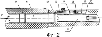
Фиг. 2 - разрез по линии II-II Фиг. 1;FIG. 2 is a section along line II-II of FIG. one;
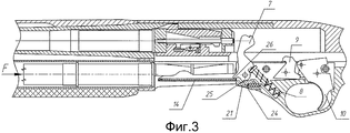
Фиг. 3 - продольный разрез ружья, в котором лоток находится в промежуточном положении;FIG. 3 is a longitudinal section through a gun in which the tray is in an intermediate position;
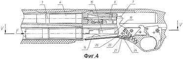
Фиг. 4 - продольный разрез ружья, в котором курок наносит удар по ударнику, а лоток находится в нижнем положении и готов к приему нового патрона из магазина;FIG. 4 - a longitudinal section of the gun, in which the trigger strikes the hammer, and the tray is in the lower position and is ready to receive a new cartridge from the magazine;
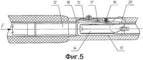
Фиг. 5 - разрез по линии V-V Фиг. 4;FIG. 5 is a section along the line V-V of FIG. four;
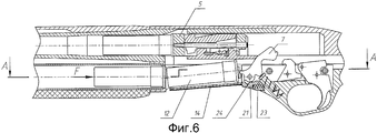
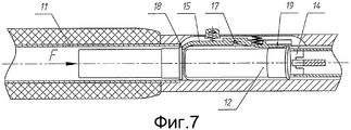
Фиг. 6 - продольный разрез ружья, в котором оружие находится в положении после выстрела, когда новый патрон уже помещен на лоток;FIG. 6 is a longitudinal section of a gun in which the weapon is in position after a shot when a new cartridge is already placed on the tray;
Фиг. 7 - разрез по линии А-А Фиг. 6;FIG. 7 is a section along line AA of FIG. 6;
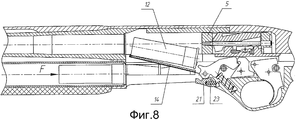
Фиг. 8 - продольный разрез ружья, при этом лоток находится в верхнем положении для подачи патрона в патронник;FIG. 8 is a longitudinal section of the gun, with the tray in the upper position for feeding the cartridge into the chamber;
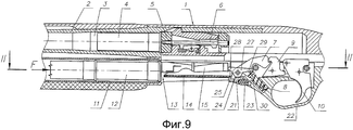
Фиг. 9 - продольный разрез секции ружья с взведенным курком, готовым к выстрелу патроном в патроннике и с запасными боеприпасами, размещенными в магазине, в другом варианте выполнения средства опускания лотка;FIG. 9 is a longitudinal section of a shotgun section with a cocked trigger ready to be fired by a cartridge in the chamber and with spare ammunition housed in a magazine, in another embodiment of the tray lowering means;
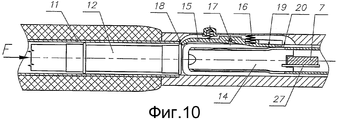
Фиг. 10 - разрез по линии II-II Фиг. 9;FIG. 10 is a section along line II-II of FIG. 9;
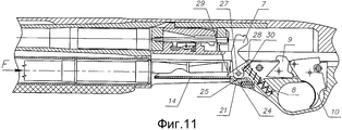
Фиг. 11 - продольный разрез ружья, в котором лоток находится в промежуточном положении во втором варианте выполнения средства опускания лотка;FIG. 11 is a longitudinal section through a shotgun in which the tray is in an intermediate position in a second embodiment of the tray lowering means;
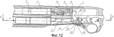
Фиг. 12 - продольный разрез ружья, в котором курок наносит удар по ударнику, а лоток находится в нижнем положении и готов получить новый патрон из магазина;FIG. 12 is a longitudinal section of a gun in which the trigger strikes the hammer, and the tray is in the low position and is ready to receive a new cartridge from the magazine;
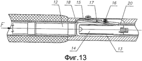
Фиг. 13 - разрез по линии V-V Фиг. 12;FIG. 13 is a section along the line V-V of FIG. 12;
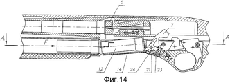
Фиг. 14 - продольный разрез ружья, в котором оружие находится в положении после выстрела, когда новый патрон уже помещен на лоток;FIG. 14 is a longitudinal section through a shotgun in which a weapon is in position after a shot when a new cartridge is already placed on the tray;
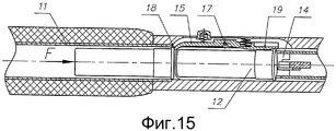
Фиг. 15 - разрез по линии А-А Фиг. 14;FIG. 15 is a section along line AA of FIG. fourteen;
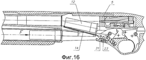
Фиг. 16 - продольный разрез ружья, при этом лоток находится в верхнем положении для подачи патрона в патронник;FIG. 16 is a longitudinal section of a gun, while the tray is in the upper position for feeding the cartridge into the chamber;
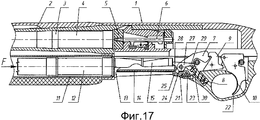
Фиг. 17 - продольный разрез секции ружья с взведенным курком, готовым к выстрелу патроном в патроннике и с запасными боеприпасами, размещенными в магазине, в альтернативном варианте выполнения средства снятия блокировки лотка;FIG. 17 is a longitudinal sectional view of a shotgun section with a cocked trigger ready to be fired by a cartridge in the chamber and with spare ammunition placed in a magazine, in an alternative embodiment of a tray lock release means;
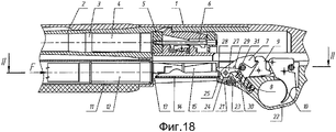
Фиг. 18 - продольный разрез секции ружья с взведенным курком, готовым к выстрелу патроном в патроннике и с запасными боеприпасами, размещенными в магазине, в альтернативном варианте выполнения средства опускания лотка;FIG. 18 is a longitudinal sectional view of a shotgun section with a cocked trigger ready to be fired by a cartridge in the chamber and with spare ammunition placed in a magazine, in an alternative embodiment of a tray lowering means;
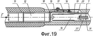
Фиг. 19 - разрез по линии II-II Фиг. 18.FIG. 19 is a section along line II-II of FIG. eighteen.
На сопровождающих фигурах позиции, относящие к одинаковым элементам, имеют общее обозначение.In the accompanying figures, the positions referring to the same elements have a common designation.
Так, на фиг. 1-19 позиция 1 относится в целом к ружью, в частности полуавтоматическому ружью с подствольным магазином. Ружье включает в себя ствол 2 с патронником 3, в котором размещен патрон 4, затвор 5 для открытия и закрытия патронника 3, содержащий размещенный в нем ударник 6, курок 7, приводимый в действие пружиной 8 через толкатель 30 курка и предназначенный для удара по ударнику 6, шептало 9 для удержания курка 7 во взведенном положении и спусковой крючок 10, который управляет шепталом 9 для освобождения курка 7.So in FIG. 1-19,
Под стволом 2 расположен магазин 11 для запасных боеприпасов 12, перемещаемых в направлении стрелки F, например, посредством пружины (не показана), отсек 13 подачи, в котором расположен лоток 14, который служит для получения патрона из магазина и подъема его на линию досылания, когда затвор 5 закончит экстракцию стреляной гильзы патрона 4 и, одновременно, взведет курок 7.Under the
В отсеке 13 подачи, сбоку относительно лотка 14 расположен рычаг 15, который имеет возможность вращения и поперечного перемещения относительно оси 17. Передний конец 18 рычага 15 препятствует движению патрона 12, который находится в магазине, и расположен перед отсеком 13 подачи. Задняя поверхность 19 рычага 15 взаимодействует с поверхностью 20 лотка 14, находящегося в промежуточном положении, при котором патрон 12 не может поступать из магазина 11 на лоток 14. Пружина 16, при опускании лотка 14, служит для перемещения рычага 15 в положение, которое позволяет выход патрона 12 из магазина на лоток 14.In the
Задняя часть лотка 14, взаимодействует с блокировкой 21 так, что последняя не дает лотку опуститься в нижнее положение, когда блокировка 21 находится в переднем положении. Блокировка 21 расположена на основании ударно-спускового механизма 22 и поджата пружиной 23. Эта пружина служит для возврата блокировки 21 в первоначальное положение.The back of the
Как показано, например, на фиг. 1, 9, блокировка 21 имеет зуб 24, который выполнен с возможностью геометрического и силового взаимодействия с зубом 25, расположенным на курке 7. При взаимодействии зубьев 24 и 25 обеспечивается перемещение блокировки 21 в заднее положение и освобождение лотка 14.As shown, for example, in FIG. 1, 9, the
Согласно фиг. 1-8 на курке 7 расположен выступ 26, который при срабатывании курка и снятии блокировки лотка обеспечивает опускание лотка 14 из промежуточного положения в нижнее положение до момента воздействия курка 7 на ударник 6. При этом происходит освобождение патрона в магазине и поступление его на лоток 14.According to FIG. 1-8 on the
Хотя действие ружья само по себе известно и не нуждается в дополнительном пояснении, следует обратить внимание на то, что прежде чем произойдет выстрел патроном 4, курок 7 во взведенном состоянии удерживается шепталом 9, и затвор 5 расположен в крайнем переднем положении, закрывая патронник 3. Такое положение изображено на фиг. 1 и 2. Блокировка 21 в этом случае находится в переднем положении, то есть под лотком 14, удерживая его в промежуточном положении. В этом положении, поверхность 20 лотка расположена на уровне напротив задней поверхности 19 рычага 15, при этом рычаг 15 находится в таком положении, чтобы передний конец 18 рычага препятствовал движению патрона 12 из магазина 11.Although the action of the gun itself is known and does not need additional explanation, you should pay attention to the fact that before the
При нажатии на спусковой крючок 10 происходит расцепление шептала 9 с курком 7 и последний под действием пружины 8 и толкателя начинает вращаться вокруг своей оси для удара по ударнику 6. Однако, прежде чем курок ударит по ударнику, как показано на фиг. 3, зуб 25 курка начинает взаимодействие с зубом 24 блокировки 21 и при дальнейшем вращении курка 7 перемещает блокировку 21 к точке, где блокировка освободит лоток 14, а выступ 26 начнет взаимодействие с лотком.When the
Как показано на фиг.4 и 5, в момент, когда курок 7 нанесет удар по ударнику 6, выступ 26 курка опустит лоток 14 в нижнее положение. В это время, задняя поверхность 19 рычага 15 больше не удерживается поверхностью 20 лотка и рычаг 15 начинает свободно вращаться к внутренней части отсека подачи 13 вокруг оси 17 под действием пружины 16, блокируя задним концом лоток 14 от подъема, передний конец 18 рычага больше не блокирует патрон 12 в магазине, а ударник воспламенит капсюль патрона 4, находящегося в патроннике 3 ствола.As shown in FIGS. 4 and 5, at the moment when the
В момент выстрела под действием автоматики перезаряжания затвор 5 начинает перемещаться в заднее положение, экстрагируя стреляную гильзу, и взводит курок. Курок прекратит воздействие на зуб 24 блокировки 21, и та под действием пружины 23 переместится до соприкосновения с лотком. Патрон 12, под действием пружины, перемещается на лоток 14. По мере выхода из магазина патрон воздействует на заднюю поверхность 19 рычага 15, и тот в свою очередь поворачивается в обратном направлении вокруг оси 17 и передним концом 18 блокирует следующий патрон в магазине, а задний конец освобождает лоток - что изображено на фиг. 6 и 7.At the time of the shot, under the action of automatic reloading, the
Дойдя до заднего положения, затвор 5 под действием возвратного механизма начинает движение в переднее положение, поднимает лоток 14 с находящимся на нем патроном 12 на линию досылания. При этом блокировка 21 под действием пружины 23 занимает переднее положение. Такое положение изображено на фиг. 8.Having reached the rear position, the
При дальнейшем движении затвора 5, последний досылает патрон 12 в патронник 3 и запирает канал ствола, лоток 14 опускается до взаимодействия с блокировкой 21 и таким образом возвращает ружье в первоначальное положение, показанное на фиг. 1 и 2.With further movement of the
В варианте выполнения изобретения, показанном на фиг. 9-19, одинаковые элементы обозначены так же, как и на фиг. 1-8. При этом в данном варианте параллельно курку 7 на оси курка расположен рычаг 27, который имеет заднее плечо 29 для взаимодействия с толкателем 30 курка и переднее плечо 28 для взаимодействия с лотком 14.In the embodiment shown in FIG. 9-19, the same elements are denoted in the same manner as in FIG. 1-8. Moreover, in this embodiment, parallel to the
Основная функция рычага 27 также заключается в обеспечении опускания лотка 14 из промежуточного положения в нижнее положение после освобождения блокировки 21 и до момента действия курка 7 на ударник 6. Как показано на прилагаемых чертежах, прежде чем произойдет выстрел патроном 4, курок 7 во взведенном состоянии удерживается шепталом 9, и затвор 5 расположен в крайнем переднем положении, закрывая патронник 3 (см. фиг. 9 и 10). Блокировка 21 находится в переднем положении, то есть под лотком 14, чтобы удерживать его в промежуточном положении. В этом положении, поверхность 20 лотка расположена напротив задней поверхности 19 рычага 15, при этом рычаг 15 находится в таком положении, чтобы передний конец 13 рычага препятствовал движению патрона 12 из магазина.The main function of the
При нажатии на спусковой крючок 10 происходит расцепление шептала 9 с курком 7 и последний под действием пружины 8 и толкателя 30 курка начинает вращаться вокруг своей оси для удара по ударнику 6. Однако, прежде чем курок ударит по ударнику, зуб 25 курка начинает взаимодействие с зубом 24 блокировки 21 и при дальнейшем вращении курка 7 перемещает блокировку 21 к точке, где блокировка освободит лоток 14, в этот момент толкатель курка 30, воздействуя на заднее плечо 29 рычага 27, повернет его так, что переднее плечо 28 начнет взаимодействие с лотком (фиг.11).When you press the
В момент, когда курок 7 нанесет удар по ударнику 6, толкатель 30 курка повернет рычаг 27, а переднее плечо 28 опустит лоток 14 в нижнее положение. В это время, задняя поверхность 19 рычага 15 больше не удерживается поверхностью 20 лотка и рычаг 15 начинает свободно вращаться задней поверхностью 19 к внутренней части отсека подачи 13 вокруг оси 17 под действием пружины 16, блокируя задним концом лоток 14 от подъема, при этом передний конец 18 рычага больше не блокирует патрон 12 в магазине (фиг. 12 и 13), а ударник воспламенит патрон 4 в патроннике 3 ствола.At the moment when the
В момент выстрела под действием автоматики перезаряжания затвор 5 начинает перемещаться в крайнее заднее положение, экстрагируя стреляную гильзу, и взводит курок 7, последний в свою очередь, воздействуя на толкатель 30 курка, сжимает боевую пружину 8. Курок прекратит воздействие на зуб 24 блокировки 21, и она под действием пружины 23 переместится до соприкосновения с лотком. Патрон 12, под действием пружины, перемещается на лоток 14. По мере выхода из магазина патрон воздействует на заднюю поверхность 19 рычага 15, и тот в свою очередь поворачивается в обратном направлении вокруг оси 17 и передним концом 16 блокирует следующий патрон в магазине, а задний конец рычага освобождает лоток (фиг. 14 и 15). Дойдя до крайнего заднего положения, затвор 5, под действием возвратного механизма, начинает движение в крайнее переднее положение, поднимает лоток 14 с находящимся на нем патроном 12 на линию досылания. Лоток 14, воздействуя на переднее плечо 28, беспрепятственно повернет рычаг 27, поскольку курок 7 до этого момента переместит толкатель 30 курка в первоначальное положение, в котором толкатель 30 курка не взаимодействует с задним плечом 29 рычага 27. При этом блокировка 21 под действием пружины 23 занимает первоначальное положение. Такое положение изображено на фиг. 16.At the time of the shot, under the action of automatic reloading, the
При дальнейшем движении затвора 5, последний досылает патрон 12 в патронник 3 и запирает канал ствола, лоток 14 опускается до взаимодействия с блокировкой 21 и таким образом возвращает ружье в первоначальное положение, показанное на фиг. 9 и 10.With further movement of the
Настоящее изобретение не ограничивается приведенными выше вариантами и может быть модифицировано специалистами в рамках общей идеи настоящего изобретения. Все такие модификации являются очевидными для специалистов и входят в объем настоящего изобретения. Так, в одном варианте изобретения, показанном на фиг. 17, средство снятия блокировки выполнено в виде расположенного на рычаге 27 зуба 25, взаимодействующего с зубом 24 блокировки 21.The present invention is not limited to the above options and can be modified by specialists in the framework of the General idea of the present invention. All such modifications are obvious to specialists and are included in the scope of the present invention. Thus, in one embodiment of the invention shown in FIG. 17, the lock release means is in the form of a
Также возможен вариант, при котором на курке имеется выступ 31, для взаимодействия с задним плечом 29 рычага 27, для принудительного его вращения в первоначальное положение (фиг. 18 и 19). Возможен вариант, когда рычаг 27 подпружинен собственной пружиной для постоянного контакта заднего плеча 29 с толкателем 30 курка.It is also possible that the trigger has a
Настоящее изобретение раскрыто в отношении многозарядного огнестрельного оружия, в частности полуавтоматического или автоматического ружья, но может быть соответствующим образом адаптировано специалистом для другого оружия с обеспечением эффекта, заключающегося в повышении надежности использования оружия и устранении опасности «пустой» перезарядки.The present invention is disclosed with respect to multiple-charge firearms, in particular semi-automatic or automatic rifles, but can be adapted accordingly by a specialist for other weapons with the effect of increasing the reliability of using the weapon and eliminating the danger of "empty" reloading.
Claims (7)
Priority Applications (3)
| Application Number | Priority Date | Filing Date | Title |
|---|---|---|---|
| RU2010143259/11A RU2446373C1 (en) | 2010-10-21 | 2010-10-21 | Cartridge feeder for multicharge small arms |
| FIU20124258U FIU20124258U1 (en) | 2010-10-21 | 2011-10-21 | Smooth bore firearm |
| PCT/RU2011/000823 WO2012053943A2 (en) | 2010-10-21 | 2011-10-21 | Smooth bore firearm |
Applications Claiming Priority (1)
| Application Number | Priority Date | Filing Date | Title |
|---|---|---|---|
| RU2010143259/11A RU2446373C1 (en) | 2010-10-21 | 2010-10-21 | Cartridge feeder for multicharge small arms |
Publications (1)
| Publication Number | Publication Date |
|---|---|
| RU2446373C1 true RU2446373C1 (en) | 2012-03-27 |
Family
ID=46030930
Family Applications (1)
| Application Number | Title | Priority Date | Filing Date |
|---|---|---|---|
| RU2010143259/11A RU2446373C1 (en) | 2010-10-21 | 2010-10-21 | Cartridge feeder for multicharge small arms |
Country Status (1)
| Country | Link |
|---|---|
| RU (1) | RU2446373C1 (en) |
Cited By (1)
| Publication number | Priority date | Publication date | Assignee | Title |
|---|---|---|---|---|
| RU2671596C1 (en) * | 2016-06-24 | 2018-11-02 | Л унд О Хантинг Груп ГмбХ | Autoloading gun |
Citations (4)
| Publication number | Priority date | Publication date | Assignee | Title |
|---|---|---|---|---|
| GB668463A (en) * | 1947-05-13 | 1952-03-19 | Mikkel Maerk | Improvements relating to shot and sporting guns and like fire arms |
| US4601122A (en) * | 1984-03-27 | 1986-07-22 | Fabrica D'armi P.Beretta S.P.A. | Device for the timely feeding of cartridges in semi-automatic rifles |
| RU2116602C1 (en) * | 1997-05-13 | 1998-07-27 | Игорь Павлович Сотсков | Small arms, sotskov revolver |
| US6742298B1 (en) * | 2001-02-20 | 2004-06-01 | Ra Brands, Llc | Carrier locking device |
-
2010
- 2010-10-21 RU RU2010143259/11A patent/RU2446373C1/en not_active IP Right Cessation
Patent Citations (4)
| Publication number | Priority date | Publication date | Assignee | Title |
|---|---|---|---|---|
| GB668463A (en) * | 1947-05-13 | 1952-03-19 | Mikkel Maerk | Improvements relating to shot and sporting guns and like fire arms |
| US4601122A (en) * | 1984-03-27 | 1986-07-22 | Fabrica D'armi P.Beretta S.P.A. | Device for the timely feeding of cartridges in semi-automatic rifles |
| RU2116602C1 (en) * | 1997-05-13 | 1998-07-27 | Игорь Павлович Сотсков | Small arms, sotskov revolver |
| US6742298B1 (en) * | 2001-02-20 | 2004-06-01 | Ra Brands, Llc | Carrier locking device |
Cited By (1)
| Publication number | Priority date | Publication date | Assignee | Title |
|---|---|---|---|---|
| RU2671596C1 (en) * | 2016-06-24 | 2018-11-02 | Л унд О Хантинг Груп ГмбХ | Autoloading gun |
Similar Documents
| Publication | Publication Date | Title |
|---|---|---|
| RU2750124C2 (en) | Systems and methods for hand-held small arms with fire selective mechanism | |
| US9482480B2 (en) | Bolt hold-open system and method | |
| US7398723B1 (en) | Trigger forward displacement system and method | |
| US9777980B2 (en) | Compact semi-automatic firearm | |
| EP3129739B1 (en) | Fire control system for firearms | |
| US10941994B2 (en) | Cased telescoped ammunition firearm with dual feed | |
| US20090249672A1 (en) | Firearm with an ergonomic reloading control group | |
| US3090148A (en) | Bolt action firearm with charger | |
| CZ2015782A3 (en) | An autoloading gun | |
| US10309736B2 (en) | Shell loading system for firearm | |
| RU2446373C1 (en) | Cartridge feeder for multicharge small arms | |
| EP4004480B1 (en) | Safety mechanism for hammer-operated firearms | |
| US9976824B2 (en) | Rifle loading device | |
| RU2720385C1 (en) | Self-loading gun | |
| EP1345000A1 (en) | Mechanism for loading and feeding a semi-automatic rifle and its operating method | |
| CZ29030U1 (en) | Self-loading pistol | |
| WO2012053943A2 (en) | Smooth bore firearm | |
| US1058132A (en) | Firearm. | |
| RU2358222C1 (en) | Double-barrel multi-charge gun | |
| RU71750U1 (en) | AMMUNITION SHOOTING DEVICE | |
| EP2385335A1 (en) | Recoil operated rifle with improved trigger group | |
| HK1061425A (en) | Mechanism for loading and feeding a semi-automatic rifle and its operating method | |
| CZ18092U1 (en) | Shortened breech mechanism with above disposed striking hammer |
Legal Events
| Date | Code | Title | Description |
|---|---|---|---|
| PC41 | Official registration of the transfer of exclusive right |
Effective date: 20150325 |
|
| PC41 | Official registration of the transfer of exclusive right |
Effective date: 20160121 |
|
| MM4A | The patent is invalid due to non-payment of fees |
Effective date: 20171022 |