RU2432251C2 - Clamp - Google Patents
Clamp Download PDFInfo
- Publication number
- RU2432251C2 RU2432251C2 RU2009129535/02A RU2009129535A RU2432251C2 RU 2432251 C2 RU2432251 C2 RU 2432251C2 RU 2009129535/02 A RU2009129535/02 A RU 2009129535/02A RU 2009129535 A RU2009129535 A RU 2009129535A RU 2432251 C2 RU2432251 C2 RU 2432251C2
- Authority
- RU
- Russia
- Prior art keywords
- clamping device
- piston
- handle
- casing
- housing
- Prior art date
Links
- 230000007246 mechanism Effects 0.000 claims abstract description 51
- 239000000126 substance Substances 0.000 claims abstract description 17
- 238000006073 displacement reaction Methods 0.000 claims abstract description 11
- 238000012546 transfer Methods 0.000 claims abstract description 5
- 230000005540 biological transmission Effects 0.000 claims description 10
- 230000033001 locomotion Effects 0.000 claims description 8
- 230000003213 activating effect Effects 0.000 claims 1
- 238000010327 methods by industry Methods 0.000 abstract 1
- 239000000428 dust Substances 0.000 description 6
- 229920001971 elastomer Polymers 0.000 description 6
- 238000013016 damping Methods 0.000 description 4
- 239000000463 material Substances 0.000 description 4
- 238000007789 sealing Methods 0.000 description 4
- 238000004891 communication Methods 0.000 description 3
- 239000013013 elastic material Substances 0.000 description 3
- 238000000034 method Methods 0.000 description 2
- 230000002093 peripheral effect Effects 0.000 description 2
- 229920002292 Nylon 6 Polymers 0.000 description 1
- 229920006311 Urethane elastomer Polymers 0.000 description 1
- 230000004323 axial length Effects 0.000 description 1
- 238000001514 detection method Methods 0.000 description 1
- 238000005516 engineering process Methods 0.000 description 1
- JBKVHLHDHHXQEQ-UHFFFAOYSA-N epsilon-caprolactam Chemical compound O=C1CCCCCN1 JBKVHLHDHHXQEQ-UHFFFAOYSA-N 0.000 description 1
- -1 for example Substances 0.000 description 1
- 238000009434 installation Methods 0.000 description 1
- 238000012423 maintenance Methods 0.000 description 1
- 239000002184 metal Substances 0.000 description 1
- 239000004033 plastic Substances 0.000 description 1
- 238000012545 processing Methods 0.000 description 1
- 230000001105 regulatory effect Effects 0.000 description 1
Images
Classifications
-
- B—PERFORMING OPERATIONS; TRANSPORTING
- B25—HAND TOOLS; PORTABLE POWER-DRIVEN TOOLS; MANIPULATORS
- B25B—TOOLS OR BENCH DEVICES NOT OTHERWISE PROVIDED FOR, FOR FASTENING, CONNECTING, DISENGAGING OR HOLDING
- B25B5/00—Clamps
- B25B5/06—Arrangements for positively actuating jaws
- B25B5/12—Arrangements for positively actuating jaws using toggle links
- B25B5/122—Arrangements for positively actuating jaws using toggle links with fluid drive
-
- B—PERFORMING OPERATIONS; TRANSPORTING
- B23—MACHINE TOOLS; METAL-WORKING NOT OTHERWISE PROVIDED FOR
- B23K—SOLDERING OR UNSOLDERING; WELDING; CLADDING OR PLATING BY SOLDERING OR WELDING; CUTTING BY APPLYING HEAT LOCALLY, e.g. FLAME CUTTING; WORKING BY LASER BEAM
- B23K37/00—Auxiliary devices or processes, not specially adapted to a procedure covered by only one of the preceding main groups
- B23K37/04—Auxiliary devices or processes, not specially adapted to a procedure covered by only one of the preceding main groups for holding or positioning work
- B23K37/053—Auxiliary devices or processes, not specially adapted to a procedure covered by only one of the preceding main groups for holding or positioning work aligning cylindrical work; Clamping devices therefor
-
- B—PERFORMING OPERATIONS; TRANSPORTING
- B25—HAND TOOLS; PORTABLE POWER-DRIVEN TOOLS; MANIPULATORS
- B25B—TOOLS OR BENCH DEVICES NOT OTHERWISE PROVIDED FOR, FOR FASTENING, CONNECTING, DISENGAGING OR HOLDING
- B25B5/00—Clamps
- B25B5/04—Clamps with pivoted jaws
-
- B—PERFORMING OPERATIONS; TRANSPORTING
- B25—HAND TOOLS; PORTABLE POWER-DRIVEN TOOLS; MANIPULATORS
- B25B—TOOLS OR BENCH DEVICES NOT OTHERWISE PROVIDED FOR, FOR FASTENING, CONNECTING, DISENGAGING OR HOLDING
- B25B5/00—Clamps
- B25B5/06—Arrangements for positively actuating jaws
- B25B5/12—Arrangements for positively actuating jaws using toggle links
- B25B5/125—C-clamps
-
- B—PERFORMING OPERATIONS; TRANSPORTING
- B25—HAND TOOLS; PORTABLE POWER-DRIVEN TOOLS; MANIPULATORS
- B25B—TOOLS OR BENCH DEVICES NOT OTHERWISE PROVIDED FOR, FOR FASTENING, CONNECTING, DISENGAGING OR HOLDING
- B25B5/00—Clamps
- B25B5/14—Clamps for work of special profile
-
- B—PERFORMING OPERATIONS; TRANSPORTING
- B25—HAND TOOLS; PORTABLE POWER-DRIVEN TOOLS; MANIPULATORS
- B25B—TOOLS OR BENCH DEVICES NOT OTHERWISE PROVIDED FOR, FOR FASTENING, CONNECTING, DISENGAGING OR HOLDING
- B25B5/00—Clamps
- B25B5/16—Details, e.g. jaws, jaw attachments
Abstract
Description
ОБЛАСТЬ ТЕХНИКИFIELD OF TECHNOLOGY
Настоящее изобретение относится к зажимному устройству, которое позволяет зажимать обрабатываемую деталь зажимным кронштейном, поворачиваемым на заранее заданный угол под действием смещения поршня.The present invention relates to a clamping device, which allows you to clamp the workpiece with a clamping bracket, rotated by a predetermined angle under the action of the displacement of the piston.
УРОВЕНЬ ТЕХНИКИBACKGROUND
До сих пор, например, когда структурные компоненты автомобиля или аналогичные им компоненты сваривались между собой, для зажима таких структурных компонентов на надлежащем месте используется зажимное устройство.Until now, for example, when structural components of an automobile or similar components have been welded together, a clamping device is used to clamp such structural components in an appropriate place.
Такое зажимное устройство содержит основной корпус и зажимной кронштейн, который может поворачиваться на заранее заданный угол посредством коленно-рычажного механизма, расположенного внутри основного корпуса.Such a clamping device comprises a main body and a clamping bracket, which can be rotated by a predetermined angle by means of a knee-lever mechanism located inside the main body.
При этом зажимной кронштейн поворачивается на заранее заданный угол коленно-рычажным механизмом, который подсоединен к штанге, расположенной внутри основного корпуса, и смещением штанги в осевом направлении, которое соответствует направлению вращения, зажимной кронштейн переключается между состоянием зажима, в котором он может зажимать обрабатываемую деталь, и разжатым состоянием, в котором зажатое состояние обрабатываемой детали прекращается.In this case, the clamping bracket is rotated by a predetermined angle by a knee-lever mechanism, which is connected to the rod located inside the main body, and by displacing the rod in the axial direction, which corresponds to the direction of rotation, the clamping bracket switches between the clamping state in which it can clamp the workpiece , and an unclamped state in which the clamped state of the workpiece is terminated.
Например, как раскрыто в описании Публикации патента Германии № DE 19645778 А1, известна пневматическая система, в которой поршень, расположенный внутри основного корпуса, может смещаться при подаче рабочего вещества. При смещении этого поршня зажимной кронштейн поворачивается посредством коленно-рычажного механизма, подсоединенного к штоку поршня, для переключения между зажатым и разжатым состояниями обрабатываемой детали. Кроме того, известна управляемая вручную система, которая содержит рукоятку, приводимую в действие оператором и обеспечивающую переключение между зажатым и разжатым состояниями обрабатываемой детали зажимным кронштейном при повороте этой рукоятки.For example, as disclosed in German Patent Publication No. DE 19645778 A1, a pneumatic system is known in which a piston located inside the main body can be displaced when the medium is supplied. When this piston is displaced, the clamping bracket is rotated by means of a knee-lever mechanism connected to the piston rod to switch between the clamped and expanded states of the workpiece. In addition, a manually controlled system is known which comprises a handle actuated by the operator and provides switching between the clamped and unpressed states of the workpiece by the clamping bracket when the handle is rotated.
В случае, когда используется упомянутое выше зажимное устройство с пневматическим или ручным приводом, соответствующие зажимные устройства для выполнения операций по зажиму обрабатываемых деталей изготавливаются индивидуально, в зависимости от условий их применения. Однако в этом случае зажимное устройство с пневматическим приводом и зажимное устройство с ручным приводом должны поставляться индивидуально и в соответствии с условиями применения, что тем самым усложняет подготовительные процедуры, наряду с проблемами излишнего увеличения стоимости оборудования.In the case where the aforementioned clamping device with pneumatic or manual drive is used, the corresponding clamping devices for performing operations to clamp the workpieces are made individually, depending on the conditions of their use. However, in this case, the clamping device with pneumatic drive and the clamping device with manual drive must be supplied individually and in accordance with the conditions of use, which thereby complicates the preparatory procedures, along with the problems of unnecessarily increasing the cost of equipment.
КРАТКОЕ ИЗЛОЖЕНИЕ СУЩНОСТИ ИЗОБРЕТЕНИЯSUMMARY OF THE INVENTION
Общей целью настоящего изобретения является создание зажимного устройства, которое обладает возможностями избирательного переключения между зажатым и разжатым состояниями обрабатываемой детали посредством рабочего вещества или ручной операции.The general objective of the present invention is to provide a clamping device that has the ability to selectively switch between the clamped and expanded states of the workpiece by means of a working substance or manual operation.
Упомянутые и другие особенности и преимущества настоящего изобретения станут более очевидными из последующего описания, данного во взаимосвязи с соответствующими фигурами чертежей, на которых иллюстрирующим примером показано предпочтительное осуществление настоящего изобретения.Mentioned and other features and advantages of the present invention will become more apparent from the following description given in conjunction with the respective figures of the drawings, which illustrate an illustrative example shows a preferred implementation of the present invention.
КРАТКОЕ ОПИСАНИЕ ФИГУР ЧЕРТЕЖЕЙBRIEF DESCRIPTION OF THE DRAWINGS
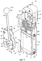
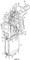
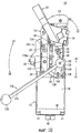
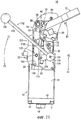
Фиг.1 - перспективное изображение внешнего вида зажимного устройства, в соответствии с одним осуществлением настоящего изобретения;Figure 1 is a perspective view of the appearance of a clamping device, in accordance with one embodiment of the present invention;
Фиг.2 - перспективное покомпонентное изображение, показывающее состояние, в котором фиксирующий механизм отсоединен и удален от зажимного устройства, показанного на Фиг.1;Figure 2 is a perspective exploded view showing a state in which the locking mechanism is detached and removed from the clamping device shown in Figure 1;
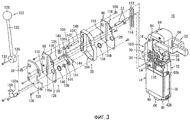
Фиг.3 - перспективное покомпонентное изображение фиксирующего механизма, отсоединенного от зажимного устройства, показанного на Фиг.2;Figure 3 is an exploded perspective view of a locking mechanism detached from the clamping device shown in Figure 2;
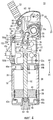
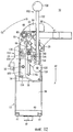
Фиг.4 - изображение поперечного сечения в вертикальном направлении, показывающее разжатое состояние зажимного устройства на Фиг.1;Figure 4 is a cross-sectional image in a vertical direction, showing the expanded state of the clamping device in Figure 1;
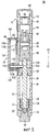
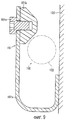
Фиг.5 - изображение поперечного сечения, полученного по линии V - V на Фиг.1;5 is a cross-sectional image obtained along the line V - V in figure 1;
Фиг.6 - перспективное изображение, представленное с другого направления и показывающее состояние, при котором часть первого кожуха отсоединена, и открыт вид на коленно-рычажный механизм и внутреннюю часть фиксирующего механизма зажимного устройства на Фиг.1;6 is a perspective view, presented from a different direction and showing the state in which part of the first casing is disconnected, and a view of the knee-lever mechanism and the inner part of the locking mechanism of the clamping device in figure 1 is open;
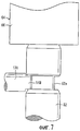
Фиг.7 - увеличенное изображение, показывающее соединенную область между штоком поршня и направляющей штангой на Фиг.6;Fig.7 is an enlarged image showing the connected area between the piston rod and the guide rod in Fig.6;
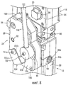
Фиг.8 - увеличенное перспективное изображение, показывающее область фиксирующего механизма, при этом стопор установлен на нем в соответствии с модифицированным примером;Fig. 8 is an enlarged perspective view showing an area of the locking mechanism, wherein the stopper is mounted on it in accordance with a modified example;
Фиг.9 - изображение поперечного сечения, показывающее положение, при котором рукоятка фиксируется стопором на Фиг.8;Fig.9 is a cross-sectional image showing the position at which the handle is fixed by a stopper in Fig.8;
Фиг.10 - частичный вид сбоку, на котором представлено разжатое состояние зажимного устройства, показанного на Фиг.4;Figure 10 is a partial side view showing the expanded state of the clamping device shown in Figure 4;
Фиг.11 - частичный вид сбоку, на котором представлено состояние, при котором кронштейн зажимного устройства, показанного на Фиг.10, повернут на заданный угол;11 is a partial side view showing a state in which the bracket of the clamping device shown in FIG. 10 is rotated by a predetermined angle;
Фиг.12 - частичный вид сбоку, на котором представлено зажатое состояние зажимного устройства, при котором кронштейн, показанный на Фиг.11, еще более повернут.12 is a partial side view showing the clamped state of the clamping device, in which the bracket shown in FIG. 11 is further rotated.
НАИЛУЧШИЙ СПОСОБ ОСУЩЕСТВЛЕНИЯ ИЗОБРЕТЕНИЯBEST MODE FOR CARRYING OUT THE INVENTION
На Фиг.1 ссылочной цифрой 10 показано зажимное устройство в соответствии с одним осуществлением настоящего изобретения.1,
Как показано на Фиг.1 - Фиг.6, зажимное устройство 10 содержит корпус (основной корпус) 16, имеющий плоскую форму и образованный из первого и второго кожухов 12, 14, цилиндрическую секцию 18, подсоединенную к нижнему торцу корпуса 16, кронштейн (зажимной кронштейн) 22, подсоединенный к прямоугольному упорному подшипнику 20 и выступающий снаружи из корпуса 16, и фиксирующий механизм (переключающий механизм) 24, расположенный на боковой поверхности корпуса 16, который обеспечивает произвольное переключение между зажатым и разжатым состояниями обрабатываемой детали (не показана) кронштейном 22.As shown in FIGS. 1 to 6, the
На боковой поверхности корпуса 16 образовано несколько отверстий 30 для установки кожуха 28, образующего фиксирующий механизм 24. Кожух 28 зафиксирован в отверстии 30 крепежным болтом 26. Кроме того, на боковой поверхности корпуса 16 образовано несколько установочных отверстий 34, в которые вставлены установочные шпильки 32, обеспечивающие закрепление кожуха 28 при его подсоединении (см. Фиг.2). Кроме того, упомянутые выше отверстия 30 и установочные отверстия 34 могут использоваться также в том случае, когда к зажимному устройству 10 прикрепляются другие элементы.
Цилиндрическая секция 18 содержит полую цилиндрическую трубку 38, имеющую в нем камеру цилиндра 36 и торцевой блок 40, подсоединенный к одному торцу цилиндрической трубки 38 и закрывающий камеру цилиндра 36. Кроме того, в осевом направлении в четырех углах цилиндрической трубки 38 и в торцевом блоке 40 выполнены сквозные отверстия (не показаны), в эти сквозные отверстия вставлены и затянуты соединительные болты 41, и тем самым торцевой блок 40 и цилиндрическая трубка 38 соединены в одно целое с корпусом 16.The
На боковой поверхности торцевого блока 40 сформирована пара первых впускных/выпускных каналов рабочего вещества 42а, 42b, через которые вводится и выводится под давлением рабочее вещество (например, сжатый воздух). Первые впускные/выпускные каналы рабочего вещества 42а, 42b сообщаются через соответствующие коммуникационные проходы с камерой цилиндра 36. Первые впускные/выпускные каналы рабочего вещества 42а, 42b размещены навстречу друг к другу на боковых поверхностях торцевого блока 40 так, что они главным образом симметричны относительно оси торцевого блока 40.On the side surface of the
Одна из пар первых впускных/выпускных каналов рабочего вещества 42а, 42b используется избирательно, в то время как в другой неиспользуемый первый впускной/выпускной канал рабочего вещества, например 42b, блокируется заглушкой 44а (см. Фиг.4).One of the pairs of the first inlet / outlet channels of the
Кроме того, в самом центре торцевого блока 40 через винтовое отверстие, которое проходит в его осевом направлении, продевается уплотняющий болт 46. На торце уплотняющего болта 46 установлен демпфирующий элемент 50, изготовленный из каучукового материала, например из уретанового каучука или подобного ему материала.In addition, at the very center of the
Внутри цилиндрической трубки 38 расположен поршень 48, который может смещаться вдоль камеры цилиндра 36, причем один конец поршневого штока 52 подсоединен к центральной части поршня 48. Через кольцевую канавку на внешней периферической поверхности поршня 48 установлены соответственно пары уплотнений поршня 54 и уплотнительных колец 56.A
В этом случае при смещении поршня 48 в направлении от корпуса 16 (в направлении по стрелке А1) конечное положение торца при смещении (нижнее предельное положение) поршня 48 регулируется примыканием поршня 48 к демпфирующему элементу 50, который расположен на уплотняющем болте 46, и затем удары, создаваемые при примыкании поршня 48, поглощаются демпфирующим элементом 50.In this case, when the
Далее, на другой торцевой стороне поршневого штока 52, который подсоединен к шарнирному блоку 66 (описан позднее), образована обводная канавка (канавка) 52а, которая имеет углубленную кольцеобразную форму. В обводную канавку 52а входит направляющий стержень (соединительный элемент) 138, который образует часть фиксирующего механизма 24.Further, on the other end side of the
Первый кожух 12 и второй кожух 14, образующие корпус 16, имеют асимметричную форму, причем первый кожух 12 и второй кожух 14 собраны в единое целое. Непосредственно на нижнем торце первого кожуха 12 образован выступающий элемент 58, который выступает главным образом в горизонтальном направлении и который выполняет функцию крышки штанги.The
Далее, на нижнем торце первого кожуха 12 образована пара вторых впускных/выпускных каналов рабочего вещества 60а, 60b, через которые вводится и выводится под давлением рабочее вещество (например, сжатый воздух). Вторые впускные/выпускные каналы рабочего вещества 60а, 60b сообщаются с камерой цилиндра 36 через коммуникационные проходы и размещены навстречу друг другу так, что они главным образом симметричны относительно оси первого кожуха 12. Кроме того, аналогично первым впускным/выпускным каналам рабочего вещества 42а, 42b, один из этой пары вторых впускных/выпускных каналов рабочего вещества 60а, 60b используется избирательно, в то время как другой неиспользуемый второй впускной/выпускной канал рабочего вещества 60b блокируется заглушкой 44b.Further, at the lower end of the
Кроме того, вдоль осевого направления, соответственно на поверхностях внутренних стенок первого кожуха 12 и второго кожуха 14, образованы обращенные друг к другу направляющие канавки 62 (см. Фиг.4). Шарнирное соединение 64, подсоединенное к другому концу поршневого штока 52, расположено с возможностью скольжения по направляющим канавкам 62. То есть шарнирное соединение 64 линейно направляется по направляющим канавкам 62 внутри корпуса 16.In addition, along the axial direction, respectively, on the surfaces of the inner walls of the
Шарнирное соединение 64 состоит из шарнирного блока 66, имеющего вилкообразную часть, разделенную на параллельные части с заранее заданным расстоянием между ними, и шарнирной оси 68, вставленной через отверстие, которое образовано в вилкообразных частях, и наряду с этим снабжено коленно-рычажным механизмом 70 для преобразования линейного перемещения поршневого штока 52 во вращательное движение кронштейна 22.The
Кроме того, имеется пара расцепляющих выступов 72, каждый из которых выдвигается вверх на вилкообразные части шарнирного блока 66. Расцепляющие выступы 72 выступают соответственно из каналов, образованных на верхних частях первого и второго кожухов 12, 14, когда рабочая деталь зажимается кронштейном 22. С другой стороны, второй конец поршневого штока 52 проходит внутрь и соединяется с нижним концом шарнирного блока 66.In addition, there is a pair of releasing
Коленно-рычажный механизм 70 содержит накладку шарнирного звена 74, подсоединенную между вилкообразными частями шарнирного соединения 64 посредством шарнирной оси 68, и опорный рычаг 78, установленный в осевом направлении с возможностью свободного вращения в отверстиях 76, образованных соответственно в первом и втором кожухах 12, 14.The knee-
Накладка шарнирного звена 74 установлена между шарнирным соединением 64 и опорным рычагом 78 и выполняет функцию связи шарнирного соединения 64 с опорным рычагом 78. На накладке шарнирного звена 74 образована пара каналов, отстоящих друг от друга на заранее заданное расстояние. Накладка шарнирного звена 74 подсоединена к другому концу поршневого штока 52 посредством шарнирной оси 68, которая поддерживается в осевом направлении одним из каналов и шарнирным соединением 64, при этом накладка шарнирного звена 74 подсоединена также к опорному рычагу 78 посредством шарнирного пальца 80, поддерживаемого в осевом направлении в другом канале.An overlay of the articulated
Опорный рычаг 78 содержит вилкообразную опорную часть 82, в которой закреплен в осевом направлении шарнирный палец 80, и пару упорных подшипников 20, которые проходят в направлениях, перпендикулярных к оси поршневого штока 52, и выступают из корпуса 16 через отверстия 76. Кронштейн 22, который зажимает не показанную здесь обрабатываемую деталь, устанавливается с возможностью отсоединения на упорном подшипнике 20. Кроме того, опорный рычаг 78 располагается так, что он вращается как единое целое с кронштейном 22.The
Более конкретно, линейное перемещение поршневого штока 52 передается на опорный рычаг 78 через шарнирное соединение 64 и накладку шарнирного звена 74, тем самым опорный рычаг 78 поворачивается на заданный угол и смещается в состояние, при котором опорный рычаг 78 устанавливается в отверстиях 76 корпуса 16. Благодаря этому поворачивается кронштейн 22, установленный на опорном рычаге 78.More specifically, the linear movement of the
С другой стороны, на боковых поверхностях первого кожуха 12 и второго кожуха 14 установлены пластины 84 так, что они обращены к отверстиям 76, через которые вставляются упорные подшипники 20 опорного рычага 78. В пластинах 84 проделаны сквозные каналы 86, через которые вставлены упорные подшипники 20.On the other hand,
Кроме того, внутри первого и второго кожуха 12 и 14 в выточках на их верхней стороне, вблизи коленно-рычажного механизма 70, расположен свободно вращающийся направляющий ролик 88. Направляющий ролик 88 устанавливается с возможностью свободного вращения шпилькой 90, а внутри направляющего ролика 88 по направлению вдоль его окружности установлено несколько игольчатых подшипников 92. То есть направляющий ролик 88 расположен так, что он может плавно вращаться под действием вращения игольчатых подшипников 92. Кроме того, направляющий ролик 88 смещается с вращением за счет контакта с искривленной поверхностью накладки шарнирного звена 74, которая является частью коленно-рычажного механизма 70.In addition, a freely
Кроме того, на верхней части корпуса 16 установлена верхняя крышка 94, которая закрывает расцепляющие выступы 72. Верхняя крышка 94 выполнена из упругого материала, такого, например, как каучук или ему подобного материала. Что касается расцепляющих выступов 72, то верхняя часть корпуса 16, содержащая расцепляющие выступы 72, которые выступают из открытых каналов, окружена и полностью закрыта верхней крышкой 94. Дополнительно к этому, когда расцепляющие выступы 72 срабатывают, то верхняя крышка 94 ударяется сверху не показанным здесь капроновым молотком или аналогичным предметом, сразу после этого смещением вниз расцепляющих выступов 72 зажатое состояние зажимного устройства 10 разблокируется и тем самым состояние разжатия может быть восстановлено.In addition, an
Фиксирующий механизм 24 содержит раму 100, закрытую первой и второй плоскими крышками 96, 98, рукоятку (рабочий элемент) 102, которая закреплена с возможностью свободного вращения относительно рамы 100 и которая может быть захвачена и приводится в движение оператором, и передаточную секцию 104, расположенную внутри рамы 100, которая передает движущее усилие от рукоятки 102 через коленно-рычажный механизм 70 к кронштейну 22.The
Рама 100 имеет полую часть, первую и вторую плоские крышки 96, 98, в основном, одинаковой формы, установленные по обеим боковым поверхностям кожуха болтами 106. Коробчатый кожух 28 состоит из первой и второй плоской крышки 96, 98 и рамы 100.The
В кожухе 28 установлена вторая плоская крышка 98 так, что она образует одну сторону корпуса 16 зажимного устройства 10. На боковой поверхности корпуса 16 имеется прорезь рукоятки 110, обращенная открытой стороной к кожуху 28. Прорезь рукоятки 110 имеет удлиненную форму заранее заданной длины в осевом направлении корпуса 16, а между боковой поверхностью корпуса 16 и второй плоской крышкой 96, обращенной к прорези рукоятки 110, установлено пылезащитное уплотнение 112.A second
В случае, когда фиксирующий механизм 24 не установлен, в прорези рукоятки 110 устанавливается удлиненная пылезащитная крышка (крышка) 113, которая блокирует прорезь рукоятки 110 так, что сообщение между внутренней частью корпуса 16 и окружающей средой прерывается (см. Фиг.2).In the case where the
Пылезащитное уплотнение 112 выполнено из упругого материала, такого, например, как каучук или ему подобного материала, для поддержания герметичного состояния между корпусом 16 и кожухом 28. Кроме того, в центре пылезащитного уплотнения 112 образована соответствующая прорези рукоятки 110 удлиненная прорезь 114 так, что удлиненная прорезь 114 и прорезь рукоятки 110 контактируют друг с другом.The
Далее, первая и вторая плоские крышки 96, 98 расположены навстречу друг другу, а между ними находится рама 100. В центральных частях первой и второй плоской крышки 96, 98 образованы направляющие каналы соответственно 116а, 116b, которые соответствуют прорези рукоятки 110. В частности, направляющие каналы 116а, 116b проходят по прямой линии относительно прорези рукоятки 110 и удлиненной прорези 114 и взаимно контактируют друг с другом.Further, the first and second flat covers 96, 98 are arranged towards each other, and between them there is a
Кроме того, в первой и второй плоской крышке 96, 98 образованы соответственно пары каналов под шпильки 118, отстоящие на заранее заданное расстояние от центра направляющих каналов 116а, 116b, и в отверстия под шпильки 118 вставлены установочные шпильки 32. Установочные шпильки 32, введенные в установочные отверстия 34 корпуса 16, закрепляют кожух 28, содержащий первую и вторую плоские крышки 96, 98, относительно боковой поверхности корпуса 16 и тем самым образуют зажимное устройство 10.In addition, in the first and second
В частности, как показано на Фиг.3 и Фиг.5, направляющие каналы 116а, 116b кожуха 28 установлены так, чтобы прорезь рукоятки 110 корпуса 16 совпадала с продольной прорезью 114 пылезащитного уплотнения 112.In particular, as shown in FIGS. 3 and 5, the
Кроме того, после того как кожух 28 установлен на боковой поверхности корпуса 16 установочными шпильками 32, в посадочные отверстия 30 корпуса 16 устанавливаются крепежные болты 26, которые вводятся через каналы в первой и второй плоских крышках 96, 98 и раме 100. Соответственно, кожух 28 скрепляется в одно целое с боковой поверхностью корпуса 16.In addition, after the
Далее, на первой плоской крышке 96 установлена пластина 120, которая имеет, в основном, такую же самую форму, что и первая плоская крышка 96, тем самым направляющий канал 116а первой плоской крышки 96 закрывается и блокируется пластиной 120. Пластина 120 вырезана так, чтобы не касаться ступицы 126 рукоятки 102 (см. Фиг.1 и Фиг.2).Further, a
Рукоятка 102 содержит вал 122, установленный на одной стороне первой плоской крышки 96, которая закрывает кожух 28, и имеющий удлиненную форму в осевом направлении, ступицу 126, расположенную на одном конце вала 122 и прикрепленную к рычагу рукоятки (первая рычажная передача) 124, который образует передаточную секцию 104, и сферическую ручку 128, укрепленную на другом конце вала 122.The
Ступица 126 расположена так, что она обращена к крепежному каналу 129 первой плоской крышки 96, при этом на ее торцевой поверхности установлено несколько шпилек 130. Шпильки 130 закрепляют рукоятку 102, содержащую ступицу 126 и рычаг рукоятки 124, введением этих шпилек в рычаг рукоятки 124 (описано позднее), а также регулируют относительное смещение этих деталей в направлении вращения.The
Кроме того, через центральную часть ступицы 126 вставляется крепежный болт 132 и тем самым рукоятка 102 с находящейся на ней ступицей 126 подсоединяется крепежным болтом 132 к передаточной секции 104.In addition, a fixing
Передаточная секция 104, расположенная внутри рамы 100, содержит рычаг рукоятки 124, к которому подсоединена ступица 126 рукоятки 102, плоский стержень (вторая рычажная передача) 136, укрепленный в осевом направлении посредством рычажной шпильки 134 на рычаге рукоятки 124, и пару первого и второго ползунов 140, 142, установленных на конце плоского стержня 136 посредством направляющего стержня 138.The
В крепежные отверстия 129 первой и второй плоских крышек 96, 98 вставлены кольцевые выступы 144, которые выступают по сторонам одного конца рычага рукоятки 124 и закреплены на нем с возможностью вращения посредством кольцевых вкладышей 146. Вкладыши 146 расположены по сторонам соответственно первой плоской крышки 96 и второй плоской крышки 98.
Кроме того, другому концу рычага рукоятки 124 придана вилкообразная форма, причем в него вставлен один конец плоского стержня 136 и закреплен с возможностью вращения в осевом направлении рычажной шпилькой 134, вставленной через другой конец рычага рукоятки 124. В частности, плоский стержень 136 закреплен и может смещаться на заданный угол относительно рычага рукоятки 124 вокруг точки закрепления или оси шарнира, определенной рычажной шпилькой 134.In addition, a fork-shaped shape is provided to the other end of the lever of the
Один конец плоского стержня 136 закреплен в осевом направлении рычагом рукоятки 124, в то время как в другой его конец, перпендикулярно к продольному направлению плоского стержня 136, вставлен направляющий стержень 138.One end of the
Один конец направляющего стержня 138 расположен на боковой стороне первой плоской крышки 96. На конце направляющего стержня 138 установлен первый ползун 140, имеющий цилиндрическую форму, при этом первый ползун 140 входит в зацепление с направляющим каналом 116а. С другой стороны, второй конец направляющего стержня 138 размещен на боковой стороне второй плоской крышки 98 и вставлен во второй ползун цилиндрической формы 142, и, кроме того, вставлен в прорезь рукоятки 110 корпуса 16, проходя при этом через направляющий канал 116b второй плоской крышки 98. В этом случае направляющий стержень 138 устанавливается так, что он становится перпендикулярен к поршневому штоку 52, расположенному внутри корпуса 16.One end of the
Кроме того, на другом конце направляющего стержня 138, где внешняя периферическая поверхность направляющего стержня 138 срезана в форме плоской поверхности, образована прорезь 148. Прорезь 148, которая имеет суживающуюся форму, в основном, с прямоугольным поперечным сечением входит в зацепление с близлежащей канавкой 52а в поршневом штоке 52 (см. Фиг.7). В частности, при смещении поршневого штока 52 в осевом направлении (направления по стрелкам А1 и А2) направляющий стержень 138 смещается вместе с ним.In addition, at the other end of the
Другими словами, поршневой шток 52 может смещаться при смещении направляющего стержня 138. Однако при установке другим образом направляющий стержень 138 не смещается в осевом направлении (направления по стрелкам А1 и А2) поршневого штока 52 по отношению к поршневому штоку 52 и всегда смещается вместе с ним как единое целое.In other words, the
Первый ползун 140 входит внутрь направляющего канала 116а первой плоской крышки 96 и продолжает дальше перемещаться вдоль направляющего канала 116а. Направляющий канал 116а закрывается и блокируется наложением на него пластины 120.The
Второй ползун 142 входит внутрь направляющего канала 116b второй плоской крышки 98 и продолжает дальше перемещаться вдоль направляющего канала 116b. В частности, первый и второй ползуны 140, 142 перемещаются в осевом направлении вдоль направляющих каналов 116а, 116b при смещении направляющего стержня 138. Другими словами, первый и второй ползуны 140, 142 функционируют как регулирующие механизмы, предотвращающие излишнее смещение направляющего стержня 138 вдоль направляющих каналов 116а, 116b.The
Более детально, рычаг рукоятки 124 поворачивается вращением рукоятки 102 и наряду с этим посредством плоского стержня 136 смещается вверх и вниз направляющий стержень 138 (в направлениях по стрелкам А1 и А2) вдоль направляющих каналов 116а, 116b, и управляясь при этом ползунами.In more detail, the lever of the
С другой стороны, на пластине 120 установлен стопор 150, который выступает в направлении непосредственно от первой плоской крышки 96 и регулирует вращательное смещение рукоятки 102. Стопор 150 имеет L-образную форму поперечного сечения и по мере удаления в направлении от пластины 120 изгибается вверх и проходит параллельно пластине 120. Более конкретно, стопор 150 расположен так, что он отделен на заранее заданное расстояние от пластины 120.On the other hand, a
Кроме того, после того как рукоятка 102 поворачивается оператором и устанавливается в соответствии с положением стопором 150, рукоятка 102 фиксируется выступом 150а, который выступает по направлению к пластине 120, и тем самым регулируется вращательное смещение рукоятки 102.In addition, after the
Помимо этого, вышеупомянутый стопор 150 не ограничен необходимостью выполнения как единого целого. Например, как показано на Фиг.8 и Фиг.9, может применяться двухэлементный стопор 151, который состоит из основного корпуса стопора 151а, образованного изогнутой пластиной, и стопорного блока 151b, установленного на одной стороне пластины 120 основного корпуса стопора 151а.In addition, the
Основной корпус стопора 151а изогнут вверх и постепенно принимает форму плоской поверхности, в то время как стопорный блок 151b прикреплен к верхнему концу основного корпуса стопора 151а. Стопорный блок 151b выполнен, например, из каучукового материала, имеет, в основном, треугольную форму в поперечном сечении и закреплен на поверхности внутренней стенки основного корпуса стопора 151а посредством болта 151с, выступая при этом на заданную высоту по направлению к пластине 120. Стопорный блок 151b не ограничен тем, что он выполнен из каучукового материала, он может быть выполнен также из такого упругого материала, как резина, или аналогичного ему материала, или из металла.The main body of the
Кроме того, когда рукоятка 102 поворачивается оператором и устанавливается в соответствии с положением стопора 151, рукоятка 102 сначала упирается в стопорный блок 151b и проходит за стопорный блок 151b, а затем вал 122 рукоятки 102 упирается в стопорный блок 151b. Соответственно, рукоятка 102 входит в зацепление со стопорным блоком 151b и стопорится им, и тем самым регулируется дальнейшее вращение рукоятки 102.In addition, when the
В упомянутом выше стопоре 151 могут быть успешно проведены операции по техническому обслуживанию, поскольку стопорный блок 151b может быть легко заменен в случае, когда стопорный блок 151b будет изношен из-за повторяющихся контактов с рукояткой 102.Maintenance operations can be successfully performed in the
Индикаторный механизм 153 содержит детектируемую часть 154, установленную на шарнирном блоке 66 посредством собачки 152, а также пару датчиков 158а, 158b, которые определяют положение детектируемой части 154 и размещены внутри держателя 156, расположенного на одной стороне корпуса 16. Дополнительно к этому, датчиками 158а, 158b обнаруживается изменение в импедансе, которое возникает, когда детектируемая часть 154 находится вблизи них, и тем самым считыванием положения детектируемой части 154 может быть обнаружено вращательное положение кронштейна 22 (т.е. положение, при котором кронштейн 22 повернут).The
Зажимное устройство 10, в соответствии с этим осуществлением настоящего изобретения, сконструировано, в основном, как описано выше. Далее будет дано объяснение работы и действий зажимного устройства 10.The clamping
Сначала зажимное устройство 10 укреплено в заданном положении не показанным здесь фиксирующим механизмом, а к первому и второму впускному/выпускному каналам рабочего вещества 42а, 60а подсоединены соответственно трубки или подобные элементы (не показаны), которые подсоединены к источнику рабочего вещества под давлением. На Фиг.1 показано зажимное устройство 10 в зажатом состоянии, а на Фиг.4 показано зажимное устройство 10 в разжатом состоянии. В дальнейшем упомянутое выше разжатое состояние будет рассматриваться как начальное состояние зажимного устройства 10.First, the clamping
В начальном состоянии зажимного устройства 10, показанного на Фиг.4 и Фиг.10, давление рабочего вещества от не показанного источника рабочего вещества под давлением поступает на первый впускной/выпускной канал 42а и рабочее вещество вводится в камеру цилиндра 36. Под действием рабочего вещества, которое вводится в камеру цилиндра 36, поршень 48 поджимается к корпусу 16 (в направлении по стрелке А2) и поршень 48 перемещается по камере цилиндра 36. Кроме того, при смещении поршня 48 и поршневого штока 52 смещается со скольжением шарнирный блок 66, направляемый при этом направляющими канавками 62.In the initial state of the
Через шток поршня 52 и шарнирное соединение 64 на коленно-рычажный механизм 70 передается линейное перемещение поршня 48, которое преобразуется во вращательное движение кронштейна 22 под действием вращения опорного рычага 78, который является составной частью коленно-рычажного механизма 70. В частности, направленная вверх сила давления (в направлении по стрелке А2) действует на накладку шарнирного звена 74 и шарнирное соединение 64, подсоединенное к поршневому штоку 52, в соответствии с линейным перемещением поршня 48.A linear movement of the
Кроме того, сила давления, действующая на накладку шарнирного звена 74, заставляет вращаться накладку шарнирного звена 74 на заданный угол относительно центра шарнира, определенного шарнирной осью 68, тем самым поворачивает опорный рычаг 78 по часовой стрелке (в направлении по стрелке В1), что является результатом его связи с накладкой шарнирного звена 74. Другими словами, кронштейн 22 поворачивается на заранее заданный угол относительно центра шарнира, определенного упорными подшипниками 20 опорного рычага 78.In addition, the pressure force acting on the pad of the
Таким образом, когда кронштейн 22 поворачивается, искривленная поверхность накладки шарнирного звена 74 приходит в контакт с направляющим роликом 88, и пока сохраняется состояние контакта с искривленной поверхностью, направляющий ролик 88 вращается против часовой стрелки вокруг шпильки 90. Кроме того, кронштейн 22 поворачивается в направлении (направление по стрелке В1) к не показанной здесь обрабатываемой детали (см. Фиг.11), тем самым примыканием дуговидных выступов 78а опорного рычага 78 к пластине (не показана), подсоединенной к корпусу 16, вращательное смещение кронштейна 22 через поршневой шток 52 и коленно-рычажный механизм 70 останавливается (см. Фиг.12).Thus, when the
В результате, как показано на Фиг.12, зажимное устройство 10 переходит в состояние зажима, при котором кронштейн 22 повернут по часовой стрелке (в направлении по стрелке В1) на заранее заданный угол.As a result, as shown in FIG. 12, the clamping
В это же время, детектируемая часть 154, являющаяся частью измерительного механизма 153, смещается вверх вместе с шарнирным блоком 66, и детектированием изменения в импедансе одним из сенсоров 158а, расположенным внутри держателя 156, подтверждается, что кронштейн 22 находится в зажатом состоянии.At the same time, the detected
В этом случае пара расцепляющих выступов 72, образованных на верхней части шарнирного блока 66, приходят в состояние, при котором расцепляющие выступы 72 выступают вверх на заданную длину через открытые каналы в корпусе 16. Соответственно, смещением расцепляющих выступов 72 сверху вниз (в направлении по стрелке А1), например, оператором, непосредственно ударяющим по верхней крышке 94 сверху с использованием не показанного пластикового молотка или аналогичного предмета, состояние зажима зажимного устройства 10 может быть прекращено и переведено в разжатое состояние.In this case, the pair of
С другой стороны, в состоянии зажима, показанном на Фиг.6 и Фиг.12, подачей рабочего вещества во второй впускной/выпускной канал 60а переключающим действием не показанного направляющего распределителя поршень 48 смещается в направлении (направление по стрелке А1) от корпуса 16. Кроме того, при движении сверху вниз поршневого штока 52 вместе с поршнем 48 опорный рычаг 78 поворачивается в противоположном направлении (направление по стрелке В2) посредством накладки шарнирного звена 74, которая входит в коленно-рычажный механизм 70. Наряду с этим, кронштейн 22 поворачивается в направлении от обрабатываемой детали (не показана).On the other hand, in the clamping state shown in FIGS. 6 and 12, by supplying the working medium to the second inlet /
Кроме того, примыканием поршня 48 к демпфирующему элементу 50 уплотняющего болта 46, который проходит через торцевой блок 40, регулируется дальнейшее смещение поршня 48, и поворотное смещение кронштейна 22 поршневым штоком 52 и коленно-рычажным механизмом 70 останавливается (см. Фиг.10). В результате зажимное устройство 10, как показано на Фиг.4 и Фиг.10, устанавливается в разжатое состояние, в котором кронштейн 22 поворачивается против часовой стрелки (в направлении по стрелке В2) на заранее заданный угол.In addition, by adjoining the
Далее, детектируемая часть 154 смещается вместе с шарнирным блоком 66 и детектируется другим расположенным внизу датчиком 158b, тем самым детектирующим механизмом 153 выявляется тот факт, что кронштейн 22 находится в разжатом состоянии.Further, the detecting
Далее объяснение будет проводиться для случая, в котором состояние зажима переключается срабатыванием кронштейна 22 вручную посредством фиксирующего механизма 24 в упомянутом выше зажимном устройстве 10. В разжатом состоянии, показанном на Фиг.4 и Фиг.10, рукоятка 102 поворачивается на заранее заданный угол, тем самым вал 122 устанавливается в соответствии с положением стопора 150.Next, an explanation will be given for the case in which the clamping state is switched by manually actuating the
Сначала, в разжатом состоянии, оператор захватывает ручку 128 рукоятки 102 и поворачивает рукоятку 102 по часовой стрелке (в направлении по стрелке С1) на заданный угол вокруг ступицы 126. Благодаря этому плоский стержень 136 поворачивается рычагом рукоятки 124 и направляющий стержень 138 смещается вверх, направляясь при этом первым и вторым ползунами 140, 142. В результате поршневой шток 52, с которым сцеплен направляющий стержень 138, также смещается вверх и кронштейн 22 поворачивается посредством коленно-рычажного механизма 70, приходя тем самым в состояние, при котором начинается зажим (см. Фиг.11).First, in the extended state, the operator grabs the
Кроме того, дальнейшим вращением рукоятки 102 по часовой стрелке (в направлении по стрелке С1) направляющий стержень 138 смещается далее вверх вдоль направляющих каналов 116а, 116b. Наряду с этим, поскольку поршневой шток 52 и поршень 48 смещаются вверх, кронштейн 22 при вращении смещается еще более, в результате чего возникает состояние зажима, обеспечивающее зажим обрабатываемой детали.Furthermore, by further turning the
Более конкретно, вращением рукоятки 102 направляющий стержень 138 смещается вверх вдоль направляющих каналов 116а, 116b первой и второй плоских крышек 96, 98 посредством накладки шарнирного звена 74 и рычага рукоятки 124, которые являются частью передаточной секции 104, тем самым поршневой шток 52, который подсоединен к направляющему стержню 138, может быть смещен вместе с ними. Соответственно, кронштейн 22 может быть при вращении смещен через коленно-рычажный механизм 70 смещением поршневого штока 52, переходя тем самым в зафиксированное состояние, при котором обрабатываемая деталь будет зажата.More specifically, by rotating the
С другой стороны, в положении, когда обрабатываемая деталь зафиксирована кронштейном 22, захватом и поворотом оператором рукоятки 102 против часовой стрелки (в направлении по стрелке С2), т.е. в направлении, противоположном описанному выше направлению, направляющий стержень 138, являющийся частью фиксирующего механизма 24, будет смещен вниз по направляющим каналам 116а, 116b, при этом поршневой шток 52, направляемый первым и вторым ползунами 140, 142, также сместится вниз вместе с ними. В результате кронштейн 22 сместится с вращением против часовой стрелки (в направлении по стрелке В2) посредством коленно-рычажного механизма 70, освобождая тем самым зафиксированное кронштейном 22 состояние обрабатываемой детали.On the other hand, in the position where the workpiece is fixed by the
В вышеизложенном способе настоящего осуществления изобретения фиксирующий механизм 24 устанавливается на боковой поверхности корпуса 16, являющегося частью зажимного устройства 10. Оператором, поворачивающим рукоятку 102 фиксирующего механизма 24, направляющий стержень 138 может быть смещен посредством передаточной секции 104, подсоединенной к рукоятке 102, вдоль направляющих каналов 116а, 116b кожуха 28.In the above method of the present invention, the
Соответственно, поршневой шток 52, который подсоединен к направляющему стержню 138, может быть смещен в осевом направлении (направление по стрелкам А1 и А2) и под действием смещения поршневого штока 52 кронштейн 22 смещается с вращением коленно-рычажным механизмом 70, тем самым состояние зажима кронштейном 22 обрабатываемой детали и его разжатое состояние легко может быть изменено вручную.Accordingly, the
Кроме того, фиксирующий механизм 24 расположен на боковой поверхности корпуса 16 с возможностью отсоединения, и он может быть легко отсоединен от корпуса 16 простым откручиванием и удалением крепежных болтов 26, вставленных через кожух 28. С другой стороны, после установки кожуха 28 в корпусе 16 установочными штифтами 32 кожух 28 может быть легко зафиксирован установкой крепежных болтов 26 в отверстия 30.In addition, the
Таким образом, поскольку фиксирующий механизм 24, который обеспечивает возможность ручного переключения состояния зажима кронштейном 22, может быть легко смонтирован и отсоединен от собственно зажимного устройства 10, то оператор может решать, требуется или не требуется фиксирующий механизм 24, и избирательно использовать этот механизм в зависимости от среды применения зажимного устройства 10. В результате управляемое вручную зажимное устройство, в котором обеспечена возможность ручного поворота кронштейна 22, не должно создаваться отдельно от зажимного устройства 10, которое приводится в движение источником сжатого вещества и по этой причине стоимость такого оборудовании может быть снижена.Thus, since the
Кроме того, когда фиксирующий механизм 24 отсоединяется и вынимается из корпуса 16, являющегося частью зажимного устройства 10, в отверстие рукоятки 110, которое открывается на боковой поверхности корпуса 16, устанавливается пылезащитный чехол 113, и тем самым отверстие рукоятки 110 закрывается. Соответственно, внутренняя часть корпуса 16 может быть плотно закрыта и может быть обеспечена ее герметичность.In addition, when the
Зажимное устройство в соответствии с настоящим изобретением не ограничено описанным выше осуществлением, и само собой разумеется, что могут быть выбраны различные другие структуры, которые не отклоняются от неотъемлемых особенностей и сущности настоящего изобретения.The clamping device in accordance with the present invention is not limited to the implementation described above, and it goes without saying that various other structures can be selected that do not deviate from the inherent features and essence of the present invention.
Claims (8)
основной корпус (16);
цилиндр (18), подсоединенный к упомянутому основному корпусу (16) и имеющий поршень (48), который смещается в осевом направлении под действием давления рабочего вещества;
переключающий механизм (24), который установлен с возможностью отсоединения от упомянутого основного корпуса (16), имеющий рабочий элемент (102), управляемый оператором, и передаточную секцию (104) для передачи движущего усилия, приложенного упомянутым рабочим элементом (102) к упомянутому цилиндру (18), упомянутый переключающий механизм (24), смещающий упомянутый поршень (48) в осевом направлении срабатыванием упомянутого рабочего элемента (102) посредством упомянутой передаточной секции (104) для переключения между зажатым и разжатым состояниями упомянутой обрабатываемой детали,
отличающееся тем, что упомянутая передаточная секция (104) содержит первую рычажную передачу (124), подсоединенную к упомянутому рабочему элементу (102), которая может смещаться с поворотом вместе с упомянутым рабочим элементом (102), вторую рычажную передачу (136), закрепленную в осевом направлении с возможностью поворота относительно упомянутой первой рычажной передачи (124), и соединительный элемент (138), закрепленный на одном конце упомянутой второй рычажной передачи (136) и смещаемый параллельно направлению смещения упомянутого поршня (48).1. A clamping device in which the linear movement of the cylinder is converted into rotational motion by a knee-lever mechanism, and the workpiece is clamped by a clamping bracket, comprising:
main body (16);
a cylinder (18) connected to said main body (16) and having a piston (48), which is axially displaced by the pressure of the working substance;
a switching mechanism (24) that is detachably mounted from said main body (16) having an operating element (102) controlled by an operator and a transmission section (104) for transmitting a driving force applied by said working element (102) to said cylinder (18) said switching mechanism (24) axially biasing said piston (48) by activating said working element (102) by said transmission section (104) for switching between the clamped and unclenched states of said removed workpiece
characterized in that said transmission section (104) comprises a first link gear (124) connected to said working element (102), which can be rotatedly displaced together with said working element (102), a second link gear (136) fixed to axially rotatable relative to said first linkage (124), and a connecting element (138) mounted on one end of said second linkage (136) and offset parallel to the direction of displacement of said piston (48).
Applications Claiming Priority (2)
| Application Number | Priority Date | Filing Date | Title |
|---|---|---|---|
| JP2007035074A JP4892668B2 (en) | 2007-02-15 | 2007-02-15 | Clamping device |
| JP2007-035074 | 2007-02-15 |
Publications (2)
| Publication Number | Publication Date |
|---|---|
| RU2009129535A RU2009129535A (en) | 2011-02-20 |
| RU2432251C2 true RU2432251C2 (en) | 2011-10-27 |
Family
ID=39301747
Family Applications (1)
| Application Number | Title | Priority Date | Filing Date |
|---|---|---|---|
| RU2009129535/02A RU2432251C2 (en) | 2007-02-15 | 2008-01-28 | Clamp |
Country Status (8)
| Country | Link |
|---|---|
| US (1) | US8132800B2 (en) |
| EP (1) | EP2111328B1 (en) |
| JP (1) | JP4892668B2 (en) |
| KR (1) | KR101079608B1 (en) |
| CN (1) | CN101616774B (en) |
| RU (1) | RU2432251C2 (en) |
| TW (1) | TWI327948B (en) |
| WO (1) | WO2008099694A1 (en) |
Cited By (1)
| Publication number | Priority date | Publication date | Assignee | Title |
|---|---|---|---|---|
| RU2600782C2 (en) * | 2012-01-27 | 2016-10-27 | СМСи КАБУСИКИ КАИСА | Electric clamp apparatus |
Families Citing this family (33)
| Publication number | Priority date | Publication date | Assignee | Title |
|---|---|---|---|---|
| JP4892668B2 (en) * | 2007-02-15 | 2012-03-07 | Smc株式会社 | Clamping device |
| DE102009048510A1 (en) * | 2009-10-09 | 2011-04-14 | De-Sta-Co Europe Gmbh | jig |
| US8918968B2 (en) * | 2010-11-11 | 2014-12-30 | Delaware Capital Formation, Inc. | Link clamp |
| CN102672634B (en) * | 2011-03-14 | 2014-04-16 | 富泰华工业(深圳)有限公司 | Clamping mechanism |
| US8382083B2 (en) * | 2011-04-14 | 2013-02-26 | Delaware Capital Formation, Inc. | Clamping apparatus |
| DE102011018988A1 (en) * | 2011-04-28 | 2012-10-31 | De-Sta-Co Europe Gmbh | actuator |
| DE102011018987A1 (en) * | 2011-04-28 | 2012-10-31 | De-Sta-Co Europe Gmbh | jig |
| DE102011110129A1 (en) * | 2011-08-15 | 2013-02-21 | De-Sta-Co Europe Gmbh | actuator |
| KR101326835B1 (en) * | 2011-12-06 | 2013-11-07 | 현대자동차주식회사 | Side positioning device of system for assembling body panel |
| US9453521B1 (en) * | 2011-12-30 | 2016-09-27 | Lincoln Global IP | Clamp and method of use |
| US10625382B2 (en) * | 2012-08-01 | 2020-04-21 | Delaware Capital Formation, Inc. | Toggle lever clamp |
| JP5688609B2 (en) * | 2012-09-21 | 2015-03-25 | Smc株式会社 | Position detection device |
| CN104070370B (en) * | 2013-03-25 | 2016-08-03 | 富泰华工业(深圳)有限公司 | Clamping device |
| EP2821181B1 (en) * | 2013-07-02 | 2015-03-04 | UNIVER S.p.A. | Clamping device |
| JP6160922B2 (en) * | 2014-02-24 | 2017-07-12 | Smc株式会社 | Clamping device |
| CN103801890B (en) * | 2014-03-05 | 2015-10-07 | 安徽江淮汽车股份有限公司 | A kind of fixture fixing body and grip device |
| JP6119052B2 (en) * | 2014-04-01 | 2017-04-26 | Smc株式会社 | Clamping device |
| DE202014103575U1 (en) * | 2014-08-01 | 2014-09-02 | Pepperl + Fuchs Gmbh | Inquiry unit for toggle clamps |
| DE102014111344A1 (en) * | 2014-08-08 | 2016-02-11 | De-Sta-Co Europe Gmbh | jig |
| US10800008B2 (en) * | 2015-02-16 | 2020-10-13 | Smc Corporation | Clamp device |
| WO2016162074A1 (en) * | 2015-04-09 | 2016-10-13 | Pneumax S.P.A. | Actuating device of the articulated lever or cam type for the precise positioning of a pivotable arm |
| WO2017016607A1 (en) * | 2015-07-30 | 2017-02-02 | Pneumax S.P.A. | Actuating device of the type provided with an actuating element and means for manually operating the actuating element |
| JP6678957B2 (en) * | 2016-08-23 | 2020-04-15 | Smc株式会社 | Clamping device |
| CN106493663B (en) * | 2016-12-27 | 2018-05-18 | 梧州市东麟宝石机械有限公司 | A kind of machining Rocker arm type clamp device |
| US10882148B2 (en) * | 2017-08-01 | 2021-01-05 | Caromation, Inc. | Pivot unit |
| CN107825192A (en) * | 2017-12-10 | 2018-03-23 | 无锡特恒科技有限公司 | A kind of part pressing device |
| US10596589B2 (en) * | 2018-04-12 | 2020-03-24 | Ford Motor Company | Hold down device and method for securing movable vehicle panels during processing |
| JP6997978B2 (en) * | 2018-10-05 | 2022-01-18 | Smc株式会社 | Clamping device |
| CN110488180A (en) * | 2019-09-24 | 2019-11-22 | 西门子数控(南京)有限公司 | The test equipment of electronic component |
| CN110977058B (en) * | 2020-01-07 | 2021-04-16 | 徐州逸腾机电科技有限公司 | Clamping device for milling spline |
| US11759915B2 (en) | 2021-10-03 | 2023-09-19 | Delaware Capital Formation, Inc. | Pneumatic latch clamp |
| CN114769948B (en) * | 2022-03-23 | 2023-06-23 | 广州海可姆机电科技有限公司 | Welding forming machine tool for automobile sheet metal |
| CN115255802B (en) * | 2022-09-29 | 2022-12-02 | 华英阀业有限公司 | Tool clamp for welding valve |
Family Cites Families (18)
| Publication number | Priority date | Publication date | Assignee | Title |
|---|---|---|---|---|
| JPS6235731A (en) * | 1985-08-09 | 1987-02-16 | Canon Inc | Data signal transmission system |
| SU1602668A1 (en) | 1988-03-18 | 1990-10-30 | Предприятие П/Я Р-6500 | Arrangement for clamping parts |
| DE29516531U1 (en) * | 1995-10-19 | 1995-12-14 | Tuenkers Maschinenbau Gmbh | Toggle clamp device |
| DE19645778C2 (en) * | 1996-11-07 | 1999-07-08 | Sta Co Mettallerzeugnisse Gmbh | Toggle clamp device |
| DE29817335U1 (en) * | 1998-09-26 | 1999-02-18 | Tuenkers Maschinenbau Gmbh | Tensioning device, in particular toggle lever tensioning device, primarily for use in body construction in the motor vehicle industry |
| JP2001001274A (en) * | 1999-06-17 | 2001-01-09 | Smc Corp | Clamp device |
| JP3683447B2 (en) * | 1999-10-15 | 2005-08-17 | Smc株式会社 | Clamping device |
| JP3672782B2 (en) * | 1999-12-08 | 2005-07-20 | Smc株式会社 | Clamping device |
| US6416045B1 (en) * | 2000-07-25 | 2002-07-09 | Norgren Automotive, Inc. | Rotary clamp having predetermined adjustable clamping angles |
| US6880816B1 (en) * | 2000-08-17 | 2005-04-19 | Norgren Automotive, Inc. | Structure for isolating mounting and clamping forces of a power clamp |
| US6612557B2 (en) * | 2001-04-30 | 2003-09-02 | Btm Corporation | Adjustable stroke clamp |
| JP2004090163A (en) | 2002-08-30 | 2004-03-25 | Smc Corp | Clamper |
| ITMI20021914A1 (en) * | 2002-09-10 | 2004-03-11 | Univer Spa | LOCKING DEVICE WITH MANUAL CONTROL LEVER |
| JP2004130453A (en) * | 2002-10-10 | 2004-04-30 | Smc Corp | Clamping device |
| US6877730B2 (en) * | 2003-05-29 | 2005-04-12 | Btm Corporation | Powered clamp |
| DE102004007465A1 (en) * | 2004-02-13 | 2005-09-01 | De-Sta-Co Metallerzeugnisse Gmbh | driving device |
| DE202005004598U1 (en) * | 2005-03-18 | 2006-07-27 | De-Sta-Co Europe Gmbh | jig |
| JP4892668B2 (en) * | 2007-02-15 | 2012-03-07 | Smc株式会社 | Clamping device |
-
2007
- 2007-02-15 JP JP2007035074A patent/JP4892668B2/en active Active
-
2008
- 2008-01-23 TW TW097102445A patent/TWI327948B/en not_active IP Right Cessation
- 2008-01-28 WO PCT/JP2008/051701 patent/WO2008099694A1/en active Application Filing
- 2008-01-28 EP EP08704380.8A patent/EP2111328B1/en not_active Not-in-force
- 2008-01-28 US US12/524,588 patent/US8132800B2/en active Active
- 2008-01-28 RU RU2009129535/02A patent/RU2432251C2/en active
- 2008-01-28 KR KR1020097019145A patent/KR101079608B1/en active IP Right Grant
- 2008-01-28 CN CN200880005013.0A patent/CN101616774B/en active Active
Cited By (1)
| Publication number | Priority date | Publication date | Assignee | Title |
|---|---|---|---|---|
| RU2600782C2 (en) * | 2012-01-27 | 2016-10-27 | СМСи КАБУСИКИ КАИСА | Electric clamp apparatus |
Also Published As
| Publication number | Publication date |
|---|---|
| CN101616774A (en) | 2009-12-30 |
| US20100044942A1 (en) | 2010-02-25 |
| EP2111328B1 (en) | 2013-10-23 |
| JP2008194801A (en) | 2008-08-28 |
| EP2111328A1 (en) | 2009-10-28 |
| KR101079608B1 (en) | 2011-11-03 |
| US8132800B2 (en) | 2012-03-13 |
| JP4892668B2 (en) | 2012-03-07 |
| TWI327948B (en) | 2010-08-01 |
| WO2008099694A1 (en) | 2008-08-21 |
| CN101616774B (en) | 2011-06-15 |
| RU2009129535A (en) | 2011-02-20 |
| KR20090113328A (en) | 2009-10-29 |
| TW200836889A (en) | 2008-09-16 |
Similar Documents
| Publication | Publication Date | Title |
|---|---|---|
| RU2432251C2 (en) | Clamp | |
| US7806393B2 (en) | Clamp apparatus | |
| JP4789006B2 (en) | Clamping device | |
| US6199847B1 (en) | Cylinder apparatus | |
| JP5688582B2 (en) | Clamping device | |
| US6378856B1 (en) | Clamp apparatus | |
| JP3683447B2 (en) | Clamping device | |
| JP2004090163A (en) | Clamper | |
| CN106312669B (en) | Chuck apparatus | |
| EP0862970A2 (en) | Fluid driven clamping device | |
| KR101867975B1 (en) | Welding gun | |
| US20010030096A1 (en) | Actuation device for a friction clutch in a drivetrain | |
| JP2015020262A (en) | Clamp device | |
| JP3785988B2 (en) | Pressure vessel | |
| KR980010139A (en) | How to measure residual pressure of power shift valve for manual transmission |