RU2429503C2 - Inquiry method of measurement of radial velocity - Google Patents
Inquiry method of measurement of radial velocity Download PDFInfo
- Publication number
- RU2429503C2 RU2429503C2 RU2009134883/09A RU2009134883A RU2429503C2 RU 2429503 C2 RU2429503 C2 RU 2429503C2 RU 2009134883/09 A RU2009134883/09 A RU 2009134883/09A RU 2009134883 A RU2009134883 A RU 2009134883A RU 2429503 C2 RU2429503 C2 RU 2429503C2
- Authority
- RU
- Russia
- Prior art keywords
- frequency
- voltage
- output
- phase
- input
- Prior art date
Links
Images

Landscapes
- Radar Systems Or Details Thereof (AREA)
Abstract
Description
Изобретение относится к радиолокационной технике и может использоваться для обеспечения безопасности полетов летательных аппаратов, для контроля за сближением и стыковкой космических аппаратов (КА).The invention relates to radar technology and can be used to ensure flight safety of aircraft, to control the convergence and docking of spacecraft (SC).
Известны способы и системы измерения радиальной скорости подвижных объектов (авт. свид. СССР №№293.175, 926.611, 1.300.531; патенты РФ №№2.111.505, 2.124.760, 2.126.797, 2.131.622, 2.134.910, 2.150.752, 2.309.431; патенты США №№3.714.654, 4.400.780, 4.825.213, 4.495.580; патент Великобритании №2.232.316; патент Франции №2.037.222; патент Германии №1.917.140; патенты ЕР №№0.283.723, 0.707.220; Анодина Т.Г. и др. Автоматизация управления воздушным движением. - М.: Транспорт, 1992, с.145-147 и другие).Known methods and systems for measuring the radial speed of moving objects (ed. Certificate of the USSR No. 293.175, 926.611, 1.300.531; RF patents No. 2.111.505, 2.124.760, 2.126.797, 2.131.622, 2.134.910, 2.150 .752, 2.309.431; U.S. Patent Nos. 3,714.654, 4,400,780, 4,825,213, 4,495,580; UK Patent 2,232,316; French Patent 2,037,222; German Patent 1,017,240; EP Patents No. 0.283.723, 0.707.220; TG Anodina et al. Automation of air traffic control. - M.: Transport, 1992, p.145-147 and others).
Из известных способов и систем наиболее близкими к предлагаемым являются «Запросный способ измерения радиальной скорости и система для его осуществления» (патент РФ №2.309.431 G01S 13/78, 2006), которые и выбраны в качестве базовых объектов.Of the known methods and systems closest to the proposed are the "Request method for measuring radial velocity and a system for its implementation" (RF patent No. 2.309.431 G01S 13/78, 2006), which are selected as the base objects.
Известный способ основан на излучении запросного сигнала и ретранслировании его. Для выделения доплеровской частоты ретранслированный сигнал сравнивается по частоте с запросным. Развязка запросного и ретранслированного сигналов достигается разносом по частоте.The known method is based on the emission of the request signal and relaying it. To isolate the Doppler frequency, the relayed signal is compared in frequency with the interrogated one. The decoupling of the interrogation and relay signals is achieved by the frequency spacing.
Система, реализующая известный способ, состоит из двух объектов, каждый из которых содержит блок запроса и ретранслятор. Один или оба объекта могут быть подвижными.A system that implements the known method consists of two objects, each of which contains a request block and a relay. One or both objects can be movable.
Однако у взаимодействующих объектов отсутствуют идентификационные номера, что снижает эффективность их взаимодействия.However, interacting objects lack identification numbers, which reduces the effectiveness of their interaction.
Технической задачей изобретения является расширение функциональных возможностей способа и системы путем присвоения объектам идентификационных номеров.An object of the invention is to expand the functionality of the method and system by assigning identification numbers to objects.
Поставленная задача решается тем, что запросный способ измерения радиальной скорости объектов и расстояния между ними, заключающийся, в соответствии с ближайшим аналогом, в использовании двух объектов, причем каждый объект снабжен блоком запроса и ретранслятором, кроме того, один или оба объекта могут быть подвижными, на каждом объекте запросный сигнал на частоте ωс манипулируют по фазе на +180° псевдослучайной последовательностью максимальной длительности, формируют тем самым сложный сигнал с фазовой манипуляцией, преобразуют его по частоте с использованием частоты ωг1 первого гетеродина, выделяют напряжение первой промежуточной частоты ωпр1=ωс+ωг1=ω1, усиливают его по мощности, излучают в эфир на частоте ω1=ωпр1, улавливают ретранслятором другого объекта, усиливают по мощности, преобразуют по частоте с использованием частоты ωг3 третьего гетеродина, выделяют напряжение второй промежуточной частоты ωпр2=ωпр1-ωг3=ω2, усиливают его по мощности, излучают в эфир на частоте ω2=ωпр2, улавливают блоком запроса другого объекта, усиливают по мощности, преобразуют по частоте с использованием частоты ωг2 второго гетеродина, выделяют напряжение третьей промежуточной частоты ωпр3±Ωq=ωг2-ω2, умножают и делят его по фазе на два, выделяют гармоническое колебание на частоте ωпр3±Ωq, сравнивают его по частоте с запросным сигналом на частоте ωс, выделяют доплеровскую частоту ±Ωq и по величине и знаку доплеровской частоты определяют величину и направление радиальной скорости, одновременно сложный сигнал с фазовой манипуляцией на частоте ωс пропускают через блок регулируемой задержки, перемножают его с напряжением третьей промежуточной частоты, выделяют низкочастотное напряжение, формируя тем самым корреляционную функцию R(τ), где τ - текущая временная задержка, изменением задержки τ поддерживают корреляционную функцию на максимальном уровне, фиксируют временную задержку τ3 между запросным и ретранслированным сигналами и по ее значению определяют расстояние между объектами, отличается от ближайшего аналога тем, что напряжение второй промежуточной частоты ωпр2 перед усилением его по мощности манипулируют по фазе на 180° модулирующим кодом, соответствующим идентификационному номеру объекта, формируя тем самым сложный сигнал с двойной фазовой манипуляцией, напряжение третьей промежуточной частоты ωпр3±Ωq перемножают со сложным сигналом с фазовой манипуляцией на частоте ωс, прошедшим через блок регулируемой задержки, выделяют сложный сигнал с фазовой манипуляцией на доплеровской частоте, перемножают его с гармоническим напряжением доплеровской частоты ±Ωq, выделяют низкочастотное напряжение, пропорциональное идентификационному номеру другого объекта, регистрируют и анализируют его.The problem is solved in that the interrogation method for measuring the radial speed of objects and the distance between them, which consists, in accordance with the closest analogue, in the use of two objects, each object is equipped with a request unit and a relay, in addition, one or both objects can be movable, at each site interrogation signal at the frequency ω to manipulate in phase by 180 ° + the maximum length pseudo-random sequence, thus forming a complex signal with phase shift keying, it is converted by h simplicity using frequency ω r1 of the first local oscillator is isolated voltage of the first intermediate frequency ω pr1 = ω c + ω d1 = ω 1, increase its power emit the broadcast at the frequency ω 1 = ω pr1, catch repeater another object, increase in power is converted in frequency by using frequency ω z3 third LO isolated voltage of the second intermediate frequency ω = ω np2 pr1 -ω z3 = ω 2, increase its power emit broadcast at frequency ω 2 = ω np2, capture another object request unit , amplified by power, converted by cha Tote using frequency ω r2 of the second local oscillator is isolated voltage of the third intermediate frequency ω PR3 ± Ωq = ω z2 -ω 2, multiply and divide it into two phase, is isolated harmonic oscillation at frequency ω PR3 ± Ωq, compare it with a frequency interrogation a signal at a frequency of ω s , a Doppler frequency of ± Ωq is extracted and the magnitude and sign of the Doppler frequency determines the magnitude and direction of the radial velocity, at the same time a complex signal with phase shift keying at a frequency of ω s is passed through an adjustable delay unit, multiplied by by the third intermediate frequency, a low-frequency voltage is isolated, thereby forming a correlation function R (τ), where τ is the current time delay, by varying the delay τ, the correlation function is maintained at the maximum level, the time delay τ 3 between the request and relay signals and its value is fixed determining the distance between the objects is different from the closest analog by the fact that the voltage of the second intermediate frequency ω np2 it before amplification by the power manipulated in phase by 180 ° modulating Kodo Corresponding to the identification number of the object, thereby forming a complex signal with a double phase shift keying, the voltage of the third intermediate frequency ω PR3 ± Ωq multiplied with a complex signal with phase shift keying at frequency ω s, passed through a variable delay unit, allocate a composite signal with a phase shift keying in Doppler frequency, multiply it with a harmonic voltage of the Doppler frequency ± Ωq, allocate a low-frequency voltage proportional to the identification number of another object, register and analyze it.
Поставленная задача решается тем, что система для измерения радиальной скорости объектов и расстояния между ними, содержащая, в соответствии с ближайшим аналогом, размещенные на каждом объекте блок запроса, включающий последовательно включенные задающий генератор, первый фазовый манипулятор, второй вход которого соединен с выходом регистра сдвига, первый смеситель, второй вход которого соединен с выходом первого гетеродина, усилитель первой промежуточной частоты, первый усилитель мощности, первый дуплексер, вход-выход которого связан с первой приемопередающей антенной, второй усилитель мощности, второй смеситель, второй вход которого соединен с выходом второго гетеродина, усилитель третьей промежуточной частоты, удвоитель фазы, делитель фазы на два, первый узкополосный фильтр, четвертый смеситель, второй вход которого соединен с выходом задающего генератора, второй узкополосный фильтр и измеритель доплеровской частоты, последовательно подключенные к выходу усилителя третьей промежуточной частоты первый перемножитель, второй вход которого через блок регулируемой задержки соединен с выходом первого фазового манипулятора, первый фильтр нижних частот и экстремальный регулятор, выход которого соединен с вторым вводом блока регулируемой задержки, к второму выходу которого подключен индикатор дальности, и ретранслятор, включающий последовательно включенные четвертый усилитель мощности, второй дуплексер, вход-выход которого связан с второй приемопередающей антенной, третий усилитель мощности, третий смеситель, второй вход которого соединен с выходом третьего гетеродина, и усилитель второй промежуточной частоты, отличается от ближайшего аналога тем, что она снабжена в блоке запроса вторым и третьим перемножителями, полосовым фильтром, вторым фильтром нижних частот и блоком регистрации, причем к выходу усилителя третьей промежуточной частоты последовательно подключены второй перемножитель, второй вход которого соединен с первым выходом блока регулируемой задержки, полосовой фильтр, третий перемножитель, второй вход которого соединен с выходом второго узкополосного фильтра, второй фильтр нижних частот и блок регистрации, на ретрансляторе система снабжена генератором модулирующего кода и вторым фазовым манипулятором, причем к выходу усилителя второй промежуточной частоты подключен второй фазовый манипулятор, второй вход которого соединен с выходом генератора модулирующего кода, а выход подключен к входу четвертого усилителя мощности.The problem is solved in that a system for measuring the radial speed of objects and the distance between them, containing, in accordance with the closest analogue, a request block placed on each object, including a serially connected master oscillator, a first phase manipulator, the second input of which is connected to the output of the shift register the first mixer, the second input of which is connected to the output of the first local oscillator, the amplifier of the first intermediate frequency, the first power amplifier, the first duplexer, the input-output of which is connected with a first transceiver antenna, a second power amplifier, a second mixer, the second input of which is connected to the output of the second local oscillator, a third intermediate frequency amplifier, a phase doubler, a phase divider into two, a first narrow-band filter, a fourth mixer, the second input of which is connected to the output of the master oscillator, a second narrow-band filter and a Doppler frequency meter, connected in series to the output of the amplifier of the third intermediate frequency, the first multiplier, the second input of which through the unit is adjustable the delay is connected to the output of the first phase manipulator, the first low-pass filter and an extreme regulator, the output of which is connected to the second input of the adjustable delay unit, to the second output of which a range indicator is connected, and a repeater including a fourth power amplifier, a second duplexer, input-output connected in series which is connected to the second transceiver antenna, a third power amplifier, a third mixer, the second input of which is connected to the output of the third local oscillator, and the amplifier of the second the exact frequency, differs from the closest analogue in that it is equipped with a second and third multipliers, a bandpass filter, a second low-pass filter and a registration unit in the request unit, and a second multiplier is connected to the output of the amplifier of the third intermediate frequency, the second input of which is connected to the first output adjustable delay unit, band-pass filter, third multiplier, the second input of which is connected to the output of the second narrow-band filter, the second low-pass filter and the registration unit, on ret The repeater system is equipped with a modulating code generator and a second phase manipulator, and a second phase manipulator is connected to the output of the second intermediate frequency amplifier, the second input of which is connected to the output of the modulating code generator, and the output is connected to the input of the fourth power amplifier.
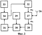
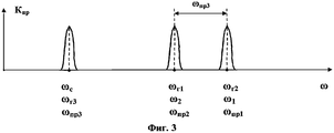
Система, реализующая предлагаемый способ, содержит два объекта. Структурная схема первого объекта (блока запроса) представлена на фиг.1. Структурная схема второго объекта (ретранслятора) представлена на фиг.2. Частотная диаграмма, иллюстрирующая преобразование сигналов, показана на фиг.3.The system that implements the proposed method contains two objects. The structural diagram of the first object (request block) is presented in figure 1. The structural diagram of the second object (repeater) is presented in figure 2. A frequency diagram illustrating signal conversion is shown in FIG. 3.
Первый объект (блок запроса) содержит последовательно включенные задающий генератор 1, фазовый манипулятор 3, второй вход которого соединен с выходом регистра 2 сдвига, первый смеситель 5, второй вход которого соединен с выходом первого гетеродина 4, усилитель 6 первой промежуточной частоты, первый усилитель 7 мощности, первый дуплексер 8, вход-выход которого связан с первой приемопередающей антенной 9, второй усилитель 10 мощности, второй смеситель 12, второй вход которого соединен с выходом второго гетеродина 11, усилитель 13 третьей промежуточной частоты, удвоитель 14 фазы, делитель 15 фазы на два, первый узкополосный фильтр 16, четвертый смеситель 17, второй вход которого соединен с выходом задающего генератора 1, второй узкополосный фильтр 18 и измеритель 19 частоты Доплера, последовательно подключенные к выходу усилителя 13 третьей промежуточной частоты, перемножитель 21, фильтр 22 нижних частот, экстремальный регулятор 23 и блок 24 регулируемой задержки, второй вход которого соединен с выходом фазового манипулятора 3, первый выход соединен со вторым входом перемножителя 21, а второй выход подключен к индикатору 25 дальности. Перемножитель 21, фильтр 22 нижних частот, экстремальный регулятор 23 и блок 24 регулируемой задержки образуют коррелятор 20.The first object (request block) contains a serially connected
К выходу усилителя 13 третьей промежуточной частоты последовательно подключены второй перемножитель 35, второй вход которого соединен с первым выходом блока 24 регулируемой задержки, полосовой фильтр 36, третий перемножитель 37, второй вход которого соединен с выходом второго узкополосного фильтра 18, второй фильтр 38 нижних частот и блок 39 регистрации.To the output of the
Второй объект (ретранслятор) содержит последовательно включенные четвертый усилитель 32 мощности, второй дуплексер 27, вход-выход которого связан с второй приемопередающей антенной 26, третий усилитель 28 мощности, третий смеситель 30, второй вход которого соединен с выходом третьего гетеродина 29, усилитель 31 второй промежуточной частоты и второй фазовый манипулятор 34, второй вход которого соединен с выходом генератора 33 модулирующего кода, а выход подключен к входу четвертого усилителя 32 мощности. Каждый объект снабжен блоком запроса и ретранслятором. Один или оба объекта могут быть подвижными.The second object (repeater) contains in series a
Предлагаемый способ реализуется системой, которая работает следующим образом.The proposed method is implemented by a system that operates as follows.
На первом объекте с помощью задающего генератора 1 формируется высокочастотное колебание:At the first object using a
Uc(t)=Vc·cos(ωс·t+φс), 0≤t≤Tc,U c (t) = V c cos (ω s t + φ s ), 0≤t≤T c ,
где Vc, ωс, φс, Tс - амплитуда, несущая частота, начальная фаза и длительность высокочастотного колебания, которое поступает на первый вход фазового манипулятора 3. На второй вход последнего подается псевдослучайная последовательность (ПСП) M(t) максимальной длительности с выхода регистра 2 сдвига, охваченного логической обратной связью. Обратная связь осуществляется путем сложения по модулю двух выходных напряжений двух или более каскадов и подачи результирующего напряжения на вход первого каскада. Период повторения (длительность) такой кодовой последовательности:where V c , ω s , φ s , T s is the amplitude, carrier frequency, initial phase and duration of the high-frequency oscillation, which is fed to the first input of the
m=2n-1,m = 2 n -1,
где n - число каскадов регистра сдвига.where n is the number of stages of the shift register.
На выходе фазового манипулятора 3 образуется сложный сигнал с фазовой манипуляцией (ФМн):The output of the
U'c(t)=Vc·cos[ωс·t+φк(t)+φc], 0≤t≤Tc,U ' c (t) = V c · cos [ω s · t + φ k (t) + φ c ], 0≤t≤T c ,
где φк(t)={0,π} - манипулируемая составляющая фазы, отображающая закон фазовой манипуляции в соответствии с псевдослучайной последовательностью M(t), причем φк(t)=const при k·τэ<t<(k+1)·τэ и может изменяться скачком при t=k·τэ, т.е. на границах между элементарными посылками (k=1,2,…N);where φ к (t) = {0, π} is the manipulated phase component that displays the phase manipulation law in accordance with the pseudo-random sequence M (t), and φ к (t) = const for k · τ е <t <(k + 1) · τ e and can change abruptly at t = k · τ e , i.e. at the borders between elementary premises (k = 1,2, ... N);
τэ, N - длительность и количество элементарных посылок, из которых составлен сигнал длительностью Тс(Тс=τ3·N).τ e , N is the duration and number of chips that make up a signal of duration T s (T s = τ 3 · N).
Этот сигнал поступает на первый вход первого смесителя 5, на второй вход которого подается напряжение первого гетеродина 4:This signal is fed to the first input of the
Uг1(t)=Vг1·cos(ωг1·t+φг1).U g1 (t) = V g1 · cos (ω g1 · t + φ g1 ).
На выходе смесителя 5 образуются напряжения комбинационных частот. Усилителем 6 выделяется напряжение первой промежуточной (суммарной) частоты:At the output of the
Uпр1(t)=Vпр1·cos[ωпр1·t+φк(t)+φпр1], 0≤t≤Tc,U CR1 (t) = V CR1 · cos [ω CR1 · t + φ k (t) + φ CR1 ], 0≤t≤T c ,
где Vпр1=1/2K1·Vc·Vг1;where V pr1 = 1/2 K 1 · V c · V r1;
K1 - коэффициент передачи смесителя;K 1 - gear ratio of the mixer;
ωпр1=ωс+ωг1=ω1 - первая промежуточная (суммарная) частота;ω pr1 = ω s + ω g1 = ω 1 - the first intermediate (total) frequency;
φпр1=φc+φг1,φ pr1 = φ c + φ g1 ,
которое после усиления в первом усилителе 7 мощности через дуплексер 8 поступает в приемопередающую антенну 9, излучается ею в эфир на частоте ω1, улавливается приемопередающей антенной 26 второго объекта и через дуплексер 27 и усилитель 28 мощности поступает на первый вход третьего смесителя 30, на второй вход которого подается напряжение третьего гетеродина 29:which after amplification in the
Uг3(t)=Vг3·cos(ωг3·t+φг3).U g3 (t) = V g3 · cos (ω g3 · t + φ g3 ).
На выходе смесителя 30 образуются напряжения комбинационных частот. Усилителем 31 выделяется напряжение второй промежуточной частоты:At the output of the
Uпр2(t)=Vпр2·cos[ωпр2·t+φк(t)+φпр2], 0≤t≤Tc,U CR2 (t) = V CR2 · cos [ω CR2 · t + φ k (t) + φ CR2 ], 0≤t≤T c ,
где Vпр2=1/2K1·Vпр1·Vг3; np2 where V = 1/2 K 1 · V · V r3 pr1;
ωпр2=ωпр1-ωг3=ω2 - вторая промежуточная (разностная) частота; np2 ω = ω -ω z3 pr1 = ω 2 - second intermediate (difference) frequency;
φпр2=φпр1-φг3, WP2 cp = φ -φ pr1 r3
которое поступает на первый вход второго фазового манипулятора 34, а на второй вход фазового манипулятора 34 подается модулирующий код M1(t) с выхода генератора 33 модулирующего кода. Модулирующий код M1(t) является идентификационным номером объекта. На выходе фазового манипулятора 34 формируется сложный сигнал с двойной фазовой манипуляцией:which is supplied to the first input of the
U'пр2(t)=Vпр2·cos[ωпр2·t+φк(t)+φк1(t)+φпр2], 0≤t≤Tc,U ' CR2 (t) = V CR2 · cos [ω CR2 · t + φ k (t) + φ K1 (t) + φ CR2 ], 0≤t≤T c ,
где φк(t)={0,π} - манипулируемая составляющая фазы, отображающая закон фазовой манипуляции в соответствии с модулирующим кодом M(t), который после усиления в четвертом усилителе 32 мощности через дуплексер 27 поступает в приемопередающую антенну 26 и излучается ею в эфир на частотах ω2, улавливается приемопередающей антенной 9 первого объекта и через дуплексер 8 и усилитель 10 мощности поступает на первый вход второго смесителя 12, на второй вход которого подается напряжение второго гетеродина 11:where φ к (t) = {0, π} is the phase manipulated component that displays the phase manipulation law in accordance with the modulating code M (t), which, after amplification in the
Uг2(t)=Vг2·cos(ωг2·t+φг2).U g2 (t) = V g2 · cos (ω g2 · t + φ g2 ).
На выходе смесителя 12 образуются напряжения комбинационных частот. Усилителем 13 выделяется напряжение третьей промежуточной (разностной) частоты:At the output of the
Uпр3(t)=Vпр3·cos[(ωпр3·±Ωд)(t-τ3)-φk(t-τ3)-φk1(t-τ3/2)+φпр3], 0≤t≤Tc,U pr3 (t) = V pr3 · cos [(ω pr3 · ± Ω d ) (t-τ 3 ) -φ k (t-τ 3 ) -φ k1 (t-τ 3/2 ) + φ pr3 ], 0≤t≤T c ,
где Vпр3=1/2K1·Vпр2·Vг2; PR3 where V = 1/2 K 1 · V · V r2 np2;
ωпр3=ωг2-ωпр2=ωc - третья промежуточная (разностная) частота; PR3 ω = ω r2 np2 ω = ω c - third intermediate (difference) frequency;
φпр3=φг2-φпр2; PR3 φ = φ r2 np2 -φ;
τ3=2R/C - время запаздывания ретранслированного сигнала относительно запросного;τ 3 = 2R / C is the delay time of the relay signal relative to the request;
R - расстояние между объектами;R is the distance between the objects;
C - скорость распространения радиоволн;C is the propagation velocity of radio waves;
±Ωд - доплеровское смещение частоты,± Ω d - Doppler frequency shift,
которое поступает на вход удвоителя 14 фазы. В качестве последнего может использоваться перемножитель, на два входа которого подается одно и то же напряжение.which is fed to the input of the
На выходе удвоителя 14 фазы образуется гармоническое колебание:At the output of the
U2(t)=V2·cos[2(ωпр3±Ωд)(t-τ3)+2φпр3], 0≤t≤Tc,U 2 (t) = V 2 · cos [2 (ω CR 3 ± Ω d ) (t-τ 3 ) + 2φ CR 3 ], 0≤t≤T c ,
где V2=1/2K2·V2 пр3;wherein V 2 = 1/2 K 2 · V 2 PR3;
K2 - коэффициент передачи перемножителя,K 2 - transfer coefficient of the multiplier,
в котором фазовая манипуляция уже отсутствует, так как 2φк(t-τ3)={0, 2π},in which phase manipulation is already absent, since 2φ to (t-τ 3 ) = {0, 2π},
2φк1(t-τ3/2)={0,2π}.2φ k1 (t-τ 3/2 ) = {0.2π}.
Это колебание поступает на вход делителя 15 фазы на два, на выходе которого образуется гармоническое колебание:This oscillation enters the input of the
U3(t)=V3·cos[(ωпр3±Ωд)(t-τ3)+φпр3],U 3 (t) = V 3 · cos [(ω CR 3 ± Ω d ) (t-τ 3 ) + φ CR 3 ],
которое выделяется узкополосным фильтром 16 и поступает на первый вход четвертого смесителя 17. На выходе смесителя 17 образуются напряжения комбинационных частот. Узкополосным фильтром 18 выделяется напряжение доплеровской частоты:which is allocated by a narrow-
U4(t)=V4·cos(±Ωд·t+φ4), 0≤t≤Tc,U 4 (t) = V 4 · cos (± Ω d · t + φ 4 ), 0≤t≤T c ,
где V4=1/2K1·Vc·V3; 4 where V = 1/2 K 1 · V c · V 3;
φ4=φс-φпр3-ωпр3·τ3,φ 4 = φ s -φ pr3 -ω pr3 · τ 3 ,
которое поступает на вход измерителя 19 доплеровской частоты, который обеспечивает измерение доплеровской частоты ±Ωд. Причем величина и знак доплеровской частоты определяют величину и направление радиальной скорости.which is fed to the input of the
Одновременно напряжение третьей промежуточной частоты Uпр3(t) с выхода усилителя 13 поступает на вход первого перемножителя 21, на второй вход которого подается сложный ФМн-сигнал U'1(t) с выхода фазового манипулятора 3 через блок 24 регулируемой задержки. Полученное на выходе перемножителя 21 напряжение пропускается через фильтр 22 нижних частот, на выходе которого формируется корреляционная функция R(τ). Экстремальный регулятор 23, предназначенный для поддержания максимального значения корреляционной функции R(τ) и подключенный к выходу фильтра 22 нижних частот, воздействует на управляющий вход блока 24 регулируемой задержки и поддерживает вводимую им задержку τ, равной τ3·(τ=τ3), что соответствует максимальному значению корреляционной функции R(τ). Указатель 25 дальности, связанный со шкалой блока 24 регулируемой задержки, позволяет непосредственно считывать измеренное значение расстояния R между объектами:At the same time, the voltage of the third intermediate frequency U pr3 (t) from the output of the
R=с·τ3/2.R = c · τ 3/2.
Следовательно, задача измерения дальности (расстояния) R сводится к измерению временной задержки τ3 ретранслированного сигнала относительно запросного.Therefore, the task of measuring the range (distance) R is reduced to measuring the time delay τ 3 of the relay signal relative to the request.
Одновременно напряжение Uпр3(t) третьей промежуточной частоты с выхода усилителя 13 поступает на первый вход второго перемножителя 35, на второй вход которого подается напряжение:At the same time, the voltage U CR3 (t) of the third intermediate frequency from the output of the
U5(t)=Vc·cos[ωc(t-τ3)+φк(t-τ3)+φс],U 5 (t) = V c · cos [ω c (t-τ 3 ) + φ к (t-τ 3 ) + φ с ],
с первого выхода блока 24 регулируемой задержки. На выходе перемножителя 35 образуется напряжение:from the first output of the
U6(t)=V6·cos[±Ω(t-τ3)+φк1(t-τ3/2)+φ4], 0≤t≤Tc,U 6 (t) = V 6 · cos [± Ω (t-τ 3 ) + φ к1 (t-τ 3/2 ) + φ 4 ], 0≤t≤T c ,
где U6=1/2K2·Vпр3·Vс,where U 6 = 1 / K 2 · V 2 · V with PR3,
которое представляет собой ФМн-сигнал на доплеровской частоте, выделяется полосовым фильтром 36 и поступает на первый вход перемножителя 37. На второй ход последнего подается напряжение U4(t) с выхода узкополосного фильтра 18. На выходе перемножителя 37 образуется низкочастотное напряжение:which is a QPSK signal at the Doppler frequency, is allocated by a band-
Uн(t)=Vн·cosφк1(t-τ3/2)+φ4], 0≤t≤Tc,U n (t) = V n · cosφ to 1 (t-τ 3/2 ) + φ 4 ], 0≤t≤T c ,
где Vн=1/2K2·V4·V6, n where V = 1/2 K 4 · V 2 · V 6,
пропорциональное идентификационному номеру объекта, которое выделяется фильтром 38 нижних частот и регистрируется блоком 39 регистрации.proportional to the identification number of the object, which is allocated by the low-
Таким образом, предлагаемые способ и система по сравнению с прототипами обеспечивают определение идентификационных номеров взаимодействующих объектов, что повышает эффективность их взаимодействия.Thus, the proposed method and system in comparison with prototypes provide the identification of the identification numbers of interacting objects, which increases the efficiency of their interaction.
Тем самым функциональные возможности способа и системы расширены.Thus, the functionality of the method and system is expanded.
Claims (1)
Priority Applications (1)
| Application Number | Priority Date | Filing Date | Title |
|---|---|---|---|
| RU2009134883/09A RU2429503C2 (en) | 2009-09-09 | 2009-09-09 | Inquiry method of measurement of radial velocity |
Applications Claiming Priority (1)
| Application Number | Priority Date | Filing Date | Title |
|---|---|---|---|
| RU2009134883/09A RU2429503C2 (en) | 2009-09-09 | 2009-09-09 | Inquiry method of measurement of radial velocity |
Publications (2)
| Publication Number | Publication Date |
|---|---|
| RU2009134883A RU2009134883A (en) | 2011-03-20 |
| RU2429503C2 true RU2429503C2 (en) | 2011-09-20 |
Family
ID=44053490
Family Applications (1)
| Application Number | Title | Priority Date | Filing Date |
|---|---|---|---|
| RU2009134883/09A RU2429503C2 (en) | 2009-09-09 | 2009-09-09 | Inquiry method of measurement of radial velocity |
Country Status (1)
| Country | Link |
|---|---|
| RU (1) | RU2429503C2 (en) |
Cited By (2)
| Publication number | Priority date | Publication date | Assignee | Title |
|---|---|---|---|---|
| RU2518174C2 (en) * | 2012-07-02 | 2014-06-10 | Федеральное государственное бюджетное учреждение науки Институт прикладной астрономии Российской академии наук | Query-based method of measuring radial velocity and position of glonass global navigation system satellite and system for realising said method |
| RU2529867C2 (en) * | 2013-01-10 | 2014-10-10 | Федеральное государственное бюджетное учреждение "Арктический и антарктический научно-исследовательский институт" | Method of controlling ship movement |
Citations (9)
| Publication number | Priority date | Publication date | Assignee | Title |
|---|---|---|---|---|
| US5223839A (en) * | 1966-06-23 | 1993-06-29 | The United States Of America As Represented By The Secretary Of The Army | Radar identification |
| US5745575A (en) * | 1996-05-20 | 1998-04-28 | The United States Of America As Represented By The Secretary Of The Army | Identification-friend-or-foe (IFF) system using variable codes |
| RU2138062C1 (en) * | 1992-06-30 | 1999-09-20 | Томсон-ЦСФ | Method and device for filtration of responses of radar responders |
| US5973613A (en) * | 1990-06-15 | 1999-10-26 | Raytheon Company | Personal messaging system and method |
| RU2245596C1 (en) * | 2003-07-15 | 2005-01-27 | Федеральное государственное унитарное предприятие "Научно-исследовательский и проектно-технологический институт электроугольных изделий" | Method for producing composition for electrical machine brushes |
| RU2278047C1 (en) * | 2004-12-15 | 2006-06-20 | Виктор Иванович Дикарев | Method of and device for combined radio communication and radio navigation for use in railway transport |
| RU2278048C1 (en) * | 2004-11-05 | 2006-06-20 | Виктор Иванович Дикарев | Method of and device for combined radio communication and radio navigation for use in railway transport |
| RU2297045C1 (en) * | 2005-08-17 | 2007-04-10 | Виктор Иванович Дикарев | Transport vehicle identification system |
| RU2309431C1 (en) * | 2006-02-16 | 2007-10-27 | Вячеслав Адамович Заренков | Method and device for measuring radial velocity |
-
2009
- 2009-09-09 RU RU2009134883/09A patent/RU2429503C2/en not_active IP Right Cessation
Patent Citations (9)
| Publication number | Priority date | Publication date | Assignee | Title |
|---|---|---|---|---|
| US5223839A (en) * | 1966-06-23 | 1993-06-29 | The United States Of America As Represented By The Secretary Of The Army | Radar identification |
| US5973613A (en) * | 1990-06-15 | 1999-10-26 | Raytheon Company | Personal messaging system and method |
| RU2138062C1 (en) * | 1992-06-30 | 1999-09-20 | Томсон-ЦСФ | Method and device for filtration of responses of radar responders |
| US5745575A (en) * | 1996-05-20 | 1998-04-28 | The United States Of America As Represented By The Secretary Of The Army | Identification-friend-or-foe (IFF) system using variable codes |
| RU2245596C1 (en) * | 2003-07-15 | 2005-01-27 | Федеральное государственное унитарное предприятие "Научно-исследовательский и проектно-технологический институт электроугольных изделий" | Method for producing composition for electrical machine brushes |
| RU2278048C1 (en) * | 2004-11-05 | 2006-06-20 | Виктор Иванович Дикарев | Method of and device for combined radio communication and radio navigation for use in railway transport |
| RU2278047C1 (en) * | 2004-12-15 | 2006-06-20 | Виктор Иванович Дикарев | Method of and device for combined radio communication and radio navigation for use in railway transport |
| RU2297045C1 (en) * | 2005-08-17 | 2007-04-10 | Виктор Иванович Дикарев | Transport vehicle identification system |
| RU2309431C1 (en) * | 2006-02-16 | 2007-10-27 | Вячеслав Адамович Заренков | Method and device for measuring radial velocity |
Cited By (2)
| Publication number | Priority date | Publication date | Assignee | Title |
|---|---|---|---|---|
| RU2518174C2 (en) * | 2012-07-02 | 2014-06-10 | Федеральное государственное бюджетное учреждение науки Институт прикладной астрономии Российской академии наук | Query-based method of measuring radial velocity and position of glonass global navigation system satellite and system for realising said method |
| RU2529867C2 (en) * | 2013-01-10 | 2014-10-10 | Федеральное государственное бюджетное учреждение "Арктический и антарктический научно-исследовательский институт" | Method of controlling ship movement |
Also Published As
| Publication number | Publication date |
|---|---|
| RU2009134883A (en) | 2011-03-20 |
Similar Documents
| Publication | Publication Date | Title |
|---|---|---|
| CN114706063A (en) | Method in a radar system, radar system or arrangement of radar systems | |
| EP2788788B1 (en) | Method of determining distance and speed of fmcw radar terminals | |
| RU2429503C2 (en) | Inquiry method of measurement of radial velocity | |
| RU2526401C1 (en) | Method for radar doppler angular measurements of spacecraft and system for realising said method | |
| RU2389040C1 (en) | Query method of measuring radial velocity and system for realising said method | |
| RU2309431C1 (en) | Method and device for measuring radial velocity | |
| RU2518174C2 (en) | Query-based method of measuring radial velocity and position of glonass global navigation system satellite and system for realising said method | |
| RU2660160C1 (en) | Method of determining the motion parameters of an air object by the dynamic radio monitoring system | |
| RU2559813C1 (en) | Method of locating navigation object | |
| Matsuda et al. | DDMA-MIMO observations with the MU radar: Validation by measuring a beam broadening effect | |
| JP2020139776A (en) | FMCW radar device | |
| RU2602274C1 (en) | Radar method and device for remote measurement of full velocity vector of meteorological object | |
| RU2411532C1 (en) | Device for determining distance between aircraft | |
| RU2599984C1 (en) | Differential-range method and ground-space system for measuring spatial coordinates of aircraft based on radio signals of radio radiation of on-board radioelectronic equipment thereof | |
| CN103376448A (en) | Radio system capable of operating in a multiple radio altimeter system | |
| JP7012903B2 (en) | Antenna device and radar device | |
| RU2427853C1 (en) | Phase direction finding method and phase direction finder for implementing said method | |
| RU2560089C1 (en) | Method of passive radio location | |
| RU2309424C1 (en) | Device for measurement of distance between sea vessels | |
| RU2402787C1 (en) | Method of finding vessels in distress | |
| RU2697257C1 (en) | Method of operating a radar system when measuring the speed of an unmanned aerial vehicle of a small class of multi-copter type and its range | |
| RU2535487C1 (en) | Method of measuring radial velocity of object (versions) | |
| RU2605205C2 (en) | Device for distortion of radar image | |
| RU2587471C1 (en) | Method of measuring distance between onboard and ground transceiving stations | |
| RU2302645C1 (en) | Elevation-time doppler method for determining coordinates of emergency object |
Legal Events
| Date | Code | Title | Description |
|---|---|---|---|
| MM4A | The patent is invalid due to non-payment of fees |
Effective date: 20110910 |