RU2425292C1 - Adaptive control system of actuators of heat supply objects of municipal housing economy - Google Patents
Adaptive control system of actuators of heat supply objects of municipal housing economy Download PDFInfo
- Publication number
- RU2425292C1 RU2425292C1 RU2010102109/03A RU2010102109A RU2425292C1 RU 2425292 C1 RU2425292 C1 RU 2425292C1 RU 2010102109/03 A RU2010102109/03 A RU 2010102109/03A RU 2010102109 A RU2010102109 A RU 2010102109A RU 2425292 C1 RU2425292 C1 RU 2425292C1
- Authority
- RU
- Russia
- Prior art keywords
- temperature
- circuit
- consumers
- supply
- input
- Prior art date
Links
Images
Classifications
-
- Y—GENERAL TAGGING OF NEW TECHNOLOGICAL DEVELOPMENTS; GENERAL TAGGING OF CROSS-SECTIONAL TECHNOLOGIES SPANNING OVER SEVERAL SECTIONS OF THE IPC; TECHNICAL SUBJECTS COVERED BY FORMER USPC CROSS-REFERENCE ART COLLECTIONS [XRACs] AND DIGESTS
- Y02—TECHNOLOGIES OR APPLICATIONS FOR MITIGATION OR ADAPTATION AGAINST CLIMATE CHANGE
- Y02B—CLIMATE CHANGE MITIGATION TECHNOLOGIES RELATED TO BUILDINGS, e.g. HOUSING, HOUSE APPLIANCES OR RELATED END-USER APPLICATIONS
- Y02B30/00—Energy efficient heating, ventilation or air conditioning [HVAC]
- Y02B30/70—Efficient control or regulation technologies, e.g. for control of refrigerant flow, motor or heating
Abstract
Description
Изобретение относится к системам теплоснабжения городов и других населенных пунктов и может быть использовано для автоматического учета и регулирования расхода тепла в системах теплоснабжения.The invention relates to heat supply systems of cities and other settlements and can be used for automatic metering and regulation of heat consumption in heat supply systems.
Известна автоматизированная система для измерения и учета расхода теплоносителя и тепла в системах теплоснабжения (Пат. РФ №2144162, МПК 7 F24D 19/10. Автоматизированная система для измерения и учета расхода теплоносителя и тепла в системах теплоснабжения, заявл. 16.07.96; опубл. 10.01.2000. Бюл. №1).A well-known automated system for measuring and accounting for the flow of coolant and heat in heating systems (Pat. RF №2144162, IPC 7 F24D 19/10. Automated system for measuring and accounting for the flow of coolant and heat in heating systems, decl. 16.07.96; publ. January 10, 2000, Bull. No. 1).
Недостаток такой системы заключается в том, что не рассматриваются двухконтурные системы отопления с использованием частотных преобразователей для синхронного регулирования подачи теплоносителя в контурах тепловой сети.The disadvantage of this system is that it does not consider dual-circuit heating systems using frequency converters for synchronously regulating the flow of coolant in the circuits of the heating network.
Известны также системы определения расхода жидкости и тепла по параметрам насосной установки (Пат. РФ №2119148, МПК6 G01F 1/34. Способ измерения массового расхода и плотности жидкости, подаваемой центробежным электронасосом, заявл. 05.03.96; опубл. 20.09.1998. Бюл. №26).There are also known systems for determining the flow rate of liquid and heat according to the parameters of the pump installation (Pat. RF No. 2119148, IPC 6
Недостатки таких систем состоят в несогласованной подаче теплоносителя в контурах для обеспечения оптимальной доставки тепловой энергии территориально распределенным потребителям.The disadvantages of such systems are the inconsistent supply of coolant in the circuits to ensure optimal delivery of thermal energy to geographically distributed consumers.
Наиболее близким к изобретению является система автоматического регулирования расхода тепла в тепловой сети при двухконтурной системе отопления (Пат. РФ №2325591, МПК6 F24D 19/10. Способ автоматического регулирования расхода тепла в тепловой сети при двухконтурной системе отопления, заявл. 01.08.2006; опубл. 27.05.2008).Closest to the invention is a system for automatically controlling the flow of heat in a heating network with a dual-circuit heating system (Pat. RF №2325591, IPC 6 F24D 19/10. A method for automatically controlling the flow of heat in a heating network with a dual-circuit heating system, claimed. 01.08.2006; published on May 27, 2008).
Недостатком известного прототипа является низкая эффективность регулирования тепловых потоков по территориально распределенным потребителям тепловой энергии.A disadvantage of the known prototype is the low efficiency of regulation of heat flows in geographically distributed consumers of thermal energy.
Целью изобретения является повышение эффективности регулирования тепловых потоков по территориально распределенным потребителям тепловой энергии путем согласования потоков теплоносителя в контурах для обеспечения оптимальной доставки тепла потребителям.The aim of the invention is to increase the efficiency of regulation of heat flows in geographically distributed consumers of thermal energy by coordinating the flow of coolant in the circuits to ensure optimal heat delivery to consumers.
Поставленная цель достигается тем, что в известное устройство, содержащее первый контур с источником тепла и блоком управления, сетевой насос с выходом на теплообменник, второй контур тепловой сети с циркуляционным насосом и двигателем, управляемым частотным преобразователем, насосы и двигатели, управляемые частотными преобразователями в каждом из N потребителей тепловой энергии, датчики температуры и давления в подающих и обратных трубопроводах первого и второго контуров тепловой сети и в каждом из N потребителей тепловой энергии, дополнительно введены в каждый из N территориально распределенных потребителей тепловой энергии первый и второй блоки сравнения перепадов давлений, задатчик допустимого перепада давлений, блок сравнения перепадов температур, задатчик допустимого перепада температур, задатчик температуры в обратном трубопроводе, блок сравнения температуры в обратном трубопроводе, задатчик допустимого давления в подающем трубопроводе, блок сравнения допустимого давления, ограничитель по давлению, первый, второй и третий масштабирующие усилители потребителей тепловой энергии, сумматор-корректор управляющих сигналов, задатчик потребляемой тепловой энергии, инвертор, приемо-передатчик потребителя тепловой энергии, N-канальный приемо-передатчик, где N - количество территориально распределенных потребителей тепловой энергии, N корректирующих задатчиков потребителей тепловой энергии, N сигнализаторов превышения допустимого перепада давлений в каждом из N потребителей тепловой энергии, сумматор расхода теплоносителя потребителей тепловой энергии, задатчик расхода теплоносителя потребителей тепловой энергии, блок сравнения расхода теплоносителя потребителей тепловой энергии, сумматор температур в подающих и обратных трубопроводах потребителей тепловой энергии, первый, второй и третий делители на N, блок сравнения температур в подающих и обратных трубопроводах, блок сравнения допустимых перепадов температур в обратных трубопроводах, задатчик допустимых перепадов температур в обратных трубопроводах, сумматор давлений в подающих трубопроводах потребителей тепловой энергии, блок сравнения давлений в подающих трубопроводах, задатчик перепада давлений второго контура, блок сравнения давлений второго контура, первый задатчик температур в подающих трубопроводах, второй задатчик температуры в подающем трубопроводе первого контура, первый и второй блоки сравнения температуры в подающем трубопроводе первого контура, первый, второй и третий масштабирующие усилители второго контура, сумматор управляющих сигналов второго контура, блок сравнения частотного преобразователя второго контура, задатчик частотного преобразователя второго контура, причем в каждом из N территориально распределенных потребителей тепловой энергии первый и второй входы первого блока сравнения перепадов давлений присоединены к выходам датчиков давления в подающем и обратном трубопроводах соответственно, первый вход второго блока сравнения перепадов давлений подсоединен к выходу первого блока сравнения перепадов давлений, а второй вход - к выходу задатчика допустимого перепада давлений, входы блока сравнения перепадов температур подсоединены к датчикам температуры в подающих и обратных трубопроводах и задатчику допустимого перепада температур, выход блока сравнения перепадов температур через инвертор и первый масштабирующий усилитель потребителей тепловой энергии подсоединен к первому входу сумматора-корректора управляющих сигналов, первый вход блока сравнения температуры в обратном трубопроводе подсоединен к датчику температуры в обратном трубопроводе потребителей тепловой энергии, а второй - к задатчику температуры в обратном трубопроводе, выход блока сравнения температуры в обратном трубопроводе через третий масштабирующий усилитель подсоединен к третьему входу сумматора-корректора управляющих сигналов, второй вход которого через второй масштабирующий усилитель подсоединен к датчику температуры в обратном трубопроводе потребителей тепловой энергии, четвертый и пятый входы сумматора-корректора управляющих сигналов подсоединены к выходам задатчика потребляемой тепловой энергии и приемопередатчика потребителя тепловой энергии, первый вход блока сравнения допустимого давления подсоединен к датчику давления в подающем трубопроводе потребителей тепловой энергии, второй вход - к выходу задатчика допустимого давления в подающем трубопроводе, а выход - к управляющему входу ограничителя по давлению, выход сумматора-корректора управляющих сигналов подсоединен через ограничитель по давлению, частотный преобразователь и двигатель - к насосам в каждом из N потребителей тепловой энергии, выходы ограничителя по давлению, датчика температуры в обратном трубопроводе, датчиков температуры и давления в подающем трубопроводе и выход второго блока сравнения перепадов давлений подсоединены к первому, второму, третьему и четвертому входам приемопередатчика в каждом из N потребителей тепловой энергии, приемопередатчики в каждом из N потребителей тепловой энергии по каналу связи соединены с N-канальным приемопередатчиком в управлении источником тепловой энергии, к входу которого подсоединены N корректирующих задатчиков потребителей тепловой энергии, первый, второй, третий и четвертый выходы N-канального приемопередатчика в управлении источником тепловой энергии от каждого из N потребителей тепловой энергии подсоединены к N входовым сумматору расхода теплоносителя, сумматору температур в обратных трубопроводах, сумматору давлений и температур в подающих трубопроводах и N сигнализаторов превышения допустимого перепада давлений в каждом из N потребителей тепловой энергии соответственно, первый вход блока сравнения расхода теплоносителя потребителей тепловой энергии подсоединен к выходу сумматора расхода теплоносителя, второй вход - к задатчику расхода теплоносителя потребителей тепловой энергии, а выход через третий масштабирующий усилитель второго контура - к третьему входу сумматора управляющих сигналов второго контура, первый вход блока сравнения температур в обратных трубопроводах подсоединен к датчику температуры в обратном трубопроводе второго контура, второй вход через первый делитель на N - к выходу сумматора температур в обратных трубопроводах, а выход через первый вход блока сравнения допустимых перепадов температур в обратных трубопроводах и второй масштабирующий усилитель второго контура - к второму входу сумматора управляющих сигналов второго контура, второй вход блока сравнения допустимых перепадов температур в обратных трубопроводах подсоединен к задатчику допустимых перепадов температур в обратных трубопроводах, первый вход блока сравнения давлений в подающих трубопроводах подсоединен к датчику давления в подающем трубопроводе второго контура, второй вход через второй делитель на N - к выходу сумматора давлений в подающих трубопроводах, выход через блок сравнения давлений второго контура и первый масштабирующий усилитель второго контура подсоединен к сумматору управляющих сигналов, второй вход блока сравнения давлений второго контура подсоединен к задатчику перепада давлений второго контура, выход сумматора управляющих сигналов подсоединен через блок сравнения частотного преобразователя второго контура, частотный преобразователь и двигатель - к циркуляционному насосу второго контура тепловой сети, второй вход блока сравнения частотного преобразователя второго контура подсоединен к задатчику частотного преобразователя второго контура, первый вход первого блока сравнения температур в подающих трубопроводах через третий делитель на N подсоединен к выходу сумматора температур в подающих трубопроводах, второй вход - к первому задатчику температур в подающих трубопроводах, а выход через первый вход второго блока сравнения температуры в подающем трубопроводе первого контура подсоединен к блоку управления источником тепловой энергии, первый вход первого блока сравнения температуры в подающем трубопроводе первого контура подсоединен к датчику температуры в подающем трубопроводе первого контура, второй вход - к второму задатчику температуры в подающем трубопроводе, а выход - ко второму входу второго блока сравнения температуры в подающем трубопроводе первого контура.This goal is achieved by the fact that in a known device containing a first circuit with a heat source and a control unit, a network pump with access to a heat exchanger, a second circuit of a heat network with a circulation pump and a motor controlled by a frequency converter, pumps and motors controlled by frequency converters in each from N consumers of thermal energy, temperature and pressure sensors in the supply and return pipelines of the first and second circuits of the heating network and in each of N thermal energy consumers, additional The first and second differential pressure comparison units, an allowable differential pressure adjuster, a temperature differential comparison unit, an allowable temperature differential adjuster, a return temperature setpoint, a return temperature comparison unit, an allowable pressure adjuster were introduced into each of the N geographically distributed consumers of thermal energy in the supply line, permissible pressure comparison unit, pressure limiter, first, second and third scaling amplifiers heat energy consumers, adder-corrector of control signals, setpoint of consumed thermal energy, inverter, transceiver of thermal energy consumer, N-channel transceiver, where N is the number of geographically distributed thermal energy consumers, N correcting thermal energy consumers, N signaling devices exceeding the permissible pressure difference in each of N consumers of thermal energy, the adder of the flow of heat carrier consumers of heat energy, the setpoint flow rate of the consumer oil of thermal energy, a unit for comparing the flow rate of the heat carrier of consumers of thermal energy, an adder of temperatures in the supply and return pipelines of consumers of thermal energy, the first, second and third dividers by N, a unit for comparing temperatures in the supply and return pipelines, a unit for comparing permissible temperature differences in the return pipelines, setpoint for permissible temperature differences in the return pipelines, a pressure adder in the supply pipelines of consumers of thermal energy, a unit for comparing the pressures in the supply piping ovodov, a secondary pressure differential pressure controller, a second circuit pressure comparison unit, a first temperature sensor in the supply pipes, a second temperature sensor in the primary pipe supply, the first and second temperature comparison units in the primary pipe, the first, second and third scaling amplifiers of the second circuit, the adder of the control signals of the second circuit, the unit for comparing the frequency converter of the second circuit, the master of the frequency converter of the second circuit, and in a house of N geographically distributed consumers of thermal energy, the first and second inputs of the first differential pressure comparison unit are connected to the outputs of the pressure sensors in the supply and return pipelines, respectively, the first input of the second differential pressure comparison unit is connected to the output of the first differential pressure comparison unit, and the second input to the output of the permissible differential pressure setter, the inputs of the temperature differential comparison unit are connected to temperature sensors in the supply and return pipelines and the setpoint the permissible temperature difference, the output of the temperature difference comparison unit through the inverter and the first scaling amplifier of thermal energy consumers are connected to the first input of the adder-corrector of control signals, the first input of the temperature comparison unit in the return pipe is connected to the temperature sensor in the return pipe of thermal energy consumers, and the second - to the temperature setpoint in the return pipe, the output of the temperature comparison unit in the return pipe through a third scaling force the heater is connected to the third input of the adder-corrector of control signals, the second input of which through the second scaling amplifier is connected to a temperature sensor in the return pipe of heat energy consumers, the fourth and fifth inputs of the adder-corrector of control signals are connected to the outputs of the setpoint of consumed thermal energy and the transceiver of the consumer of thermal energy , the first input of the allowable pressure comparison unit is connected to a pressure sensor in the supply pipe of thermal Energy, the second input is to the output of the allowable pressure regulator in the supply pipe, and the output is to the control input of the pressure limiter, the output of the adder-corrector of the control signals is connected through the pressure limiter, the frequency converter and the motor to the pumps in each of N thermal energy consumers , the outputs of the pressure limiter, temperature sensor in the return pipe, temperature and pressure sensors in the supply pipe and the output of the second differential pressure comparison unit are connected to the first, W rum, the third and fourth inputs of the transceiver in each of the N heat energy consumers, the transceivers in each of the N heat energy consumers are connected via a communication channel to the N-channel transceiver in controlling the heat energy source, to the input of which are N correcting heat energy consumers, the first , the second, third and fourth outputs of the N-channel transceiver in controlling a heat source from each of N heat consumers are connected to N input sums the flow rate of the coolant, the adder of temperatures in the return pipelines, the accumulator of pressures and temperatures in the supply pipelines and N alarms of exceeding the permissible pressure difference in each of the N consumers of heat energy, respectively, the first input of the unit for comparing the flow of heat transfer consumers of heat energy is connected to the output of the adder flow rate the input is to the flow rate controller of the heat carrier of the heat energy consumers, and the output through the third scaling amplifier of the second circuit is to a third the input to the adder of the control signals of the second circuit, the first input of the temperature comparison block in the return pipelines is connected to the temperature sensor in the return pipe of the second circuit, the second input through the first divider by N to the output of the temperature adder in the return pipelines, and the output through the first input of the allowable comparison unit temperature differences in the return pipelines and the second scaling amplifier of the second circuit to the second input of the adder of the control signals of the second circuit, the second input of the comparison unit to of the possible temperature differences in the return pipelines is connected to the setpoint of permissible temperature differences in the return pipelines, the first input of the pressure comparison unit in the supply pipelines is connected to the pressure sensor in the supply pipe of the second circuit, the second input through the second divider to N is to the output of the pressure adder in the supply pipelines, the output through the unit for comparing the pressures of the second circuit and the first scaling amplifier of the second circuit is connected to the adder of the control signals, the second input of the comp the pressure of the second circuit is connected to the differential pressure controller of the second circuit, the output of the control signal adder is connected through the comparison unit of the frequency converter of the second circuit, the frequency converter and the motor are connected to the circulation pump of the second circuit of the heating network, the second input of the comparison unit of the frequency converter of the second circuit is connected to the frequency the converter of the second circuit, the first input of the first block comparing the temperatures in the supply piping through the third divider N is connected to the output of the temperature adder in the supply pipes, the second input to the first temperature setter in the supply pipes, and the output through the first input of the second temperature comparison unit in the supply pipe of the first circuit is connected to the control unit of the heat energy source, the first input of the first temperature comparison unit in the supply pipe of the first circuit is connected to a temperature sensor in the supply pipe of the first circuit, the second input to the second temperature controller in the supply pipe, and output - to the second input of the second unit for comparing the temperature in the supply pipe of the primary circuit.
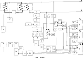
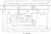
На чертеже представлена структура адаптивной системы управления исполнительными устройствами объектов теплоснабжения жилищно-коммунального хозяйства.The drawing shows the structure of an adaptive control system of executive devices of heat supply facilities of housing and communal services.
Адаптивная система управления исполнительными устройствами объектов теплоснабжения содержит первый контур с источником тепла 1 и блоком управления 2, сетевой насос 3 с выходом на теплообменник 4, второй контур тепловой сети с циркуляционным насосом 5 и двигателем 6, управляемым частотным преобразователем 7, N-канальный приемопередатчик 8 для связи с N потребителями тепловой энергии, N корректирующих задатчиков 9 для N потребителей тепловой энергии, N сигнализаторов превышения допустимого перепада давлений 10 в каждом из N потребителей тепловой энергии, сумматор расхода теплоносителя 11 потребителей тепловой энергии, задатчик расхода теплоносителя 12 потребителей тепловой энергии, блок сравнения расхода теплоносителя 13 потребителей тепловой энергии, сумматор температур 14 в обратных трубопроводах N потребителей тепловой энергии, первый делитель на N 15, блок сравнения температур 16 в обратных трубопроводах, блок сравнения допустимых перепадов температур 17 в обратных трубопроводах, задатчик допустимых перепадов температур 18 в обратных трубопроводах, сумматор давлений в подающих трубопроводах 19 потребителей тепловой энергии, второй делитель на N 20, блок сравнения давлений 21 в подающих трубопроводах, задатчик перепада давлений 22 второго контура, блок сравнения давлений 23 второго контура, сумматор температур в подающих трубопроводах 24 N потребителей тепловой энергии, третий делитель на N 25, блок сравнения температур в подающих трубопроводах 26, первый задатчик температур в подающих трубопроводах 27, второй задатчик температуры в подающем трубопроводе 28 первого контура, первый блок сравнения температуры в подающем трубопроводе первого контура 29, второй блок сравнения температуры в подающем трубопроводе первого контура 30, первый 31, второй 32 и третий 33 масштабирующие усилители второго контура, сумматор управляющих сигналов 34 второго контура, блок сравнения частотного преобразователя 35 второго контура, задатчик частотного преобразователя второго контура 36, датчик температуры в прямом трубопроводе первого контура 37, датчик температуры в обратном трубопроводе 38 второго контура, датчик давления в прямом трубопроводе второго контура 39, N потребителей тепловой энергии 40, первый блок сравнения перепадов давлений 41, второй блок сравнения перепадов давлений 42, задатчик допустимого перепада давлений 43, блок сравнения перепадов температур 44, задатчик допустимого перепада температур 45, задатчик температуры в обратном трубопроводе 46, блок сравнения температуры в обратном трубопроводе 47, задатчик допустимого давления 48 в подающем трубопроводе, блок сравнения допустимого давления 49, ограничитель по давлению 50, первый 51, второй 52 и третий 53 масштабирующие усилители потребителей тепловой энергии, сумматор-корректор управляющих сигналов 54, задатчик потребляемой тепловой энергии 55, инвертор 56, приемо-передатчик 57 потребителя тепловой энергии, насосы 58, двигатель 59, частотный преобразователь 60 потребителя тепловой энергии, датчик температуры в прямом 61 и обратном 62 трубопроводах потребителя тепловой энергии, датчик давления в прямом 63 и обратном 64 трубопроводах потребителя тепловой энергии.The adaptive control system for executive devices of heat supply facilities contains a first circuit with a
Адаптивная система управления исполнительными устройствами объектов теплоснабжения работает следующим образом.Adaptive control system executive devices of heat supply works as follows.
Источник тепла 1 с блоком управления 2 вырабатывает тепловую энергию, которая посредством сетевого насоса 3 через теплообменник 4 передается во второй контур тепловой сети и, затем, с помощью циркуляционного насоса 5 и двигателя 6, управляемого частотным преобразователем 7, передается на N потребителей тепловой энергии 40, территориально удаленных друг от друга и источника тепловой энергии. Передача информационных и управляющих сигналов между источником тепловой энергии, первым и вторым контурами и N территориально распределенными потребителями тепловой энергии 40 производится посредством N-канального приемо-передатчика 8 и N приемопередатчиков 57 N территориально распределенных потребителей тепловой энергии 40.The
На каждом из N территориально распределенных потребителей тепловой энергии 40 установлен насос 58, двигатель 59, частотный преобразователь 60 потребителя тепловой энергии, датчик температуры в прямом 61 и обратном 62 трубопроводах, датчик давления в прямом 63 и обратном 64 трубопроводах потребителя тепловой энергии. Частотный преобразователь 60 потребителя тепловой энергии предназначен для управления скоростью вращения двигателя 59 и, следовательно, величиной расхода потока теплоносителя посредством насоса 58. В свою очередь частотный преобразователь 60 потребителя тепловой энергии через ограничитель по давлению 50 управляется от сумматора-корректора управляющих сигналов 54.A
Сигналы с датчиков давления в прямом 63 и обратном 64 трубопроводах потребителя тепловой энергии сравниваются на первом блоке сравнения перепадов давлений 41, выходной сигнал которого на втором блоке сравнения перепадов давлений 42 сравнивается с допустимым значением, поступающим от задатчика допустимого перепада давлений 43. В результате на выходе второго блока сравнения перепадов давлений 42 формируется сигнал, информирующий о недопустимом перепаде давлений между прямым и обратным трубопроводами потребителя тепловой энергии, который через приемопередатчик 57 передается на соответствующий сигнализатор превышения допустимого перепада давлений 10 в потребителе тепловой энергии, сигнализирующий о возникновении нештатной ситуации в данном потребителе тепловой энергии 40. Также сигнал от датчика давления в прямом 63 трубопроводе подается на блок сравнения допустимого давления 49, где сравнивается с допустимым значением, поступающим от задатчика допустимого давления 48 в подающем трубопроводе, и затем подается на ограничитель по давлению 50 сигнала, поступающего на частотный преобразователь 60. Одновременно сигнал от датчика давления в прямом 63 трубопроводе через приемопередатчик 57 потребителя тепловой энергии и N-канальный приемопередатчик 8 передается на сумматор давлений в подающих трубопроводах 19 потребителей тепловой энергии.The signals from the pressure sensors in the forward 63 and return 64 pipelines of the consumer of thermal energy are compared on the first differential
Сигнал, пропорциональный значению температуры в обратном трубопроводе потребителя тепловой энергии, через датчик температуры в обратном 62 трубопроводе подается на блок сравнения температуры в обратном трубопроводе 47, на второй вход которого подается заданное значение от задатчика температуры в обратном трубопроводе 46. В результате сигнал, пропорциональный отклонению температуры в обратном трубопроводе от заданного значения, с выхода блока сравнения температур в обратном трубопроводе 47 через третий 53 масштабирующий усилитель подается на сумматор-корректор управляющих сигналов 54. Отклонение разности температур в прямом и обратном трубопроводах от заданного значения формируется на выходе блока сравнения перепадов температур 44, на входы которого подаются сигналы от датчиков температуры в прямом 61 и обратном 62 трубопроводах и задатчика допустимого перепада температур 45 в каждом потребителе тепловой энергии. Сигнал с блока сравнения перепадов температур 44 через инвертор 56 и первый 51 масштабирующий усилитель подается на сумматор-корректор управляющих сигналов 54.A signal proportional to the temperature value in the return pipe of the heat energy consumer is fed through a temperature sensor in the
Сигнал, пропорциональный температуре в обратном трубопроводе потребителя тепловой энергии, с датчика температуры в обратном 62 трубопроводе через второй 52 масштабирующий усилитель подается на сумматор-корректор управляющих сигналов 54. Также на сумматор-корректор управляющих сигналов 54 подается управляющий сигнал с задатчика потребляемой тепловой энергии 55 в каждом потребителе тепловой энергии, и через N-канальный приемопередатчик 8 и приемопередатчик 57 подается корректирующий сигнал от соответствующего N корректирующего задатчика 9 для каждого из N потребителей тепловой энергии 40 в отдельности.A signal proportional to the temperature in the return pipe of the consumer of thermal energy from the temperature sensor in the
Сигналы, пропорциональные расходу теплоносителя в каждом потребителе тепловой энергии и температурам в прямом и обратном трубопроводах, от ограничителя по давлению 50, датчиков температуры в прямом 61 и обратном 62 трубопроводах через приемопередатчик 57 потребителя тепловой энергии и N-канальный приемопередатчик 8 передаются на сумматор расхода теплоносителя 11 потребителей тепловой энергии, сумматор температур в подающих трубопроводах 24 потребителей тепловой энергии и сумматор температур 14 в обратных трубопроводах потребителей тепловой энергии соответственно,Signals proportional to the flow rate of the heat carrier in each consumer of thermal energy and temperatures in the forward and return pipelines, from the
Сигналы, пропорциональные расходам теплоносителя в каждом из N потребителей тепловой энергии 40, суммируются на сумматоре расхода теплоносителя 11 потребителей тепловой энергии, затем сумма сравнивается с заданным технологическим значением на блоке сравнения расхода теплоносителя 13, на второй вход которого подается сигнал с задатчика расхода теплоносителя 12 потребителей тепловой энергии. В результате формируется сигнал, пропорциональный отклонению суммы расходов теплоносителя в каждом из N потребителей тепловой энергии 40 от заданного технологического значения, который через третий 33 масштабирующий усилитель второго контура поступает на сумматор управляющих сигналов 34 второго контура.The signals proportional to the flow rates of the heat carrier in each of the N
Сигналы, пропорциональные температурам теплоносителя в обратных трубопроводах в каждом из N потребителей тепловой энергии 40, суммируются на сумматоре температур 14 в обратных трубопроводах, затем полученный сигнал делится на первом делителе на N 15, где N - количество потребителей тепловой энергии, и подается на блок сравнения температур 16 в обратных трубопроводах, на второй вход которого подается сигнал с датчика температуры в обратном трубопроводе 38 второго контура. Сигнал с блока сравнения температур 16 в обратных трубопроводах на блоке сравнения допустимых перепадов температур 17 в обратных трубопроводах сравнивается с заданным значением от задатчика допустимых перепадов температур 18 в обратных трубопроводах и через второй 32 масштабирующий усилитель второго контура поступает на сумматор управляющих сигналов 34 второго контура.The signals proportional to the temperatures of the coolant in the return pipelines in each of the N
Сигналы, пропорциональные давлениям теплоносителя в подающих трубопроводах в каждом из N потребителей тепловой энергии 40, суммируются на сумматоре давлений в подающих трубопроводах 19 потребителей тепловой энергии, затем полученный сигнал делится на втором делителе на N 20 и подается на блок сравнения давлений 21 в подающих трубопроводах, на второй вход которого подается сигнал с датчика давления в прямом трубопроводе второго контура 39. Полученный сигнал на блоке сравнения давлений 23 второго контура сравнивается с заданным технологическим значением, поступающим от задатчика перепада давлений 22 второго контура. В результате на выходе блока сравнения давлений 23 второго контура формируется корректирующий сигнал по давлению, который через первый 31 масштабирующий усилитель второго контура поступает на сумматор управляющих сигналов 34 второго контура.The signals proportional to the coolant pressures in the supply pipelines in each of the N consumers of
Сигналы, пропорциональные температурам теплоносителя в подающих трубопроводах в каждом из N потребителей тепловой энергии 40, суммируются на сумматоре температур в подающих трубопроводах 24 N потребителей тепловой энергии 40, полученный сигнал делится на третьем делителе на N 25 и поступает на блок сравнения температур в подающих трубопроводах 26, где сравнивается с заданным значением, поступающим от первого задатчика температуры в подающих трубопроводах 27. В результате формируется сигнал коррекции температуры в подающем трубопроводе первого контура в зависимости от температуры в подающих трубопроводах N территориально распределенных потребителей тепловой энергии 40, который подается на первый вход второго блока сравнения температуры в подающем трубопроводе первого контура 30. Сигнал, пропорциональный температуре теплоносителя в подающем трубопроводе первого контура, снимается с датчика температуры в прямом трубопроводе первого контура 37, сравнивается с заданным технологическим значением, определяемым вторым задатчиком температуры в подающем трубопроводе 28 первого контура, и подается на второй вход второго блока сравнения температуры в подающем трубопроводе первого контура 30, выходной сигнал которого подается через блок управления 2 на источник тепла 1. В результате производится коррекция работы источника тепла в зависимости от температур теплоносителя в подающих трубопроводах территориально распределенных потребителей тепловой энергии.The signals proportional to the temperatures of the coolant in the supply pipelines in each of the N
На блок сравнения частотного преобразователя 35 второго контура подается управляющий сигнал от задатчика частотного преобразователя второго контура 36 и корректирующий сигнал от сумматора управляющих сигналов 34 второго контура. В результате частотный преобразователь 7 изменяет частоту вращения двигателя 6 циркуляционного насоса 5 относительно заданного технологического значения, корректируя ее с учетом расходов теплоносителя у потребителей тепловой энергии в территориально распределенной тепловой сети, температуры в прямых и обратных трубопроводах второго контура и температур в прямых и обратных трубопроводах непосредственно у потребителей тепла, а также от давлений в прямых и обратных трубопроводах.The control unit from the master of the frequency converter of the
Таким образом, адаптивная система управления исполнительными устройствами объектов теплоснабжения жилищно-коммунального хозяйства обеспечивает повышение эффективности регулирования тепловых потоков по территориально распределенным потребителям тепловой энергии путем коррекции работы системы с учетом расходов теплоносителя, значений температур и давлений в прямых и обратных трубопроводах непосредственно у потребителей тепловой энергии и во втором контуре теплосети, чем достигается согласование потоков теплоносителя в контурах для обеспечения оптимальной доставки тепла потребителям.Thus, the adaptive control system for executive devices of heat supply facilities of the housing and communal services provides an increase in the efficiency of regulation of heat flows across geographically distributed heat energy consumers by correcting the system’s operation taking into account the heat carrier’s flow, temperature and pressure values in the direct and return pipelines directly from heat energy consumers and in the second circuit of the heat supply network, thereby achieving coordination of the coolant flows in the circuits to ensure optimal heat delivery to consumers.
Claims (1)
Priority Applications (1)
| Application Number | Priority Date | Filing Date | Title |
|---|---|---|---|
| RU2010102109/03A RU2425292C1 (en) | 2010-01-26 | 2010-01-26 | Adaptive control system of actuators of heat supply objects of municipal housing economy |
Applications Claiming Priority (1)
| Application Number | Priority Date | Filing Date | Title |
|---|---|---|---|
| RU2010102109/03A RU2425292C1 (en) | 2010-01-26 | 2010-01-26 | Adaptive control system of actuators of heat supply objects of municipal housing economy |
Publications (1)
| Publication Number | Publication Date |
|---|---|
| RU2425292C1 true RU2425292C1 (en) | 2011-07-27 |
Family
ID=44753632
Family Applications (1)
| Application Number | Title | Priority Date | Filing Date |
|---|---|---|---|
| RU2010102109/03A RU2425292C1 (en) | 2010-01-26 | 2010-01-26 | Adaptive control system of actuators of heat supply objects of municipal housing economy |
Country Status (1)
| Country | Link |
|---|---|
| RU (1) | RU2425292C1 (en) |
Cited By (7)
| Publication number | Priority date | Publication date | Assignee | Title |
|---|---|---|---|---|
| RU2484381C1 (en) * | 2012-01-25 | 2013-06-10 | Пильцов Сергей Сергеевич | Continuous monitoring method and system of availability and localisation of section of interpenetration of network heat carrier and heated water in heat exchange equipment of centralised heat supply system |
| RU2514586C1 (en) * | 2013-04-11 | 2014-04-27 | Федеральное государственное бюджетное образовательное учреждение высшего профессионального образования "Тульский государственный университет" (ТулГУ) | Info-measuring and control system for heat production optimisation at heat supply structures |
| RU2520066C1 (en) * | 2013-04-11 | 2014-06-20 | Федеральное государственное бюджетное образовательное учреждение высшего профессионального образования "Тульский государственный университет" (ТулГУ) | Information and measuring system for monitoring of energy saving at production of thermal energy |
| RU2525811C1 (en) * | 2013-04-11 | 2014-08-20 | Федеральное государственное бюджетное образовательное учреждение высшего профессионального образования "Тульский государственный университет" (ТулГУ) | Information-measuring and control system of optimisation of production and consumption of heat energy at distributed facilities of heat supply |
| RU2562782C1 (en) * | 2014-06-18 | 2015-09-10 | ООО "Спецприборкомплектация" | Control system of heat supply facilities |
| RU2580089C1 (en) * | 2014-10-29 | 2016-04-10 | Общество с ограниченной ответственностью Научно-производственное объединение "ЭнергоСистемы" | System for controlling heat supply facilities |
| RU2626293C1 (en) * | 2016-05-17 | 2017-07-25 | Владимир Андреевич Куделькин | Method of monitoring gas compressor unit operation and device for its implementation |
-
2010
- 2010-01-26 RU RU2010102109/03A patent/RU2425292C1/en active IP Right Revival
Cited By (7)
| Publication number | Priority date | Publication date | Assignee | Title |
|---|---|---|---|---|
| RU2484381C1 (en) * | 2012-01-25 | 2013-06-10 | Пильцов Сергей Сергеевич | Continuous monitoring method and system of availability and localisation of section of interpenetration of network heat carrier and heated water in heat exchange equipment of centralised heat supply system |
| RU2514586C1 (en) * | 2013-04-11 | 2014-04-27 | Федеральное государственное бюджетное образовательное учреждение высшего профессионального образования "Тульский государственный университет" (ТулГУ) | Info-measuring and control system for heat production optimisation at heat supply structures |
| RU2520066C1 (en) * | 2013-04-11 | 2014-06-20 | Федеральное государственное бюджетное образовательное учреждение высшего профессионального образования "Тульский государственный университет" (ТулГУ) | Information and measuring system for monitoring of energy saving at production of thermal energy |
| RU2525811C1 (en) * | 2013-04-11 | 2014-08-20 | Федеральное государственное бюджетное образовательное учреждение высшего профессионального образования "Тульский государственный университет" (ТулГУ) | Information-measuring and control system of optimisation of production and consumption of heat energy at distributed facilities of heat supply |
| RU2562782C1 (en) * | 2014-06-18 | 2015-09-10 | ООО "Спецприборкомплектация" | Control system of heat supply facilities |
| RU2580089C1 (en) * | 2014-10-29 | 2016-04-10 | Общество с ограниченной ответственностью Научно-производственное объединение "ЭнергоСистемы" | System for controlling heat supply facilities |
| RU2626293C1 (en) * | 2016-05-17 | 2017-07-25 | Владимир Андреевич Куделькин | Method of monitoring gas compressor unit operation and device for its implementation |
Similar Documents
| Publication | Publication Date | Title |
|---|---|---|
| RU2425292C1 (en) | Adaptive control system of actuators of heat supply objects of municipal housing economy | |
| RU2562782C1 (en) | Control system of heat supply facilities | |
| RU2325591C1 (en) | Automatic regulation of heat flow in heating network for dual-flow heating system | |
| CN105318772A (en) | Method for limiting a supply flow in a heat transfer system | |
| US20160017889A1 (en) | System and flow adaptive sensorless pumping control apparatus for energy saving pumping applications | |
| KR101343863B1 (en) | Variable Flow Heating Control System and Heating Control Method using thereof | |
| CN104769364A (en) | Thermal equilibrium set and control method and control apparatus thereof | |
| EP2587171B1 (en) | Method of controlling a variable delivery pump fitted to a heating system | |
| CN203752889U (en) | Parallel cooling system with heat managing function | |
| JP6033674B2 (en) | Heat supply control device, heat supply system, and heat supply control method | |
| CN103838274B (en) | A kind of multichannel water-cooled temperature controlling system and control method | |
| US11085437B2 (en) | Control method | |
| EP3073205B1 (en) | Method for operating a hydronic heating and/or cooling system, control valve and hydronic heating and/or cooling system | |
| RU2580089C1 (en) | System for controlling heat supply facilities | |
| CA2986606C (en) | Heat exchanger control and diagnostic apparatus | |
| CN104158071A (en) | Constant temperature processing device and method for cooling water under variable working conditions | |
| RU2525811C1 (en) | Information-measuring and control system of optimisation of production and consumption of heat energy at distributed facilities of heat supply | |
| EP2715213B1 (en) | Gas heating system for gas pressure reducing systems and method for obtaining said heating effect | |
| CA2950605C (en) | System and flow adaptive sensorless pumping control apparatus for energy saving pumping applications | |
| EP2541158A2 (en) | Temperature control of a circulation fluid system by thermally optimised operation of a circulation pump | |
| RU2424472C2 (en) | Remote control device of state of thermal plants | |
| RU2520066C1 (en) | Information and measuring system for monitoring of energy saving at production of thermal energy | |
| RU2514586C1 (en) | Info-measuring and control system for heat production optimisation at heat supply structures | |
| RU2016132303A (en) | DEVICE WITH MUCH OF VARIABLE SPEED PUMPS TO ENSURE ENERGY SAVING BY CALCULATING AND COMPENSATING FRICTION LOSSES USING SPEED INDICATOR | |
| CN103419937A (en) | Method for operating an aircraft cooling system and aircraft cooling system |
Legal Events
| Date | Code | Title | Description |
|---|---|---|---|
| MM4A | The patent is invalid due to non-payment of fees |
Effective date: 20120127 |
|
| NF4A | Reinstatement of patent |
Effective date: 20130910 |
|
| QB4A | Licence on use of patent |
Free format text: LICENCE Effective date: 20161125 |