RU2420450C2 - Method of producing synthesis gas in heat exchanger reactor by conversion with steam - Google Patents
Method of producing synthesis gas in heat exchanger reactor by conversion with steam Download PDFInfo
- Publication number
- RU2420450C2 RU2420450C2 RU2006133682/05A RU2006133682A RU2420450C2 RU 2420450 C2 RU2420450 C2 RU 2420450C2 RU 2006133682/05 A RU2006133682/05 A RU 2006133682/05A RU 2006133682 A RU2006133682 A RU 2006133682A RU 2420450 C2 RU2420450 C2 RU 2420450C2
- Authority
- RU
- Russia
- Prior art keywords
- reactor
- heat exchanger
- charge
- water vapor
- stream
- Prior art date
Links
Images

Classifications
-
- C—CHEMISTRY; METALLURGY
- C01—INORGANIC CHEMISTRY
- C01B—NON-METALLIC ELEMENTS; COMPOUNDS THEREOF; METALLOIDS OR COMPOUNDS THEREOF NOT COVERED BY SUBCLASS C01C
- C01B3/00—Hydrogen; Gaseous mixtures containing hydrogen; Separation of hydrogen from mixtures containing it; Purification of hydrogen
- C01B3/02—Production of hydrogen or of gaseous mixtures containing a substantial proportion of hydrogen
- C01B3/32—Production of hydrogen or of gaseous mixtures containing a substantial proportion of hydrogen by reaction of gaseous or liquid organic compounds with gasifying agents, e.g. water, carbon dioxide, air
- C01B3/34—Production of hydrogen or of gaseous mixtures containing a substantial proportion of hydrogen by reaction of gaseous or liquid organic compounds with gasifying agents, e.g. water, carbon dioxide, air by reaction of hydrocarbons with gasifying agents
- C01B3/38—Production of hydrogen or of gaseous mixtures containing a substantial proportion of hydrogen by reaction of gaseous or liquid organic compounds with gasifying agents, e.g. water, carbon dioxide, air by reaction of hydrocarbons with gasifying agents using catalysts
- C01B3/384—Production of hydrogen or of gaseous mixtures containing a substantial proportion of hydrogen by reaction of gaseous or liquid organic compounds with gasifying agents, e.g. water, carbon dioxide, air by reaction of hydrocarbons with gasifying agents using catalysts the catalyst being continuously externally heated
-
- B—PERFORMING OPERATIONS; TRANSPORTING
- B01—PHYSICAL OR CHEMICAL PROCESSES OR APPARATUS IN GENERAL
- B01J—CHEMICAL OR PHYSICAL PROCESSES, e.g. CATALYSIS OR COLLOID CHEMISTRY; THEIR RELEVANT APPARATUS
- B01J8/00—Chemical or physical processes in general, conducted in the presence of fluids and solid particles; Apparatus for such processes
- B01J8/02—Chemical or physical processes in general, conducted in the presence of fluids and solid particles; Apparatus for such processes with stationary particles, e.g. in fixed beds
- B01J8/06—Chemical or physical processes in general, conducted in the presence of fluids and solid particles; Apparatus for such processes with stationary particles, e.g. in fixed beds in tube reactors; the solid particles being arranged in tubes
- B01J8/067—Heating or cooling the reactor
-
- C—CHEMISTRY; METALLURGY
- C01—INORGANIC CHEMISTRY
- C01B—NON-METALLIC ELEMENTS; COMPOUNDS THEREOF; METALLOIDS OR COMPOUNDS THEREOF NOT COVERED BY SUBCLASS C01C
- C01B3/00—Hydrogen; Gaseous mixtures containing hydrogen; Separation of hydrogen from mixtures containing it; Purification of hydrogen
- C01B3/02—Production of hydrogen or of gaseous mixtures containing a substantial proportion of hydrogen
- C01B3/32—Production of hydrogen or of gaseous mixtures containing a substantial proportion of hydrogen by reaction of gaseous or liquid organic compounds with gasifying agents, e.g. water, carbon dioxide, air
- C01B3/34—Production of hydrogen or of gaseous mixtures containing a substantial proportion of hydrogen by reaction of gaseous or liquid organic compounds with gasifying agents, e.g. water, carbon dioxide, air by reaction of hydrocarbons with gasifying agents
- C01B3/38—Production of hydrogen or of gaseous mixtures containing a substantial proportion of hydrogen by reaction of gaseous or liquid organic compounds with gasifying agents, e.g. water, carbon dioxide, air by reaction of hydrocarbons with gasifying agents using catalysts
- C01B3/382—Multi-step processes
-
- C—CHEMISTRY; METALLURGY
- C01—INORGANIC CHEMISTRY
- C01B—NON-METALLIC ELEMENTS; COMPOUNDS THEREOF; METALLOIDS OR COMPOUNDS THEREOF NOT COVERED BY SUBCLASS C01C
- C01B3/00—Hydrogen; Gaseous mixtures containing hydrogen; Separation of hydrogen from mixtures containing it; Purification of hydrogen
- C01B3/02—Production of hydrogen or of gaseous mixtures containing a substantial proportion of hydrogen
- C01B3/32—Production of hydrogen or of gaseous mixtures containing a substantial proportion of hydrogen by reaction of gaseous or liquid organic compounds with gasifying agents, e.g. water, carbon dioxide, air
- C01B3/34—Production of hydrogen or of gaseous mixtures containing a substantial proportion of hydrogen by reaction of gaseous or liquid organic compounds with gasifying agents, e.g. water, carbon dioxide, air by reaction of hydrocarbons with gasifying agents
- C01B3/38—Production of hydrogen or of gaseous mixtures containing a substantial proportion of hydrogen by reaction of gaseous or liquid organic compounds with gasifying agents, e.g. water, carbon dioxide, air by reaction of hydrocarbons with gasifying agents using catalysts
- C01B3/386—Catalytic partial combustion
-
- B—PERFORMING OPERATIONS; TRANSPORTING
- B01—PHYSICAL OR CHEMICAL PROCESSES OR APPARATUS IN GENERAL
- B01J—CHEMICAL OR PHYSICAL PROCESSES, e.g. CATALYSIS OR COLLOID CHEMISTRY; THEIR RELEVANT APPARATUS
- B01J2208/00—Processes carried out in the presence of solid particles; Reactors therefor
- B01J2208/00008—Controlling the process
- B01J2208/00017—Controlling the temperature
- B01J2208/00106—Controlling the temperature by indirect heat exchange
- B01J2208/00168—Controlling the temperature by indirect heat exchange with heat exchange elements outside the bed of solid particles
- B01J2208/00212—Plates; Jackets; Cylinders
- B01J2208/00221—Plates; Jackets; Cylinders comprising baffles for guiding the flow of the heat exchange medium
-
- C—CHEMISTRY; METALLURGY
- C01—INORGANIC CHEMISTRY
- C01B—NON-METALLIC ELEMENTS; COMPOUNDS THEREOF; METALLOIDS OR COMPOUNDS THEREOF NOT COVERED BY SUBCLASS C01C
- C01B2203/00—Integrated processes for the production of hydrogen or synthesis gas
- C01B2203/02—Processes for making hydrogen or synthesis gas
- C01B2203/0205—Processes for making hydrogen or synthesis gas containing a reforming step
- C01B2203/0227—Processes for making hydrogen or synthesis gas containing a reforming step containing a catalytic reforming step
- C01B2203/0233—Processes for making hydrogen or synthesis gas containing a reforming step containing a catalytic reforming step the reforming step being a steam reforming step
-
- C—CHEMISTRY; METALLURGY
- C01—INORGANIC CHEMISTRY
- C01B—NON-METALLIC ELEMENTS; COMPOUNDS THEREOF; METALLOIDS OR COMPOUNDS THEREOF NOT COVERED BY SUBCLASS C01C
- C01B2203/00—Integrated processes for the production of hydrogen or synthesis gas
- C01B2203/02—Processes for making hydrogen or synthesis gas
- C01B2203/025—Processes for making hydrogen or synthesis gas containing a partial oxidation step
- C01B2203/0255—Processes for making hydrogen or synthesis gas containing a partial oxidation step containing a non-catalytic partial oxidation step
-
- C—CHEMISTRY; METALLURGY
- C01—INORGANIC CHEMISTRY
- C01B—NON-METALLIC ELEMENTS; COMPOUNDS THEREOF; METALLOIDS OR COMPOUNDS THEREOF NOT COVERED BY SUBCLASS C01C
- C01B2203/00—Integrated processes for the production of hydrogen or synthesis gas
- C01B2203/02—Processes for making hydrogen or synthesis gas
- C01B2203/025—Processes for making hydrogen or synthesis gas containing a partial oxidation step
- C01B2203/0261—Processes for making hydrogen or synthesis gas containing a partial oxidation step containing a catalytic partial oxidation step [CPO]
-
- C—CHEMISTRY; METALLURGY
- C01—INORGANIC CHEMISTRY
- C01B—NON-METALLIC ELEMENTS; COMPOUNDS THEREOF; METALLOIDS OR COMPOUNDS THEREOF NOT COVERED BY SUBCLASS C01C
- C01B2203/00—Integrated processes for the production of hydrogen or synthesis gas
- C01B2203/02—Processes for making hydrogen or synthesis gas
- C01B2203/0283—Processes for making hydrogen or synthesis gas containing a CO-shift step, i.e. a water gas shift step
-
- C—CHEMISTRY; METALLURGY
- C01—INORGANIC CHEMISTRY
- C01B—NON-METALLIC ELEMENTS; COMPOUNDS THEREOF; METALLOIDS OR COMPOUNDS THEREOF NOT COVERED BY SUBCLASS C01C
- C01B2203/00—Integrated processes for the production of hydrogen or synthesis gas
- C01B2203/04—Integrated processes for the production of hydrogen or synthesis gas containing a purification step for the hydrogen or the synthesis gas
- C01B2203/0415—Purification by absorption in liquids
-
- C—CHEMISTRY; METALLURGY
- C01—INORGANIC CHEMISTRY
- C01B—NON-METALLIC ELEMENTS; COMPOUNDS THEREOF; METALLOIDS OR COMPOUNDS THEREOF NOT COVERED BY SUBCLASS C01C
- C01B2203/00—Integrated processes for the production of hydrogen or synthesis gas
- C01B2203/04—Integrated processes for the production of hydrogen or synthesis gas containing a purification step for the hydrogen or the synthesis gas
- C01B2203/042—Purification by adsorption on solids
- C01B2203/043—Regenerative adsorption process in two or more beds, one for adsorption, the other for regeneration
-
- C—CHEMISTRY; METALLURGY
- C01—INORGANIC CHEMISTRY
- C01B—NON-METALLIC ELEMENTS; COMPOUNDS THEREOF; METALLOIDS OR COMPOUNDS THEREOF NOT COVERED BY SUBCLASS C01C
- C01B2203/00—Integrated processes for the production of hydrogen or synthesis gas
- C01B2203/08—Methods of heating or cooling
- C01B2203/0805—Methods of heating the process for making hydrogen or synthesis gas
- C01B2203/0811—Methods of heating the process for making hydrogen or synthesis gas by combustion of fuel
- C01B2203/0822—Methods of heating the process for making hydrogen or synthesis gas by combustion of fuel the fuel containing hydrogen
-
- C—CHEMISTRY; METALLURGY
- C01—INORGANIC CHEMISTRY
- C01B—NON-METALLIC ELEMENTS; COMPOUNDS THEREOF; METALLOIDS OR COMPOUNDS THEREOF NOT COVERED BY SUBCLASS C01C
- C01B2203/00—Integrated processes for the production of hydrogen or synthesis gas
- C01B2203/08—Methods of heating or cooling
- C01B2203/0805—Methods of heating the process for making hydrogen or synthesis gas
- C01B2203/0838—Methods of heating the process for making hydrogen or synthesis gas by heat exchange with exothermic reactions, other than by combustion of fuel
- C01B2203/0844—Methods of heating the process for making hydrogen or synthesis gas by heat exchange with exothermic reactions, other than by combustion of fuel the non-combustive exothermic reaction being another reforming reaction as defined in groups C01B2203/02 - C01B2203/0294
-
- C—CHEMISTRY; METALLURGY
- C01—INORGANIC CHEMISTRY
- C01B—NON-METALLIC ELEMENTS; COMPOUNDS THEREOF; METALLOIDS OR COMPOUNDS THEREOF NOT COVERED BY SUBCLASS C01C
- C01B2203/00—Integrated processes for the production of hydrogen or synthesis gas
- C01B2203/12—Feeding the process for making hydrogen or synthesis gas
- C01B2203/1205—Composition of the feed
- C01B2203/1211—Organic compounds or organic mixtures used in the process for making hydrogen or synthesis gas
- C01B2203/1235—Hydrocarbons
- C01B2203/1241—Natural gas or methane
-
- C—CHEMISTRY; METALLURGY
- C01—INORGANIC CHEMISTRY
- C01B—NON-METALLIC ELEMENTS; COMPOUNDS THEREOF; METALLOIDS OR COMPOUNDS THEREOF NOT COVERED BY SUBCLASS C01C
- C01B2203/00—Integrated processes for the production of hydrogen or synthesis gas
- C01B2203/12—Feeding the process for making hydrogen or synthesis gas
- C01B2203/1288—Evaporation of one or more of the different feed components
- C01B2203/1294—Evaporation by heat exchange with hot process stream
-
- C—CHEMISTRY; METALLURGY
- C01—INORGANIC CHEMISTRY
- C01B—NON-METALLIC ELEMENTS; COMPOUNDS THEREOF; METALLOIDS OR COMPOUNDS THEREOF NOT COVERED BY SUBCLASS C01C
- C01B2203/00—Integrated processes for the production of hydrogen or synthesis gas
- C01B2203/14—Details of the flowsheet
- C01B2203/141—At least two reforming, decomposition or partial oxidation steps in parallel
-
- C—CHEMISTRY; METALLURGY
- C01—INORGANIC CHEMISTRY
- C01B—NON-METALLIC ELEMENTS; COMPOUNDS THEREOF; METALLOIDS OR COMPOUNDS THEREOF NOT COVERED BY SUBCLASS C01C
- C01B2203/00—Integrated processes for the production of hydrogen or synthesis gas
- C01B2203/14—Details of the flowsheet
- C01B2203/142—At least two reforming, decomposition or partial oxidation steps in series
- C01B2203/143—Three or more reforming, decomposition or partial oxidation steps in series
-
- Y—GENERAL TAGGING OF NEW TECHNOLOGICAL DEVELOPMENTS; GENERAL TAGGING OF CROSS-SECTIONAL TECHNOLOGIES SPANNING OVER SEVERAL SECTIONS OF THE IPC; TECHNICAL SUBJECTS COVERED BY FORMER USPC CROSS-REFERENCE ART COLLECTIONS [XRACs] AND DIGESTS
- Y02—TECHNOLOGIES OR APPLICATIONS FOR MITIGATION OR ADAPTATION AGAINST CLIMATE CHANGE
- Y02E—REDUCTION OF GREENHOUSE GAS [GHG] EMISSIONS, RELATED TO ENERGY GENERATION, TRANSMISSION OR DISTRIBUTION
- Y02E60/00—Enabling technologies; Technologies with a potential or indirect contribution to GHG emissions mitigation
- Y02E60/30—Hydrogen technology
- Y02E60/32—Hydrogen storage
-
- Y—GENERAL TAGGING OF NEW TECHNOLOGICAL DEVELOPMENTS; GENERAL TAGGING OF CROSS-SECTIONAL TECHNOLOGIES SPANNING OVER SEVERAL SECTIONS OF THE IPC; TECHNICAL SUBJECTS COVERED BY FORMER USPC CROSS-REFERENCE ART COLLECTIONS [XRACs] AND DIGESTS
- Y02—TECHNOLOGIES OR APPLICATIONS FOR MITIGATION OR ADAPTATION AGAINST CLIMATE CHANGE
- Y02P—CLIMATE CHANGE MITIGATION TECHNOLOGIES IN THE PRODUCTION OR PROCESSING OF GOODS
- Y02P20/00—Technologies relating to chemical industry
- Y02P20/10—Process efficiency
Abstract
Description
Область изобретенияField of Invention
Объектом изобретения является получение синтез-газа из природного газа или легких углеводородов: метана, этана, пропана, бутана, углеводородов, содержащих менее 10 атомов углерода, а также их смесей.The object of the invention is the production of synthesis gas from natural gas or light hydrocarbons: methane, ethane, propane, butane, hydrocarbons containing less than 10 carbon atoms, as well as mixtures thereof.
Синтез-газ представляет собой смесь, содержащую главным образом (после удаления воды) водород, моноксид углерода и диоксид углерода. Он часто содержит малые количества остаточных углеводородов, обычно метана.Synthesis gas is a mixture containing mainly (after removal of water) hydrogen, carbon monoxide and carbon dioxide. It often contains small amounts of residual hydrocarbons, usually methane.
Синтез-газ может применяться для получения водорода. Его также можно использовать для получения жидких соединений путем химического превращения, например, кислородосодержащих соединений (метанола, простого диметилэфира …) или углеводородов, в частности олефиновых или парафиновых.Synthesis gas can be used to produce hydrogen. It can also be used to produce liquid compounds by chemical conversion, for example, oxygen-containing compounds (methanol, dimethyl ether ...) or hydrocarbons, in particular olefinic or paraffinic.
Уровень техникиState of the art
Известно множество способов получения синтез-газа, в частности способ конверсии с водяным паром (наиболее часто применяемый способ), частичное окисление и автотермический способ.There are many known methods for producing synthesis gas, in particular a steam conversion method (the most commonly used method), partial oxidation, and an autothermal method.
Конверсия с водяным паром (известная под аббревиатурой SMR, которая происходит от английского "steam methane reforming", что означает "конверсия метана с водяным паром") заключается в том, что вводят во взаимодействие загрузку на катализаторе в присутствии водяного пара для получения синтез-газа, который содержит главным образом (кроме водяного пара) смесь оксида углерода и водорода. Эта операция является эндотермической. Обычно ее проводят путем циркуляции загрузки в присутствии водяного пара в трубах, заполненных катализатором (обычно катализатором, содержащим, например, от 6 до 25 мас.% никеля, нанесенного на носитель, содержащий главным образом оксид алюминия или смесь оксида алюминия и одного или нескольких других огнеупорных соединений). Обычно трубы нагревают излучением в трубчатых печах. Наиболее высокие температуры пламени должны находиться на достаточном расстоянии от труб, чтобы не происходило чрезмерного перегрева, и поэтому используемые печи являются крупногабаритными и дорогостоящими.Steam conversion (known under the abbreviation SMR, which is derived from the English “steam methane reforming”, which means “conversion of methane with steam”) is that the charge on the catalyst is reacted in the presence of water vapor to produce synthesis gas which contains mainly (except water vapor) a mixture of carbon monoxide and hydrogen. This operation is endothermic. Usually it is carried out by circulating the charge in the presence of water vapor in pipes filled with a catalyst (usually a catalyst containing, for example, from 6 to 25 wt.% Nickel deposited on a support containing mainly aluminum oxide or a mixture of aluminum oxide and one or more others refractory compounds). Typically, pipes are heated by radiation in tube furnaces. The highest flame temperatures should be located at a sufficient distance from the pipes so that excessive overheating does not occur, and therefore the furnaces used are large and expensive.
Уже предлагалось проводить конверсию с водяным паром в реакторе-теплообменнике (это означает, что тепло передается главным образом путем конвекции, а не путем излучения, как в печи), при этом реакционную среду подвергают непрямому нагреву дымовыми газами при очень высокой температуре.It has already been proposed to carry out steam conversion in a heat exchanger reactor (this means that heat is transferred mainly by convection, and not by radiation, as in a furnace), while the reaction medium is subjected to indirect heating by flue gases at a very high temperature.
Использование высокотемпературных дымовых газов в теплообменнике оказалось, тем не менее, трудным.The use of high temperature flue gases in a heat exchanger was, however, difficult.
Частичное окисление (известное под аббревиатурой POX, которая происходит от английского "partial oxydation", что означает частичное окисление) заключается в образовании путем горения в условиях стехиометрического недостатка высокотемпературной смеси, обычно от 1000 до 1600°С, углеводородов и воздуха или кислорода для окисления углеводородов и получения синтез-газа. В этом способе используют значительные количества кислорода, если нельзя использовать воздух (если нужно получить синтез-газ без азота).Partial oxidation (known by the acronym POX, which is derived from the English "partial oxydation", which means partial oxidation) consists in the formation, by burning under stoichiometric deficiency of a high-temperature mixture, usually from 1000 to 1600 ° C, of hydrocarbons and air or oxygen for the oxidation of hydrocarbons and producing synthesis gas. Significant amounts of oxygen are used in this method if air cannot be used (if synthesis gas without nitrogen is to be obtained).
При автотермическом способе проводят частичное окисление, непосредственно после которого осуществляют каталитическую конверсию с водяным паром в адиабатическом режиме при высокой температуре, например в интервале температур на выходе от 900 до 1000°С. Этот способ представляет собой последовательную комбинацию двух предыдущих способов. Он потребляет меньше кислорода, чем способ РОХ, но требует наличия каталитического слоя.In the autothermal method, partial oxidation is carried out, immediately after which the catalytic conversion with water vapor is carried out in adiabatic mode at high temperature, for example, in the outlet temperature range from 900 to 1000 ° C. This method is a sequential combination of the two previous methods. It consumes less oxygen than the POX method, but requires a catalytic layer.
Задача настоящего изобретения заключается в получении синтез-газа из легких углеводородов в гораздо более компактной установке, чем традиционная установка для конверсии с водяным паром (содержащая печь), обычно со значительно меньшим потреблением кислорода, чем в способах РОХ и автотермическом, даже совсем без кислорода, и с ограничением используемых средств горения. Таким образом, способ согласно изобретению является очень эффективным с энергетической точки зрения, при этом используется установка меньших размеров и стоимость является ограниченной.An object of the present invention is to produce synthesis gas from light hydrocarbons in a much more compact unit than a conventional steam conversion plant (containing a furnace), usually with significantly lower oxygen consumption than in POC and autothermal methods, even without oxygen at all, and with the restriction of the combustion media used. Thus, the method according to the invention is very energy efficient, using a smaller installation and the cost is limited.
Изобретение позволяет также понизить самые высокие температуры, сохраняя энергетическую эффективность на высоком уровне. Это позволяет повысить надежность и продолжительность срока службы установки.The invention also allows to lower the highest temperatures, while maintaining energy efficiency at a high level. This improves the reliability and durability of the installation.
Краткое описание изобретенияSUMMARY OF THE INVENTION
Для достижения указанных задач в способе согласно изобретению используют преимущественно текучий теплоноситель HF для осуществления теплопередачи, необходимой для эндотермических реакций конверсии с водяным паром.To achieve these objectives, the method according to the invention mainly uses a fluid heat carrier HF to carry out the heat transfer necessary for the endothermic steam reforming reactions.
Один из наиболее важных аспектов этого способа заключается в использовании в реакторе-теплообменнике R, в котором происходит конверсия с водяным паром, текучего теплоносителя HF, полученного путем ступенчатого горения, позволяющего многократно осуществлять передачу тепла реакционной среде конверсии с водяным паром с одним или несколькими промежуточными операциями горения с тем, чтобы поднять температуру указанного текучего теплоносителя HF. Таким образом, благодаря многократным операциям нагрева используют меньший объем газа для передачи данного количества тепла. В результате получают выигрыш в энергетическом плане. К тому же установка является существенно более компактной, чем традиционная установка для проведения конверсии с водяным паром в печи. Многократные операции нагрева (горения) HF позволяют также ограничивать максимальные используемые температуры и, следовательно, продлевать срок службы установки.One of the most important aspects of this method is the use in the reactor heat exchanger R, in which the steam reforming takes place, of a fluid heat carrier HF obtained by step combustion, allowing heat transfer to the reaction medium of steam reforming multiple times with one or more intermediate operations combustion in order to raise the temperature of the specified fluid coolant HF. Thus, due to multiple heating operations, a smaller volume of gas is used to transfer a given amount of heat. As a result, gain in energy terms. In addition, the installation is significantly more compact than the traditional installation for the conversion with steam in the furnace. Multiple heating (burning) operations of HF can also limit the maximum temperatures used and, therefore, extend the life of the installation.
Было также обнаружено в соответствии с отличительным вариантом способа согласно изобретению, что можно осуществлять ступенчатое горение в более компактной и экономичной установке в компактном реакторе-теплообменнике при условии, что на уровне труб для конверсии с водяным паром не будет пламени, высоких температур которого следует избегать, т.к. они могут привести к порче или разрушению этих труб.It was also found in accordance with a distinctive variant of the method according to the invention that it is possible to carry out step-by-step combustion in a more compact and economical installation in a compact heat exchanger reactor, provided that there is no flame at the level of the steam conversion pipes, which should be avoided at high temperatures, because they can lead to damage or destruction of these pipes.
Таким образом, изобретение обеспечивает также осуществление конверсии с водяным паром в реакторе-теплообменнике R путем проведения на уровне текучего теплоносителя реакции горения без пламени внутри камеры реактора-теплообменника R по крайней мере на уровне труб для конверсии с водяным паром.Thus, the invention also provides for the conversion with water vapor in the reactor heat exchanger R by conducting a combustion reaction without flame inside the chamber of the reactor heat exchanger R at the level of the fluid coolant R at least at the level of the steam conversion tubes.
Подробное описание изобретенияDETAILED DESCRIPTION OF THE INVENTION
Указанные ниже обозначения соответствуют тем, которые используют далее для описания прилагаемых чертежей. Далее в тексте выражения «частичное горение» и «частичное окисление» или РОХ используются в одном и том же значении. Горение может означать полное или частичное горение.The following designations correspond to those used further to describe the accompanying drawings. Further in the text the expressions “partial combustion” and “partial oxidation” or POC are used in the same meaning. Burning may mean full or partial burning.
Изобретение относится к способу получения синтез-газа SG из общей загрузки F, содержащей углеводороды и возможно рециркулируемые соединения, при этом F содержит первую загрузку F1, вторую загрузку F2 и третью загрузку F3, в ходе которого:The invention relates to a method for producing SG synthesis gas from a total charge F containing hydrocarbons and possibly recyclable compounds, wherein F comprises a first charge F1, a second charge F2 and a third charge F3, during which:
поток, содержащий первую загрузку F1 с добавлением водяного пара, подвергают конверсии с водяным паром для получения по меньшей мере одной фракции синтез-газа SG в по меньшей мере одном мультитрубчатом реакторе-теплообменнике R, имеющем множество реакционных труб (38), содержащих катализатор конверсии с водяным паром, и паровую камеру, в которой находятся эти трубы;the stream containing the first charge F1 with the addition of water vapor is subjected to steam conversion to obtain at least one fraction of the synthesis gas SG in at least one multitubular reactor-heat exchanger R having a plurality of reaction tubes (38) containing a conversion catalyst with water vapor, and the steam chamber in which these pipes are located;
указанные реакционные трубы (38) нагревают главным образом посредством конвекции путем циркуляции в указанной паровой камере текучего теплоносителя HF снаружи по отношению к трубам, в котором HF содержит по меньшей мере первый поток газа частичного или полного горения второй загрузки F2, который циркулирует в реакторе-теплообменнике R для нагревания реакционных труб, который затем смешивают в по меньшей мере одной дополнительной зоне горения (32, 34, 42, 44) с по меньшей мере частью третьей загрузки F3 и газом, содержащим кислород, чтобы повысить температуру указанного первого потока, затем поток полученной таким образом смеси циркулирует в реакторе-теплообменнике R для дополнительного нагрева реакционных труб (38) до выхода из этого реактора-теплообменника;said reaction tubes (38) are heated mainly by convection by circulating in the said steam chamber the fluid coolant HF externally with respect to the tubes, in which HF contains at least a first partial or total combustion gas stream of a second charge F2 which is circulated in the heat exchanger reactor R for heating the reaction tubes, which are then mixed in at least one additional combustion zone (32, 34, 42, 44) with at least a portion of the third charge F3 and a gas containing oxygen to increase those the temperature of said first stream, then the stream of the mixture thus obtained is circulated in the heat exchanger reactor R to further heat the reaction tubes (38) until it leaves the heat exchanger reactor;
получают синтез-газ SG из потока после конверсии с водяным паром F1 и возможно части или всего HF.receive synthesis gas SG from the stream after conversion with water vapor F1 and possibly part or all of HF.
Загрузки F1, F2 и F3 могут быть разными, газообразными и/или жидкими. Они могут иметь одинаковый или разный состав. Тем не менее, наиболее часто загрузки F1, F2 и F3 представляют собой углеводороды, главным образом, газообразные под давлением 2 МПа и при температуре 20°С. Обычно F1, F2 и F3 имеют одинаковый состав и происходят из природного или очищенного газа или из газообразной смеси, главным образом состоящей из (в молярных %) углеводородов, содержащих менее 5 атомов углерода.Charges F1, F2 and F3 may be different, gaseous and / or liquid. They may have the same or different composition. However, the most common loading of F1, F2 and F3 are hydrocarbons, mainly gaseous at a pressure of 2 MPa and at a temperature of 20 ° C. Typically, F1, F2 and F3 have the same composition and come from natural or purified gas or from a gaseous mixture, mainly consisting of (in molar%) hydrocarbons containing less than 5 carbon atoms.
Согласно изобретению термин "загрузка" означает как углеводородную загрузку, так и поток, рециркулируемый из углеводородной загрузки. Так F2 и/или F3 могут также содержать или состоять из рециркулируемого потока, в частности потока, содержащего фракцию, отделенную ниже, такую как фракция SG, отделенную адсорбцией и десорбцией при балансировке давления для получения водорода (обычно продувочный газ адсорбции, называемый PSA). Таким образом можно, в частности, использовать для F2 и/или F3 продувочный газ, содержащий СО и остаточный метан и в частых случаях СО2. Как вариант, можно использовать для F2 и/или F3 по существу чистый водород, в частности фракцию водорода, полученного при использовании SG для получения водорода.According to the invention, the term “charge” means both a hydrocarbon charge and a stream recycled from the hydrocarbon charge. Thus, F2 and / or F3 may also comprise or consist of a recycle stream, in particular a stream containing a fraction separated below, such as an SG fraction separated by adsorption and desorption under pressure balancing to produce hydrogen (usually an adsorption purge gas called PSA). Thus, it is possible, in particular, to use a purge gas containing CO and residual methane and, in frequent cases, CO 2 , for F2 and / or F3. Alternatively, substantially pure hydrogen can be used for F2 and / or F3, in particular the fraction of hydrogen obtained by using SG to produce hydrogen.
Обычно можно использовать одну, или две, или три, даже от 4 до 8 дополнительных зон горения. Предпочтительно используют от 1 до 4 дополнительные зоны горения и более предпочтительно 2 или 3 дополнительные зоны горения. Такое ступенчатое горение обеспечивает передачу значительного количества тепла путем приращения температуры с промежуточными охлаждениями (теплопередача для конверсии с водяным паром), без достижения чрезвычайно высоких температур, которые могли бы быть получены при горении в одну стадию. И, наоборот, при ограничении максимальной температуры газа горения ступенчатое горение с одной или несколькими промежуточными теплопередачами позволяет передавать значительно большее количество тепла при данном объеме газа горения или идентичное количество тепла при меньшем объеме газа горения.You can usually use one, or two, or three, even from 4 to 8 additional combustion zones. Preferably, 1 to 4 additional combustion zones are used, and more preferably 2 or 3 additional combustion zones. Such stepwise combustion provides the transfer of a significant amount of heat by incrementing the temperature with intermediate cooling (heat transfer for conversion with water vapor), without reaching the extremely high temperatures that could be obtained by burning in one stage. Conversely, by limiting the maximum temperature of the combustion gas, step-by-step combustion with one or more intermediate heat transfer allows you to transfer much more heat for a given volume of combustion gas or an identical amount of heat with a smaller volume of combustion gas.
Эти зоны горения (первоначальная и/или одна или несколько дополнительных) могут быть внутренними и/или внешними по отношению к камере реактора-теплообменника R. Горение может быть частичным или полным с использованием в качестве горючего кислорода или воздуха, или воздуха, обогащенного кислородом.These combustion zones (initial and / or one or several additional) can be internal and / or external with respect to the chamber of the heat exchanger R. The combustion can be partial or complete using oxygen or air or oxygen enriched air as fuel.
Более конкретно в качестве текучего теплоносителя HF можно использовать поток частичного окисления углеводородов кислородом, обычно под давлением от 0,5 до 12 МПа, по существу не содержащий азота и предпочтительно содержащий водяной пар. Эта жидкость HF, находящаяся под высоким давлением и содержащая водород, обладает хорошими свойствами текучего теплоносителя (высокий коэффициент теплообмена).More specifically, a partial oxidation of hydrocarbons with oxygen, usually under a pressure of from 0.5 to 12 MPa, substantially nitrogen-free and preferably containing steam, can be used as the HF fluid. This HF fluid, which is under high pressure and contains hydrogen, has good fluid flow properties (high heat transfer coefficient).
Также в качестве текучего теплоносителя HF часто используют газ полного горения углеводородов на воздухе, обычно под давлением от 0,4 до 4 МПа.Also, the gas of complete combustion of hydrocarbons in air, usually under pressure from 0.4 to 4 MPa, is often used as the HF fluid.
В соответствии с первым вариантом, характерным для изобретения, одна или несколько дополнительных зон горения расположены внутри паровой камеры реактора-теплообменника R. Первичная зона горения может также являться внутренней зоной реактора-теплообменника.According to a first embodiment characteristic of the invention, one or more additional combustion zones are located inside the steam chamber of the heat exchanger reactor R. The primary combustion zone can also be an internal zone of the heat exchanger reactor.
Обычно дополнительная зона горения является зоной, не содержащей реакционных труб и по существу совмещенной с внутренней стенкой камеры реактора-теплообменника R.Typically, the additional combustion zone is a zone that does not contain reaction tubes and is substantially aligned with the inner wall of the chamber of the reactor-heat exchanger R.
В соответствии с этим первым вариантом, характерным для изобретения, очень предпочтительно избегать контакта пламени с реакционными трубами.According to this first embodiment characteristic of the invention, it is very preferable to avoid contact of the flame with the reaction tubes.
В соответствии с первым вариантом горения это можно осуществить путем ограничения присутствия пламени в одной или нескольких зонах горения, которые не содержат реакционных труб, в частности, совмещенных с внутренней стенкой паровой камеры реактора-теплообменника R. Более конкретно можно использовать одну или несколько плоскопламенных или короткопламенных горелок известного типа и/или множество горелок малого размера, пламя которых меньше.In accordance with the first combustion option, this can be done by restricting the presence of flame in one or more combustion zones that do not contain reaction tubes, in particular, combined with the inner wall of the steam chamber of the reactor-heat exchanger R. More specifically, one or more flame or short flame can be used. burners of a known type and / or a plurality of small burners whose flame is smaller.
В соответствии с другим вариантом осуществления горения в точку, расположенную внутри паровой камеры реактора-теплообменника, впрыскивают по меньшей мере часть F3 и газ, содержащий кислород (например, воздух или О2), в условиях турбулентности и/или рециркуляции, достаточных для получения зоны горения в гомогенном режиме в реакторе-теплообменнике R.In accordance with another embodiment of the combustion, at least a part of F3 and a gas containing oxygen (for example, air or O 2 ) are injected into a point located inside the steam chamber of the reactor-heat exchanger under conditions of turbulence and / or recirculation sufficient to obtain a zone homogeneous combustion in the heat exchanger reactor R.
Для получения наиболее возможно гомогенных условий горения можно осуществлять процесс при относительно умеренных температурах (например, с конечной температурой ниже 1200°С, даже 1150°С, например от 1000°С до 1180°С), облегчая гомогенное горение (без пламени). Интервал адекватных для такого режима гомогенного горения условий (концентрации и температуры) можно определить с точностью путем моделирования горения и/или путем опытных испытаний, изменяя рециркуляцию газа и турбулентность. Действительно, гомогенному горению способствует высокая турбулентность смеси реактивов и их рециркуляция. Горение в гомогенном режиме предпочтительно используют в непосредственной близости от труб для конверсии с водяным паром и осуществляют непосредственную передачу тепла от горения трубам. Горение в гомогенном режиме можно таким образом осуществлять на уровне труб для конверсии с водяным паром, т.к. оно не дает высоких температур, которые могут их повредить. Таким образом становится возможным достичь более однородных температур в реакторе-теплообменнике, что позволяет оптимизировать теплопередачу, уменьшить количество дополнительных зон горения и/или ограничить максимальную эффективную локальную температуру текучей среды HF, что является благоприятным с точки зрения продолжительности срока службы оборудования.To obtain the most possible homogeneous combustion conditions, the process can be carried out at relatively moderate temperatures (for example, with a final temperature below 1200 ° C, even 1150 ° C, for example from 1000 ° C to 1180 ° C), facilitating homogeneous combustion (without flame). The range of conditions adequate for such a mode of homogeneous combustion (concentration and temperature) can be determined with accuracy by simulating combustion and / or by experimental tests, changing gas recirculation and turbulence. Indeed, homogeneous combustion contributes to the high turbulence of the mixture of reagents and their recirculation. Combustion in a homogeneous mode is preferably used in the immediate vicinity of the pipes for steam conversion and the heat is transferred directly from the combustion to the pipes. Combustion in a homogeneous mode can thus be carried out at the level of the pipes for conversion with water vapor, because it does not give high temperatures that can damage them. Thus, it becomes possible to achieve more uniform temperatures in the heat exchanger reactor, which allows to optimize heat transfer, reduce the number of additional combustion zones and / or limit the maximum effective local temperature of the fluid HF, which is favorable in terms of the service life of the equipment.
В соответствии с третьим вариантом горения в точку, расположенную внутри паровой камеры реактора-теплообменника, впрыскивают по меньшей мере часть F3 и газ, содержащий кислород, перед зоной каталитического горения в условиях, при которых температура полученной смеси ниже температуры, при которой горение происходит с пламенем.According to a third embodiment of combustion, at least a part of F3 and an oxygen-containing gas are injected into a point located inside the steam chamber of the reactor-heat exchanger in front of the catalytic combustion zone under conditions at which the temperature of the resulting mixture is lower than the temperature at which combustion occurs with a flame .
Каталитическое горение является технологией, хорошо известной в области горения, и может осуществляться с использованием различных катализаторов. Например, можно сослаться на патенты или патентные заявки US 20050081443, US 5980843, US 5405260, EP 0689870 B1, EP 0712661 B1.Catalytic combustion is a technology well known in the field of combustion and can be carried out using various catalysts. For example, you can refer to patents or patent applications US 20050081443, US 5980843, US 5405260, EP 0689870 B1, EP 0712661 B1.
Зоны первичной и конечной температур, обеспечивающие осуществление каталитического горения в оптимальных условиях, можно определить опытным путем для данного катализатора. Предпочтительные первичные температуры смеси (до горения) составляют менее 900°С, часто от 800 до 880°С. Предпочтительные конечные температуры (после горения) ниже 1000°С, часто составляют от 800°С до 980°С. Также можно преимущественно ограничить каталитическое горение в наименее горячей части реактора-теплообменника R. Так, если поток, содержащий первую загрузку F1 с добавление водяного пара, входит с одного торца реактора теплообменника, зона каталитического горения обычно находится в первой половине реактора-теплообменника относительно этого торца.Zones of primary and final temperatures, ensuring the implementation of catalytic combustion under optimal conditions, can be determined empirically for this catalyst. Preferred primary temperatures of the mixture (before burning) are less than 900 ° C, often from 800 to 880 ° C. Preferred final temperatures (after burning) are below 1000 ° C, often from 800 ° C to 980 ° C. It is also possible to preferentially limit catalytic combustion in the least hot part of the heat exchanger reactor R. So, if the stream containing the first charge F1 with the addition of water vapor enters from one end of the heat exchanger reactor, the catalytic combustion zone is usually located in the first half of the heat exchanger reactor .
В соответствии со вторым вариантом осуществления способа по изобретению одна или несколько дополнительных зон горения (42, 44) и/или зона первичного горения могут находиться снаружи от камеры (37) реактора-теплообменника R. В этом варианте размеры менее компактны, но габариты горелок и зон горения являются стандартными.According to a second embodiment of the method according to the invention, one or more additional combustion zones (42, 44) and / or the primary combustion zone may be located outside the chamber (37) of the heat exchanger reactor R. In this embodiment, the dimensions are less compact, but the dimensions of the burners and Combustion zones are standard.
Можно также комбинировать одну или две внешние зоны горения (например, первичную зону) и одну или две или несколько внутренних зон горения.You can also combine one or two external combustion zones (for example, the primary zone) and one or two or more internal combustion zones.
Циркуляцию текучего теплоносителя HF можно осуществлять разными способами.The circulation of the fluid HF can be carried out in various ways.
Наиболее часто поток, содержащий первую загрузку F1 с добавлением водяного пара, циркулирует в реакторе-теплообменнике главным образом в одном направлении, и текучий теплоноситель HF циркулирует по меньшей мере полностью в режиме противотока по отношению к F1 (т.е. или в виде чистого противотока, при этом HF циркулирует параллельно трубам, или локально в виде перекрестного потока, но в целом в виде противотока).Most often, the stream containing the first charge F1 with the addition of water vapor circulates in the reactor-heat exchanger mainly in one direction, and the fluid coolant HF circulates at least completely in countercurrent mode with respect to F1 (i.e., or as a pure countercurrent , while HF circulates parallel to the pipes, or locally in the form of a cross flow, but in general in the form of a counterflow).
Однако прямоточная циркуляция является возможной. В этом случае, если поток, содержащий первую загрузку F1 с добавлением водяного пара, циркулирует в реакторе-теплообменнике главным образом в одном направлении, текучий теплоноситель HF циркулирует по меньшей мере полностью в прямоточном режиме по отношению к F1 (чистый или общий прямоток).However, direct-flow circulation is possible. In this case, if the stream containing the first charge F1 with the addition of water vapor circulates in the reactor-heat exchanger mainly in one direction, the fluid coolant HF circulates at least completely in direct-flow mode with respect to F1 (pure or general forward flow).
Соответствующие величины давления Р1 и Р2 вытекающих потоков после конверсии с водяным паром, обозначаемых SG1, и HF на выходе из реактора-теплообменника обычно являются следующими:The corresponding pressure values P1 and P2 of the effluent after conversion with water vapor, denoted by SG1, and HF at the outlet of the reactor-heat exchanger are usually as follows:
0,8 МПа<Р1<12 МПа, предпочтительно 1,5 МПа<Р1<5 МПа и более предпочтительно 1,8 МПа<Р1<4,5 МПа;0.8 MPa <P1 <12 MPa, preferably 1.5 MPa <P1 <5 MPa, and more preferably 1.8 MPa <P1 <4.5 MPa;
0,4 МПа<Р2<12 МПа, предпочтительно 0,4 МПа<Р2<5 МПа и более предпочтительно 0,8 МПа<Р2<4,5 МПа;0.4 MPa <P2 <12 MPa, preferably 0.4 MPa <P2 <5 MPa, and more preferably 0.8 MPa <P2 <4.5 MPa;
Относительно высокое давление HF обеспечивает более высокие свойства теплопередачи.Relatively high pressure HF provides higher heat transfer properties.
В целом на выходе из реактора-теплообменника R текучий теплоноситель HF обычно при относительно высокой температуре, например порядка 1000°С, передает тепло потоку, содержащему первую загрузку F1 с добавлением водяного пара, для предварительной частичной конверсии с водяным паром загрузки F1 в другом реакторе-теплообменнике, который далее будет обозначен (2b), непосредственно перед входом F1 в главный реактор-теплообменник R. Эту предварительную конверсию с водяным паром обычно проводят способом, подобным основной конверсии с водяным паром, в реакторе-теплообменнике (2b) с реакционными трубами, содержащем катализатор конверсии с водяным паром, и обычно осуществляют при температурах, которые на 100°С-200°С ниже, чем температуры основной конверсии с водяным паром в реакторе-теплообменнике R.In general, at the outlet of the reactor-heat exchanger R, the fluid coolant HF, usually at a relatively high temperature, for example, of the order of 1000 ° C, transfers heat to the stream containing the first charge F1 with the addition of water vapor, for preliminary partial conversion with water vapor of the charge F1 in another reactor the heat exchanger, which will be designated below (2b), immediately before the entrance of F1 to the main reactor-heat exchanger R. This pre-conversion with water vapor is usually carried out in a manner similar to the main conversion with water vapor, in p a reactor-heat exchanger (2b) with reaction tubes containing a steam conversion catalyst, and is usually carried out at temperatures that are 100 ° C-200 ° C lower than the temperatures of the main steam conversion in the heat exchanger reactor R.
На выходе из реактора-теплообменника (2b) текучий теплоноситель HF обычно передает остаточное тепло потоку, содержащему первую загрузку F1 с добавлением водяного пара в реакторе-теплообменнике (2а), расположенном непосредственно перед (2b) по отношению к F1. Таким образом, эффективно используют тепловой потенциал HF, который на выходе из R передает калории при относительно высокой температуре, необходимые для проведения конверсии с водяным паром в (2b), затем калории при относительно низкой температуре, необходимые для предварительного нагрев потока, содержащего первую загрузку F1 с добавлением водяного пара.At the outlet of the heat exchanger reactor (2b), the fluid coolant HF typically transfers the residual heat to the stream containing the first charge F1 with the addition of water vapor in the heat exchanger reactor (2a) located immediately before (2b) with respect to F1. Thus, the thermal potential HF is effectively used, which, at the outlet from R, transfers the calories at relatively high temperature necessary for the steam conversion in (2b), then the calories at relatively low temperature necessary for preheating the stream containing the first charge F1 with the addition of water vapor.
Поток, содержащий первую загрузку F1 с добавлением водяного пара, обычно предварительно нагревают до температуры от 500°С до 740°С и (предпочтительно от 580°С до 700°С) до его ввода в реактор-теплообменник R. Температура потока после конверсии с водяным паром SG1 на выходе из реактора-теплообменника R обычно составляет от 800°С до 950°С (и предпочтительно от 820°С до 900°С), и температура HF на выходе из реактора-теплообменника R обычно составляет от 850°С до 1150°С и предпочтительно от 900 до 1050°С.The stream containing the first charge F1 with the addition of water vapor is usually preheated to a temperature of from 500 ° C to 740 ° C and (preferably from 580 ° C to 700 ° C) before it is introduced into the heat exchanger R. The temperature of the stream after conversion with the steam SG1 at the outlet of the reactor heat exchanger R is usually from 800 ° C to 950 ° C (and preferably from 820 ° C to 900 ° C), and the temperature HF at the outlet of the reactor heat exchanger R is usually from 850 ° C to 1150 ° C. And preferably from 900 to 1050 ° C.
Изобретение также относится к способу получения водорода из синтез-газа, содержащего синтез-газ SG, полученный способом, описанным выше в соответствии с любым из его вариантов.The invention also relates to a method for producing hydrogen from synthesis gas containing SG synthesis gas, obtained by the method described above in accordance with any of its variants.
Горючая часть текучего теплоносителя HF (или F2 и/или F3) может главным образом состоять из по существу чистой водородной фракции, полученной из SG.The combustible portion of the fluid HF (or F2 and / or F3) may mainly consist of a substantially pure hydrogen fraction derived from SG.
F2 и/или F3 могут также содержать продувочный газ, полученный на стадии очистки путем адсорбции PSA (с балансировкой давления) потока, полученного из SG. Это позволяет преимущественно использовать этот продувочный газ.F2 and / or F3 may also contain purge gas obtained in the purification step by adsorption of a PSA (pressure-balanced) stream obtained from SG. This allows the predominant use of this purge gas.
Изобретение можно лучше понять при чтении описания прилагаемых фигур, в котором изобретение описано для случая, когда текучий теплоноситель HF является потоком частичного окисления газообразных углеводородов кислородом.The invention can be better understood by reading the description of the accompanying figures, in which the invention is described for the case when the fluid coolant HF is a stream of partial oxidation of gaseous hydrocarbons with oxygen.
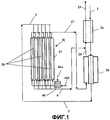
На фиг.1 изображена упрощенная схема осуществления способа согласно изобретению.Figure 1 shows a simplified diagram of the implementation of the method according to the invention.
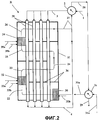
На фиг.2 изображена другая упрощенная схема осуществления способа согласно изобретению, на которой более подробно представлен реактор-теплообменник, содержащий внутренние зоны частичного окисления.Figure 2 shows another simplified diagram of the implementation of the method according to the invention, which presents in more detail a reactor-heat exchanger containing internal zones of partial oxidation.
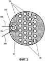
На фиг.3 изображен разрез реактора-теплообменника по фиг.2.Figure 3 shows a section of the reactor-heat exchanger of figure 2.
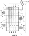
На фиг.4 изображена другая упрощенная схема осуществления способа согласно изобретению, на которой более подробно представлен реактор-теплообменник, содержащий внешние зоны частичного окисления.Figure 4 shows another simplified diagram of the implementation of the method according to the invention, which shows in more detail a reactor-heat exchanger containing external zones of partial oxidation.
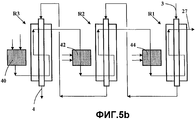
На фиг.5а и 5b изображены упрощенные схемы осуществления способа согласно изобретению в установках, содержащих несколько реакторов-теплообменников.On figa and 5b depicts simplified diagrams of the implementation of the method according to the invention in plants containing multiple reactors, heat exchangers.
Описание чертежейDescription of drawings
Фиг.1Figure 1
Загрузки F1, F2 и F3 имеют одинаковый состав и состоят из смеси по существу очищенного газа, содержащего обычно более 80 молярных % метана и от 2 до 15% этана. Поток, содержащий первую загрузку F1 с добавлением водяного пара, имеет молярное отношение Н2О/F1, составляющее обычно от 1,8 до 3,5. Этот поток входит по линии 1 в теплообменник предварительного нагрева 2а, затем проходит через реактор-теплообменник 2b, в котором проводят предварительную конверсию с водяным паром при относительно умеренной температуре выхода, обычно от 650°С до 770°С, предпочтительно от 670°С до 740°С. Реактор-теплообменник 2b является мультитрубчатым теплообменником, трубы которого содержат катализатор конверсии с водяным паром, например один из катализаторов, описанных в примерах патента US 4906603. На выходе из реактора-теплообменника 2b поток, содержащий первую загрузку F1 с добавлением водяного пара, частично превращенный в синтез-газ, подается по линии 3 в главный реактор-теплообменник R, также являющийся мультитрубчатым, в котором находится катализатор конверсии с водяным паром, обычно того же типа, что и в реакторе-теплообменнике 2b. Этот поток затем распределяется по множеству реакционных труб 38, расположенных внутри камеры 37 реактора-теплообменника R, затем после проведения конверсии с водяным паром выходит из реактора-теплообменника R по линии 4, образуя первый синтез-газ SG1, и охлаждается в теплообменнике 2а в смеси со вторым синтез-газом SG2.The feeds F1, F2 and F3 have the same composition and consist of a mixture of essentially purified gas, usually containing more than 80 molar% methane and 2 to 15% ethane. The stream containing the first charge F1 with the addition of water vapor has a molar ratio of H 2 O / F1, usually from 1.8 to 3.5. This stream enters
Загрузку F2 подают через вход для углеводородов 41а в камеру 40 частичного окисления, в которую, кроме того, подают кислород по линии 41b. В загрузку F2 и/или в подаваемый кислород обычно можно добавлять водяной пар (например, от 20 до 50 мол.% водяного пара) для снижения риска образования углерода (сажи). Температура на выходе из камеры 40 частичного окисления обычно составляет от 1100°С до 1250°С, предпочтительно от 1140°С до 1200°С. Регулировать эту температуру можно путем изменения молярного отношения О2/(углеводороды, содержащиеся в F2), часто составляющего от 0,48 до 0,85.The feed F2 is fed through a
Текучий теплоноситель HF, полученный таким образом, входит в реактор-теплообменник R, где возможно может продолжаться беспламенное горение, и передает значительную часть тепла от частичного окисления реакционным трубам 38, обеспечивая проведение конверсии с водяным паром загрузки F1. В реактор-теплообменник R вводят фракцию F3 загрузки и кислород (при помощи средств, изображенных на фиг.2) для проведения ступенчатого горения в реакторе-теплообменнике R и передачи большого количества тепла трубам для конверсии с водяным паром. Поток HF выходит из реактора-теплообменника R по линии 27 с образованием второго синтез-газа SG2. Этот синтез-газ SG2, температура которого на выходе из реактора-теплообменника R еще остается высокой, например порядка 1000°С, подают в реактор-теплообменник 2b предварительной конверсии с водяным паром загрузки F1, где его используют в качестве текучего теплоносителя, затем выходит из 2b по линии 28, смешивается с синтез-газом SG1, циркулирующим по линии 4, затем смесь SG, полученную таким образом, охлаждают в теплообменнике 2а, откуда она выходит по линии 29. Синтез-газ SG можно затем подвергнуть дополнительным видам обработки, таким как более сильное охлаждение, превращение СО при помощи пара, химическое превращение и т.д. Благодаря 2а и 2b установка на фиг.1 рекуперирует большое количество тепла, в частности, из наиболее горячего потока, выходящего из реактора-теплообменника R, т.е. SG2.The fluid coolant HF thus obtained enters the reactor-heat exchanger R, where flameless combustion may possibly continue, and transfers a significant part of the heat from partial oxidation to the
На фиг.2: реактор-теплообменник R на фиг.2 содержит 3 камеры или зоны частичного окисления, расположенные последовательно, так, что это ступенчатое частичное окисление обеспечивает более существенную передачу тепла трубам 38 для конверсии с водяным паром и/или применение максимально более низких температур HF. Эти 3 зоны: 30 (первичная зона), 32 и 34 (дополнительные зоны), находятся внутри паровой камеры 37 реактора-теплообменника R. В эти зоны 30, 32 и 34 подают углеводороды загрузки F2 (обычно с добавлением водяного пара) соответственно по линиям 31а, 33а и 35а. В них также поступает кислород соответственно по линиям 31b, 33b и 35b. Может также присутствовать водяной пар в тех же условиях, что и в установке по фиг.1.In Fig.2: the reactor-heat exchanger R in Fig.2 contains 3 chambers or partial oxidation zones arranged in series, so that this stepwise partial oxidation provides more substantial heat transfer to the
Текучий теплоноситель циркулирует внутри R в перекрестном потоке и в общем режиме противотока по линии циркуляции, изображенной на фиг.2 и обозначенной позициями 22, 23, 24, 25 и 26. Эту циркуляцию вызывает присутствие поперечин или перегородок 36 в реакторе-теплообменнике R, аналогичных поперечинам или перегородкам камеры трубчатого теплообменника и традиционной паровой камеры.The flowing fluid circulates inside R in a cross flow and in a general counterflow mode along the circulation line shown in FIG. 2 and indicated by 22, 23, 24, 25 and 26. This circulation is caused by the presence of cross members or baffles 36 in the heat exchanger reactor R, similar cross-sections or partitions of the tube heat exchanger chamber and the traditional steam chamber.
Рекуперация тепла из потоков, выходящих из реактора-теплообменника R устройства, изображенного на фиг.2, также является эффективной, но отличается от рекуперации по фиг.1: используют также два теплообменника, обозначенные 2 и 2с, но только теплообменник 2 передает тепло загрузке F1 для конверсии с водяным паром, тогда как теплообменник 2с передает тепло загрузке F2 частичного окисления с добавлением водяного пара. Таким образом происходит предварительный нагрев нескольких потоков, подаваемых в R, и в частности, загрузки для конверсии с водяным паром и загрузки F2 для частичного окисления. Можно также предварительно нагревать текучие среды, добавленные в HF в процессе ступенчатого частичного окисления, в частности углеводороды и/или водяной пар, и/или предварительно нагревать кислород.The heat recovery from the flows leaving the reactor-heat exchanger R of the device shown in FIG. 2 is also effective, but differs from the recovery in FIG. 1: two heat exchangers, designated 2 and 2c, are also used, but only
На фиг.3, которая изображает вид сверху в разрезе реактора-теплообменника R по фиг.2 над зоной 32, показан вид сверху указанных перегородок 36. Зона частичного окисления 32 содержит горелку, в которую углеводороды и кислород подают по линиям 33а и 33b, служащим для подачи по касательной в две концентрически расположенные трубы 33d и 33с с тем, чтобы осуществлять быстрое смешивание посредством вихревого контрвращения.Figure 3, which depicts a top sectional view of the reactor-heat exchanger R of Figure 2 above
Торцы реактора-теплообменника R на фиг.2 обычно имеют традиционные выпуклые днища, не изображенные на фигуре, чтобы фигура была более понятной, и R включает в себя все реакционные трубы 38.The ends of the reactor-heat exchanger R in figure 2 usually have traditional convex bottoms, not shown in the figure, so that the figure is more clear, and R includes all the
Установка на фиг.2 изображена только с одним теплообменником 2, но может также содержать реакторы-теплообменники и/или теплообменники, такие как 2а и 2b установки, изображенной на фиг.1.The plant of FIG. 2 is shown with only one
Реактор-теплообменник R на фиг.2 и 3 представляет собой только один тип реактора-теплообменника, который можно использовать для осуществления способа согласно изобретению, и другие типы реактора-теплообменника R можно использовать не выходя за рамки изобретения, включая реакторы-теплообменники со «штыковыми трубами». В этом типе реакторов-теплообменников каждая из реакционных труб 38 содержит две концентрически расположенные трубы, и загрузка для конверсии с водяным паром циркулирует последовательно в круговом пространстве, затем во внутренней центральной трубе или в противоположном направлении циркуляции, при этом входящие потоки F1 и поток SG1 соответственно входят и выходят с одного торца R.The heat exchanger reactor R in FIGS. 2 and 3 represents only one type of heat exchanger reactor that can be used to carry out the method according to the invention, and other types of heat exchanger reactor R can be used without departing from the scope of the invention, including bayonet heat exchangers pipes. " In this type of heat exchanger reactor, each of the
Установка на фиг.4 аналогична установке на фиг.2, но в ней используют внешние зоны частичного окисления, не являющиеся внутренними для R, позволяющие за счет менее компактного осуществления использовать стандартные горелки и/или зоны окисления без проблем, связанных с габаритами. В эти зоны 40, 42, 44 и 46 подают углеводороды F2 и F3 по линиям 41а, 43а, 45а и 47а соответственно. В них также подают кислород по линиям 41b, 43b, 45b и 47b соответственно. Там может также присутствовать водяной пар в тех же условиях, что и в установке по фиг.1.The installation in Fig. 4 is similar to the installation in Fig. 2, but it uses external partial oxidation zones that are not internal to R, which allow using standard burners and / or oxidation zones due to less compact implementation without problems with dimensions. Hydrocarbons F2 and F3 are supplied to these
На фиг.5а изображена установка, содержащая три реактора-теплообменника R1, R2 и R3, через которые параллельно проходят части потока, содержащего первую загрузку F1 с добавлением водяного пара, и последовательно проходит поток HF ступенчатого частичного окисления с промежуточным нагревом HF между двумя последовательными реакторами-теплообменниками. Такая установка может содержать не три, а два, четыре или в общем множество реакторов-теплообменников Ri.Fig. 5a shows a plant containing three heat exchanger reactors R1, R2, and R3 through which parts of the stream containing the first charge F1 with the addition of water vapor pass in parallel and a step-by-step partial oxidation stream HF passes through with intermediate heating HF between two successive reactors heat exchangers. Such an installation may contain not three, but two, four, or in general a plurality of reactor-heat exchangers Ri.
Установка на фиг.5b достаточно похожа на установку по фиг.5а, но в ней поток, содержащий первую загрузку F1 с добавлением водяного пара, циркулирует последовательно (ступенчатая конверсия с водяным паром) в теплообменниках R1, R2 и R3 в общем режиме противотока с потоком частичного окисления HF, также ступенчатым. Эта конфигурация обеспечивает очень высокую рекуперацию тепла и энергетическую эффективность, при этом реактор-теплообменник R1, в котором происходит предварительная конверсия с водяным паром, может работать при относительно низкой температуре. Установка на фиг.5b также может содержать не три, а два, четыре или, в общем, множество реакторов-теплообменников Ri.The installation in FIG. 5b is quite similar to the installation in FIG. 5a, but in it the stream containing the first charge F1 with the addition of water vapor is circulated sequentially (stepwise conversion with water vapor) in the heat exchangers R1, R2 and R3 in the general counterflow mode with the flow The partial oxidation of HF is also stepwise. This configuration provides a very high heat recovery and energy efficiency, while the reactor-heat exchanger R1, in which the pre-conversion with water vapor, can operate at a relatively low temperature. The installation in FIG. 5b may also comprise not three, but two, four, or, in general, a plurality of reactor heat exchangers Ri.
ПримерыExamples
Моделируют получение синтез-газа SG под давлением 2,5 МПа из природного газа в установке типа изображенной на фиг.2. Загрузки F1 и F2 имеют идентичный состав (природный газ в сочетании с метаном).Simulate the production of synthesis gas SG under a pressure of 2.5 MPa from natural gas in a plant of the type shown in figure 2. Feeds F1 and F2 have the same composition (natural gas combined with methane).
Условия ввода (линия 1) следующие: F1=природный газ с расходом (метана) 50000 нм3/час; в F1 вводят Н2О (водяной пар) в молярном отношении Н2О/F1=3 (Н2О и F1 в мол.%). Поток F1+Н2О предварительно нагревают до 600°С в теплообменнике 2, затем подают в реактор-теплообменник R под давлением 2,5 МПа, которое является давлением в установке (при моделировании потери загрузки не учитывались). После каталитической конверсии с водяным паром при температуре выхода 850°С (на линии 4) полученный первый синтез-газ SG1 смешивают со вторым синтез-газом SG2, циркулирующим на линии 27, причем смесь SG1+SG2 подают в теплообменник 2.Input conditions (line 1) are as follows: F1 = natural gas with a flow rate of (methane) 50,000 nm 3 / h; in F1, H 2 O (water vapor) is introduced in a molar ratio of H 2 O / F1 = 3 (H 2 O and F1 in mol.%). The stream F1 + H 2 O is preheated to 600 ° C in
В первую зону частичного окисления 30 по линии 31а подают 100433 нм3/час метана с добавлением насыщающего водяного пара (отношение Н2О/метан=1 мол.%), а по линии 31b 64650 нм3/час кислорода для получения путем частичного окисления первого текучего теплоносителя HF при 1150°С, который охлаждают до 1000°С в реакторе-теплообменнике R перед повторным нагреванием во второй дополнительной зоне частичного окисления 32. В эту зону 32 подают 20883 НМ3/час метана и 19776 НМ3/час кислорода с водяным паром (Н2О/метан=1 мол.%). Метан подают при 20°С, а водяной пар - в условиях насыщающего пара. Это дополнительное частичное окисление повышает температуру HF до 1150°С.HF снова передает тепло трубам 38 и его температура понижается до 845°С.100433 nm 3 / h of methane is added to the first
Затем во вторую дополнительную зону частичного окисления 34 подают метан с расходом 28285 нм3/час и кислород с расходом 12993 нм3/час с водяным паром (Н2О/метан=1 мол.%) в тех же условиях, что и в зону 32. Эта зона 34 является зоной каталитического окисления, и используется катализатор, содержащий 5 мас.% родия, такой, как описан в примере 1 патентной заявки US 2002/0004450 А1 или в примере 1 патента US 5510056. Общая смесь с HF этого дополнительного частичного каталитического окисления (эта смесь является также текучей средой HF) поднимает первоначальную температуру HF до 900°С. HF снова передает тепло трубам 38 с понижением температуры до 750°С на выходе из R с образованием второго синтез-газа SG2, который циркулирует по линии 27.Then, methane with a flow rate of 28285 nm 3 / h and oxygen with a flow rate of 12993 nm 3 / h with water vapor (H 2 O / methane = 1 mol.%) Are fed to the second additional
Второй синтез-газ SG2 смешивают с SG1 для образования общего синтез-газа SG, который охлаждают до 662°С в теплообменнике 2, затем по линии 28 вводят в теплообменник 2с, в котором его охлаждают до 546°С. Этот теплообменник 2с позволяет предварительно нагреть загрузку F2 с добавлением водяного пара до 500°С.The second synthesis gas SG2 is mixed with SG1 to form a common synthesis gas SG, which is cooled to 662 ° C in
Синтез-газы SG1, SG2 и полученный конечный синтез-газ SG (который содержит 469182 нм3 Н2+СО) имеют следующий состав в молярных % и с учетом Н2О:The synthesis gases SG1, SG2 and the resulting final synthesis gas SG (which contains 469182 nm 3 H 2 + CO) have the following composition in molar% and taking into account H 2 O:
Из предыдущего описания специалист может легко понять концепцию установки для осуществления изобретения, а также ее работу в случае, когда текучий теплоноситель HF получают в результате обычно полного горения главным образом газообразных углеводородов на воздухе, а не частичного окисления кислородом в присутствии водяного пара. В этом случае поток HF, циркулирующий по линии 28, состоит из дымовых газов под давлением и не смешивается с синтез-газом SG1, полученным после конверсии с водяным паром, циркулирующим по линии 4. Температуры, используемые для HF, в частности, на выходе из одной или нескольких дополнительных зон горения, являются одинаковыми. Этот вариант осуществления изобретения дает возможность избежать получения кислорода. Используемый воздух может быть сжат в компрессорной части газовой турбины, и текучий теплоноситель HF, полученный в результате ступенчатого горения согласно способу по изобретению, может расширяться в турбинной части газовой турбины или другой турбины после использования в качестве текучего теплоносителя для конверсии с водяным паром и предпочтительно предварительной конверсии с водяным паром. Может оказаться целесообразным проводить дополнительное горение до расширения в турбине в целях максимального использования рекуперированной механической энергии.From the previous description, one skilled in the art can easily understand the concept of the apparatus for carrying out the invention, as well as its operation in the case where the HF fluid is obtained as a result of the usually complete combustion of mainly gaseous hydrocarbons in air, and not partial oxidation by oxygen in the presence of water vapor. In this case, the HF stream circulating along
Синтез-газ SG можно затем подвергнуть конверсии СО паром для получения водорода. В этом случае часть полученного водорода после удаления СО2 (например, путем промывки аминов) можно использовать как горючее для нагревания реактора-теплообменника R, в качестве загрузки F2 и/или загрузки F3, введенной в HF в процессе ступенчатого окисления. Можно также использовать в качестве F2 и/или F3 (горючая часть HF) продувочный газ (обычно содержащий СО и остаточный метан и в частых случаях СО2), полученный после очистки выходящего потока SG путем адсорбции с балансировкой давления (адсорбция, известная также под названием PSA). Эта адсорбция обычно является конечной очисткой после конверсии с водяным паром СО, содержащегося в SG.The synthesis gas SG can then be subjected to steam conversion to produce hydrogen. In this case, a part of the hydrogen obtained after removal of CO 2 (for example, by washing the amines) can be used as fuel for heating the heat exchanger reactor R, as a charge F2 and / or a load F3 introduced into HF during the stepwise oxidation process. You can also use purge gas (usually containing CO and residual methane and, in some cases, CO 2 ) obtained as a result of purification of the SG effluent by pressure-balanced adsorption (adsorption, also known as F2 and / or F3 (combustible part HF)). PSA). This adsorption is usually the final purification after conversion with water vapor CO contained in SG.
Синтез-газ можно также использовать обычно после регулировки отношения Н2/СО (например, путем отделения избыточного водорода) для химического превращения, например, в спирты или другие кислородсодержащие соединения, или в олефины и/или в парафины.Synthesis gas can also be used usually after adjusting the H 2 / CO ratio (for example, by separating excess hydrogen) for chemical conversion, for example, to alcohols or other oxygen-containing compounds, or to olefins and / or paraffins.
Claims (12)
поток, содержащий первую загрузку F1 с добавлением водяного пара, подвергают конверсии с водяным паром для получения по меньшей мере одной фракции синтез-газа SG в по меньшей мере одном мультитрубчатом реакторе-теплообменнике R, имеющем множество реакционных труб, содержащих катализатор конверсии с водяным паром, и камеру, в которой находятся эти трубы, причем первая загрузка F1 с добавлением водяного пара циркулирует внутри множества труб в одном направлении;
указанные реакционные трубы нагревают главным образом посредством конвекции путем циркуляции в указанной камере текучего теплоносителя HF снаружи по отношению к трубам, локально в режиме перекрестного потока, но в целом в режиме противотока всей F1, в котором HF содержит по меньшей мере первый поток газа частичного или полного горения второй загрузки F2, который подвергают циркуляции в реакторе-теплообменнике R для нагревания реакционных труб, который затем смешивают в по меньшей мере одной дополнительной зоне горения внутри камеры с по меньшей мере частью третьей загрузки F3 и газом, содержащим кислород, чтобы повысить температуру указанного первого потока, затем поток полученной таким образом смеси циркулирует в реакторе-теплообменнике R для дополнительного нагревания реакционных труб до выхода из этого реактора-теплообменника;
получают синтез-газ SG из потока после конверсии с водяным паром F1 и возможно части или всего HF.1. A method of producing synthesis gas SG from a total charge F containing hydrocarbons and possibly recirculated compounds, wherein F comprises a first charge F1, a second charge F2 and a third charge F3, during which:
the stream containing the first charge F1 with the addition of water vapor is subjected to steam conversion to obtain at least one fraction of the synthesis gas SG in at least one multitubular reactor-heat exchanger R having a plurality of reaction tubes containing a steam conversion catalyst, and a chamber in which these pipes are located, the first F1 loading with the addition of water vapor circulating within the plurality of pipes in one direction;
said reaction tubes are heated mainly by convection by circulating in the said chamber a fluid coolant HF externally with respect to the tubes, locally in the cross-flow mode, but generally in the counterflow mode of the entire F1, in which the HF contains at least the first partial or full gas stream the combustion of the second charge F2, which is circulated in the reactor-heat exchanger R to heat the reaction tubes, which are then mixed in at least one additional combustion zone inside the chamber with shey least part of the third feed F3 and a gas containing oxygen to raise the temperature of said first stream, then stream the mixture thus obtained is circulated in the reactor-exchanger R for additional heating of the reaction tubes to exit the reactor-exchanger;
receive synthesis gas SG from the stream after conversion with water vapor F1 and possibly part or all of HF.
Applications Claiming Priority (2)
| Application Number | Priority Date | Filing Date | Title |
|---|---|---|---|
| FR0509668 | 2005-09-21 | ||
| FR0509668A FR2890955B1 (en) | 2005-09-21 | 2005-09-21 | PROCESS FOR PRODUCING SYNTHESIS GAS BY VAPOREFORMING IN REACTOR-EXCHANGER |
Publications (2)
| Publication Number | Publication Date |
|---|---|
| RU2006133682A RU2006133682A (en) | 2008-03-27 |
| RU2420450C2 true RU2420450C2 (en) | 2011-06-10 |
Family
ID=36178223
Family Applications (1)
| Application Number | Title | Priority Date | Filing Date |
|---|---|---|---|
| RU2006133682/05A RU2420450C2 (en) | 2005-09-21 | 2006-09-20 | Method of producing synthesis gas in heat exchanger reactor by conversion with steam |
Country Status (6)
| Country | Link |
|---|---|
| US (1) | US8025862B2 (en) |
| EP (1) | EP1767492B1 (en) |
| JP (1) | JP5124117B2 (en) |
| CA (1) | CA2559850C (en) |
| FR (1) | FR2890955B1 (en) |
| RU (1) | RU2420450C2 (en) |
Cited By (1)
| Publication number | Priority date | Publication date | Assignee | Title |
|---|---|---|---|---|
| RU2606439C2 (en) * | 2011-09-06 | 2017-01-10 | Линде Акциенгезелльшафт | Processing carbon dioxide-riched fraction from plant for producing hydrogen and carbon monoxide |
Families Citing this family (15)
| Publication number | Priority date | Publication date | Assignee | Title |
|---|---|---|---|---|
| KR101292737B1 (en) | 2007-11-02 | 2013-08-05 | 에스케이이노베이션 주식회사 | Hydrogen generating apparatus using steam reforming reaction |
| FR2932173B1 (en) * | 2008-06-05 | 2010-07-30 | Air Liquide | STEAM REFORMING PROCESS WITH ENHANCED SMOKE FLOW |
| JP5408001B2 (en) * | 2010-03-31 | 2014-02-05 | 宇部興産株式会社 | Polyimide film |
| FR2966814B1 (en) | 2010-10-28 | 2016-01-01 | IFP Energies Nouvelles | PROCESS FOR PRODUCING HYDROGEN BY VAPOREFORMING A PETROLEUM CUT WITH OPTIMIZED STEAM PRODUCTION |
| FR2967249B1 (en) * | 2010-11-09 | 2012-12-21 | Valeo Systemes Thermiques | HEAT EXCHANGER AND METHOD OF FORMING RELATED DISTURBERS |
| CA2856558C (en) | 2011-12-06 | 2019-06-11 | Hy9 Corporation | Catalyst-containing reactor system and associated methods |
| KR101422630B1 (en) * | 2011-12-30 | 2014-07-23 | 두산중공업 주식회사 | Heat exchange type prereformer |
| FR3040167B1 (en) * | 2015-08-18 | 2020-12-25 | Air Liquide | PROCESS FOR THE PRODUCTION OF SYNTHESIS GAS BY MEANS OF VAPOREFORMING REACTORS |
| ES2752674T3 (en) * | 2015-10-05 | 2020-04-06 | Air Liquide | Steam reformer for the production of synthesis gas |
| CN110121586B (en) | 2016-11-09 | 2022-01-25 | 八河流资产有限责任公司 | System and method for power production and integrated hydrogen production |
| WO2020250194A1 (en) | 2019-06-13 | 2020-12-17 | 8 Rivers Capital, Llc | Power production with cogeneration of further products |
| FR3102070B1 (en) * | 2019-10-17 | 2021-09-24 | Commissariat Energie Atomique | Shell and tube exchanger reactor allowing the staged injection of a reagent |
| EP4244182A1 (en) | 2020-11-13 | 2023-09-20 | Technip Energies France | A process for producing a hydrogen-comprising product gas from a hydrocarbon |
| US11691874B2 (en) | 2021-11-18 | 2023-07-04 | 8 Rivers Capital, Llc | Apparatuses and methods for hydrogen production |
| CN114250092B (en) * | 2022-01-12 | 2023-04-25 | 清华大学 | System and method for reducing emission of low-concentration combustible gas |
Family Cites Families (13)
| Publication number | Priority date | Publication date | Assignee | Title |
|---|---|---|---|---|
| US3839194A (en) * | 1971-11-01 | 1974-10-01 | Exxon Research Engineering Co | High severity reforming process with a platinum-iridium catalyst |
| US4337170A (en) * | 1980-01-23 | 1982-06-29 | Union Carbide Corporation | Catalytic steam reforming of hydrocarbons |
| US4650651A (en) * | 1983-06-09 | 1987-03-17 | Union Carbide Corporation | Integrated process and apparatus for the primary and secondary catalytic steam reforming of hydrocarbons |
| JPS62210047A (en) * | 1986-03-10 | 1987-09-16 | Toyo Eng Corp | Apparatus for reaction |
| US5229102A (en) * | 1989-11-13 | 1993-07-20 | Medalert, Inc. | Catalytic ceramic membrane steam-hydrocarbon reformer |
| DE4221837C1 (en) * | 1992-07-03 | 1993-08-19 | Uhde Gmbh, 4600 Dortmund, De | Shrouded catalytic reformer tube - with partially enclosed gas mixing zone, for prodn. of synthesis gas |
| US5938800A (en) * | 1997-11-13 | 1999-08-17 | Mcdermott Technology, Inc. | Compact multi-fuel steam reformer |
| EP0924162A3 (en) * | 1997-12-16 | 1999-10-20 | dbb fuel cell engines GmbH | Membrane for the separation of hydrogen, methanol reformer using this membrane and process for its operation |
| CA2413388C (en) * | 2000-06-29 | 2009-12-22 | H2Gen Innovations Inc. | Improved system for hydrogen generation through steam reforming of hydrocarbons and integrated chemical reactor for hydrogen production from hydrocarbons |
| US6497856B1 (en) * | 2000-08-21 | 2002-12-24 | H2Gen Innovations, Inc. | System for hydrogen generation through steam reforming of hydrocarbons and integrated chemical reactor for hydrogen production from hydrocarbons |
| US6394043B1 (en) * | 2000-12-19 | 2002-05-28 | Praxair Technology, Inc. | Oxygen separation and combustion apparatus and method |
| US6881394B2 (en) * | 2001-10-09 | 2005-04-19 | Conocophillips Company | Steam reformer for methane with internal hydrogen separation and combustion |
| FR2890956B1 (en) * | 2005-09-21 | 2008-04-18 | Inst Francais Du Petrole | PROCESS FOR PRODUCTION OF SYNTHESIS GAS BY VAPOREFORMING AND PARTIAL OXIDATION |
-
2005
- 2005-09-21 FR FR0509668A patent/FR2890955B1/en not_active Expired - Fee Related
-
2006
- 2006-09-14 EP EP06291447A patent/EP1767492B1/en not_active Expired - Fee Related
- 2006-09-18 CA CA2559850A patent/CA2559850C/en not_active Expired - Fee Related
- 2006-09-20 US US11/523,805 patent/US8025862B2/en not_active Expired - Fee Related
- 2006-09-20 RU RU2006133682/05A patent/RU2420450C2/en not_active IP Right Cessation
- 2006-09-21 JP JP2006255288A patent/JP5124117B2/en not_active Expired - Fee Related
Cited By (1)
| Publication number | Priority date | Publication date | Assignee | Title |
|---|---|---|---|---|
| RU2606439C2 (en) * | 2011-09-06 | 2017-01-10 | Линде Акциенгезелльшафт | Processing carbon dioxide-riched fraction from plant for producing hydrogen and carbon monoxide |
Also Published As
| Publication number | Publication date |
|---|---|
| EP1767492A3 (en) | 2007-04-04 |
| EP1767492A2 (en) | 2007-03-28 |
| US20070092436A1 (en) | 2007-04-26 |
| JP5124117B2 (en) | 2013-01-23 |
| FR2890955B1 (en) | 2008-02-01 |
| EP1767492B1 (en) | 2011-08-24 |
| FR2890955A1 (en) | 2007-03-23 |
| CA2559850C (en) | 2013-12-03 |
| US8025862B2 (en) | 2011-09-27 |
| JP2007084429A (en) | 2007-04-05 |
| CA2559850A1 (en) | 2007-03-21 |
| RU2006133682A (en) | 2008-03-27 |
Similar Documents
| Publication | Publication Date | Title |
|---|---|---|
| RU2420450C2 (en) | Method of producing synthesis gas in heat exchanger reactor by conversion with steam | |
| RU2418739C2 (en) | Method of producing synthetic gas through conversion with water vapour in heat exchange reactor | |
| KR960014902B1 (en) | Reformation in a plate-fin exchanger | |
| US6981994B2 (en) | Production enhancement for a reactor | |
| US7504048B2 (en) | Axial convective reformer | |
| JPS6158801A (en) | Method of improving hydrocarbon and reactor | |
| CN100548881C (en) | Pseudo-isothermal synthetic ammonia method and apparatus | |
| JP2003525115A (en) | Endothermic reaction process and device | |
| JPS62163268A (en) | Method of creating electricity by fuel cell | |
| CN1318798C (en) | Burning method of fuel reforming appts. | |
| WO1998014536A1 (en) | Method for hydrocarbon steam reforming | |
| US6793700B2 (en) | Apparatus and method for production of synthesis gas using radiant and convective reforming | |
| JP5963848B2 (en) | Non-catalytic recuperation reformer | |
| US9803153B2 (en) | Radiant non-catalytic recuperative reformer | |
| EP4105170A1 (en) | Process and plant for flexible production of syngas from hydrocarbons | |
| KR20240017375A (en) | Heat exchange reactor with reduced metal dusting | |
| KR20010049386A (en) | Reactor for carrying out a non-adiabatic process | |
| KR20240017021A (en) | Heat exchange reactor for CO2 shift | |
| CN117414767A (en) | Combined reformer |
Legal Events
| Date | Code | Title | Description |
|---|---|---|---|
| MM4A | The patent is invalid due to non-payment of fees |
Effective date: 20200921 |