EP1767492B1 - Process for the production of synthesis gas by steam reforming in an exchanger-reactor - Google Patents
Process for the production of synthesis gas by steam reforming in an exchanger-reactor Download PDFInfo
- Publication number
- EP1767492B1 EP1767492B1 EP06291447A EP06291447A EP1767492B1 EP 1767492 B1 EP1767492 B1 EP 1767492B1 EP 06291447 A EP06291447 A EP 06291447A EP 06291447 A EP06291447 A EP 06291447A EP 1767492 B1 EP1767492 B1 EP 1767492B1
- Authority
- EP
- European Patent Office
- Prior art keywords
- exchanger
- reactor
- stream
- steam
- feed
- Prior art date
- Legal status (The legal status is an assumption and is not a legal conclusion. Google has not performed a legal analysis and makes no representation as to the accuracy of the status listed.)
- Expired - Fee Related
Links
Images

Classifications
-
- C—CHEMISTRY; METALLURGY
- C01—INORGANIC CHEMISTRY
- C01B—NON-METALLIC ELEMENTS; COMPOUNDS THEREOF; METALLOIDS OR COMPOUNDS THEREOF NOT COVERED BY SUBCLASS C01C
- C01B3/00—Hydrogen; Gaseous mixtures containing hydrogen; Separation of hydrogen from mixtures containing it; Purification of hydrogen
- C01B3/02—Production of hydrogen or of gaseous mixtures containing a substantial proportion of hydrogen
- C01B3/32—Production of hydrogen or of gaseous mixtures containing a substantial proportion of hydrogen by reaction of gaseous or liquid organic compounds with gasifying agents, e.g. water, carbon dioxide, air
- C01B3/34—Production of hydrogen or of gaseous mixtures containing a substantial proportion of hydrogen by reaction of gaseous or liquid organic compounds with gasifying agents, e.g. water, carbon dioxide, air by reaction of hydrocarbons with gasifying agents
- C01B3/38—Production of hydrogen or of gaseous mixtures containing a substantial proportion of hydrogen by reaction of gaseous or liquid organic compounds with gasifying agents, e.g. water, carbon dioxide, air by reaction of hydrocarbons with gasifying agents using catalysts
- C01B3/384—Production of hydrogen or of gaseous mixtures containing a substantial proportion of hydrogen by reaction of gaseous or liquid organic compounds with gasifying agents, e.g. water, carbon dioxide, air by reaction of hydrocarbons with gasifying agents using catalysts the catalyst being continuously externally heated
-
- B—PERFORMING OPERATIONS; TRANSPORTING
- B01—PHYSICAL OR CHEMICAL PROCESSES OR APPARATUS IN GENERAL
- B01J—CHEMICAL OR PHYSICAL PROCESSES, e.g. CATALYSIS OR COLLOID CHEMISTRY; THEIR RELEVANT APPARATUS
- B01J8/00—Chemical or physical processes in general, conducted in the presence of fluids and solid particles; Apparatus for such processes
- B01J8/02—Chemical or physical processes in general, conducted in the presence of fluids and solid particles; Apparatus for such processes with stationary particles, e.g. in fixed beds
- B01J8/06—Chemical or physical processes in general, conducted in the presence of fluids and solid particles; Apparatus for such processes with stationary particles, e.g. in fixed beds in tube reactors; the solid particles being arranged in tubes
- B01J8/067—Heating or cooling the reactor
-
- C—CHEMISTRY; METALLURGY
- C01—INORGANIC CHEMISTRY
- C01B—NON-METALLIC ELEMENTS; COMPOUNDS THEREOF; METALLOIDS OR COMPOUNDS THEREOF NOT COVERED BY SUBCLASS C01C
- C01B3/00—Hydrogen; Gaseous mixtures containing hydrogen; Separation of hydrogen from mixtures containing it; Purification of hydrogen
- C01B3/02—Production of hydrogen or of gaseous mixtures containing a substantial proportion of hydrogen
- C01B3/32—Production of hydrogen or of gaseous mixtures containing a substantial proportion of hydrogen by reaction of gaseous or liquid organic compounds with gasifying agents, e.g. water, carbon dioxide, air
- C01B3/34—Production of hydrogen or of gaseous mixtures containing a substantial proportion of hydrogen by reaction of gaseous or liquid organic compounds with gasifying agents, e.g. water, carbon dioxide, air by reaction of hydrocarbons with gasifying agents
- C01B3/38—Production of hydrogen or of gaseous mixtures containing a substantial proportion of hydrogen by reaction of gaseous or liquid organic compounds with gasifying agents, e.g. water, carbon dioxide, air by reaction of hydrocarbons with gasifying agents using catalysts
- C01B3/382—Multi-step processes
-
- C—CHEMISTRY; METALLURGY
- C01—INORGANIC CHEMISTRY
- C01B—NON-METALLIC ELEMENTS; COMPOUNDS THEREOF; METALLOIDS OR COMPOUNDS THEREOF NOT COVERED BY SUBCLASS C01C
- C01B3/00—Hydrogen; Gaseous mixtures containing hydrogen; Separation of hydrogen from mixtures containing it; Purification of hydrogen
- C01B3/02—Production of hydrogen or of gaseous mixtures containing a substantial proportion of hydrogen
- C01B3/32—Production of hydrogen or of gaseous mixtures containing a substantial proportion of hydrogen by reaction of gaseous or liquid organic compounds with gasifying agents, e.g. water, carbon dioxide, air
- C01B3/34—Production of hydrogen or of gaseous mixtures containing a substantial proportion of hydrogen by reaction of gaseous or liquid organic compounds with gasifying agents, e.g. water, carbon dioxide, air by reaction of hydrocarbons with gasifying agents
- C01B3/38—Production of hydrogen or of gaseous mixtures containing a substantial proportion of hydrogen by reaction of gaseous or liquid organic compounds with gasifying agents, e.g. water, carbon dioxide, air by reaction of hydrocarbons with gasifying agents using catalysts
- C01B3/386—Catalytic partial combustion
-
- B—PERFORMING OPERATIONS; TRANSPORTING
- B01—PHYSICAL OR CHEMICAL PROCESSES OR APPARATUS IN GENERAL
- B01J—CHEMICAL OR PHYSICAL PROCESSES, e.g. CATALYSIS OR COLLOID CHEMISTRY; THEIR RELEVANT APPARATUS
- B01J2208/00—Processes carried out in the presence of solid particles; Reactors therefor
- B01J2208/00008—Controlling the process
- B01J2208/00017—Controlling the temperature
- B01J2208/00106—Controlling the temperature by indirect heat exchange
- B01J2208/00168—Controlling the temperature by indirect heat exchange with heat exchange elements outside the bed of solid particles
- B01J2208/00212—Plates; Jackets; Cylinders
- B01J2208/00221—Plates; Jackets; Cylinders comprising baffles for guiding the flow of the heat exchange medium
-
- C—CHEMISTRY; METALLURGY
- C01—INORGANIC CHEMISTRY
- C01B—NON-METALLIC ELEMENTS; COMPOUNDS THEREOF; METALLOIDS OR COMPOUNDS THEREOF NOT COVERED BY SUBCLASS C01C
- C01B2203/00—Integrated processes for the production of hydrogen or synthesis gas
- C01B2203/02—Processes for making hydrogen or synthesis gas
- C01B2203/0205—Processes for making hydrogen or synthesis gas containing a reforming step
- C01B2203/0227—Processes for making hydrogen or synthesis gas containing a reforming step containing a catalytic reforming step
- C01B2203/0233—Processes for making hydrogen or synthesis gas containing a reforming step containing a catalytic reforming step the reforming step being a steam reforming step
-
- C—CHEMISTRY; METALLURGY
- C01—INORGANIC CHEMISTRY
- C01B—NON-METALLIC ELEMENTS; COMPOUNDS THEREOF; METALLOIDS OR COMPOUNDS THEREOF NOT COVERED BY SUBCLASS C01C
- C01B2203/00—Integrated processes for the production of hydrogen or synthesis gas
- C01B2203/02—Processes for making hydrogen or synthesis gas
- C01B2203/025—Processes for making hydrogen or synthesis gas containing a partial oxidation step
- C01B2203/0255—Processes for making hydrogen or synthesis gas containing a partial oxidation step containing a non-catalytic partial oxidation step
-
- C—CHEMISTRY; METALLURGY
- C01—INORGANIC CHEMISTRY
- C01B—NON-METALLIC ELEMENTS; COMPOUNDS THEREOF; METALLOIDS OR COMPOUNDS THEREOF NOT COVERED BY SUBCLASS C01C
- C01B2203/00—Integrated processes for the production of hydrogen or synthesis gas
- C01B2203/02—Processes for making hydrogen or synthesis gas
- C01B2203/025—Processes for making hydrogen or synthesis gas containing a partial oxidation step
- C01B2203/0261—Processes for making hydrogen or synthesis gas containing a partial oxidation step containing a catalytic partial oxidation step [CPO]
-
- C—CHEMISTRY; METALLURGY
- C01—INORGANIC CHEMISTRY
- C01B—NON-METALLIC ELEMENTS; COMPOUNDS THEREOF; METALLOIDS OR COMPOUNDS THEREOF NOT COVERED BY SUBCLASS C01C
- C01B2203/00—Integrated processes for the production of hydrogen or synthesis gas
- C01B2203/02—Processes for making hydrogen or synthesis gas
- C01B2203/0283—Processes for making hydrogen or synthesis gas containing a CO-shift step, i.e. a water gas shift step
-
- C—CHEMISTRY; METALLURGY
- C01—INORGANIC CHEMISTRY
- C01B—NON-METALLIC ELEMENTS; COMPOUNDS THEREOF; METALLOIDS OR COMPOUNDS THEREOF NOT COVERED BY SUBCLASS C01C
- C01B2203/00—Integrated processes for the production of hydrogen or synthesis gas
- C01B2203/04—Integrated processes for the production of hydrogen or synthesis gas containing a purification step for the hydrogen or the synthesis gas
- C01B2203/0415—Purification by absorption in liquids
-
- C—CHEMISTRY; METALLURGY
- C01—INORGANIC CHEMISTRY
- C01B—NON-METALLIC ELEMENTS; COMPOUNDS THEREOF; METALLOIDS OR COMPOUNDS THEREOF NOT COVERED BY SUBCLASS C01C
- C01B2203/00—Integrated processes for the production of hydrogen or synthesis gas
- C01B2203/04—Integrated processes for the production of hydrogen or synthesis gas containing a purification step for the hydrogen or the synthesis gas
- C01B2203/042—Purification by adsorption on solids
- C01B2203/043—Regenerative adsorption process in two or more beds, one for adsorption, the other for regeneration
-
- C—CHEMISTRY; METALLURGY
- C01—INORGANIC CHEMISTRY
- C01B—NON-METALLIC ELEMENTS; COMPOUNDS THEREOF; METALLOIDS OR COMPOUNDS THEREOF NOT COVERED BY SUBCLASS C01C
- C01B2203/00—Integrated processes for the production of hydrogen or synthesis gas
- C01B2203/08—Methods of heating or cooling
- C01B2203/0805—Methods of heating the process for making hydrogen or synthesis gas
- C01B2203/0811—Methods of heating the process for making hydrogen or synthesis gas by combustion of fuel
- C01B2203/0822—Methods of heating the process for making hydrogen or synthesis gas by combustion of fuel the fuel containing hydrogen
-
- C—CHEMISTRY; METALLURGY
- C01—INORGANIC CHEMISTRY
- C01B—NON-METALLIC ELEMENTS; COMPOUNDS THEREOF; METALLOIDS OR COMPOUNDS THEREOF NOT COVERED BY SUBCLASS C01C
- C01B2203/00—Integrated processes for the production of hydrogen or synthesis gas
- C01B2203/08—Methods of heating or cooling
- C01B2203/0805—Methods of heating the process for making hydrogen or synthesis gas
- C01B2203/0838—Methods of heating the process for making hydrogen or synthesis gas by heat exchange with exothermic reactions, other than by combustion of fuel
- C01B2203/0844—Methods of heating the process for making hydrogen or synthesis gas by heat exchange with exothermic reactions, other than by combustion of fuel the non-combustive exothermic reaction being another reforming reaction as defined in groups C01B2203/02 - C01B2203/0294
-
- C—CHEMISTRY; METALLURGY
- C01—INORGANIC CHEMISTRY
- C01B—NON-METALLIC ELEMENTS; COMPOUNDS THEREOF; METALLOIDS OR COMPOUNDS THEREOF NOT COVERED BY SUBCLASS C01C
- C01B2203/00—Integrated processes for the production of hydrogen or synthesis gas
- C01B2203/12—Feeding the process for making hydrogen or synthesis gas
- C01B2203/1205—Composition of the feed
- C01B2203/1211—Organic compounds or organic mixtures used in the process for making hydrogen or synthesis gas
- C01B2203/1235—Hydrocarbons
- C01B2203/1241—Natural gas or methane
-
- C—CHEMISTRY; METALLURGY
- C01—INORGANIC CHEMISTRY
- C01B—NON-METALLIC ELEMENTS; COMPOUNDS THEREOF; METALLOIDS OR COMPOUNDS THEREOF NOT COVERED BY SUBCLASS C01C
- C01B2203/00—Integrated processes for the production of hydrogen or synthesis gas
- C01B2203/12—Feeding the process for making hydrogen or synthesis gas
- C01B2203/1288—Evaporation of one or more of the different feed components
- C01B2203/1294—Evaporation by heat exchange with hot process stream
-
- C—CHEMISTRY; METALLURGY
- C01—INORGANIC CHEMISTRY
- C01B—NON-METALLIC ELEMENTS; COMPOUNDS THEREOF; METALLOIDS OR COMPOUNDS THEREOF NOT COVERED BY SUBCLASS C01C
- C01B2203/00—Integrated processes for the production of hydrogen or synthesis gas
- C01B2203/14—Details of the flowsheet
- C01B2203/141—At least two reforming, decomposition or partial oxidation steps in parallel
-
- C—CHEMISTRY; METALLURGY
- C01—INORGANIC CHEMISTRY
- C01B—NON-METALLIC ELEMENTS; COMPOUNDS THEREOF; METALLOIDS OR COMPOUNDS THEREOF NOT COVERED BY SUBCLASS C01C
- C01B2203/00—Integrated processes for the production of hydrogen or synthesis gas
- C01B2203/14—Details of the flowsheet
- C01B2203/142—At least two reforming, decomposition or partial oxidation steps in series
- C01B2203/143—Three or more reforming, decomposition or partial oxidation steps in series
-
- Y—GENERAL TAGGING OF NEW TECHNOLOGICAL DEVELOPMENTS; GENERAL TAGGING OF CROSS-SECTIONAL TECHNOLOGIES SPANNING OVER SEVERAL SECTIONS OF THE IPC; TECHNICAL SUBJECTS COVERED BY FORMER USPC CROSS-REFERENCE ART COLLECTIONS [XRACs] AND DIGESTS
- Y02—TECHNOLOGIES OR APPLICATIONS FOR MITIGATION OR ADAPTATION AGAINST CLIMATE CHANGE
- Y02E—REDUCTION OF GREENHOUSE GAS [GHG] EMISSIONS, RELATED TO ENERGY GENERATION, TRANSMISSION OR DISTRIBUTION
- Y02E60/00—Enabling technologies; Technologies with a potential or indirect contribution to GHG emissions mitigation
- Y02E60/30—Hydrogen technology
- Y02E60/32—Hydrogen storage
-
- Y—GENERAL TAGGING OF NEW TECHNOLOGICAL DEVELOPMENTS; GENERAL TAGGING OF CROSS-SECTIONAL TECHNOLOGIES SPANNING OVER SEVERAL SECTIONS OF THE IPC; TECHNICAL SUBJECTS COVERED BY FORMER USPC CROSS-REFERENCE ART COLLECTIONS [XRACs] AND DIGESTS
- Y02—TECHNOLOGIES OR APPLICATIONS FOR MITIGATION OR ADAPTATION AGAINST CLIMATE CHANGE
- Y02P—CLIMATE CHANGE MITIGATION TECHNOLOGIES IN THE PRODUCTION OR PROCESSING OF GOODS
- Y02P20/00—Technologies relating to chemical industry
- Y02P20/10—Process efficiency
Definitions
- the object of the invention relates to the production of synthesis gas from natural gas or light hydrocarbons: methane, ethane, propane, butane, or even hydrocarbons having less than 10 carbon atoms, and mixtures thereof.
- Synthesis gas is a mixture composed mainly of (after removal of water) hydrogen, carbon monoxide and carbon dioxide. It often contains small amounts of residual hydrocarbons, typically methane.
- the synthesis gas can be used to produce hydrogen. It can also be used to produce liquid compounds by chemical conversion, for example oxygen compounds (methanol, dimethyl ether, etc.), or hydrocarbons, especially olefinic or paraffinic hydrocarbons.
- steam reforming (the most used process), partial oxidation and the autothermal process.
- SMR steam methane reforming
- synthesis gas mainly contains (off steam) a mixture of carbon monoxide and hydrogen. This operation is endothermic.
- catalyst filled tubes generally a nickel catalyst, for example comprising from 6 to 25% by weight of nickel deposited on a support mainly comprising alumina, or a mixture of alumina and one or more other refractory compounds.
- the tubes are typically heated by radiation in tubular furnaces. The hottest points of the flame must be kept sufficiently distant from the tubes so that there is no excessive overheating and because of this, the furnaces used are bulky and expensive.
- the partial oxidation (known under the acronym POX which comes from the English “partial oxidation” which means partial oxidation), consists of forming under combustion under substoichiometric conditions a mixture at high temperature - generally between 1000 ° C and 1600 ° C - hydrocarbons and air or oxygen, to oxidize the hydrocarbons and obtain a synthesis gas. This process uses large amounts of oxygen when air can not be used (when a synthesis gas without nitrogen is required).
- the autothermal process achieves a partial oxidation immediately followed by a catalytic steam reforming at high temperature adiabatic, for example in the range of outlet temperatures: 900 ° C -1000 ° C.
- This process achieves a series combination of the two previous reaction modes. It consumes less oxygen than the POX process, but requires a catalytic bed.
- An object of the process according to the invention is to produce synthesis gas from light hydrocarbons in a much more compact installation than a conventional (oven) steam reforming plant, typically requiring less oxygen than the POX processes and autothermal, or no oxygen at all, and limiting the combustion means implemented.
- the method according to the invention is therefore very efficient from the energy point of view and this with a small footprint and a limited investment cost.
- the invention also makes it possible to reduce the highest temperatures used while maintaining energy efficiency at a high level. This increases the reliability and the lifetime of the installation.
- the process according to the invention uses, in particular, an HF heating fluid for carrying out the thermal transfers necessary for endothermic steam reforming reactions.
- One of the most important aspects of this process is the use, in a reactor-exchanger R performing a steam reforming, of an HF heating fluid obtained according to a staged combustion, making it possible to transfer heat several times to the reaction medium.
- steam reforming with one or more intermediate combustion (s) to raise the temperature level of this HF heating fluid.
- s intermediate combustion
- a smaller volume of gas is used to transfer a given amount of heat. This results in an energetic gain.
- the compactness of the installation is significantly greater than that of a conventional steam-reforming installation in an oven.
- the multiple heating (combustion) of HF also makes it possible to limit the maximum temperatures used, and thus to increase the lifetime of the installation.
- the fillers F1, F2, and F3 can be various, gaseous and / or liquid. They may be of the same composition or of different compositions. Most often, however, the feeds F1, F2, and F3 are essentially gaseous hydrocarbons at a pressure of 2 MPa and at a temperature of 20 ° C. Typically, F1, F2, and F3 are of identical composition and come from a natural gas, or purified, or from a gaseous mixture composed mainly, in mol%, of hydrocarbons having less than 5 carbon atoms.
- the term "charge" designates both a hydrocarbon feedstock and a recycling stream derived from the hydrocarbon feedstock.
- F 2 and / or F 3 can also comprise or be constituted by a recycle stream, in particular a stream comprising a fraction separated downstream such that a fraction of SG separated by adsorption and desorption with a pressure swing for the hydrogen production (typically an adsorption purge gas called PSA).
- PSA a pressure swing for the hydrogen production
- F2 and / or F3 a purge gas containing CO and residual methane, and often CO2.
- substantially pure hydrogen especially a fraction of the hydrogen produced, can be used for F 2 and / or F 3 when SG is used for the production of hydrogen.
- staged combustion makes it possible to transfer a large amount of heat, supplied in increments of temperature, with intermediate cooling (heat transfer for steam reforming), without reaching the particularly high temperatures that would be obtained by carrying out all the combustion in one step.
- staged combustion with intermediate heat transfer (s) can transfer a significantly greater amount of heat for a given volume of combustion gas, or a quantity of heat. identical heat for a smaller flue gas volume.
- the initial combustion zone may be internal or external to the shell of reactor-exchanger R.
- the combustion may be partial or total, and use oxygen or air, or oxygen enriched air as the oxidizer.
- a partial oxidation stream of hydrocarbons with oxygen typically at a pressure of between 0.5 and 12 MPa, substantially free of nitrogen and preferably comprising water.
- Such a HF fluid at high pressure and comprising hydrogen has very good thermal fluid properties (high heat exchange coefficient).
- a total hydrocarbon combustion gas is also used in air, typically at a pressure of between 0.4 and 4 MPa.
- the zone (s) complementary (s) combustion (s) is (are) disposed (s) inside the shell of the reactor-exchanger R.
- the initial combustion zone can also be a zone internal to the reactor-exchanger.
- the complementary combustion zone is a zone free of reaction tubes and substantially contiguous to the inner wall of the shell of the reactor-exchanger R.
- this first characteristic variant of the invention avoids the formation of flames in contact with the reaction tubes.
- This can be done, according to a first embodiment of the combustion, by limiting the presence of flames to one or more combustion zone (s) free (s) of reaction tubes, in particular contiguous (s) to the inner wall of the Reactor-reactor heat exchanger R.
- One can use in particular a burner (s) flat or short flame of known type, and / or multiple small burners thus giving smaller flames.
- at least one part of F3 and an oxygen-containing gas (for example air or O2) are injected at a point inside the shell of the reactor-exchanger.
- the homogeneous combustion is indeed favored by a very turbulent mixture of reagents and by their recirculation.
- the combustion is carried out in homogeneous mode in the immediate vicinity of the steam reforming tubes and heat transfer is carried out. immediate heat of combustion to the tubes.
- the combustion in homogeneous regime can then continue at the steam reforming tubes because it does not generate hot spots that can damage them. It then becomes possible to make the temperatures in the reactor-exchanger more homogeneous, which makes it possible to optimize the heat transfers, to reduce the number of complementary zones of combustion and / or to limit the maximum effective local temperature of the HF fluid. which is favorable from the point of view of the life of the equipment.
- At least one part of F3 and an oxygen-containing gas upstream of a catalytic combustion zone are injected at a point inside the shell of the reactor-exchanger, under conditions where the temperature of the mixture obtained is lower than the temperature or the combustion occurs with a flame.
- Catalytic combustion is a well known technique in the field of combustion, and can use various catalysts. For example, one can refer to patents or patent applications US20050081443 ; US 5,980,843 ; US 5,405,260 ; EP 0 689 870 B1 ; EP 0 712 661 B1 .
- the initial and final temperature zones for performing catalytic combustion under the best conditions can be determined by tests for a given catalyst.
- Preferred initial mixing temperatures are below 900 ° C, and often between 800 ° C and 880 ° C.
- Preferred end temperatures are below 1000 ° C, and often between 800 ° C and 980 ° C.
- the catalytic combustion can advantageously be limited to the least hot part of the reactor-exchanger R.
- the combustion zone catalytic is typically located in the first half of the reactor-exchanger relative to this end.
- the combustion zone initial can be disposed outside the shell (37) of the reactor-exchanger R. This option leads to a less compact embodiment, but allows standard sizing for the burners and the combustion zone.
- the circulation of the HF heating fluid can be carried out in different ways.
- the stream comprising the first charge F1 added with water vapor circulates in the reactor-exchanger essentially in one direction, and the heating fluid HF circulates at least globally counter-current relative to F1 (this is that is to say either in pure counter-current, HF circulating parallel to the tubes, or locally cross-flow, but overall against the overall current).
- a cocurrent circulation is however possible.
- the HF heating fluid circulates at least generally cocurrently with respect to F1 (co-current pure or whole).
- the stream comprising the first charge F1 supplemented with water vapor is typically preheated between 500 ° C. and 740 ° C. (and preferably between 580 and 700 ° C.) before it enters the reactor-exchanger R.
- the temperature of the steam reforming effluent SG1 at the outlet of reactor-exchanger R is typically between 800 ° C. and 950 ° C. (and preferably between 820 and 900 ° C.), and the temperature of HF at the outlet of reactor-exchanger R is typically between 850 ° C and 1150 ° C and preferably between 900 ° C and 1050 ° C.
- the invention also relates to a process for producing hydrogen from a synthesis gas comprising the synthesis gas SG from the process described above, according to any one of its variants.
- the fuel portion of the HF (or F2 and / or F3) heating fluid may consist essentially of a fraction of substantially pure hydrogen produced from SG.
- F2 and / or F3 may also comprise a purge gas resulting from a PSA (pressure swing) adsorption purification step carried out on a stream derived from SG. This makes it possible to advantageously use this purge gas.
- PSA pressure swing
- the fillers F1, F2, and F3 are of identical composition, and consist of a mixture of a generally purified gas, typically comprising more than 80 mol% of methane and 2 to 15% of ethane.
- the stream comprising the first charge F1 added with water vapor has a molar ratio H2O / F1 typically between 1.8 and 3.5.
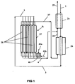
- This stream enters via the line 1 in the preheating exchanger 2a, then passes through the reactor-exchanger 2b in which a pre-evaporation is performed with a relatively moderate outlet temperature, typically between 650 ° C. and 770 ° C., preferably between 670 ° C. and 670 ° C. ° C and 740 ° C.
- the reactor-exchanger 2b is a multi-tubular tube exchanger containing a steam reforming catalyst, for example one of the catalysts described in the examples of the patent. US 4,906,603 .
- the stream comprising the first charge F1 supplemented with steam, partially converted into synthesis gas feeds via line 3 the reactor-main heat exchanger R, also multi-tubular tube containing a steam reforming catalyst, typically of the same type as that of the reactor -Exchanger 2b.
- This current is then distributed in a plurality of reaction tubes 38 arranged inside the calender 37 of the reactor-exchanger R, then, after steam reforming, leaves the reactor-exchanger R via line 4, forming a first synthesis gas SG1 and is cooled in the exchanger 2a in admixture with the second syngas SG2.
- the feed F2 feeds via a hydrocarbon inlet 41a a partial oxidation chamber 40, further supplied with oxygen by the line 41b.
- the feed F 2 and / or the supply of oxygen can typically be supplemented with steam (for example 20% to 50% molar water vapor) to limit the risk of carbon formation (soot).
- the exit temperatures of the partial oxidation chamber 40 are typically between 1100 ° C and 1250 ° C, preferably between 1140 ° C and 1200 ° C.
- the control of this temperature can be achieved by modulation of the molar ratio O2 / (F2 hydrocarbons), often between 0.48 and 0.85.
- the heating fluid HF thus formed enters the reactor-exchanger R, where a flame-free combustion can possibly continue, and transfers a substantial part of the partial oxidation heat to the reaction tubes 38, thus allowing the steam reforming of F1.
- Inside reactor-exchanger R there is added a fraction F3 of the feed, and oxygen (by means which are represented in FIG.
- the HF stream exits the reactor-exchanger R via the line 27 to form a second synthesis gas SG2.
- This synthesis gas SG2 the temperature at the outlet of the reactor-exchanger R is still high, for example of the order of 1000 ° C, feeds the reactor-exchanger 2b pre-steam reforming F1 load, or it is used as a heating fluid, then leaves 2b via the line 28, is mixed with the synthesis gas SG1 flowing in the line 4, then the SG mixture thus formed is cooled in the exchanger 2a, which it leaves via the line 29.
- SG synthesis gas can then undergo additional treatments such as further cooling, conversion of CO to steam, chemical conversion etc ... Thanks to 2a and 2b, the installation of the figure 1 performs a good thermal recovery, in particular on the hottest effluent of reactor-exchanger R, that is to say SG2.
- the reactor-exchanger R of the figure 2 comprises 3 chambers, or partial oxidation zones in series, so that this staged partial oxidation allows greater heat transfer to the steam reforming tubes 38 and / or the use of lower maximum temperatures for HF.
- These 3 zones: 30 (initial zone), 32 and 34 (complementary zones) are internal to the calandria 37 of R.
- These zones 30, 32, and 34 are supplied with hydrocarbons from the charge F2 for the initial zone and the charge.
- F3 for the complementary zones (typically added with water vapor) via lines 31a, 33a, and 35a, respectively. They are also supplied with oxygen via lines 31b, 33b and 35b, respectively.
- the heating fluid circulates inside R with cross flow and global countercurrent by following the circulation line on the figure 2 and indicated by the references 22, 23, 24, 25, and 26.
- This circulation is imposed by the presence of spacers or baffles 36 in the reactor-exchanger R, similar to the spacers or baffles of the shell of a heat exchanger heat pipe and conventional calender.
- the heat recovery on the effluents of the reactor-exchanger R from the device of the figure 2 performs well, but differs from that of figure 1
- Two exchangers are also used, which are referenced 2 and 2c, but only the exchanger 2 transmits heat to the steam reforming charge F1 while the exchanger 2c transmits heat to the partial oxidation charge F2, added with water vapour. Preheating of several currents supplying R, and in particular of the steam reforming charge and the partial oxidation charge F 2, is thus obtained. It is also possible to preheat the added fluids with HF during the staged partial oxidation, in particular the hydrocarbons and / or the steam, and / or to preheat the oxygen.
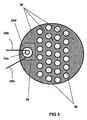
- the figure 3 which represents a view from above of a section of the reactor-exchanger R of the figure 2 above the zone 32 shows in plan view these spacers 36.
- the partial oxidation zone 32 comprises a burner with introduction of hydrocarbons and oxygen via the lines 33a and 33b which feed tangentially two concentric tubes 33d and 33c for create a rapid mixture by contrarotating vortices.
- the ends of the reactor-exchanger R of the figure 2 typically comprise conventional curved bottoms, not shown for the sake of clarity of the figure, and R encompasses all of the reaction tubes 38.
- the installation of the figure 2 represents only a heat exchanger 2, but could also include reactor-exchangers and / or heat exchangers such as 2a and 2b of the installation of the figure 1 .
- the reactor-exchanger R figures 2 and 3 represents only one type of reactor-exchanger used for carrying out the process according to the invention and other types of reactor-exchanger R can be used without departing from the scope of the invention.
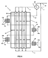
- the installation of the figure 4 which is not according to the invention, is quite close to that of the figure 2 , but uses external partial oxidation zones and not internal to R, allowing, at the cost of a less compact embodiment, to use burners and / or standard oxidation zones without problems of space.
- These zones 40, 42 and 44 are fed with hydrocarbons F2 and F3 via lines 41a, 43a and 45a, respectively. They are also supplied with oxygen via lines 41b, 43b and 45b, respectively. There may also be presence of water vapor under the same conditions as for the installation of the figure 1 .
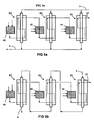
- the figure 5a represents an installation comprising three reactor-exchangers R1, R2 and R3, traversed in parallel by portions of the stream comprising the first F1 charge added with water vapor, and crossed in series by a staged partial oxidation HF stream, with intermediate heating of HF between two successive reactor-exchangers.
- Such an installation could comprise not three, but two, four, or generally several Ri-exchange reactors.
- the installation of the figure 5b is pretty close to that of the figure 5a , but uses for the stream comprising the first charge F1 supplemented with water vapor a series circulation (step steam reforming) in the exchangers R1, R2, R3, in countercurrent with the total flow of partial oxidation HF, also storied.
- the reactor-exchanger R1 which performs a pre-reforming process that can be operated at a relatively low temperature.
- the installation of the figure 5b could include not three, but two, four, or generally more Ri-Reactors-interchangers.
- F1 and F2 fillers are identical in composition (natural gas assimilated to methane).
- the stream F1 + H2O is preheated to 600 ° C in the exchanger 2, then feeds the reactor-exchanger R under a pressure of 2.5 MPa which is the pressure of the installation (for the simulation, we do not have taken into account the losses of charges).
- the first synthesis gas SG1 obtained is mixed with the second synthesis gas SG2 circulating in line 27, the mixture SG1 + SG2 feeding the heat exchanger 2.
- a first HF heating fluid at 1150 ° C, which is cooled to 1000 ° C in the reactor-exchanger R before being reheated in the second partial partial oxidation zone 32.
- the methane is fed at 20 ° C, and the steam under saturated steam conditions.
- This additional partial oxidation raises the temperature of HF to 1150 ° C.
- HF again transmits heat to the tubes 38, and its temperature drops to 845 ° C.
- This zone 34 is a catalytic oxidation zone, and uses a catalyst comprising 5% by weight of rhodium such as that described in Example 1 of the patent application. US 2002/0004450 A1 , or that of example 1 of the patent US5,510,056 .
- the global mixture with HF of this complementary catalytic partial oxidation raises the initial temperature of HF to 900 ° C.
- HF again transmits heat to the tubes 38, and its temperature drops to 750 ° C. at its outlet from R, forming a second synthesis gas SG2 which circulates in the line 27.
- This second synthesis gas SG2 is mixed with SG1 to form the overall synthesis gas SG, which is cooled to 662 ° C in the heat exchanger 2 and then joined via line 28 the heat exchanger 2c in which it is cooled at 546 ° C.
- This exchanger 2c makes it possible to preheat the charge F2 added with steam at 500 ° C.
- the synthesis gas SG1, SG2, and the final synthesis gas SG obtained (which comprises 469 182 NM 3 of H2 + CO) have the following compositions, in mol%, and taking into account H2O: molar% SG1: steam reforming effluent (line 4) SG2: POX effluent (lines 27, 28) SG: final synthesis gas (line 29) H2 47.9 45 46 CO 8.9 16.3 13.8 CO2 5.3 7.5 6.8 CH4 3.7 2.3 2.8 H2O 34.2 28.9 30.6
- H2O molar%
- SG1 steam reforming effluent
- SG2 POX effluent
- SG final synthesis gas
- the HF current flowing in line 28 consists of fumes under pressure, and is not mixed with the SG1 synthesis gas from the steam reforming, circulating in line 4.
- the temperatures used for HF, especially at the outlet of the zone (s) complementary (s) combustion are identical. This embodiment of the invention makes it possible to avoid the necessity of producing oxygen.
- the air used can be compressed in the compressor part of a gas turbine, and the HF heating fluid resulting from the staged combustion, according to the process according to the invention, can be expanded in the turbine part of the gas turbine , or of another turbine, after use as a heating fluid for steam reforming and preferably pre-evaporation. It may be useful to perform additional combustion before expansion in the turbine, to maximize the recovered mechanical energy.
- the synthesis gas SG can be subjected downstream to a conversion of CO to steam, to produce hydrogen.
- a part of the hydrogen produced after removal of CO 2 (for example by amine scrubbing), may optionally be used as a fuel for heating the reactor-exchanger R, as a feed F 2 and / or load F 3 added to HF during a staged oxidation.
- F 2 and / or F 3 the HF fuel part
- a purge gas typically comprising CO and residual methane, and often CO2
- This adsorption is typically a final purification, after shift conversion (conversion to water vapor) of the CO contained in SG.
- the synthesis gas can also be used, often after adjusting the H 2 / CO ratio (for example by separating the excess hydrogen) for chemical conversion, for example in alcohols or other oxygenates, or in olefins and / or paraffins. .
Description
L'objet de l'invention concerne la production de gaz de synthèse à partir de gaz naturel ou d'hydrocarbures légers: méthane, éthane, propane, butane, voire des hydrocarbures ayant moins de 10 atomes de carbone, ainsi que leurs mélanges.
Le gaz de synthèse est un mélange composé principalement (après élimination de l'eau) d'hydrogène, de monoxyde de carbone et de dioxyde de carbone. Il contient souvent de petites quantités d'hydrocarbures résiduels, typiquement de méthane.
Le gaz de synthèse peut être utilisé pour produire de l'hydrogène. Il peut être également utilisé pour produire des composés liquides par conversion chimique, par exemple des composés oxygénés (méthanol, diméthyl-éther ...), ou des hydrocarbures, notamment oléfiniques ou paraffiniques.The object of the invention relates to the production of synthesis gas from natural gas or light hydrocarbons: methane, ethane, propane, butane, or even hydrocarbons having less than 10 carbon atoms, and mixtures thereof.
Synthesis gas is a mixture composed mainly of (after removal of water) hydrogen, carbon monoxide and carbon dioxide. It often contains small amounts of residual hydrocarbons, typically methane.
The synthesis gas can be used to produce hydrogen. It can also be used to produce liquid compounds by chemical conversion, for example oxygen compounds (methanol, dimethyl ether, etc.), or hydrocarbons, especially olefinic or paraffinic hydrocarbons.
On connaît déja plusieurs procédés de production de gaz de synthèse, notamment le vaporéformage (procédé le plus utilisé), l'oxydation partielle et le procédé autotherme.
Le vaporéformage (connu sous le sigle SMR qui provient de l'anglais "steam methane reforming" qui signifie "réformage du méthane à la vapeur"), consiste à faire réagir la charge sur un catalyseur en présence de vapeur d'eau pour obtenir un gaz de synthèse qui contient principalement (hors vapeur d'eau) un mélange d'oxyde de carbone et d'hydrogène. Cette opération est endothermique. Elle est réalisée typiquement en faisant circuler la charge, en présence de vapeur d'eau dans des tubes remplis de catalyseur, (généralement un catalyseur au nickel, par exemple comprenant de 6 à 25% poids de nickel déposé sur un support comprenant principalement de l'alumine, ou un mélange d'alumine et d'un ou plusieurs autres composés réfractaires). Les tubes sont typiquement chauffés par radiation dans des fours tubulaires. Les points les plus chauds de la flamme doivent être maintenus suffisamment distants des tubes pour qu'il n'y ait pas de surchauffe excessive et de ce fait, les fours utilisés sont encombrants et coûteux.
Il a par ailleurs déja été proposé de réaliser un vaporéformage dans un réacteur-échangeur (ceci signifiant que la chaleur est transmise majoritairement par convection, et non majoritairement par radiation comme dans un four), le milieu réactionnel étant chauffé indirectement par des fumées à très haute température.Several processes for producing synthesis gas are already known, in particular steam reforming (the most used process), partial oxidation and the autothermal process.
The steam reforming (known by the acronym SMR which comes from the English "steam methane reforming" which means "steam reforming of methane"), consists of reacting the charge on a catalyst in the presence of steam to obtain a synthesis gas that mainly contains (off steam) a mixture of carbon monoxide and hydrogen. This operation is endothermic. It is typically carried out by circulating the feedstock, in the presence of water vapor in catalyst filled tubes, (generally a nickel catalyst, for example comprising from 6 to 25% by weight of nickel deposited on a support mainly comprising alumina, or a mixture of alumina and one or more other refractory compounds). The tubes are typically heated by radiation in tubular furnaces. The hottest points of the flame must be kept sufficiently distant from the tubes so that there is no excessive overheating and because of this, the furnaces used are bulky and expensive.
It has also already been proposed to carry out a steam reforming in a reactor-exchanger (this means that the heat is mainly transmitted by convection, and not mainly by radiation as in a furnace), the reaction medium being indirectly heated by fumes to very high temperatures. high temperature.
L'utilisation de fumées à très haute température dans un échangeur se révèle toutefois délicate.The use of fumes at very high temperature in an exchanger is however delicate.
L'oxydation partielle (connue sous le sigle POX qui provient de l'anglais "partial oxydation" qui signifie oxydation partielle), consiste à former par combustion en conditions sous-stoechiométriques un mélange à haute température - généralement entre 1000°C et 1600 °C - d'hydrocarbures et d'air ou d'oxygène, pour oxyder les hydrocarbures et obtenir un gaz de synthèse. Ce procédé utilise des quantités importantes d'oxygène, lorsqu'on ne peut utiliser de l'air (lorsqu'on recherche un gaz de synthèse sans azote).The partial oxidation (known under the acronym POX which comes from the English "partial oxidation" which means partial oxidation), consists of forming under combustion under substoichiometric conditions a mixture at high temperature - generally between 1000 ° C and 1600 ° C - hydrocarbons and air or oxygen, to oxidize the hydrocarbons and obtain a synthesis gas. This process uses large amounts of oxygen when air can not be used (when a synthesis gas without nitrogen is required).
Le procédé autotherme réalise une oxydation partielle immédiatement suivie par un vaporéformage catalytique en régime adiabatique à haute température, par exemple dans la plage de températures de sortie: 900°C -1000°C. Ce procédé réalise une combinaison en série des deux modes réactionnels précédents. Il consomme moins d'oxygène que le procédé POX, mais nécessite un lit catalytique.The autothermal process achieves a partial oxidation immediately followed by a catalytic steam reforming at high temperature adiabatic, for example in the range of outlet temperatures: 900 ° C -1000 ° C. This process achieves a series combination of the two previous reaction modes. It consumes less oxygen than the POX process, but requires a catalytic bed.
Un but du procédé selon l'invention est de produire du gaz de synthèse à partir d'hydrocarbures légers dans une installation beaucoup plus compacte qu'une installation de vaporéformage conventionnelle (à four), nécessitant typiquement moins d'oxygène que les procédés POX et autotherme, voire pas d'oxygène du tout, et en limitant les moyens de combustion mis en oeuvre. Le procédé selon l'invention est donc très performant du point de vue énergétique et ceci avec un encombrement réduit et un coût d'investissement limité.
L'invention permet aussi de réduire les températures les plus élevées utilisées tout en maintenant l'efficacité énergétique à un niveau élevé. Ceci permet d'augmenter la fiabilité et la durée de vie de l'installation.An object of the process according to the invention is to produce synthesis gas from light hydrocarbons in a much more compact installation than a conventional (oven) steam reforming plant, typically requiring less oxygen than the POX processes and autothermal, or no oxygen at all, and limiting the combustion means implemented. The method according to the invention is therefore very efficient from the energy point of view and this with a small footprint and a limited investment cost.
The invention also makes it possible to reduce the highest temperatures used while maintaining energy efficiency at a high level. This increases the reliability and the lifetime of the installation.
Pour atteindre les buts précités, Le procédé selon l'invention utilise de façon particulière un fluide de chauffage HF pour la réalisation des transferts thermiques nécessaires aux réactions endothermiques de vaporéformage.In order to achieve the aforementioned aims, the process according to the invention uses, in particular, an HF heating fluid for carrying out the thermal transfers necessary for endothermic steam reforming reactions.
L'un des aspects les plus importants de ce procédé est l'utilisation, dans un réacteur-échangeur R réalisant un vaporéformage, d'un fluide de chauffage HF obtenu selon une combustion étagée, permettant de transférer plusieurs fois de la chaleur au milieu réactionnel de vaporéformage, avec une ou plusieurs combustion(s) intermédiaire(s) pour remonter le niveau de température de ce fluide de chauffage HF. On utilise ainsi, grâce aux réchauffages multiples, un volume de gaz plus faible pour transférer une quantité de chaleur donnée. Il en résulte un gain énergétique. De plus la compacité de l'installation est notablement plus grande que celle d'une installation classique de vaporéformage dans un four. Les réchauffages (combustions) multiples de HF permettent également de limiter les températures maximales utilisées, et donc d'augmenter la durée de vie de l'installation..One of the most important aspects of this process is the use, in a reactor-exchanger R performing a steam reforming, of an HF heating fluid obtained according to a staged combustion, making it possible to transfer heat several times to the reaction medium. steam reforming, with one or more intermediate combustion (s) to raise the temperature level of this HF heating fluid. Thus, thanks to multiple reheating, a smaller volume of gas is used to transfer a given amount of heat. This results in an energetic gain. In addition, the compactness of the installation is significantly greater than that of a conventional steam-reforming installation in an oven. The multiple heating (combustion) of HF also makes it possible to limit the maximum temperatures used, and thus to increase the lifetime of the installation.
Il a également été découvert selon une variante caractéristique du procédé selon la présente invention, qu'il est possible de réaliser une combustion étagée dans une installation plus compacte et économique, en la réalisant dans un réacteur-échangeur compact, à condition d'éviter la présence d'une flamme au niveau des tubes de vaporéformage, dont les points chauds doivent être éliminés car ils peuvent conduire à la détérioration ou la destruction de ces tubes.
L'invention permet donc également de réaliser l'opération de vaporéformage dans un réacteur-échangeur R en développant au niveau du fluide de chauffage HF une réaction de combustion sans flamme à l'intérieur de la calandre du réacteur-échangeur R, tout du moins au niveau des tubes de vaporéformage.It has also been discovered according to a characteristic variant of the process according to the present invention that it is possible to achieve a staged combustion in a more compact and economical installation, by producing it in a compact reactor-exchanger, provided that it is avoided. presence of a flame at the steam reforming tubes, whose hot spots must be eliminated because they can lead to the deterioration or destruction of these tubes.
The invention therefore also makes it possible to carry out the steam reforming operation in a reactor-exchanger R by developing at the level of the HF heating fluid a flameless combustion reaction inside the shell of the reactor-exchanger R, at least at the steam reforming tubes.
Les références indiquées ci-après correspondent à celles utilisées plus loin pour la description des figures annexées. Dans ce qui suit, on utilisera indifféremment les expressions "combustion partielle" et "oxydation partielle" ou "POX". Une combustion pourra désigner une combustion partielle ou totale.
L'invention propose un procédé de production d'un gaz de synthèse SG à partir d'une charge globale F constituée d'hydrocarbures et optionnellement de composés recyclés, F comprenant une première charge F1, une seconde charge F2 et une troisième charge F3, dans lequel:
- on soumet un courant comprenant la première charge F1 additionnée de vapeur d'eau à un vaporéformage pour la production d'une fraction au moins du gaz de synthèse SG dans au moins un réacteur-échangeur multitubulaire R comprenant une pluralité de tubes réactionnels (38) contenant un catalyseur de vaporéformage et une calandre contenant ces tubes;
- on chauffe principalement par convection lesdits tubes réactionnels (38) par circulation dans ladite calandre d'un fluide HF de chauffage externe de ces tubes, dans lequel HF comprend au moins un premier courant de gaz de combustion partielle ou totale de la deuxième charge F2, que l'on fait circuler dans le réacteur-échangeur R pour le chauffage des tubes réactionnels, puis que l'on mélange dans au moins une zone de combustion complémentaire (32, 34, 42, 44) avec au moins une partie de la troisième charge F3 et un gaz comprenant de l'oxygène, afin d'augmenter la température dudit premier courant, puis le courant du mélange ainsi obtenu circule dans le réacteur-échangeur R pour un chauffage complémentaire des tubes réactionnels (38) avant de sortir de ce réacteur-échangeur.
- on produit le gaz de synthèse SG à partir de l'effluent de vaporéformage de F1, et optionnellement d'une partie ou de la totalité de HF.
The invention proposes a process for producing a synthesis gas SG from a global feedstock F consisting of hydrocarbons and optionally recycled compounds, F comprising a first feed F1, a second feed F2 and a third feed F3, in which:
- a stream comprising the first charge F1 supplemented with steam is subjected to steam reforming for the production of at least a fraction of the synthesis gas SG in at least one multitubular heat exchanger reactor R comprising a plurality of reaction tubes (38) containing a steam reforming catalyst and a shell containing these tubes;
- said reaction tubes (38) are heated mainly by convection by circulating in said shell an external HF fluid for heating these tubes, wherein HF comprises at least a first stream of partial or total combustion gas of the second charge F2, circulating in the reactor-exchanger R for heating the reaction tubes, and then mixing in at least one additional combustion zone (32, 34, 42, 44) with at least a part of the third charge F3 and a gas comprising oxygen, in order to increase the temperature of said first stream, and then the stream of the mixture thus obtained circulates in the reactor-exchanger R for additional heating of the reaction tubes (38) before exiting from this reactor-exchanger.
- the synthesis gas SG is produced from the steam reforming effluent of F1, and optionally a part or all of HF.
Les charges F1, F2, et F3 peuvent être diverses, gazeuses et/ou liquides. Elles peuvent être de même composition ou de compositions différentes. Le plus souvent toutefois, les charges F1, F2, et F3 sont des hydrocarbures essentiellement gazeux sous une pression de 2MPa et à la température de 20°C. Typiquement, F1, F2, et F3 sont de composition identique et proviennent d'un gaz naturel, ou purifié, ou d'un mélange gazeux composé principalement, en % molaire, d'hydrocarbures ayant moins de 5 atomes de carbone.The fillers F1, F2, and F3 can be various, gaseous and / or liquid. They may be of the same composition or of different compositions. Most often, however, the feeds F1, F2, and F3 are essentially gaseous hydrocarbons at a pressure of 2 MPa and at a temperature of 20 ° C. Typically, F1, F2, and F3 are of identical composition and come from a natural gas, or purified, or from a gaseous mixture composed mainly, in mol%, of hydrocarbons having less than 5 carbon atoms.
Selon l'invention, le terme charge désigne aussi bien une charge d'hydrocarbures, qu'un courant de recyclage issu de la charge d'hydrocarbures. Ainsi, F2 et/ou F3 peuvent également comprendre ou être constituées par un courant de recyclage, notamment un courant comprenant une fraction séparée en aval telle qu'une fraction de SG séparée par adsorption et désorption à balancement de pression pour la production d'hydrogène (typiquement un gaz de purge d'adsorption dite PSA). On peut donc notamment utiliser pour F2 et/ou F3 un gaz de purge contenant du CO et du méthane résiduel, et souvent du CO2. Alternativement, on peut utiliser pour F2 et/ou F3 de l'hydrogène sensiblement pur, notamment une fraction de l'hydrogène produit, lorsque SG est utilisé pour la production d'hydrogène.According to the invention, the term "charge" designates both a hydrocarbon feedstock and a recycling stream derived from the hydrocarbon feedstock. Thus,
On peut généralement utiliser une, ou deux, ou trois, voire entre 4 et 8 zones complémentaires de combustion. De façon préférée on utilise entre 1 et 4 zones complémentaires de combustion, et de façon très préférée 2 ou 3 zones complémentaires de combustion. Cette combustion étagée permet de transférer une quantité importante de chaleur, apportée par incréments de température, avec des refroidissements intermédiaires (transferts de chaleur pour le vaporéformage), sans atteindre les températures particulièrement élevées qui seraient obtenues en réalisant toute la combustion en une étape. Inversement, si on limite la température maximale des gaz de combustion, une combustion étagée, avec transfert(s) de chaleur intermédiaire(s) permet de transférer une quantité de chaleur notablement supérieure pour un volume de gaz de combustion donné, ou une quantité de chaleur identique pour un volume de gaz de combustion plus faible.One or two or three or even between 4 and 8 complementary combustion zones can generally be used. Preferably, 1 to 4 complementary combustion zones are used, and very preferably 2 or 3 complementary combustion zones. This staged combustion makes it possible to transfer a large amount of heat, supplied in increments of temperature, with intermediate cooling (heat transfer for steam reforming), without reaching the particularly high temperatures that would be obtained by carrying out all the combustion in one step. Conversely, if the maximum temperature of the combustion gases is limited, staged combustion with intermediate heat transfer (s) can transfer a significantly greater amount of heat for a given volume of combustion gas, or a quantity of heat. identical heat for a smaller flue gas volume.
La zone de combustion initiale peut être interne ou externe à la calandre du réacteur-échangeur R. La combustion peut être partielle ou totale, et utiliser de l'oxygène ou de l'air, ou de l'air enrichi en oxygène comme comburant.
On peut utiliser notamment comme fluide de chauffage HF un courant d'oxydation partielle d'hydrocarbures à l'oxygène, typiquement sous une pression comprise entre 0,5 et 12 MPa, sensiblement exempt d'azote et comprenant de préférence de la vapeur d'eau. Un tel fluide HF à pression élevée et comprenant de l'hydrogène a de très bonnes propriétés de fluide thermique (coefficient d'échange thermique élevé).The initial combustion zone may be internal or external to the shell of reactor-exchanger R. The combustion may be partial or total, and use oxygen or air, or oxygen enriched air as the oxidizer.
In particular, a partial oxidation stream of hydrocarbons with oxygen, typically at a pressure of between 0.5 and 12 MPa, substantially free of nitrogen and preferably comprising water. Such a HF fluid at high pressure and comprising hydrogen has very good thermal fluid properties (high heat exchange coefficient).
On utilise aussi souvent comme fluide de chauffage HF un gaz de combustion totale d'hydrocarbures à l'air, typiquement sous une pression comprise entre 0,4 et 4 MPa.As a HF heating fluid, a total hydrocarbon combustion gas is also used in air, typically at a pressure of between 0.4 and 4 MPa.
Selon une première variante caractéristique, la ou les zone(s) complémentaire(s) de combustion est (sont) disposée(s) à l'intérieur de la calandre du réacteur-échangeur R. La zone de combustion initiale peut également être une zone interne au réacteur-échangeur.
Typiquement, la zone complémentaire de combustion est une zone exempte de tubes réactionnels et sensiblement contigue à la paroi interne de la calandre du réacteur-échangeur R.According to a first characteristic variant, the zone (s) complementary (s) combustion (s) is (are) disposed (s) inside the shell of the reactor-exchanger R. The initial combustion zone can also be a zone internal to the reactor-exchanger.
Typically, the complementary combustion zone is a zone free of reaction tubes and substantially contiguous to the inner wall of the shell of the reactor-exchanger R.
De façon très préférée selon cette première variante caractéristique de l'invention, on évite la formation de flammes au contact des tubes réactionnels.
Ceci peut être fait, selon une première variante de réalisation de la combustion, en limitant la présence de flammes à une ou plusieurs zone(s) de combustion exempte(s) de tubes réactionnels, notamment contigue(s) à la paroi interne de la calandre du réacteur-échangeur R. On peut notamment utiliser un ou des brûleur(s) à flamme plate, ou courte de type connu, et/ou de multiples brûleurs de petites dimensions donnant par conséquent des flammes plus petites.
Selon un autre mode de réalisation de la combustion, on injecte en un point à l'intérieur de la calandre du réacteur-échangeur une partie au moins de F3 et un gaz contenant de l'oxygène (par exemple de l'air ou O2), dans des conditions de turbulence et/ou de recirculation suffisantes pour obtenir une zone de combustion en régime homogène dans le réacteur-échangeur R.
Pour réaliser des conditions de combustion aussi homogènes que possible, on peut opérer à des températures relativement modérées (par exemple avec une température finale de moins de 1200°C, voire de 1150°C, par exemple comprise entre 1000°C et 1180°C) permettant de réaliser plus facilement une combustion homogène (sans flamme). La plage de conditions adéquates (concentrations et températures) pour un tel régime de combustion homogène peut être déterminée précisément par une modélisation de la combustion et/ou par des essais en faisant varier la recirculation des gaz et la turbulence). La combustion homogène est en effet favorisée par un mélange très turbulent des réactifs et par leur recirculation. De préférence, on met en oeuvre la combustion en régime homogène à proximité immédiate des tubes de vaporéformage et on réalise un transfert thermique immédiat de la chaleur de combustion vers les tubes. La combustion en régime homogène peut alors se poursuivre au niveau des tubes de vaporéformage car elle ne génère pas de points chauds susceptibles de les détériorer. Il devient alors possible de rendre plus homogènes les températures dans le réacteur-échangeur, ce qui permet d'optimiser les transferts thermiques, de réduire le nombre de zones complémentaires de combustion et/ou de limiter la température locale maximale effective du fluide HF, ce qui est favorable du point de vue de la durée de vie des équipements.Very preferably according to this first characteristic variant of the invention, it avoids the formation of flames in contact with the reaction tubes.
This can be done, according to a first embodiment of the combustion, by limiting the presence of flames to one or more combustion zone (s) free (s) of reaction tubes, in particular contiguous (s) to the inner wall of the Reactor-reactor heat exchanger R. One can use in particular a burner (s) flat or short flame of known type, and / or multiple small burners thus giving smaller flames.
According to another embodiment of the combustion, at least one part of F3 and an oxygen-containing gas (for example air or O2) are injected at a point inside the shell of the reactor-exchanger. under conditions of turbulence and / or recirculation sufficient to obtain a combustion zone in homogeneous regime in the reactor-exchanger R.
To achieve combustion conditions that are as homogeneous as possible, it is possible to operate at relatively moderate temperatures (for example with a final temperature of less than 1200 ° C., or even 1150 ° C., for example between 1000 ° C. and 1180 ° C. ) making it easier to achieve homogeneous combustion (without flame). The range of suitable conditions (concentrations and temperatures) for such a homogeneous combustion regime can be determined precisely by combustion modeling and / or by varying gas recirculation and turbulence tests. The homogeneous combustion is indeed favored by a very turbulent mixture of reagents and by their recirculation. Preferably, the combustion is carried out in homogeneous mode in the immediate vicinity of the steam reforming tubes and heat transfer is carried out. immediate heat of combustion to the tubes. The combustion in homogeneous regime can then continue at the steam reforming tubes because it does not generate hot spots that can damage them. It then becomes possible to make the temperatures in the reactor-exchanger more homogeneous, which makes it possible to optimize the heat transfers, to reduce the number of complementary zones of combustion and / or to limit the maximum effective local temperature of the HF fluid. which is favorable from the point of view of the life of the equipment.
Selon un troisième mode de réalisation de la combustion, on injecte en un point à l'intérieur de la calandre du réacteur-échangeur une partie au moins de F3 et un gaz contenant de l'oxygène en amont d'une zone de combustion catalytique, dans des conditions ou la température du mélange obtenu est inférieure à la température ou la combustion se produit avec une flamme.
La combustion catalytique est une technique bien connue dans le domaine de la combustion, et peut utiliser divers catalyseurs. On peut par exemple se référer aux brevets ou demandes de brevet
Les zones de températures initiales et finales permettant de réaliser dans les meilleures conditions une combustion catalytique peuvent être déterminées par des essais, pour un catalyseur donné. Les températures initiales de mélange (avant combustion) préférées sont inférieures à 900°C, et souvent comprises entre 800°C et 880°C. Les températures finales (après combustion) préférées sont inférieures à 1000°C, et souvent comprises entre 800°C et 980°C. Aussi, on peut avantageusement limiter la combustion catalytique à la partie la moins chaude du réacteur-échangeur R. Ainsi, si le courant comprenant la première charge F1 additionnée de vapeur d'eau rentre à une extrémité du réacteur-échangeur, la zone de combustion catalytique est située typiquement dans la première moitié du réacteur-échangeur relativement à cette extrémité.According to a third embodiment of the combustion, at least one part of F3 and an oxygen-containing gas upstream of a catalytic combustion zone are injected at a point inside the shell of the reactor-exchanger, under conditions where the temperature of the mixture obtained is lower than the temperature or the combustion occurs with a flame.
Catalytic combustion is a well known technique in the field of combustion, and can use various catalysts. For example, one can refer to patents or patent applications
The initial and final temperature zones for performing catalytic combustion under the best conditions can be determined by tests for a given catalyst. Preferred initial mixing temperatures (before combustion) are below 900 ° C, and often between 800 ° C and 880 ° C. Preferred end temperatures (after combustion) are below 1000 ° C, and often between 800 ° C and 980 ° C. Also, the catalytic combustion can advantageously be limited to the least hot part of the reactor-exchanger R. Thus, if the stream comprising the first charge F1 with added water vapor enters at one end of the reactor-exchanger, the combustion zone catalytic is typically located in the first half of the reactor-exchanger relative to this end.
Selon une seconde variante caractéristique du procédé selon l'invention, la zone de combustion initiale peut être disposée à l'extérieur de la calandre (37) du réacteur-échangeur R. Cette option conduit à une réalisation moins compacte, mais autorise des dimensionnements standards pour les brûleurs et la zone de combustion.According to a second characteristic variant of the process according to the invention, the combustion zone initial can be disposed outside the shell (37) of the reactor-exchanger R. This option leads to a less compact embodiment, but allows standard sizing for the burners and the combustion zone.
La circulation du fluide de chauffage HF peut être réalisée de différentes façons.The circulation of the HF heating fluid can be carried out in different ways.
Le plus souvent, le courant comprenant la première charge F1 additionnée de vapeur d'eau circule dans le réacteur-échangeur essentiellement selon une direction, et le fluide de chauffage HF circule au moins globalement à contre-courant par rapport à F1 (c'est-à-dire soit à contre-courant pur, HF circulant parallèlement aux tubes, soit localement en courant croisé, mais globalement à contre-courant d'ensemble).
Une circulation à co-courant est toutefois possible. Dans ce cas, si le courant comprenant la première charge F1 additionnée de vapeur d'eau circule dans le réacteur-échangeur essentiellement selon une direction, le fluide de chauffage HF circule au moins globalement à co-courant par rapport à F1 (co-courant pur ou d'ensemble).Most often, the stream comprising the first charge F1 added with water vapor circulates in the reactor-exchanger essentially in one direction, and the heating fluid HF circulates at least globally counter-current relative to F1 (this is that is to say either in pure counter-current, HF circulating parallel to the tubes, or locally cross-flow, but overall against the overall current).
A cocurrent circulation is however possible. In this case, if the stream comprising the first charge F1 supplemented with water vapor circulates in the reactor-exchanger essentially in one direction, the HF heating fluid circulates at least generally cocurrently with respect to F1 (co-current pure or whole).
Les pressions respectives P1 et P2 de l'effluent de vaporéformage, noté SG1, et de HF en sortie du réacteur-échangeur vérifient typiquement les conditions suivantes:
- 0,8 MPa < P1< 12 MPa ; de préférence 1,5 MPa < P1< 5 MPa ; et de façon très préférée, 1,8 MPa < P1< 4,5 MPa ;
- 0,4 MPa < P2< 12 MPa ; de préférence 0,4 MPa < P2< 5 MPa; et de façon très préférée, 0,8 MPa < P1 < 4,5 MPa ;
En général, en sortie du réacteur-échangeur R, le fluide de chauffage HF, typiquement à température relativement élevée, par exemple de l'ordre de 1000°C, échange de la chaleur avec le courant comprenant la première charge F1 additionnée de vapeur d'eau , pour le vaporéformage partiel préliminaire de F1 dans un autre réacteur-échangeur de chaleur référencé ci-après (2b), juste avant l'entrée de F1 dans le réacteur-échangeur principal R. Ce pré-vaporéformage, est typiquement mis en oeuvre de façon similaire à celle du vaporéformage principal, dans un réacteur-échangeur (2b) à tubes réactionnels contenant un catalyseur de vaporéformage, et est typiquement réalisé à des températures inférieures de 100°C à 200°C à celles du vaporéformage principal dans le réacteur-échangeur R.
En sortie du réacteur-échangeur de chaleur (2b), le fluide de chauffage HF transfère typiquement sa chaleur résiduelle au courant comprenant la première charge F1 additionnée de vapeur d'eau, dans un échangeur de chaleur (2a) disposé juste en amont de (2b) vis-à-vis de F1. On utilise ainsi de façon efficace le potentiel thermique de HF qui en sortant de R fournit les calories à relativement haute température nécessaires au vaporéformage partiel préliminaire dans (2b), puis les calories à relativement plus basse température nécessaires au préchauffage du courant comprenant la première charge F1 additionnée de vapeur d'eau.The respective pressures P1 and P2 of the steam reforming effluent, denoted SG1, and of HF at the outlet of the reactor-exchanger typically satisfy the following conditions:
- 0.8 MPa <P1 <12 MPa; preferably 1.5 MPa <P1 <5 MPa; and very preferably 1.8 MPa <P1 <4.5 MPa;
- 0.4 MPa <P2 <12 MPa; preferably 0.4 MPa <P2 <5 MPa; and very preferably 0.8 MPa <P1 <4.5 MPa;
In general, at the outlet of the reactor-exchanger R, the heating fluid HF, typically at a relatively high temperature, for example of the order of 1000 ° C., exchanges heat with the stream comprising the first charge F1 added with steam, for the preliminary partial steam reforming of F1 in another reactor-heat exchanger referenced below (2b), just before the entry of F1 into the reactor-main heat exchanger R. This pre-steam reforming, is typically carried out in a manner similar to that of the main steam reforming, in a reactor-exchanger (2b) with reaction tubes containing a steam reforming catalyst, and is typically carried out at temperatures lower than 100 ° C. to 200 ° C. main steam reforming in reactor-exchanger R.
At the outlet of the reactor-heat exchanger (2b), the heating fluid HF typically transfers its residual heat to the stream comprising the first charge F1 supplemented with water vapor, in a heat exchanger (2a) disposed just upstream of ( 2b) opposite F1. Thus, the thermal potential of HF is effectively used, which, when leaving R, provides the relatively high-temperature calories necessary for the preliminary partial steam reforming in (2b), then the relatively lower-temperature calories necessary for the preheating of the stream comprising the first charge. F1 with added water vapor.
Le courant comprenant la première charge F1 additionnée de vapeur d'eau est typiquement préchauffé entre 500°C et 740°C (et de préférence entre 580 et 700°C) avant son entrée dans le réacteur-échangeur R. La température de l'effluent de vaporéformage SG1 en sortie du réacteur-échangeur R est typiquement comprise entre 800°C et 950°C (et de préférence entre 820 et 900°C), et la température de HF en sortie du réacteur-échangeur R est typiquement comprise entre 850°C et 1150°C et de préférence entre 900°C et 1050°C.The stream comprising the first charge F1 supplemented with water vapor is typically preheated between 500 ° C. and 740 ° C. (and preferably between 580 and 700 ° C.) before it enters the reactor-exchanger R. The temperature of the steam reforming effluent SG1 at the outlet of reactor-exchanger R is typically between 800 ° C. and 950 ° C. (and preferably between 820 and 900 ° C.), and the temperature of HF at the outlet of reactor-exchanger R is typically between 850 ° C and 1150 ° C and preferably between 900 ° C and 1050 ° C.
L'invention concerne également un procédé de production d'hydrogène à partir d'un gaz de synthèse comprenant le gaz de synthèse SG issu du procédé précédemment décrit, selon l'une quelconque de ses variantes.The invention also relates to a process for producing hydrogen from a synthesis gas comprising the synthesis gas SG from the process described above, according to any one of its variants.
La partie combustible du fluide de chauffage HF (ou F2 et/ou F3) peut être constituée essentiellement par une fraction de l'hydrogène sensiblement pur produit à partir de SG. F2 et /ou F3 peuvent aussi comprendre un gaz de purge issu d'une étape de purification par adsorption PSA (à balancement de pression) réalisé sur un courant issu de SG. Ceci permet d'utiliser avantageusement ce gaz de purge.The fuel portion of the HF (or F2 and / or F3) heating fluid may consist essentially of a fraction of substantially pure hydrogen produced from SG. F2 and / or F3 may also comprise a purge gas resulting from a PSA (pressure swing) adsorption purification step carried out on a stream derived from SG. This makes it possible to advantageously use this purge gas.
L'invention sera mieux comprise à la lecture de la description des figures annexées dans laquelle l'invention a été décrite dans le cas ou le fluide de chauffage HF est un courant d'oxydation partielle d'hydrocarbures gazeux à l'oxygène.
- La
figure 1 représente un schéma simplifié de réalisation du procédé selon l'invention. - La
figure 2 représente un autre schéma simplifié de réalisation du procédé selon l'invention, représentant de façon plus détaillée un réacteur-échangeur comportant des zones d'oxydation partielle internes. - La
figure 3 représente une coupe du réacteur-échangeur de lafigure 2 . - La
figure 4 , qui n'est pas selon l'invention, représente un autre schéma simplifié de réalisation du procédé représentant de façon plus détaillée un réacteur-échangeur comportant des zones d'oxydation partielle externes. - Les
figures 5a et 5b représentent des schémas simplifiés de réalisation du procédé selon l'invention, dans des installations comportant plusieurs réacteur-échangeurs.
- The
figure 1 represents a simplified diagram of realization of the method according to the invention. - The
figure 2 is another simplified scheme for carrying out the process according to the invention, showing in more detail a reactor-exchanger having internal partial oxidation zones. - The
figure 3 represents a section of the reactor-exchanger of thefigure 2 . - The
figure 4 , which is not according to the invention, represents another simplified diagram of embodiment of the process showing in more detail a reactor-exchanger comprising external partial oxidation zones. - The
Figures 5a and 5b represent simplified diagrams of realization of the method according to the invention, in installations comprising several reactor-exchangers.
On se réfère maintenant à la
Les charges F1, F2, et F3 sont de composition identique, et constituées par un mélange d'un gaz généralement épuré, comprenant typiquement plus de 80% molaire de méthane et de 2 à 15% d'éthane. Le courant comprenant la première charge F1 additionnée de vapeur d'eau a un rapport molaire H2O/F1 typiquement compris entre 1,8 et 3,5. Ce courant entre par la ligne 1 dans l'échangeur de préchauffe 2a, puis traverse le réacteur-échangeur 2b dans lequel est réalisé un prévaporéformage à température de sortie relativement modérée, typiquement comprise entre 650°C et 770°C, de préférence entre 670°C et 740°C. Le réacteur-échangeur 2b est un échangeur multi-tubulaire à tubes contenant un catalyseur de vaporéformage, par exemple l'un des catalyseurs décrits dans les exemples du brevet
La charge F2 alimente via une entrée d'hydrocarbures 41a une chambre d'oxydation partielle 40, alimentée par ailleurs en oxygène par la ligne 41b. La charge F2 et/ou l'alimentation en oxygène peuvent typiquement être additionnés de vapeur d'eau (par exemple 20% à 50% molaire de vapeur d'eau) pour limiter les risques de formation de carbone (suies). Les températures de sortie de la chambre d'oxydation partielle 40 sont typiquement comprises entre 1100°C et 1250°C, de préférence entre 1140°C et 1200°C. Le contrôle de cette température peut être réalisé par modulation du rapport molaire O2/(hydrocarbures de F2), souvent compris entre 0,48 et 0,85.
Le fluide HF de chauffage ainsi formé entre dans le réacteur-échangeur R, où une combustion sans flamme peut éventuellement se poursuivre, et transfert une partie notable de la chaleur d'oxydation partielle aux tubes réactionnels 38, permettant ainsi le vaporéformage de F1. A l'intérieur du réacteur-échangeur R, on ajoute une fraction F3 de la charge, et de l'oxygène (par des moyens qui sont représentés à la
The fillers F1, F2, and F3 are of identical composition, and consist of a mixture of a generally purified gas, typically comprising more than 80 mol% of methane and 2 to 15% of ethane. The stream comprising the first charge F1 added with water vapor has a molar ratio H2O / F1 typically between 1.8 and 3.5. This stream enters via the
The feed F2 feeds via a
The heating fluid HF thus formed enters the reactor-exchanger R, where a flame-free combustion can possibly continue, and transfers a substantial part of the partial oxidation heat to the
On se réfère maintenant à la
Le fluide de chauffage circule à l'intérieur de R à courant croisé et contre-courant global en suivant la ligne de circulation figurant sur la
La récupération de chaleur sur les effluents du réacteur-échangeur R du dispositif de la
The heating fluid circulates inside R with cross flow and global countercurrent by following the circulation line on the
The heat recovery on the effluents of the reactor-exchanger R from the device of the
La
Les extrémités du réacteur-échangeur R de la
L'installation de la
Le réacteur-échangeur R des
The ends of the reactor-exchanger R of the
The installation of the
The reactor-exchanger R
L'installation de la
La
L'installation de la
The
The installation of the
On simule la production d'un gaz de synthèse SG sous pression de 2,5 MPa à partir d'un gaz naturel dans une installation du type de celle de la
Les conditions d'entrée (ligne 1) sont les suivantes: F1 = gaz naturel, avec un débit (de méthane) de 50 000 NM3/h; F1 est additionné par H2O (vapeur d'eau) avec un rapport molaire H2O/F1 = 3 (H2O et F1 en % molaire). Le courant F1 + H2O est préchauffé à 600°C dans l'échangeur 2, puis alimente le réacteur-échangeur R sous une pression de 2,5 MPa qui est la pression de l'installation (pour la simulation, on n'a pas pris en compte les pertes de charges). Après vaporéformage catalytique, avec une température de sortie de 850°C (dans la ligne 4), le premier gaz de synthèse SG1 obtenu est mélangé avec le second gaz de synthèse SG2 circulant dans la ligne 27, le mélange SG1 + SG2 alimentant l'échangeur de chaleur 2.
Dans la première zone d'oxydation partielle 30, on alimente via la ligne 31a 100 433 NM3/h de méthane additionné avec de la vapeur d'eau saturante (rapport H2O/Méthane = 1 en % molaire), et via la ligne 31b, 64 650 NM3/h d'oxygène, pour former, par oxydation partielle, un premier fluide de chauffage HF à 1150°C, qui est refroidi à 1000°C dans le réacteur-échangeur R avant d'être réchauffé dans la seconde zone complémentaire d'oxydation partielle 32. Dans cette zone 32, on alimente 20 883 NM3/h de méthane et 19 776 NM3/h d'oxygène, avec de la vapeur d'eau (H2O/Méthane = 1 en % molaire). Le méthane est alimenté à 20°C, et la vapeur d'eau aux conditions de vapeur saturante. Cette oxydation partielle complémentaire remonte la température de HF à 1150°C. HF transmet à nouveau de la chaleur aux tubes 38, et sa température retombe à 845°C.
On alimente alors dans la seconde zone complémentaire d'oxydation partielle 34 un débit de 28 285 NM3/h de méthane et 12 993 NM3/h d'oxygène, avec de la vapeur d'eau (H2O/Méthane = 1 en % molaire), dans les mêmes conditions que pour la zone 32. Cette zone 34 est une zone d'oxydation catalytique, et utilise un catalyseur comprenant 5% poids de rhodium tel que celui décrit dans l'exemple 1 de la demande de brevet
Ce second gaz de synthèse SG2 est mélangé avec SG1 pour former le gaz de synthèse SG global, qui est refroidi à 662°C dans l'échangeur de chaleur 2 puis rejoint via la ligne 28 l'échangeur de chaleur 2c dans lequel il est refroidi à 546°C. Cet échangeur 2c permet de préchauffer la charge F2 additionnée de vapeur d'eau à 500°C.
Les gaz de synthèse SG1, SG2, et le gaz de synthèse final SG obtenu (qui comprend 469 182 NM3 de H2+CO) ont les compositions suivantes, en % molaire, et en tenant compte de H2O :
The entry conditions (line 1) are as follows: F1 = natural gas with a methane flow of 50 000 NM 3 / h; F1 is added by H2O (water vapor) with a molar ratio H2O / F1 = 3 (H2O and F1 in mol%). The stream F1 + H2O is preheated to 600 ° C in the
In the first
A flow rate of 28,285 NM 3 / h of methane and 12,993 NM 3 / h of oxygen is then fed into the second partial oxidation
This second synthesis gas SG2 is mixed with SG1 to form the overall synthesis gas SG, which is cooled to 662 ° C in the
The synthesis gas SG1, SG2, and the final synthesis gas SG obtained (which comprises 469 182 NM 3 of H2 + CO) have the following compositions, in mol%, and taking into account H2O:
Le gaz de synthèse SG peut être soumis en aval à une conversion du CO à la vapeur, pour produire de l'hydrogène. Dans ce cas, une partie de l'hydrogène produit, après élimination du CO2 (par exemple par lavage aux amines) peut optionnellement être utilisé comme combustible pour chauffer le réacteur-échangeur R, en tant que charge F2 et/ou charge F3 ajoutée à HF au cours d'une oxydation étagée. On peut aussi utiliser pour F2 et/ou F3 (la partie combustible de HF) un gaz de purge (comprenant typiquement du CO et du méthane résiduel, et souvent du CO2), issu de la purification d'un courant issu de SG par adsorption à balancement de pression (adsorption connue également sous le nom de PSA). Cette adsorption est typiquement une purification finale, après shift conversion (conversion à la vapeur d'eau) du CO contenu dans SG.
Le gaz de synthèse peut également être utilisé, souvent après ajustement du rapport H2/CO (par exemple par séparation de l'hydrogène en excès) pour une conversion chimique, par exemple en alcools ou autres oxygénés, ou en oléfines et/ou en paraffines.The synthesis gas SG can be subjected downstream to a conversion of CO to steam, to produce hydrogen. In this case, a part of the hydrogen produced, after removal of CO 2 (for example by amine scrubbing), may optionally be used as a fuel for heating the reactor-exchanger R, as a
The synthesis gas can also be used, often after adjusting the
Claims (12)
- A process for producing a synthesis gas SG from a general feed F constituted by hydrocarbons and optionally recycled compounds, F comprising a first feed F1 (1), a second feed F2 (31a) and a third feed F3 (33a, 35a), in which:• a stream comprising the first feed F1 supplemented with steam undergoes steam reforming to produce at least one fraction of synthesis gas SG in a multi-tube reactor-exchanger (R) comprising a plurality of reaction tubes (38) containing a steam reforming catalyst, and a shell (37) containing said tubes, the first feed P1 supplemented with steam circulating inside a plurality of tubes in one direction;• said reaction tubes (38) are heated principally by convection by circulating a heating fluid HF (22, 23, 24, 25, 26) external to said tubes in said shell, locally as a cross-current but generally as a counter-current to F1, in which HF comprises at least a first stream of gas from partial or total combustion of the second feed F2, which is caused to circulate in the reactor-exchanger (R) to heat the reaction tubes, then said fluid HF is mixed in a complementary combustion zone (32, 34) inside the shell with at least a portion of the third feed F3 and a gas comprising oxygen (33b, 35b) to increase the temperature of said first stream, then the stream of the mixture obtained moves in the reactor-exchanger (R) to provide complementary heat to the reaction tubes (38) before leaving the reactor-exchanger;• synthesis gas SG (28) is produced from the steam reforming effluent F1 (4) and optionally from part or all of the HF.
- A process according to claim 1, in which at least a portion of F3 and a gas containing oxygen are injected at a point inside the shell of the reactor-exchanger R under turbulent conditions and/or recirculation conditions sufficient to obtain homogeneous combustion in at least one zone of the shell of the reactor-exchanger R,
- A process according to one of claims 1 to 2, in which at least a portion of F3 and a gas containing oxygen are injected at a point inside the shell of the reactor-exchanger (R) upstream of a catalytic combustion zone, under conditions in which the temperature of the mixture obtained is lower than the temperature in which combustion occurs with a flame.
- A process according to claim 3, in which said stream comprising the first feed F1 supplemented with steam returns to the reactor-exchanger (R) at one end of (R), and said catalytic combustion zone is located in the first half of the reactor-exchanger relative to said end.
- A process according to one of the preceding claims, in which the complementary combustion zone is a zone which is free of reaction tubes and substantially contiguous with the inner wall of the shell of the reactor-exchanger.
- A process according to one of the preceding claims, in which said heating fluid HF, at the outlet from the reactor-exchanger (R) exchanges heat with said stream comprising the first feed F1 supplemented with steam to pre-steam-reform F1 in a other reactor-exchanger (2b) before it enters the reactor-exchanger (R).
- A process according to one of the preceding claims, in which said stream comprising the first feed F1 supplemented with steam is pre-heated to between 500°C and 740°C before it enters the reactor-exchanger (R), the temperature of the steam reforming effluent at the outlet from the reactor-exchanger (R) is in the range 800°C to 950°C, and the temperature of HF at the outlet from the reactor-exchanger (R) is in the range 850°C to 1150°C.
- A process according to one of the preceding claims, in which said heating fluid HF is a stream from the partial oxidation of hydrocarbons with oxygen at a pressure in the range 0.5 to 12 MPa, substantially free of nitrogen and preferably comprising steam,
- A process according to one of claims 1 to 7, in which said heating fluid HF is a gas from the total combustion of hydrocarbons in air using a pressure in the range 0.4 to 4 MPa.
- A process for producing hydrogen from a synthesis gas comprising synthesis gas SG derived from a process according to one of the preceding claims.
- A process according to claim 10, in which the combustible portion of said heating fluid HF is essentially constituted by a fraction of substantially pure hydrogen produced from SG.
- A process according to claim 10, in which F2 and/or F3 comprise(s) a purge gas derived from a pressure swing adsorption step PSA carried out on a stream derived from SG.
Applications Claiming Priority (1)
| Application Number | Priority Date | Filing Date | Title |
|---|---|---|---|
| FR0509668A FR2890955B1 (en) | 2005-09-21 | 2005-09-21 | PROCESS FOR PRODUCING SYNTHESIS GAS BY VAPOREFORMING IN REACTOR-EXCHANGER |
Publications (3)
| Publication Number | Publication Date |
|---|---|
| EP1767492A2 EP1767492A2 (en) | 2007-03-28 |
| EP1767492A3 EP1767492A3 (en) | 2007-04-04 |
| EP1767492B1 true EP1767492B1 (en) | 2011-08-24 |
Family
ID=36178223
Family Applications (1)
| Application Number | Title | Priority Date | Filing Date |
|---|---|---|---|
| EP06291447A Expired - Fee Related EP1767492B1 (en) | 2005-09-21 | 2006-09-14 | Process for the production of synthesis gas by steam reforming in an exchanger-reactor |
Country Status (6)
| Country | Link |
|---|---|
| US (1) | US8025862B2 (en) |
| EP (1) | EP1767492B1 (en) |
| JP (1) | JP5124117B2 (en) |
| CA (1) | CA2559850C (en) |
| FR (1) | FR2890955B1 (en) |
| RU (1) | RU2420450C2 (en) |
Families Citing this family (16)
| Publication number | Priority date | Publication date | Assignee | Title |
|---|---|---|---|---|
| KR101292737B1 (en) | 2007-11-02 | 2013-08-05 | 에스케이이노베이션 주식회사 | Hydrogen generating apparatus using steam reforming reaction |
| FR2932173B1 (en) * | 2008-06-05 | 2010-07-30 | Air Liquide | STEAM REFORMING PROCESS WITH ENHANCED SMOKE FLOW |
| JP5408001B2 (en) * | 2010-03-31 | 2014-02-05 | 宇部興産株式会社 | Polyimide film |
| FR2966814B1 (en) | 2010-10-28 | 2016-01-01 | IFP Energies Nouvelles | PROCESS FOR PRODUCING HYDROGEN BY VAPOREFORMING A PETROLEUM CUT WITH OPTIMIZED STEAM PRODUCTION |
| FR2967249B1 (en) * | 2010-11-09 | 2012-12-21 | Valeo Systemes Thermiques | HEAT EXCHANGER AND METHOD OF FORMING RELATED DISTURBERS |
| DE102011112655A1 (en) * | 2011-09-06 | 2013-03-07 | Linde Ag | Treatment of a carbon dioxide-rich fraction of a plant for the production of hydrogen and carbon monoxide |
| CA2856558C (en) | 2011-12-06 | 2019-06-11 | Hy9 Corporation | Catalyst-containing reactor system and associated methods |
| KR101422630B1 (en) * | 2011-12-30 | 2014-07-23 | 두산중공업 주식회사 | Heat exchange type prereformer |
| FR3040167B1 (en) * | 2015-08-18 | 2020-12-25 | Air Liquide | PROCESS FOR THE PRODUCTION OF SYNTHESIS GAS BY MEANS OF VAPOREFORMING REACTORS |
| ES2752674T3 (en) * | 2015-10-05 | 2020-04-06 | Air Liquide | Steam reformer for the production of synthesis gas |
| CN110121586B (en) | 2016-11-09 | 2022-01-25 | 八河流资产有限责任公司 | System and method for power production and integrated hydrogen production |
| WO2020250194A1 (en) | 2019-06-13 | 2020-12-17 | 8 Rivers Capital, Llc | Power production with cogeneration of further products |
| FR3102070B1 (en) * | 2019-10-17 | 2021-09-24 | Commissariat Energie Atomique | Shell and tube exchanger reactor allowing the staged injection of a reagent |
| EP4244182A1 (en) | 2020-11-13 | 2023-09-20 | Technip Energies France | A process for producing a hydrogen-comprising product gas from a hydrocarbon |
| US11691874B2 (en) | 2021-11-18 | 2023-07-04 | 8 Rivers Capital, Llc | Apparatuses and methods for hydrogen production |
| CN114250092B (en) * | 2022-01-12 | 2023-04-25 | 清华大学 | System and method for reducing emission of low-concentration combustible gas |
Family Cites Families (13)
| Publication number | Priority date | Publication date | Assignee | Title |
|---|---|---|---|---|
| US3839194A (en) * | 1971-11-01 | 1974-10-01 | Exxon Research Engineering Co | High severity reforming process with a platinum-iridium catalyst |
| US4337170A (en) * | 1980-01-23 | 1982-06-29 | Union Carbide Corporation | Catalytic steam reforming of hydrocarbons |
| US4650651A (en) * | 1983-06-09 | 1987-03-17 | Union Carbide Corporation | Integrated process and apparatus for the primary and secondary catalytic steam reforming of hydrocarbons |
| JPS62210047A (en) * | 1986-03-10 | 1987-09-16 | Toyo Eng Corp | Apparatus for reaction |
| US5229102A (en) * | 1989-11-13 | 1993-07-20 | Medalert, Inc. | Catalytic ceramic membrane steam-hydrocarbon reformer |
| DE4221837C1 (en) * | 1992-07-03 | 1993-08-19 | Uhde Gmbh, 4600 Dortmund, De | Shrouded catalytic reformer tube - with partially enclosed gas mixing zone, for prodn. of synthesis gas |
| US5938800A (en) * | 1997-11-13 | 1999-08-17 | Mcdermott Technology, Inc. | Compact multi-fuel steam reformer |
| EP0924162A3 (en) * | 1997-12-16 | 1999-10-20 | dbb fuel cell engines GmbH | Membrane for the separation of hydrogen, methanol reformer using this membrane and process for its operation |
| CA2413388C (en) * | 2000-06-29 | 2009-12-22 | H2Gen Innovations Inc. | Improved system for hydrogen generation through steam reforming of hydrocarbons and integrated chemical reactor for hydrogen production from hydrocarbons |
| US6497856B1 (en) * | 2000-08-21 | 2002-12-24 | H2Gen Innovations, Inc. | System for hydrogen generation through steam reforming of hydrocarbons and integrated chemical reactor for hydrogen production from hydrocarbons |
| US6394043B1 (en) * | 2000-12-19 | 2002-05-28 | Praxair Technology, Inc. | Oxygen separation and combustion apparatus and method |
| US6881394B2 (en) * | 2001-10-09 | 2005-04-19 | Conocophillips Company | Steam reformer for methane with internal hydrogen separation and combustion |
| FR2890956B1 (en) * | 2005-09-21 | 2008-04-18 | Inst Francais Du Petrole | PROCESS FOR PRODUCTION OF SYNTHESIS GAS BY VAPOREFORMING AND PARTIAL OXIDATION |
-
2005
- 2005-09-21 FR FR0509668A patent/FR2890955B1/en not_active Expired - Fee Related
-
2006
- 2006-09-14 EP EP06291447A patent/EP1767492B1/en not_active Expired - Fee Related
- 2006-09-18 CA CA2559850A patent/CA2559850C/en not_active Expired - Fee Related
- 2006-09-20 US US11/523,805 patent/US8025862B2/en not_active Expired - Fee Related
- 2006-09-20 RU RU2006133682/05A patent/RU2420450C2/en not_active IP Right Cessation
- 2006-09-21 JP JP2006255288A patent/JP5124117B2/en not_active Expired - Fee Related
Also Published As
| Publication number | Publication date |
|---|---|
| EP1767492A3 (en) | 2007-04-04 |
| EP1767492A2 (en) | 2007-03-28 |
| US20070092436A1 (en) | 2007-04-26 |
| JP5124117B2 (en) | 2013-01-23 |
| FR2890955B1 (en) | 2008-02-01 |
| FR2890955A1 (en) | 2007-03-23 |
| CA2559850C (en) | 2013-12-03 |
| US8025862B2 (en) | 2011-09-27 |
| JP2007084429A (en) | 2007-04-05 |
| CA2559850A1 (en) | 2007-03-21 |
| RU2006133682A (en) | 2008-03-27 |
| RU2420450C2 (en) | 2011-06-10 |
Similar Documents
| Publication | Publication Date | Title |
|---|---|---|
| EP1767492B1 (en) | Process for the production of synthesis gas by steam reforming in an exchanger-reactor | |
| EP1770059B1 (en) | Process for the production of synthesis gas by steam reforming and partial oxidation | |
| US10005664B2 (en) | Method and system for producing a synthesis gas using an oxygen transport membrane based reforming system with secondary reforming and auxiliary heat source | |
| US11701632B2 (en) | Method and reactor for producing one or more products | |
| RU2495914C2 (en) | Apparatus and methods of processing hydrogen and carbon monoxide | |
| US7695708B2 (en) | Catalytic steam reforming with recycle | |
| US8580153B2 (en) | Hydrogen production with reduced carbon dioxide generation and complete capture | |
| CA2909979A1 (en) | Method and system for producing methanol using an oxygen transport membrane based reforming system | |
| MXPA04005959A (en) | Production enhancement for a reactor. | |
| EP2050714B1 (en) | Staged hydrocarbons/steam reformer apparatus and method | |
| KR19980086722A (en) | Method and Process for Manufacturing Ammonia Synthetic Gas | |
| JP6980795B2 (en) | Enhanced waste heat recovery using a pre-reformer in combination with oxygen and fuel preheating for combustion | |
| EP3659966B1 (en) | Method for producing hydrogen by steam reforming and co conversion | |
| CN116133982A (en) | Low-hydrocarbon fuel | |
| EP3263520A1 (en) | Method for steam reforming of natural gas having two combustion chambers generating the hot gases that provide the heat energy required for the method and connected in series or in parallel | |
| CN111699154A (en) | Integration of a hot oxygen burner with an autothermal reformer | |
| KR20240017375A (en) | Heat exchange reactor with reduced metal dusting | |
| FR2897052A1 (en) | Production of synthesis gas from hydrocarbon mixture, comprises desulfurizing the hydrocarbon mixture, generating the hydrocarbon mixture and water vapor steam, pre-heating the mixture, and pre-reforming the preheated mixture | |
| KR20240017021A (en) | Heat exchange reactor for CO2 shift | |
| EA046288B1 (en) | LOW CARBON HYDROGEN FUEL | |
| BE474683A (en) | ||
| BE898686A (en) | Mfr. of gas mist rich in hydrogen and methane - by flexible catalytic process from mists. of methanol, ethanol and water |
Legal Events
| Date | Code | Title | Description |
|---|---|---|---|
| PUAI | Public reference made under article 153(3) epc to a published international application that has entered the european phase |
Free format text: ORIGINAL CODE: 0009012 |
|
| PUAL | Search report despatched |
Free format text: ORIGINAL CODE: 0009013 |
|
| AK | Designated contracting states |
Kind code of ref document: A2 Designated state(s): AT BE BG CH CY CZ DE DK EE ES FI FR GB GR HU IE IS IT LI LT LU LV MC NL PL PT RO SE SI SK TR |
|
| AX | Request for extension of the european patent |
Extension state: AL BA HR MK YU |
|
| AK | Designated contracting states |
Kind code of ref document: A3 Designated state(s): AT BE BG CH CY CZ DE DK EE ES FI FR GB GR HU IE IS IT LI LT LU LV MC NL PL PT RO SE SI SK TR |
|
| AX | Request for extension of the european patent |
Extension state: AL BA HR MK YU |
|
| 17P | Request for examination filed |
Effective date: 20071004 |
|
| AKX | Designation fees paid |
Designated state(s): BE DE FR IT NL |
|
| GRAP | Despatch of communication of intention to grant a patent |
Free format text: ORIGINAL CODE: EPIDOSNIGR1 |
|
| GRAS | Grant fee paid |
Free format text: ORIGINAL CODE: EPIDOSNIGR3 |
|
| GRAA | (expected) grant |
Free format text: ORIGINAL CODE: 0009210 |
|
| AK | Designated contracting states |
Kind code of ref document: B1 Designated state(s): BE DE FR IT NL |
|
| REG | Reference to a national code |
Ref country code: DE Ref legal event code: R096 Ref document number: 602006023974 Country of ref document: DE Effective date: 20111027 |
|
| REG | Reference to a national code |
Ref country code: NL Ref legal event code: T3 |
|
| PLBE | No opposition filed within time limit |
Free format text: ORIGINAL CODE: 0009261 |
|
| STAA | Information on the status of an ep patent application or granted ep patent |
Free format text: STATUS: NO OPPOSITION FILED WITHIN TIME LIMIT |
|
| 26N | No opposition filed |
Effective date: 20120525 |
|
| REG | Reference to a national code |
Ref country code: DE Ref legal event code: R097 Ref document number: 602006023974 Country of ref document: DE Effective date: 20120525 |
|
| REG | Reference to a national code |
Ref country code: FR Ref legal event code: PLFP Year of fee payment: 11 |
|
| REG | Reference to a national code |
Ref country code: FR Ref legal event code: PLFP Year of fee payment: 12 |
|
| REG | Reference to a national code |
Ref country code: FR Ref legal event code: PLFP Year of fee payment: 13 |
|
| PGFP | Annual fee paid to national office [announced via postgrant information from national office to epo] |
Ref country code: IT Payment date: 20190923 Year of fee payment: 14 Ref country code: FR Payment date: 20190925 Year of fee payment: 14 Ref country code: NL Payment date: 20190926 Year of fee payment: 14 |
|
| PGFP | Annual fee paid to national office [announced via postgrant information from national office to epo] |
Ref country code: BE Payment date: 20190926 Year of fee payment: 14 |
|
| PGFP | Annual fee paid to national office [announced via postgrant information from national office to epo] |
Ref country code: DE Payment date: 20191129 Year of fee payment: 14 |
|
| REG | Reference to a national code |
Ref country code: DE Ref legal event code: R119 Ref document number: 602006023974 Country of ref document: DE |
|
| REG | Reference to a national code |
Ref country code: NL Ref legal event code: MM Effective date: 20201001 |
|
| REG | Reference to a national code |
Ref country code: BE Ref legal event code: MM Effective date: 20200930 |
|
| PG25 | Lapsed in a contracting state [announced via postgrant information from national office to epo] |
Ref country code: NL Free format text: LAPSE BECAUSE OF NON-PAYMENT OF DUE FEES Effective date: 20201001 |
|
| PG25 | Lapsed in a contracting state [announced via postgrant information from national office to epo] |
Ref country code: FR Free format text: LAPSE BECAUSE OF NON-PAYMENT OF DUE FEES Effective date: 20200930 Ref country code: DE Free format text: LAPSE BECAUSE OF NON-PAYMENT OF DUE FEES Effective date: 20210401 |
|
| PG25 | Lapsed in a contracting state [announced via postgrant information from national office to epo] |
Ref country code: BE Free format text: LAPSE BECAUSE OF NON-PAYMENT OF DUE FEES Effective date: 20200930 |
|
| PG25 | Lapsed in a contracting state [announced via postgrant information from national office to epo] |
Ref country code: IT Free format text: LAPSE BECAUSE OF NON-PAYMENT OF DUE FEES Effective date: 20200914 |