RU2412103C2 - Feeding device for cutter - Google Patents
Feeding device for cutter Download PDFInfo
- Publication number
- RU2412103C2 RU2412103C2 RU2008112686A RU2008112686A RU2412103C2 RU 2412103 C2 RU2412103 C2 RU 2412103C2 RU 2008112686 A RU2008112686 A RU 2008112686A RU 2008112686 A RU2008112686 A RU 2008112686A RU 2412103 C2 RU2412103 C2 RU 2412103C2
- Authority
- RU
- Russia
- Prior art keywords
- web
- feed device
- magnets
- conveyor
- conveyors
- Prior art date
Links
- 238000005520 cutting process Methods 0.000 claims abstract description 66
- 239000000463 material Substances 0.000 claims abstract description 41
- 230000033001 locomotion Effects 0.000 claims description 11
- 238000011144 upstream manufacturing Methods 0.000 claims description 6
- 238000006073 displacement reaction Methods 0.000 claims description 3
- 238000003825 pressing Methods 0.000 claims description 3
- 238000005452 bending Methods 0.000 claims description 2
- 230000005540 biological transmission Effects 0.000 claims 2
- 238000004519 manufacturing process Methods 0.000 abstract description 3
- 230000000694 effects Effects 0.000 abstract description 2
- 239000000126 substance Substances 0.000 abstract 1
- 229910000831 Steel Inorganic materials 0.000 description 5
- 239000010959 steel Substances 0.000 description 5
- 230000000712 assembly Effects 0.000 description 4
- 238000000429 assembly Methods 0.000 description 4
- 238000000034 method Methods 0.000 description 3
- 238000013459 approach Methods 0.000 description 2
- 239000002131 composite material Substances 0.000 description 2
- 230000002787 reinforcement Effects 0.000 description 2
- XAGFODPZIPBFFR-UHFFFAOYSA-N aluminium Chemical compound [Al] XAGFODPZIPBFFR-UHFFFAOYSA-N 0.000 description 1
- 229910052782 aluminium Inorganic materials 0.000 description 1
- 230000001419 dependent effect Effects 0.000 description 1
- 230000026058 directional locomotion Effects 0.000 description 1
- 239000004744 fabric Substances 0.000 description 1
- 238000005259 measurement Methods 0.000 description 1
- 238000004321 preservation Methods 0.000 description 1
- 230000003014 reinforcing effect Effects 0.000 description 1
- 239000003351 stiffener Substances 0.000 description 1
- 238000003860 storage Methods 0.000 description 1
- 239000000725 suspension Substances 0.000 description 1
- 238000004804 winding Methods 0.000 description 1
Images


Classifications
-
- B—PERFORMING OPERATIONS; TRANSPORTING
- B29—WORKING OF PLASTICS; WORKING OF SUBSTANCES IN A PLASTIC STATE IN GENERAL
- B29D—PRODUCING PARTICULAR ARTICLES FROM PLASTICS OR FROM SUBSTANCES IN A PLASTIC STATE
- B29D30/00—Producing pneumatic or solid tyres or parts thereof
- B29D30/06—Pneumatic tyres or parts thereof (e.g. produced by casting, moulding, compression moulding, injection moulding, centrifugal casting)
- B29D30/38—Textile inserts, e.g. cord or canvas layers, for tyres; Treatment of inserts prior to building the tyre
- B29D30/46—Cutting textile inserts to required shape
-
- B—PERFORMING OPERATIONS; TRANSPORTING
- B65—CONVEYING; PACKING; STORING; HANDLING THIN OR FILAMENTARY MATERIAL
- B65H—HANDLING THIN OR FILAMENTARY MATERIAL, e.g. SHEETS, WEBS, CABLES
- B65H20/00—Advancing webs
- B65H20/16—Advancing webs by web-gripping means, e.g. grippers, clips
- B65H20/18—Advancing webs by web-gripping means, e.g. grippers, clips to effect step-by-step advancement of web
-
- B—PERFORMING OPERATIONS; TRANSPORTING
- B65—CONVEYING; PACKING; STORING; HANDLING THIN OR FILAMENTARY MATERIAL
- B65H—HANDLING THIN OR FILAMENTARY MATERIAL, e.g. SHEETS, WEBS, CABLES
- B65H2801/00—Application field
- B65H2801/93—Tyres
-
- Y—GENERAL TAGGING OF NEW TECHNOLOGICAL DEVELOPMENTS; GENERAL TAGGING OF CROSS-SECTIONAL TECHNOLOGIES SPANNING OVER SEVERAL SECTIONS OF THE IPC; TECHNICAL SUBJECTS COVERED BY FORMER USPC CROSS-REFERENCE ART COLLECTIONS [XRACs] AND DIGESTS
- Y10—TECHNICAL SUBJECTS COVERED BY FORMER USPC
- Y10T—TECHNICAL SUBJECTS COVERED BY FORMER US CLASSIFICATION
- Y10T83/00—Cutting
- Y10T83/647—With means to convey work relative to tool station
- Y10T83/654—With work-constraining means on work conveyor [i.e., "work-carrier"]
Landscapes
- Engineering & Computer Science (AREA)
- Textile Engineering (AREA)
- Mechanical Engineering (AREA)
- Tyre Moulding (AREA)
- Advancing Webs (AREA)
- Processing And Handling Of Plastics And Other Materials For Molding In General (AREA)
- Treatment Of Fiber Materials (AREA)
- Treating Waste Gases (AREA)
- Acyclic And Carbocyclic Compounds In Medicinal Compositions (AREA)
- Confectionery (AREA)
Abstract
Description
Изобретение относится к устройству подачи для режущего устройства, предназначенного для резания материала в форме полотна, используемого в изготовлении шин.The invention relates to a feeding device for a cutting device for cutting a web-shaped material used in the manufacture of tires.
Подобное устройство подачи вместе с режущим приспособлением является частью так называемой системы прерывистого резания, в состав которой также могут входить: разматывающая эстакада для полотна материала, разгрузочное устройство для отрезанных кусков полотна, устройство для соединения кусков полотна и наматывающая эстакада для нового, составного полотна.Such a feeding device together with a cutting device is part of the so-called intermittent cutting system, which may also include: an unwinding rack for a web of material, an unloading device for cut pieces of web, a device for connecting pieces of web and a winding rack for a new, composite web.
Материалом полотна обычно является невулканизированная резина со стальными кордами, проходящими в продольном направлении полотна с целью укрепления. Полотно подают в режущее устройство под углом 15-90 градусов и последовательно разрезают на куски в форме параллелограмма. Данные куски разгружают в направлении, параллельном линии разреза, и соединяют по неразрезанным сторонам с помощью устройства для соединения. Таким образом, получается новое полотно, в котором стальные корды расположены под углом к главному направлению полотна.The web material is typically unvulcanized rubber with steel cords extending in the longitudinal direction of the web for reinforcement. The blade is fed into the cutting device at an angle of 15-90 degrees and sequentially cut into pieces in the form of a parallelogram. These pieces are unloaded in a direction parallel to the cut line, and are joined along the uncut sides using a connection device. Thus, a new web is obtained in which steel cords are positioned at an angle to the main direction of the web.
Устройство подачи пошаговым, прерывистым образом подает исходное полотно в режущее устройство, в котором можно задать длину подачи и угол подачи. Очень большую важность здесь имеют скорость подачи, точность и сохранение формы материала. Любое отклонение формы и положения полотна может сильно повлиять на прочность изготавливаемой шины, и, как следствие - на безопасность.The feeder feeds the source blade in a stepwise, intermittent manner to the cutting device, where you can set the feed length and feed angle. The feed rate, accuracy and preservation of the shape of the material are very important here. Any deviation of the shape and position of the blade can greatly affect the strength of the manufactured tire, and, as a consequence, the safety.
Широко известно устройство подачи с рольгангом, поддерживающим полотно, и двумя магнитными балками, расположенными над рольгангом: одна из них расположена впереди по ходу, поперек исходного полотна, а другая, наклонная - между последней из упомянутых магнитных балок и режущим устройством. Обе магнитные балки совершают возвратно-поступательное перемещение по парам собственных направляющих. С переднего по ходу конца направляющие для наклонной магнитной балки прикреплены к планке, расположенной перед или над лезвием режущего устройства. Наклонная магнитная балка подвешена на двух втулках, которые могут перемещаться по направляющим. Обе магнитные балки сцеплены друг с другом посредством одной соединительной тяги. В середине режущего устройства имеется кольцо, к которому прикреплена поперечная балка. Данная поперечная балка вместе с двумя направляющими и наклонной магнитной балкой образует конструкцию в виде параллелограмма. При повороте всего устройства подачи данный параллелограмм деформируется сам по себе. При этом передняя по ходу магнитная балка всегда принимает более или менее правильное наклонное положение. Силы инерции препятствуют достижению более высоких скоростей. При наличии множественных сочленений, особенно когда сочленение происходит по четырем точкам поворота, возникает увеличенный люфт. (Составной) параллелограмм склонен к внутренней деформации. В результате данная машина уже не удовлетворяет современным высоким требованиям по точности.A feed device with a roller table supporting the blade and two magnetic beams located above the roller table is widely known: one of them is located upstream, across the original sheet, and the other inclined between the last of the mentioned magnetic beams and the cutting device. Both magnetic beams reciprocate along pairs of their own guides. From the front along the end, the guides for the inclined magnetic beam are attached to a bar located in front of or above the blade of the cutting device. The tilted magnetic beam is suspended on two bushings that can be moved along the rails. Both magnetic beams are interlocked with one connecting rod. In the middle of the cutting device there is a ring to which a transverse beam is attached. This transverse beam, together with two guides and an inclined magnetic beam, forms a parallelogram design. When the entire feeder is rotated, this parallelogram deforms by itself. In this case, the frontal magnetic beam always takes a more or less correct inclined position. Inertia forces prevent the achievement of higher speeds. In the presence of multiple joints, especially when the joint occurs at four turning points, an increased backlash occurs. A (composite) parallelogram is prone to internal deformation. As a result, this machine no longer meets modern high precision requirements.
Еще один вариант осуществления описан в европейской патентной заявке 1286903. В нем использовано несколько расположенных рядом конвейерных лент. Конвейерные ленты поддерживают полотно и снабжены магнитами для транспортирования полотна. При повороте устройства подачи их можно укоротить. Однако эта конструкция сложна.Another embodiment is described in European Patent Application 1286903. It employs several adjacent conveyor belts. Conveyor belts support the web and are equipped with magnets to transport the web. By turning the feeder, they can be shortened. However, this design is complicated.
Задачей изобретения является создание устройства подачи, принадлежащего к упомянутому в преамбуле типу, обеспечивающего бульшую степень точности.The objective of the invention is to provide a feeder belonging to the type mentioned in the preamble, providing a greater degree of accuracy.
Согласно одному из объектов изобретения обеспечено устройство подачи для режущего устройства, предназначенного для резания армированного резинового материала, содержащее первый и второй транспортеры полотна, снабженные элементами для зацепления полотна, причем первый и второй транспортеры разнесены в продольном направлении полотна и прикреплены к первой и второй кареткам, которые соединены друг с другом и могут совершать возвратно-поступательное перемещение, как единое целое, или к обычной подвижной каретке, совершающей возвратно-поступательное перемещение, соответственно, при этом первый транспортер полотна расположен впереди по ходу относительно второго транспортера, а устройство подачи дополнительно содержит направляющие для направления возвратно-поступательного движения каретки (кареток) с обоими транспортерами, причем направляющие для каретки или кареток с обоими транспортерами непрерывны на всем протяжении хода возвратно-поступательного перемещения.According to one aspect of the invention, there is provided a feed device for a cutting device for cutting reinforced rubber material comprising first and second web conveyors provided with elements for engaging the web, the first and second conveyors being spaced apart in the longitudinal direction of the web and attached to the first and second carriages, which are connected to each other and can make a reciprocating movement, as a whole, or to a conventional movable carriage, making a reciprocating repulsive movement, respectively, while the first web conveyor is located upstream of the second conveyor, and the feed device further comprises guides for guiding the reciprocating movement of the carriage (carriages) with both conveyors, and the guides for the carriage or carriages with both conveyors are continuous throughout over the course of the reciprocating movement.
Таким способом можно предотвратить взаимное смещение обоих транспортеров полотна, в результате чего они образуют единое целое, и становится возможным перемещение полотна с помощью транспортеров с малым риском деформации в основной плоскости. Таким образом, обеспечивается надежность обеспечения правильной формы и ориентации полотна, подаваемого в режущее устройство.In this way, mutual displacement of both web conveyors can be prevented, as a result of which they form a single whole, and it becomes possible to move the web using conveyors with a low risk of deformation in the main plane. Thus, the reliability of ensuring the correct shape and orientation of the blade fed to the cutting device is ensured.
Элементы для зацепления полотна в случае наличия стальных армирующих кордов могут действовать с помощью магнитной силы. В случае синтетического армирования можно использовать другие виды элементов для зацепления, например присоски.Elements for engaging the web in the case of steel reinforcing cords can act with magnetic force. In the case of synthetic reinforcement, other types of engagement elements can be used, for example suction cups.
В одном из вариантов осуществления направляющие расположены над полотном. Транспортеры полотна могут продолжаться от направляющих вниз.In one embodiment, the guides are located above the web. Belt conveyors can extend from the guides down.
В одном из вариантов осуществления, где для каждого транспортера предусмотрена своя отдельная каретка, присутствует общий привод для двух кареток, в результате чего дополнительно повышается надежность взаимного расположения кареток.In one of the embodiments, where each conveyor has its own separate carriage, there is a common drive for two carriages, as a result of which the reliability of the relative position of the carriages is further increased.
Если привод для каретки (кареток) содержит серводвигатель, точность смещения транспортеров полотна увеличивается. Привод может дополнительно содержать передачу, состоящую из шпинделя и гайки.If the drive for the carriage (s) contains a servomotor, the accuracy of the displacement of the conveyors of the blade increases. The drive may further comprise a gear consisting of a spindle and a nut.
Первый транспортер полотна может быть прикреплен к (первой) каретке с установкой по вертикальной центральной линии, чтобы можно было непосредственно устанавливать угловое положение первого транспортера полотна относительно режущего устройства в горизонтальной плоскости. Путем применения подходящего средства, такого как выдвигающийся и убирающийся зажимной узел, можно закрепить первый транспортер в установленном положении.The first web conveyor can be attached to the (first) carriage with a vertical center line so that the angular position of the first web conveyor can be directly set relative to the cutting device in a horizontal plane. By using suitable means, such as a retractable and retractable clamping unit, the first conveyor can be fixed in the installed position.
Согласно следующему объекту изобретения первый транспортер полотна содержит балку и раму жесткости, расположенную в горизонтальной плоскости и выступающую со стороны балки транспортера, обращенной от режущего устройства. Тем самым обеспечивается удерживание транспортером формы полотна даже при большой длине хода. Жесткость усиливается при изготовлении рамы жесткости как цельного элемента, предпочтительно из пластины. Рама жесткости может содержать полосу, к которой неподвижно прикрепляют балку транспортера.According to a further aspect of the invention, the first web conveyor comprises a beam and a stiffening frame located in a horizontal plane and protruding from the side of the conveyor beam facing away from the cutting device. This ensures that the conveyor retains the shape of the web even with a long stroke. The stiffness is enhanced in the manufacture of a stiffener frame as an integral element, preferably from a plate. The stiffening frame may include a strip to which the conveyor beam is fixedly mounted.
Дополнительного повышения жесткости можно достичь, если рама жесткости содержит арочный изгиб.An additional increase in stiffness can be achieved if the stiffness frame contains arched bending.
Раму жесткости можно также использовать для зацепления средством закрепления, если таковое имеется.The stiffening frame can also be used for engagement with a fastening means, if any.
Исходя из следующего объекта, который может быть независимым, изобретение обеспечивает, чтобы транспортеры полотна содержали балку, в нижней поверхности которой размещен ряд магнитов, причем магниты могут перемещаться вверх и вниз относительно полотна, кроме того, вблизи магнитов присутствуют фиксаторы, прижимающие полотно при перемещении магнитов к полотну и/или от него. Тем самым можно в большой степени препятствовать приподниманию материала полотна, ведущего к его деформированию, во время приближения магнитов к полотну, и/или перемещению материала полотна вместе с магнитами при отодвигании магнитов от полотна, которое может привести к возникновению остаточных деформаций (выпуклостей) в полотне, приводящих к неточностям в готовом изделии.Based on the following object, which can be independent, the invention ensures that the web conveyors contain a beam, in the lower surface of which a series of magnets is placed, and the magnets can move up and down relative to the web, in addition, there are locks near the magnets that hold the web while moving the magnets to the canvas and / or from it. Thus, it is possible to a large extent to prevent the lifting of the web material, leading to its deformation, during the approach of the magnets to the web, and / or the movement of the web material together with the magnets when the magnets are moved away from the web, which can lead to permanent deformations (bulges) in the web leading to inaccuracies in the finished product.
В простом варианте осуществления фиксаторы установлены на балке транспортера, могут перемещаться вверх и вниз и перемещаются к полотну во время зацепления магнитами полотна или перед этим, и/или от полотна - после того, как магниты отодвигают от полотна.In a simple embodiment, the latches are mounted on the conveyor beam, can move up and down and move to the web during meshing by the magnets of the web or before, and / or from the web after the magnets are removed from the web.
Процесс отделения магнитов от материала полотна улучшается, когда фиксаторы расположены с нескольких сторон рассматриваемых магнитов, предпочтительно, по меньшей мере, с двух противоположных сторон, предпочтительно продолжаясь вокруг периметра магнитов, предпочтительно - с небольшим зазором.The process of separating the magnets from the web material is improved when the latches are located on several sides of the magnets in question, preferably at least on two opposite sides, preferably extending around the perimeter of the magnets, preferably with a small gap.
Еще один объект изобретения обеспечивает наличие в одном или обоих транспортерах полотна балки транспортера, в нижней поверхности которой установлен ряд (постоянных) магнитов, причем магниты имеют продолговатые магнитные поверхности и расположены в балке параллельно, под наклоном к главному направлению балки. Таким образом, по сравнению с круглыми магнитами, можно получить большую силу магнитного поля и при этом обеспечить, чтобы все стальные корды были натянуты по всей ширине полотна. Этот эффект усиливается, если магниты перекрывают друг друга в проекции, расположенной поперек главного направления балки.Another object of the invention provides for the presence of a conveyor beam in one or both conveyors of the web, in the lower surface of which a series of (permanent) magnets are installed, the magnets having elongated magnetic surfaces and are located in the beam in parallel, at an angle to the main direction of the beam. Thus, in comparison with round magnets, it is possible to obtain a greater magnetic field strength and at the same time ensure that all steel cords are stretched across the entire width of the web. This effect is enhanced if the magnets overlap each other in a projection located across the main direction of the beam.
Согласно еще одному объекту изобретения обеспечено устройство подачи согласно изобретению, включающее в себя режущее устройство, причем на верхней раме установлены направляющие, которые прикреплены в режущему устройству в области центрального шарнира - таким образом, чтобы осуществлять шарнирный поворот вокруг вертикальной центральной линии, над траекторией движения первого транспортера полотна. Центральный шарнир образует шарнирное соединение, с помощью которого можно поворачивать устройство подачи относительно режущего устройства с целью установления углового положения (в горизонтальной плоскости) устройства подачи относительно лезвия. Таким образом, по сравнению с известной конструкцией в виде параллелограмма, можно получить простое шарнирное соединение между устройством подачи и режущим устройством, причем первый транспортер полотна можно придвинуть ближе к лезвию, в результате чего повышается надежность обеспечения нужного положения и формы разрезаемого материала.According to yet another aspect of the invention, there is provided a feeding device according to the invention, including a cutting device, wherein guides are mounted on the upper frame, which are attached to the cutting device in the region of the central hinge so as to pivot about a vertical center line above the path of the first web conveyor. The central hinge forms a hinge, with which you can rotate the feed device relative to the cutting device in order to establish the angular position (in the horizontal plane) of the feed device relative to the blade. Thus, in comparison with the known parallelogram design, a simple articulation can be obtained between the feed device and the cutting device, the first web conveyor can be moved closer to the blade, thereby increasing the reliability of ensuring the desired position and shape of the material being cut.
Эти параметры оптимизируются, когда первый транспортер полотна подвижен, и его можно переместить в такое положение, чтобы он упирался в режущее устройство, а особенно - когда транспортер может упираться в держатель лезвия или в подвижное лезвие режущего устройства. Дополнительное преимущество состоит в том, что держатель лезвия может быть использован как вспомогательный элемент для установки углового положения первого транспортера полотна: первый транспортер полотна в этом случае легко можно установить параллельно лезвию.These parameters are optimized when the first web conveyor is movable and can be moved so that it rests against the cutting device, and especially when the conveyor can abut against the blade holder or the movable blade of the cutting device. An additional advantage is that the blade holder can be used as an auxiliary element for setting the angular position of the first web conveyor: in this case, the first web conveyor can easily be installed parallel to the blade.
Согласно следующему объекту изобретения обеспечен сборочный узел, состоящий из режущего устройства и относящегося к нему устройства подачи для полотна армированного резинового материала, содержащего первый и второй транспортеры полотна, причем первый и второй транспортеры разнесены в продольном направлении полотна и подвижны вдоль верхней рамы, в направлении к режущему устройству и от него, при этом верхняя рама прикреплена к режущему устройству таким образом, чтобы шарнирно поворачиваться вокруг вертикальной центральной линии, в определенном месте над траекторией движения первого транспортера, при этом присутствует дополнительное средство для установки углового положения устройства подачи относительно режущего устройства, причем первый транспортер полотна можно установить под нужным углом к верхней раме, поворачивая вокруг вертикальной центральной линии.According to a further aspect of the invention, there is provided an assembly consisting of a cutting device and a related feed device for a web of reinforced rubber material comprising first and second web conveyors, the first and second conveyors being spaced apart in the longitudinal direction of the web and moving along the upper frame toward the cutting device and from it, while the upper frame is attached to the cutting device so that it pivotally rotates around a vertical center line, in op At a certain location above the path of the first conveyor, there is an additional means for setting the angular position of the feed device relative to the cutting device, and the first web conveyor can be set at the desired angle to the upper frame by turning around a vertical center line.
Согласно следующему объекту изобретения обеспечено устройство подачи для режущего устройства, предназначенного для резания полотна армированного резинового материала, содержащее первый и второй транспортеры полотна, причем первый и второй транспортеры разнесены в продольном направлении полотна, при этом первый транспортер полотна содержит балку и раму жесткости, расположенную в горизонтальной плоскости и выступающую со стороны балки транспортера, обращенной от режущего устройства.According to a further aspect of the invention, there is provided a feeding device for a cutting device for cutting a web of reinforced rubber material comprising first and second web conveyors, the first and second conveyors being spaced apart in the longitudinal direction of the web, wherein the first web conveyor comprises a beam and a stiffening frame located in horizontal plane and protruding from the side of the conveyor beam facing away from the cutting device.
Если рама жесткости содержит арочный изгиб, то центр этого изгиба может находиться на упомянутой вертикальной центральной линии центрального шарнира, согласно предшествующему варианту осуществления.If the stiffening frame contains an arched bend, then the center of this bend may be located on said vertical center line of the central hinge, according to the previous embodiment.
Исходя из следующего объекта изобретения обеспечено устройство подачи для режущего устройства, предназначенного для резания полотна армированного резинового материала, содержащее, по меньшей мере, один транспортер полотна, содержащий балку, в нижней поверхности которой размещен ряд магнитов, причем магниты можно перемещать вверх и вниз относительно полотна, и, кроме того, вблизи магнитов присутствуют фиксаторы, прижимающие полотно при перемещении магнитов к полотну и от него.Based on the following object of the invention, there is provided a feeding device for a cutting device for cutting a web of reinforced rubber material, comprising at least one web conveyor comprising a beam, in the lower surface of which a series of magnets are placed, and the magnets can be moved up and down relative to the blade , and, in addition, near the magnets there are clamps that press the sheet while moving the magnets to and from the sheet.
Согласно следующему объекту изобретения обеспечено устройство подачи для режущего устройства, предназначенного для резания полотна армированного резинового материала, содержащее первый и второй транспортеры полотна, работающие на силе магнитного поля, причем первый и второй транспортеры полотна разнесены в продольном направлении полотна, при этом, по меньшей мере, один транспортер содержит балку, в нижней поверхности которой установлен ряд магнитов с продолговатыми магнитными поверхностями, параллельно расположенных под наклоном к главному направлению балки.According to a further aspect of the invention, there is provided a feeding device for a cutting device for cutting a web of reinforced rubber material, comprising first and second web conveyors operating in a magnetic field, the first and second web conveyors being spaced apart in the longitudinal direction of the web, at least , one conveyor contains a beam, in the lower surface of which is installed a series of magnets with elongated magnetic surfaces, parallel to which are inclined to the main direction of the beam.
Объекты и признаки, описанные и/или проиллюстрированные в данной заявке, также можно использовать по отдельности. Данные отдельные объекты, такие как возможность установки положения первого транспортера полотна, придание жесткости первому транспортеру полотна, расположение магнитов, наличие фиксатора полотна и др., упомянутые, в частности, в (зависимых) пунктах формулы изобретения, могут являться предметом выделенных патентных заявок, относящихся к данному изобретению.The objects and features described and / or illustrated in this application can also be used individually. These individual objects, such as the ability to set the position of the first web conveyor, stiffen the first web conveyor, the location of the magnets, the presence of the web retainer, etc., mentioned in particular in the (dependent) claims, may be the subject of highlighted patent applications relating to to this invention.
Далее последует разъяснение сущности изобретения на примере варианта осуществления, представленного на прилагаемых чертежах, на которых:The following is an explanation of the invention by the example of an embodiment shown in the accompanying drawings, in which:
Фиг.1 - схематичный вид сбоку примера варианта осуществления устройства согласно изобретению.Figure 1 is a schematic side view of an example embodiment of a device according to the invention.
Фиг.2 - схематичный вид в плане компоновки, представленной на Фиг.1.FIG. 2 is a schematic plan view of the arrangement of FIG. 1.
Фиг.3 - схематичный вид сбоку возможного варианта узла каретки устройства, представленного на Фиг.1 и 2.Figure 3 is a schematic side view of a possible variant of the carriage assembly of the device shown in figures 1 and 2.
Фиг.4А и 4В - более подробный схематичный вид поворотно-зажимного механизма для передней по ходу магнитной балки в компоновке, представленной на Фиг.1 и 2.Figa and 4B is a more detailed schematic view of the rotary clamping mechanism for the front along the magnetic beam in the layout shown in Fig.1 and 2.
Фиг.5 - схематичный вид в разрезе по линии V на Фиг.3.Figure 5 is a schematic sectional view along the line V in Figure 3.
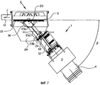
На Фиг.6 и 7 показаны два угловых положения устройства, представленного на Фиг.1 и 2.6 and 7 show two angular positions of the device shown in FIGS. 1 and 2.
На Фиг.8А-D последовательно показаны этапы работы магнитной балки согласно предшествующему уровню техники.On figa-D sequentially shows the steps of the magnetic beam according to the prior art.
На Фиг.9А-Е последовательно показаны этапы работы магнитной балки согласно изобретению.On Figa-E sequentially shown the steps of the magnetic beam according to the invention.
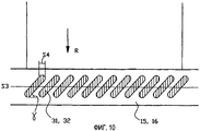
Фиг.10 - вид в плане магнитной балки.10 is a plan view of a magnetic beam.
Устройство 1, представленное на Фиг.1 и 2, расположено таким образом, чтобы подавать полосу R резинового материала, снабженного кордами, предпочтительно стальными, в направлении Х подачи. Устройство 1 подачи подает полосу резинового материала в режущее устройство 2, неподвижно установленное впереди по ходу. Режущее устройство 2 содержит неподвижно установленную раму 9, держатель 5 лезвия, который перемещается вверх и вниз (по направлению Е) и содержит лезвие 5а со скошенной режущей кромкой, и неподвижно установленное противолежащее лезвие, не показанное на чертеже, а также не показанный на чертеже конвейер, расположенный впереди по ходу относительно держателя 5 лезвия и разгружаемый на разгрузочный конвейер 10 в направлении J для разгрузки отрезанных кусков резинового материала, корды в котором расположены под углом к режущим кромкам, известным per se образом.The
Впереди по ходу относительно лезвия 5 режущее устройство 2 снабжено несъемным столом 28, имеющим край 28а с центром S1, причем большая часть края стола имеет круговую форму. В поверхности стола 28 выполнены отверстия (не показанные на чертежах), соединяемые с источником сжатого воздуха для создания воздушной подушки, несущей полотно резинового материала.Upstream of the
Со стороны подачи устройства 1 размещено приспособление 3 для хранения подаваемого обрабатываемого материала, снабженное не показанным подробно на чертеже рулоном резинового материала, подаваемого в устройство 1 и схематично показанного в виде полотна R.On the supply side of the
Приспособление 3 для хранения подаваемого материала связано с устройством 1 подачи таким образом, что их можно перемещать в направлении В как одно целое (см. Фиг.2), посредством шарнирного соединения с режущим устройством 2; данное шарнирное соединение будет обсуждаться далее.The
Устройство 1 подачи содержит нижнюю раму 8 и верхнюю раму 4, которые неподвижно соединены друг с другом соединением, не показанным на чертежах. Нижняя рама 8 жесткая во всех направлениях и является опорой для рольганга 6 (см. также вид в плане на Фиг.2). Рольганг 6 присоединен к круглому, по существу, краю 28а стола 28.The
Верхняя рама 4 жесткая во всех направлениях и снабжена прямыми непрерывными направляющими 7 (прямыми направляющими), на которых подвешен кареточный узел, состоящий из передней каретки 23а и задней каретки 23b, жестко соединенных между собой соединительной тягой 23с. Каретки 23а, 23b также могут быть выполнены как единое целое - данный вариант осуществления представлен на Фиг.3; в этом случае соединительная тяга 23с отсутствует. Каретки 23а, 23b снабжены подвесками 27, с помощью которых каретки 23а, 23b подвешены на прямых направляющих 7 для прямолинейного направленного перемещения по ним в направлении А. Как видно на Фиг.3 и 5, к каретке 23 (или, в случае наличия двух кареток 23(а, b) - к каретке 23b) прикреплена вертикальная планка 24, которая служит для установки серводвигателя 60. Серводвигатель 60 снабжен зубчатым шкивом 60а, приводимым им в движение, по которому движется зубчатый приводной ремень 62, приводящий в действие зубчатый приводной шкив 63, непосредственно вращающий гайку 26, при этом гайка 26 зацепляется со шпинделем 12, который неподвижно прикреплен к верхней раме 4 посредством кронштейнов 25а, 25b.The
Магнитные балки 15 и 16 прикреплены к каретке 23 или к кареткам 23а, 23b. Магнитная балка 16 неподвижно прикреплена к каретке 23, 23b с заднего конца, или сзади по ходу. Магнитная балка 16 продолжается поперек направления А перемещения и снабжена магнитами 32, подвижными относительно магнитной балки 16 в направлении D.
Передняя, или расположенная впереди по ходу, магнитная балка 15 расположена под углом (в горизонтальной плоскости) и прикреплена к каретке 23а или 23. Магнитная балка 15, как дополнительно проиллюстрировано на Фиг.3 и 4(А, В), а также на виде в плане на Фиг.2, прикреплена к раме 30, которая, по существу, изготовлена из одной пластины, например из алюминиевой, и содержит продольную полосу 36, к нижней стороне которой прикреплена магнитная балка 15 - способом крепления, не показанным на чертеже (например, посредством некоторого количества болтов). К нижней стороне полосы 36 прикреплена верхняя полоса 37, также прикрепленная к магнитной балке 15 и придающая планке 30 жесткость. Кроме того, планка 30 содержит полосу 32 с арочным изгибом, к краю которой с целью придания жесткости прикреплена подвешенная полоса 35.The front, or upstream,
Благодаря планке 30, снабженной полосой 32 с арочным изгибом, обеспечивается жесткость магнитной балки 15, особенно в горизонтальной плоскости, с целью поддержания оптимальной прочности балки.Thanks to the
Планка 30 прикреплена к каретке 23а или 23 посредством оси 38 шарнира и шарнирной опоры 39 с возможностью шарнирного перемещения в горизонтальной плоскости вокруг центральной линии S2 в направлении G. Кронштейн 18 с горизонтальной частью 19 свисает с каретки 23а или 23, причем данная горизонтальная часть поддерживает пневмоцилиндр 17, приводимый в действие магистралью 21 сжатого воздуха. Приведенный в действие пневмоцилиндр 17 раздвигает зажимной узел 33. Затем упомянутый зажимной узел 33 с усилием прижимают к нижней стороне полосы 32 с арочным изгибом. С верхней стороны полосы 33 с арочным изгибом к каретке 23 или 23а прикреплена изогнутая соответствующим образом полоса 34 тормозного узла, при этом полоса 34 тормозного узла расположена напротив мест размещения зажимных узлов 33 и соответствующих работающих на сжатом воздухе цилиндров 17, так что зажимные узлы 33 могут прижимать арочную полосу 32 вверх, к полосе 34 тормозного узла. Таким образом, приводя в действие работающие на сжатом воздухе цилиндры 17, можно закреплять положение планки 30 относительно каретки 23, 23а, что касается направления вращения G. Тем самым закрепляется и угловое положение магнитной балки 15. Следует заметить, что, как видно на Фиг.2, 6 и 7, каретка 23а проходит вбок, за направляющую 7, при этом показаны места расположения тормозных узлов 34 и зажимных узлов 33.The
Верхняя рама 4 и нижняя рама 8 прикреплены к режущему устройству 2 с возможностью шарнирного поворота вокруг центральной линии S1 (Фиг.1) в позициях 8а и 61. Прямые направляющие 7 могут продолжаться до самого режущего устройства 2 таким образом, чтобы можно было так разместить магнитную балку 15, чтобы она упиралась в режущее устройство 2. В этом положении центральные линии S1 и S2 предпочтительно совпадают.The
Таким способом мы добиваемся того, чтобы магнитная балка 15 могла придвигать полотно резинового материала как можно ближе к лезвию 5, в результате чего ограничивается риск нежелательных деформаций.In this way, we ensure that the
Благодаря тому, что магнитная балка 15 упирается в режущее устройство 2, режущее устройство 2 оказывается связанным с магнитной балкой 15, и эту связь можно использовать в начале эксплуатации устройства 1 подачи. Перед началом эксплуатации устройства 1 подачи можно сначала привести каретку 23 или каретки 23а, 23b в отведенное «нулевое» положение, известное в данной области техники, а затем с помощью измерений выявить положение, в котором магнитная балка 15 упирается в режущее устройство 2 благодаря перемещению каретки (кареток). Зная эти два положения, можно точно рассчитать величину хода (используя программу для расчетов, установленную в устройстве управления устройства 1 подачи) каретки при подаче, и устройство управления будет управлять серводвигателем 60, используя результаты данных расчетов.Due to the fact that the
В случае необходимости изменения угла α (Фиг.6) между направлением А подачи и направлением J разгрузки каретку 23 перемещают в сторону режущего устройства 2, пока магнитная балка 15 не упрется в режущее устройство 2, например в держатель лезвия 5. Затем пневмоцилиндры 17 разгружают, чтобы прекратить прижим к планке 30. Затем, используя не показанные на чертеже средства, сборочный узел, состоящий из устройства 1 подачи и приспособления 3 для хранения подаваемого материала, поворачивают в направлении В вокруг центральной линии S1, пока не будет получено желаемое угловое положение (например, угол β, показанный на Фиг.7). Затем вновь приводят в действие пневмоцилиндры 17, чтобы зафиксировать новое угловое положение магнитной балки. Данные об этом положении вводят в устройство управления устройства подачи, используя их вышеупомянутым способом для управления серводвигателем 60.If it is necessary to change the angle α (FIG. 6) between the feed direction A and the discharge direction J, the
Наличие непрерывной прямолинейной направляющей 7 для обеих кареток 23а, 23b или каретки 23, а также фиксация углового положения магнитной балки 15, обеспечивают удержание полотна резинового материала (с использованием магнитов) в местах, надежно удерживающих свои взаимные положения во время движения подачи.The presence of a continuous
На примере Фиг.8(А-D) и 9(A-E) можно объяснить еще одну особенность магнитной балки согласно изобретению. В устройстве известного уровня техники, проиллюстрированном на Фиг.8(А-D), магнитная балка 15' снабжена корпусом 40', в котором размещены цилиндры 41', поршневые штоки 42' которых снабжены установленными с нижнего конца магнитами 31'. Резиновый материал, расположенный на столе 28, изображен схематично. На Фиг.8А показано нерабочее положение. Магнитная балка 15' всегда находится на расстоянии Х1 над опорной поверхностью стола 28. После того, как магнитная балка 15 сдвигает резиновый материал 50 (Фиг.8 В), магнит 31' вновь отводят (D). Однако из-за воздействия силы магнитного поля резиновый материал стремится сдвинуться, и образуется выпуклость 51. (Поэтому высота Х1 не должна быть слишком большой. Однако недостаток данного способа состоит в том, что во время возвратного хода может происходить контакт магнитных балок с резиновым материалом). И, наконец, напряжение в резиновом материале преодолевает силу магнитного поля, и материал «отлипает» (см. Фиг.8С), однако на нем остается деформированный участок 52. На Фиг.8D показана отведенная магнитная балка 15', готовая к выполнению следующего хода.On the example of Fig. 8 (A-D) and 9 (A-E), another feature of the magnetic beam according to the invention can be explained. In the prior art device illustrated in FIG. 8 (A-D), the
Магнитная балка 15 согласно изобретению, представленная на Фиг.9(А-Е), снабжена дополнительным средством в виде фиксатора 43, который перемещается вверх и вниз относительно корпуса 40. Как показано на Фиг.9А и 9В, сначала фиксатор 43 перемещается вниз (G), пока не войдет в контакт с поверхностью резинового материала 50. Затем магнит 30 перемещается вниз (Н). Благодаря тому, что фиксатор 43 доходит до резинового материала, предотвращается возникновение выпуклости в резиновом материале 50 при приближении магнита 31.The
По окончании хода транспортирования (Фиг.9С) сначала отводят вверх магнит 31 (D), но фиксатор 43 остается на месте. Затем (Фиг.9D) поднимают вверх, в направлении I, фиксатор 43. В результате резиновый материал остается плоским.At the end of the transport stroke (Fig. 9C), the magnet 31 (D) is first pulled up, but the
Еще одним следствием препятствования приподниманию резинового материала вместе с магнитом является тот факт, что расстояние Х2 от магнита до опорной поверхности стола 28 может быть больше, чем Х1. В результате предотвращается возможное столкновение возвращающейся магнитной балки 15 с резиновым материалом.Another consequence of preventing the lifting of the rubber material with the magnet is the fact that the distance X2 from the magnet to the supporting surface of the table 28 may be greater than X1. As a result, a possible collision of the returning
На Фиг.10 проиллюстрирован еще один, особый, аспект, связанный с магнитной балкой 15. Продольное направление магнитной балки 15 обозначено как «S3». Видно, что магниты 31 имеют продолговатую форму и расположены под углом γ к линии S3. В результате можно сильнее приблизить друг к другу последовательно расположенные магниты в направлении S3. Можно даже создать перекрытие S4. Так достигается оптимальное зацепление резинового материала.Figure 10 illustrates another, particular, aspect associated with the
Claims (39)
Applications Claiming Priority (2)
| Application Number | Priority Date | Filing Date | Title |
|---|---|---|---|
| NL1029863 | 2005-09-02 | ||
| NL1029863A NL1029863C2 (en) | 2005-09-02 | 2005-09-02 | Feeder for cutting device. |
Publications (2)
| Publication Number | Publication Date |
|---|---|
| RU2008112686A RU2008112686A (en) | 2009-10-10 |
| RU2412103C2 true RU2412103C2 (en) | 2011-02-20 |
Family
ID=36228758
Family Applications (1)
| Application Number | Title | Priority Date | Filing Date |
|---|---|---|---|
| RU2008112686A RU2412103C2 (en) | 2005-09-02 | 2006-08-31 | Feeding device for cutter |
Country Status (11)
| Country | Link |
|---|---|
| US (1) | US8549969B2 (en) |
| EP (1) | EP1919811B1 (en) |
| JP (1) | JP5192379B2 (en) |
| KR (1) | KR101305883B1 (en) |
| CN (1) | CN101253115B (en) |
| AT (1) | ATE544710T1 (en) |
| BR (1) | BRPI0615417A2 (en) |
| NL (1) | NL1029863C2 (en) |
| RU (1) | RU2412103C2 (en) |
| TW (1) | TWI367814B (en) |
| WO (1) | WO2007027088A2 (en) |
Families Citing this family (3)
| Publication number | Priority date | Publication date | Assignee | Title |
|---|---|---|---|---|
| DE102012107215B4 (en) * | 2012-08-07 | 2016-12-01 | Karl Eugen Fischer Gmbh | Device for overlapping splicing of cord tape |
| DE102013112742A1 (en) * | 2013-11-19 | 2015-05-21 | Karl Eugen Fischer Gmbh | Cutting device for cutting a thin and sticky tape, in particular a Cordbandes |
| NL2034579B1 (en) * | 2023-04-14 | 2024-10-21 | Vmi Holland Bv | Pick-and-place system, tire manufacturing line and method for picking-up a tire component |
Citations (6)
| Publication number | Priority date | Publication date | Assignee | Title |
|---|---|---|---|---|
| SU1377233A1 (en) * | 1986-03-28 | 1988-02-28 | Украинский Научно-Исследовательский Институт Швейной Промышленности | Arrangement for feeding multilayer plating to blanking press |
| RU1413838C (en) * | 1985-12-09 | 1995-08-27 | Омское научно-производственное предприятие "Прогресс" | Device for production of rubberized cord fabric |
| EP1065043A2 (en) * | 1999-06-28 | 2001-01-03 | The Yokohama Rubber Co., Ltd. | Method and apparatus for producing belt member |
| EP1243404A1 (en) * | 2001-03-20 | 2002-09-25 | Karl Eugen Fischer GmbH Maschinenfabrik | Feeding device, particularly for cord strips |
| EP1329405A2 (en) * | 2002-01-16 | 2003-07-23 | Karl Eugen Fischer GmbH Maschinenfabrik | Shears for cutting web material with adjustable cutting angle |
| EP1286903B1 (en) * | 2000-05-17 | 2004-11-17 | Vmi Epe Holland B.V. | Supply device for supplying rubber material to a cutting device |
Family Cites Families (18)
| Publication number | Priority date | Publication date | Assignee | Title |
|---|---|---|---|---|
| US2767823A (en) * | 1953-01-29 | 1956-10-23 | Beamish Bernard Delacour | Conveyor system |
| DE1255919B (en) | 1961-11-22 | 1967-12-07 | Continental Gummi Werke Ag | Feeding device with a transport path for a rubber path reinforced with wire ropes on a bevel and cross cutting device |
| DE1260131B (en) * | 1964-06-08 | 1968-02-01 | Continental Gummi Werke Ag | Device for feeding a sheet or sheet of rubber to a cutting machine |
| US3616978A (en) * | 1967-07-26 | 1971-11-02 | Stewarts & Lloyds Ltd | Conveyors |
| JPS5146945B1 (en) * | 1969-03-25 | 1976-12-11 | ||
| DE1921749A1 (en) * | 1969-04-29 | 1970-11-12 | Continental Gummi Werke Ag | Inclined or cross cutting device for tracks made of parallel wire ropes |
| JPS529715B2 (en) * | 1971-11-05 | 1977-03-17 | ||
| US4010664A (en) * | 1976-03-19 | 1977-03-08 | The Goodyear Tire & Rubber Company | Bias ply cutter feed apparatus |
| DE2707917A1 (en) * | 1977-02-24 | 1978-08-31 | Fischer Maschf Karl E | Cutting a rubber belt contg. steel wires - used in mfr. of automobile tyres |
| JPS5889294A (en) | 1981-11-20 | 1983-05-27 | アイシン精機株式会社 | Apparatus for stopping rotation of inner hook of horizontal full rotary hook |
| JPS5889294U (en) * | 1981-12-07 | 1983-06-16 | 日東電工株式会社 | Variable angle automatic cutting device |
| JPS6144598A (en) | 1984-08-02 | 1986-03-04 | 三菱重工業株式会社 | Carry-in device for tire cord |
| JPS63230462A (en) | 1987-03-19 | 1988-09-26 | Mitsubishi Heavy Ind Ltd | Tire cord transfer apparatus |
| JP3192838B2 (en) | 1993-09-30 | 2001-07-30 | 三菱重工業株式会社 | Method of changing cutting angle in corded tire material cutting device |
| JP3174683B2 (en) * | 1994-02-02 | 2001-06-11 | 三菱重工業株式会社 | Tire component material loading device for bias cutter |
| JP3207655B2 (en) * | 1994-02-02 | 2001-09-10 | 三菱重工業株式会社 | Bias cutter |
| EP1447210B1 (en) * | 2003-02-13 | 2007-03-07 | Société de Technologie Michelin | Forming and applying a tyre belt ply on a support |
| EP1783072B1 (en) * | 2005-11-04 | 2008-02-13 | Thierry Verroeye | Method and device for handling profile parts, particularly stacking profile parts |
-
2005
- 2005-09-02 NL NL1029863A patent/NL1029863C2/en not_active IP Right Cessation
-
2006
- 2006-08-31 KR KR1020087007982A patent/KR101305883B1/en not_active Expired - Fee Related
- 2006-08-31 US US11/990,590 patent/US8549969B2/en not_active Expired - Fee Related
- 2006-08-31 CN CN2006800319843A patent/CN101253115B/en not_active Expired - Fee Related
- 2006-08-31 EP EP20060783908 patent/EP1919811B1/en not_active Not-in-force
- 2006-08-31 JP JP2008528972A patent/JP5192379B2/en not_active Expired - Fee Related
- 2006-08-31 AT AT06783908T patent/ATE544710T1/en active
- 2006-08-31 BR BRPI0615417-4A patent/BRPI0615417A2/en not_active Application Discontinuation
- 2006-08-31 RU RU2008112686A patent/RU2412103C2/en not_active IP Right Cessation
- 2006-08-31 WO PCT/NL2006/000441 patent/WO2007027088A2/en not_active Ceased
- 2006-09-01 TW TW095132307A patent/TWI367814B/en not_active IP Right Cessation
Patent Citations (6)
| Publication number | Priority date | Publication date | Assignee | Title |
|---|---|---|---|---|
| RU1413838C (en) * | 1985-12-09 | 1995-08-27 | Омское научно-производственное предприятие "Прогресс" | Device for production of rubberized cord fabric |
| SU1377233A1 (en) * | 1986-03-28 | 1988-02-28 | Украинский Научно-Исследовательский Институт Швейной Промышленности | Arrangement for feeding multilayer plating to blanking press |
| EP1065043A2 (en) * | 1999-06-28 | 2001-01-03 | The Yokohama Rubber Co., Ltd. | Method and apparatus for producing belt member |
| EP1286903B1 (en) * | 2000-05-17 | 2004-11-17 | Vmi Epe Holland B.V. | Supply device for supplying rubber material to a cutting device |
| EP1243404A1 (en) * | 2001-03-20 | 2002-09-25 | Karl Eugen Fischer GmbH Maschinenfabrik | Feeding device, particularly for cord strips |
| EP1329405A2 (en) * | 2002-01-16 | 2003-07-23 | Karl Eugen Fischer GmbH Maschinenfabrik | Shears for cutting web material with adjustable cutting angle |
Also Published As
| Publication number | Publication date |
|---|---|
| WO2007027088A3 (en) | 2007-05-24 |
| US8549969B2 (en) | 2013-10-08 |
| TWI367814B (en) | 2012-07-11 |
| ATE544710T1 (en) | 2012-02-15 |
| EP1919811A2 (en) | 2008-05-14 |
| NL1029863C2 (en) | 2007-03-05 |
| TW200716338A (en) | 2007-05-01 |
| KR101305883B1 (en) | 2013-09-06 |
| JP5192379B2 (en) | 2013-05-08 |
| EP1919811B1 (en) | 2012-02-08 |
| BRPI0615417A2 (en) | 2011-05-17 |
| US20100264189A1 (en) | 2010-10-21 |
| KR20080046222A (en) | 2008-05-26 |
| CN101253115B (en) | 2010-08-25 |
| WO2007027088A2 (en) | 2007-03-08 |
| JP2009506899A (en) | 2009-02-19 |
| CN101253115A (en) | 2008-08-27 |
| RU2008112686A (en) | 2009-10-10 |
| WO2007027088A8 (en) | 2008-05-08 |
Similar Documents
| Publication | Publication Date | Title |
|---|---|---|
| CN100398249C (en) | Laser cutting device, laser cutting method and laser cutting system | |
| JP4511823B2 (en) | Tire preparation ply manufacturing apparatus and manufacturing method | |
| CN208529260U (en) | A kind of cutting machine and the transfer device for cutting molding materials | |
| US11279056B2 (en) | Device for carrying out cutting operations on open format edges of a printed product | |
| CN105711123B (en) | Low-angle steel cord cutters splicing auxiliary material conveying device | |
| RU2412103C2 (en) | Feeding device for cutter | |
| US3935056A (en) | Apparatus for splicing parallelogrammatic pieces of rubber cloth without overlap | |
| CN115284387B (en) | A fully automatic large-format gantry platform cutting machine | |
| US4838538A (en) | Sheet material positioning apparatus | |
| CN110370324B (en) | Packaging material cutting device | |
| KR101165333B1 (en) | Cutting machine for molding of automobile | |
| CN110040323B (en) | Full-automatic uninterrupted feeding and discharging linkage type labeling machine | |
| CN214219020U (en) | Single needle machine | |
| JPH07148710A (en) | Double end tenoner | |
| CN117983890B (en) | Automatic change high-speed vertical saw | |
| KR101202056B1 (en) | Attaching Apparatus of the Rubber Strip for Tire | |
| CN117206874A (en) | An automatic feeding riveting press | |
| US6153047A (en) | Page binding method and machine | |
| CN212581116U (en) | Mask sheet-punching machine | |
| JP2008531437A (en) | Apparatus and method for supporting and moving a processing material using a cutting apparatus | |
| CN221021123U (en) | Paper corner protector cutting device | |
| CN117428855B (en) | Rubber sheet equidistant cutting device and its usage method | |
| CN205521548U (en) | Automatic blanking machine of refrigerator temperature controller lead wire sheath | |
| CN218258917U (en) | Product transportation positioning mechanism | |
| CN210551422U (en) | Reciprocating cutter driving mechanism of packaging material cutting device |
Legal Events
| Date | Code | Title | Description |
|---|---|---|---|
| MM4A | The patent is invalid due to non-payment of fees |
Effective date: 20170901 |